Investigations of nanocomposite magnetic materials based on the oxides of iron, nickel, cobalt and silicon dioxide Irina E. Gracheva a , Grazyna Olchowik b , Kamil G. Gareev a , Vyatcheslav A. Moshnikov a , Vladimir V. Kuznetsov a , Jan M. Olchowik c,n a Saint-Petersburg State Electrotechnical University, Microelectronics Department, 5 Professora Popova Street, 197376 Saint-Petersburg, Russia b Medical University of Lublin, Al. Rac!awickie 1, 20-059 Lublin, Poland c Lublin University of Technology, Nadbystrzycka 38, Lublin, Poland article info Article history: Received 28 October 2012 Received in revised form 23 December 2012 Accepted 26 December 2012 Available online 10 January 2013 Keywords: A. Magnetic materials B. Sol-gel growth C. X-ray diffraction D. Magnetic properties abstract This paper is concerned with the study of magnetic nanocomposites containing silicon, iron, nickel, and cobalt oxides. These materials were produced in the form of thin films based on Fe–Si–O, Ni–Co–Si–O and Fe–Ni–Co–Si–O systems and powders based on Fe–Si–O, Ni–Si–O, Co–Si–O and Fe–Ni–Co–Si–O systems using sol–gel technology, through centrifugation, and deposition of ammonia solution. The morphology and magnetic properties of materials in the form of thin films were studied by using the atomic force microscopy. The phase composition, specific surface area and magnetic properties of materials in the form of powders were studied by using the X-ray phase analysis, thermal desorption, vibrational magnetometry and immittance measurements. The dependencies of the main parameters were derived for the magnetic materials from their structure and manufacturing conditions. Ways to optimise the technological processes were proposed, aimed at reducing the size of the magnetic particles in an amorphous lattice. & 2013 Elsevier Ltd. All rights reserved. 1. Introduction Magnetic material nanochemistry is one of the most dynamically developing areas of modern nanotechnology [1–4] and in recent years has absorbed a growing number of researchers from different disciplines: chemistry, physics, biology and medicine [5,6]. It should be emphasised that the magnetic properties of nanomaterials can vary considerably with nano-object size variations. In particular, the magnetisation (per atom) and the magnetic anisotropy of nanopar- ticles can be significantly higher than for macroscopic samples, with the difference in the Curie or Neel temperatures reaching several hundred degrees. Moreover, in magnetic nanomaterials many unu- sual properties become apparent, high magnetoresistance, an unu- sually large magnetocaloric effect [7]. The magnetic properties of nanoparticles depend on many factors, amongst which the following stand out: chemical com- position, type of crystal lattice and its degree of deformation; the size, shape and morphology of the particles; the nature of particle interaction with the surrounding lattice and neighbouring mole- cules. Magnetic nanoparticles are used in information recording and storage systems, in modern permanent magnets, or in magnetic cooling systems [8]. The magnetic metal oxide nano- particles are already used in pharmacology for the treatment of serious diseases, and also in information recording and storage systems, as well as in the creation of highly effective catalysts. The development of modern electronics is also largely associated with the use of the nanoparticle’s magnetic properties, in parti- cular in the so-called. spintronics, in which the nano-objects’ magnetic and electronic interaction properties are utilised [9]. It should be noted, however, that there is a stability problem concerning the magnetic nanodispersion phase due to the instability of such small objects and their tendency to agglomerate. One solution is the creation of composite materials based on an amorphous lattice, such as silica. The introduction of transition metal oxide nanoparticles (including iron) into such a lattice can lead to an increased magnetic moment and coercive force. A convenient, cheap and economical way of producing such materials may be ‘‘sol–gel’’ technology [10–13], which is a kind of combination of developments in nanotechnology and colloidal chemistry [14]. The main aim of this study was to examine the effect of technological regimes of the sol–gel synthesis of thin films as well as powders of Fe–Si–O, Ni–Co–Si–O and Fe–Ni–Co–Si–O systems on morphology, magnetic properties, phase composition, specific surface area and magnetic properties. 2. Experimental The research presented in this paper relates to composites based on such systems as Fe–Si–O, Co–Si–O, Ni–Si–O, Ni–Co–Si–O Contents lists available at SciVerse ScienceDirect journal homepage: www.elsevier.com/locate/jpcs Journal of Physics and Chemistry of Solids 0022-3697/$ - see front matter & 2013 Elsevier Ltd. All rights reserved. http://dx.doi.org/10.1016/j.jpcs.2012.12.021 n Corresponding author. Tel.: þ48 815384701. E-mail address: [email protected] (J.M. Olchowik). Journal of Physics and Chemistry of Solids 74 (2013) 656–663
Transcript
Journal of Physics and Chemistry of Solids 74 (2013) 656–663
Contents lists available at SciVerse ScienceDirect
Journal of Physics and Chemistry of Solids
0022-36
http://d
n Corr
E-m
journal homepage: www.elsevier.com/locate/jpcs
Investigations of nanocomposite magnetic materials based on the oxides ofiron, nickel, cobalt and silicon dioxide
Irina E. Gracheva a, Grazyna Olchowik b, Kamil G. Gareev a, Vyatcheslav A. Moshnikov a,Vladimir V. Kuznetsov a, Jan M. Olchowik c,n
a Saint-Petersburg State Electrotechnical University, Microelectronics Department, 5 Professora Popova Street, 197376 Saint-Petersburg, Russiab Medical University of Lublin, Al. Rac!awickie 1, 20-059 Lublin, Polandc Lublin University of Technology, Nadbystrzycka 38, Lublin, Poland
a r t i c l e i n f o
Article history:
Received 28 October 2012
Received in revised form
23 December 2012
Accepted 26 December 2012Available online 10 January 2013
This paper is concerned with the study of magnetic nanocomposites containing silicon, iron, nickel, and
cobalt oxides. These materials were produced in the form of thin films based on Fe–Si–O, Ni–Co–Si–O
and Fe–Ni–Co–Si–O systems and powders based on Fe–Si–O, Ni–Si–O, Co–Si–O and Fe–Ni–Co–Si–O
systems using sol–gel technology, through centrifugation, and deposition of ammonia solution. The
morphology and magnetic properties of materials in the form of thin films were studied by using the
atomic force microscopy. The phase composition, specific surface area and magnetic properties of
materials in the form of powders were studied by using the X-ray phase analysis, thermal desorption,
vibrational magnetometry and immittance measurements. The dependencies of the main parameters
were derived for the magnetic materials from their structure and manufacturing conditions. Ways to
optimise the technological processes were proposed, aimed at reducing the size of the magnetic
particles in an amorphous lattice.
& 2013 Elsevier Ltd. All rights reserved.
1. Introduction
Magnetic material nanochemistry is one of the most dynamicallydeveloping areas of modern nanotechnology [1–4] and in recentyears has absorbed a growing number of researchers from differentdisciplines: chemistry, physics, biology and medicine [5,6]. It shouldbe emphasised that the magnetic properties of nanomaterials canvary considerably with nano-object size variations. In particular, themagnetisation (per atom) and the magnetic anisotropy of nanopar-ticles can be significantly higher than for macroscopic samples, withthe difference in the Curie or Neel temperatures reaching severalhundred degrees. Moreover, in magnetic nanomaterials many unu-sual properties become apparent, high magnetoresistance, an unu-sually large magnetocaloric effect [7].
The magnetic properties of nanoparticles depend on manyfactors, amongst which the following stand out: chemical com-position, type of crystal lattice and its degree of deformation; thesize, shape and morphology of the particles; the nature of particleinteraction with the surrounding lattice and neighbouring mole-cules. Magnetic nanoparticles are used in information recordingand storage systems, in modern permanent magnets, or inmagnetic cooling systems [8]. The magnetic metal oxide nano-particles are already used in pharmacology for the treatment of
ll rights reserved.
ik).
serious diseases, and also in information recording and storagesystems, as well as in the creation of highly effective catalysts.The development of modern electronics is also largely associatedwith the use of the nanoparticle’s magnetic properties, in parti-cular in the so-called. spintronics, in which the nano-objects’magnetic and electronic interaction properties are utilised [9].
It should be noted, however, that there is a stability problemconcerning the magnetic nanodispersion phase due to the instabilityof such small objects and their tendency to agglomerate. One solutionis the creation of composite materials based on an amorphous lattice,such as silica. The introduction of transition metal oxide nanoparticles(including iron) into such a lattice can lead to an increased magneticmoment and coercive force. A convenient, cheap and economical wayof producing such materials may be ‘‘sol–gel’’ technology [10–13],which is a kind of combination of developments in nanotechnologyand colloidal chemistry [14].
The main aim of this study was to examine the effect oftechnological regimes of the sol–gel synthesis of thin films as wellas powders of Fe–Si–O, Ni–Co–Si–O and Fe–Ni–Co–Si–O systems onmorphology, magnetic properties, phase composition, specific surfacearea and magnetic properties.
2. Experimental
The research presented in this paper relates to compositesbased on such systems as Fe–Si–O, Co–Si–O, Ni–Si–O, Ni–Co–Si–O
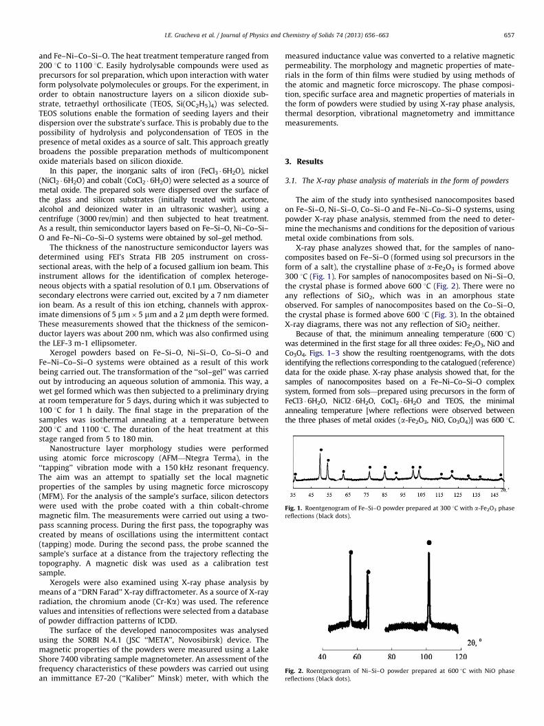
Fig. 1. Roentgenogram of Fe–Si–O powder prepared at 300 1C with a-Fe2O3 phase
reflections (black dots).
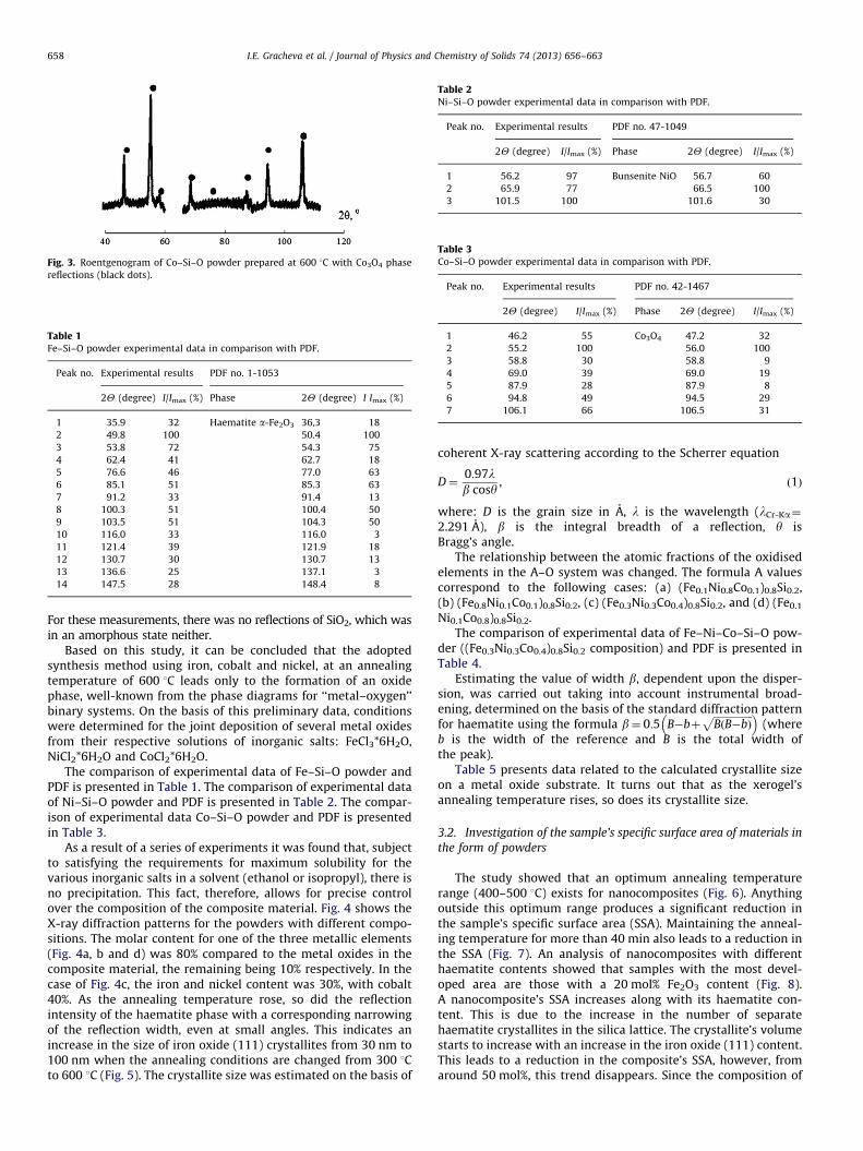
Fig. 2. Roentgenogram of Ni–Si–O powder prepared at 600 1C with NiO phase
reflections (black dots).
I.E. Gracheva et al. / Journal of Physics and Chemistry of Solids 74 (2013) 656–663 657
and Fe–Ni–Co–Si–O. The heat treatment temperature ranged from200 1C to 1100 1C. Easily hydrolysable compounds were used asprecursors for sol preparation, which upon interaction with waterform polysolvate polymolecules or groups. For the experiment, inorder to obtain nanostructure layers on a silicon dioxide sub-strate, tetraethyl orthosilicate (TEOS, Si(OC2H5)4) was selected.TEOS solutions enable the formation of seeding layers and theirdispersion over the substrate’s surface. This is probably due to thepossibility of hydrolysis and polycondensation of TEOS in thepresence of metal oxides as a source of salt. This approach greatlybroadens the possible preparation methods of multicomponentoxide materials based on silicon dioxide.
In this paper, the inorganic salts of iron (FeCl3 �6H2O), nickel(NiCl2 �6H2O) and cobalt (CoCl2 �6H2O) were selected as a source ofmetal oxide. The prepared sols were dispersed over the surface ofthe glass and silicon substrates (initially treated with acetone,alcohol and deionized water in an ultrasonic washer), using acentrifuge (3000 rev/min) and then subjected to heat treatment.As a result, thin semiconductor layers based on Fe–Si–O, Ni–Co–Si–O and Fe–Ni–Co–Si–O systems were obtained by sol–gel method.
The thickness of the nanostructure semiconductor layers wasdetermined using FEI’s Strata FIB 205 instrument on cross-sectional areas, with the help of a focused gallium ion beam. Thisinstrument allows for the identification of complex heteroge-neous objects with a spatial resolution of 0.1 mm. Observations ofsecondary electrons were carried out, excited by a 7 nm diameterion beam. As a result of this ion etching, channels with approx-imate dimensions of 5 mm�5 mm and a 2 mm depth were formed.These measurements showed that the thickness of the semicon-ductor layers was about 200 nm, which was also confirmed usingthe LEF-3 m-1 ellipsometer.
Xerogel powders based on Fe–Si–O, Ni–Si–O, Co–Si–O andFe–Ni–Co–Si–O systems were obtained as a result of this workbeing carried out. The transformation of the ‘‘sol–gel’’ was carriedout by introducing an aqueous solution of ammonia. This way, awet gel formed which was then subjected to a preliminary dryingat room temperature for 5 days, during which it was subjected to100 1C for 1 h daily. The final stage in the preparation of thesamples was isothermal annealing at a temperature between200 1C and 1100 1C. The duration of the heat treatment at thisstage ranged from 5 to 180 min.
Nanostructure layer morphology studies were performedusing atomic force microscopy (AFM—Ntegra Terma), in the‘‘tapping’’ vibration mode with a 150 kHz resonant frequency.The aim was an attempt to spatially set the local magneticproperties of the samples by using magnetic force microscopy(MFM). For the analysis of the sample’s surface, silicon detectorswere used with the probe coated with a thin cobalt-chromemagnetic film. The measurements were carried out using a two-pass scanning process. During the first pass, the topography wascreated by means of oscillations using the intermittent contact(tapping) mode. During the second pass, the probe scanned thesample’s surface at a distance from the trajectory reflecting thetopography. A magnetic disk was used as a calibration testsample.
Xerogels were also examined using X-ray phase analysis bymeans of a ‘‘DRN Farad’’ X-ray diffractometer. As a source of X-rayradiation, the chromium anode (Cr-Ka) was used. The referencevalues and intensities of reflections were selected from a databaseof powder diffraction patterns of ICDD.
The surface of the developed nanocomposites was analysedusing the SORBI N.4.1 (JSC ‘‘META’’, Novosibirsk) device. Themagnetic properties of the powders were measured using a LakeShore 7400 vibrating sample magnetometer. An assessment of thefrequency characteristics of these powders was carried out usingan immittance E7-20 (‘‘Kaliber’’ Minsk) meter, with which the
measured inductance value was converted to a relative magneticpermeability. The morphology and magnetic properties of mate-rials in the form of thin films were studied by using methods ofthe atomic and magnetic force microscopy. The phase composi-tion, specific surface area and magnetic properties of materials inthe form of powders were studied by using X-ray phase analysis,thermal desorption, vibrational magnetometry and immittancemeasurements.
3. Results
3.1. The X-ray phase analysis of materials in the form of powders
The aim of the study into synthesised nanocomposites basedon Fe–Si–O, Ni–Si–O, Co–Si–O and Fe–Ni–Co–Si–O systems, usingpowder X-ray phase analysis, stemmed from the need to deter-mine the mechanisms and conditions for the deposition of variousmetal oxide combinations from sols.
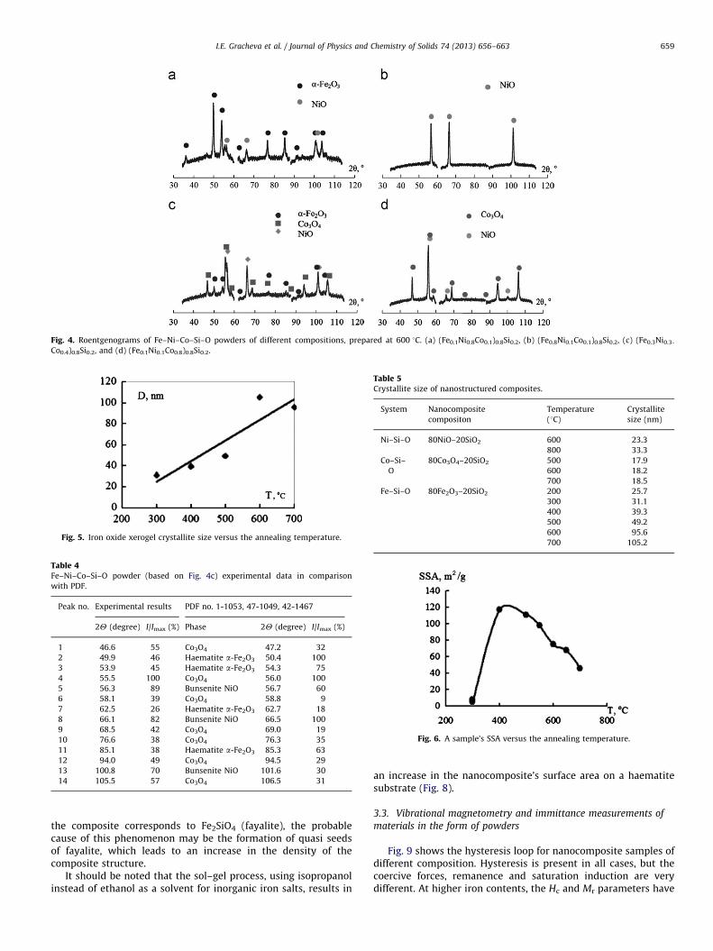
X-ray phase analyzes showed that, for the samples of nano-composites based on Fe–Si–O (formed using sol precursors in theform of a salt), the crystalline phase of a-Fe2O3 is formed above300 1C (Fig. 1). For samples of nanocomposites based on Ni–Si–O,the crystal phase is formed above 600 1C (Fig. 2). There were noany reflections of SiO2, which was in an amorphous stateobserved. For samples of nanocomposites based on the Co–Si–O,the crystal phase is formed above 600 1C (Fig. 3). In the obtainedX-ray diagrams, there was not any reflection of SiO2 neither.
Because of that, the minimum annealing temperature (600 1C)was determined in the first stage for all three oxides: Fe2O3, NiO andCo3O4. Figs. 1–3 show the resulting roentgenograms, with the dotsidentifying the reflections corresponding to the catalogued (reference)data for the oxide phase. X-ray phase analysis showed that, for thesamples of nanocomposites based on a Fe–Ni–Co–Si–O complexsystem, formed from sols—prepared using precursors in the form ofFeCl3 �6H2O, NiCl2 �6H2O, CoCl2 �6H2O and TEOS, the minimalannealing temperature [where reflections were observed betweenthe three phases of metal oxides (a-Fe2O3, NiO, Co3O4)] was 600 1C.
Fig. 3. Roentgenogram of Co–Si–O powder prepared at 600 1C with Co3O4 phase
reflections (black dots).
Table 1Fe–Si–O powder experimental data in comparison with PDF.
Peak no. Experimental results PDF no. 1-1053
2Y (degree) I/Imax (%) Phase 2Y (degree) I Imax (%)
1 35.9 32 Haematite a-Fe2O3 36,3 18
2 49.8 100 50.4 100
3 53.8 72 54.3 75
4 62.4 41 62.7 18
5 76.6 46 77.0 63
6 85.1 51 85.3 63
7 91.2 33 91.4 13
8 100.3 51 100.4 50
9 103.5 51 104.3 50
10 116.0 33 116.0 3
11 121.4 39 121.9 18
12 130.7 30 130.7 13
13 136.6 25 137.1 3
14 147.5 28 148.4 8
Table 2Ni–Si–O powder experimental data in comparison with PDF.
I.E. Gracheva et al. / Journal of Physics and Chemistry of Solids 74 (2013) 656–663658
For these measurements, there was no reflections of SiO2, which wasin an amorphous state neither.
Based on this study, it can be concluded that the adoptedsynthesis method using iron, cobalt and nickel, at an annealingtemperature of 600 1C leads only to the formation of an oxidephase, well-known from the phase diagrams for ‘‘metal–oxygen’’binary systems. On the basis of this preliminary data, conditionswere determined for the joint deposition of several metal oxidesfrom their respective solutions of inorganic salts: FeCl3*6H2O,NiCl2*6H2O and CoCl2*6H2O.
The comparison of experimental data of Fe–Si–O powder andPDF is presented in Table 1. The comparison of experimental dataof Ni–Si–O powder and PDF is presented in Table 2. The compar-ison of experimental data Co–Si–O powder and PDF is presentedin Table 3.
As a result of a series of experiments it was found that, subjectto satisfying the requirements for maximum solubility for thevarious inorganic salts in a solvent (ethanol or isopropyl), there isno precipitation. This fact, therefore, allows for precise controlover the composition of the composite material. Fig. 4 shows theX-ray diffraction patterns for the powders with different compo-sitions. The molar content for one of the three metallic elements(Fig. 4a, b and d) was 80% compared to the metal oxides in thecomposite material, the remaining being 10% respectively. In thecase of Fig. 4c, the iron and nickel content was 30%, with cobalt40%. As the annealing temperature rose, so did the reflectionintensity of the haematite phase with a corresponding narrowingof the reflection width, even at small angles. This indicates anincrease in the size of iron oxide (111) crystallites from 30 nm to100 nm when the annealing conditions are changed from 300 1Cto 600 1C (Fig. 5). The crystallite size was estimated on the basis of
coherent X-ray scattering according to the Scherrer equation
D¼0:97lb cosy
, ð1Þ
where: D is the grain size in A, l is the wavelength (lCr-Ka¼
2.291 A), b is the integral breadth of a reflection, y isBragg’s angle.
The relationship between the atomic fractions of the oxidisedelements in the A–O system was changed. The formula A valuescorrespond to the following cases: (a) (Fe0.1Ni0.8Co0.1)0.8Si0.2,(b) (Fe0.8Ni0.1Co0.1)0.8Si0.2, (c) (Fe0.3Ni0.3Co0.4)0.8Si0.2, and (d) (Fe0.1
Ni0.1Co0.8)0.8Si0.2.The comparison of experimental data of Fe–Ni–Co–Si–O pow-
der ((Fe0.3Ni0.3Co0.4)0.8Si0.2 composition) and PDF is presented inTable 4.
Estimating the value of width b, dependent upon the disper-sion, was carried out taking into account instrumental broad-ening, determined on the basis of the standard diffraction patternfor haematite using the formula b¼ 0:5 B�bþ
b is the width of the reference and B is the total width ofthe peak).
Table 5 presents data related to the calculated crystallite sizeon a metal oxide substrate. It turns out that as the xerogel’sannealing temperature rises, so does its crystallite size.
3.2. Investigation of the sample’s specific surface area of materials in
the form of powders
The study showed that an optimum annealing temperaturerange (400–500 1C) exists for nanocomposites (Fig. 6). Anythingoutside this optimum range produces a significant reduction inthe sample’s specific surface area (SSA). Maintaining the anneal-ing temperature for more than 40 min also leads to a reduction inthe SSA (Fig. 7). An analysis of nanocomposites with differenthaematite contents showed that samples with the most devel-oped area are those with a 20 mol% Fe2O3 content (Fig. 8).A nanocomposite’s SSA increases along with its haematite con-tent. This is due to the increase in the number of separatehaematite crystallites in the silica lattice. The crystallite’s volumestarts to increase with an increase in the iron oxide (111) content.This leads to a reduction in the composite’s SSA, however, fromaround 50 mol%, this trend disappears. Since the composition of
Fig. 4. Roentgenograms of Fe–Ni–Co–Si–O powders of different compositions, prepared at 600 1C. (a) (Fe0.1Ni0.8Co0.1)0.8Si0.2, (b) (Fe0.8Ni0.1Co0.1)0.8Si0.2, (c) (Fe0.3Ni0.3-
Co0.4)0.8Si0.2, and (d) (Fe0.1Ni0.1Co0.8)0.8Si0.2.
Fig. 5. Iron oxide xerogel crystallite size versus the annealing temperature.
Table 4Fe–Ni–Co–Si–O powder (based on Fig. 4c) experimental data in comparison
with PDF.
Peak no. Experimental results PDF no. 1-1053, 47-1049, 42-1467
Table 5Crystallite size of nanostructured composites.
System Nanocomposite
compositon
Temperature
(1C)
Crystallite
size (nm)
Ni–Si–O 80NiO–20SiO2 600 23.3
800 33.3
Co–Si–
O
80Co3O4–20SiO2 500 17.9
600 18.2
700 18.5
Fe–Si–O 80Fe2O3–20SiO2 200 25.7
300 31.1
400 39.3
500 49.2
600 95.6
700 105.2
Fig. 6. A sample’s SSA versus the annealing temperature.
I.E. Gracheva et al. / Journal of Physics and Chemistry of Solids 74 (2013) 656–663 659
the composite corresponds to Fe2SiO4 (fayalite), the probablecause of this phenomenon may be the formation of quasi seedsof fayalite, which leads to an increase in the density of thecomposite structure.
It should be noted that the sol–gel process, using isopropanolinstead of ethanol as a solvent for inorganic iron salts, results in
an increase in the nanocomposite’s surface area on a haematitesubstrate (Fig. 8).
3.3. Vibrational magnetometry and immittance measurements of
materials in the form of powders
Fig. 9 shows the hysteresis loop for nanocomposite samples ofdifferent composition. Hysteresis is present in all cases, but thecoercive forces, remanence and saturation induction are verydifferent. At higher iron contents, the Hc and Mr parameters have
Fig. 7. Fe–Si–O sample’s SSA versus the duration of the heat treatment.
Fig. 8. Fe–Si–O sample’s SSA versus the percentage of haematite in the
nanocomposite.
Fig. 9. Hysteresis loops for samples with different oxidiser A composition.
Table 6The samples’ basic magnetic properties.
Sample (average content of A’s
oxidisable components)
Hc (Oe) Ms (emu/g) Mr (emu/g)
Fe0.66Co0.17Ni0.17 67.38 8.45 3.7
Fe0.5Co0.25Ni0.25 65.27 5.29 1.6
Fe0.25Co0.5Ni0.25 19.31 5.87 2.3
Fe0.33Co0.33Ni0.33 64.37 8.02 1.0
Fe0.2Co0.6Ni0.2 19.56 5.62 0.7
Fig. 10. The frequency of dependency of effective relative permeability for
samples with different averaged oxidant A values.
I.E. Gracheva et al. / Journal of Physics and Chemistry of Solids 74 (2013) 656–663660
high values, while composites with a predominance of cobaltcompounds are characterised by a low value for the coercive forcewith the possibility of changes in saturation induction. Table 6was created based on the data for the shape of the hysteresis loop,and which contains the main values characterising the magneticproperties for the samples.
Fig. 10 shows the frequency dependency of the relativemagnetic permeability for samples of different compositions,with an averaged oxidisability, for A. The material with an A
composition of Fe0.5Co0.25Ni0.25 displaying the best properties atlow field intensities and having a small hysteresis loop was thebest choice, when considering frequencies up to 1 MHz. However,both materials with an A composition predominantly cobalt werecharacterised by a higher magnetic permeability dispersion fre-quency dependency compared with samples having an ironcontent.
3.4. The atomic force microscopy of materials in the
form of thin films
The conducted experiments showed that during ‘‘sol–gel’’processes, when the fractal dimensions of the iron oxide nano-particles reach a critical size (probably corresponding to thesingle-domain states), there is an evolution of fractal aggregatesinto a collective form. These also converge and clusters of radiallysymmetrical ‘‘dumbbells’’ form (Fig. 11).
Figs. 12 and 13 illustrate the possibility of creating complexnanocomposite systems in ‘‘sol–gel’’ processes under conditionsof hierarchical self-organisation. It turns out that dendrite-typeinclusions can occur in the layer structures of systems (Fig. 14).
An AFM picture of a nanocomposite film shown in Fig. 15shows a Bitter–Akulov pattern in the shape of a ‘‘fir’’.
3.5. Magnetic force microscopy of materials in the form of thin films
Modern scanning microscopy is a set of methods that provideimaging of the surface in different analytical responses. Atdistances comparable to nanometers, the dominant forces arevan der Waals forces or other strength of intermolecular interac-tions. But if the tip to charge or use the magnetic tip, and thendismissed from the sample surface at a distance greater than thevan der Waals forces, will remain long-distance interaction. Onthis principle, the scanning magnetic forces microscopy method isbased, which was used in this work.
As mentioned earlier, this study attempted to locally set themagnetic properties of samples using the MFM. The experimentwas performed using a two pass method. In the first pass, thetopography was shaped (Fig. 16a), whilst during the second pass,at a distance from the relief’s surface, the spatial distribution ofthe magnetic field along the z-axis was measured on the surfaceof the nanocomposites, grown on silicon dioxide and iron oxidesubstrates. An image of this scan is shown in Fig. 16b. Based onthe results obtained it seems probable that the spherical shapes inthe form of irregular ‘‘dumbbells’’ can characterise domain areasresulting from considerable differences in the phase of thecantilever oscillations between the image and the surfacetopography.
Fig. 11. AFM images of Fe–Si–O system nanocomposite films, T¼6001C, illustrating the ‘‘dumbbell’’ clusters. Image dimensions: (a) 20 mm�20 mm, (b) 6 mm�6 mm.
Fig. 12. An AFM image of the Ni–Co–Si–O system nanocomposite film (scan area:
30 mm�30 mm).
Fig. 13. An AFM image of the Fe–Ni–Co–Si–O system nanocomposite film (scan
area: 10 mm�10 mm).
Fig. 14. An AFM image of the Fe–Ni–Co–Si–O system nanocomposite film (scan
area: 30 mm�30 mm).
Fig. 15. An AFM image of the Fe–Ni–Co–Si–O system nanocomposite film (scan
area: 50 mm�50 mm).
I.E. Gracheva et al. / Journal of Physics and Chemistry of Solids 74 (2013) 656–663 661
4. Discussions
The studies show that the phase behaviour of the variousmetal oxides can vary, despite the same molar fraction content.
For structures with a predominance of iron (Fig. 4b), in addition tothe haematite reflections, the presence of a nickel oxide phase isseen. However, there are no cobalt oxide reflections. As might be
Fig. 16. An image of (a) the topography and (b) the spatial distribution of the magnetic field along the z-axis, on the surface of nanocomposites, grown on silicon dioxide
and iron oxide substrates (scan area: 70 mm�70 mm).
I.E. Gracheva et al. / Journal of Physics and Chemistry of Solids 74 (2013) 656–663662
expected, with a high nickel content (Fig. 4a), relatively lessintense iron and cobalt reflections are not observed. However,this fact may result from at least two causes: (a) the dissolution ofa substantial part of iron and cobalt in the amorphous silicalattice; (b) the creation of an alloy based on a NiO cubic structurein which the iron and cobalt act as dopants, without significantlychanging the structure (during X-ray studies). Fig. 4d can be usedfor the logical explanation of these assumptions, thus confirmingthis crystallisation property of nickel oxide. An interesting fact isthat, despite having the lowest formation temperature (secondaryreflections were not observed at 200 1C) in a multicompositionsystem, haematite produces the least ordered reflections in thecrystal phase.
For the case shown in Fig. 4c, the metallic content of thecomponents is similar. In this situation, reflections are observedfrom all three oxides. The most intense peaks correspond to theoxides of nickel, while the haematite crystallites only produce low-intensity reflections. The substance produced in a permanentmagnetic field exhibited ferrimagnetic properties, whereas simi-larly synthesised simple Fe (111), Ni and Co oxides did not exhibitany reaction in a magnetic field, or in the case of a-Fe2O3 just avery weak interaction. X-ray phase analysis did not reveal theformation of binary oxides (spinel ferrites) under these synthesisconditions, but on the basis of the phase diagrams for NiO–Fe2O3
and Co3O4–Fe2O3, presented in [15], the magnetic properties of thematerials under investigation result from the presence of aninsignificant amount of a ferrimagnetic phase in the form of binaryoxides, and a crucial part of the composite is a mixture of a-Fe2O3,NiO and Co3O4. This provides a basis to conclude that it is mainly achange in the relationship of these components, with the varia-bility in the composition of the starting metal salt solutions, whichdetermines the final properties of the substance (m(f), Mr, Ms, Hc).
In addition to the basic physical components of the compositemagnetic material, influencing the inertia to the magnetisingprocesses, including different electrical conductivities for theoxides, the particle size plays an important role. Along with areduction in the size of the nanocrystallites, there may be atransition to single-domain grains, in conjunction with theappearance of a superparamagnetic state during a subsequentsize reduction. It is known that the volume of magnetic materialis divided into domains in its pursuit of the minimum total energystate. Between the domains there are transition regions—thedomain walls. The domain wall energy as a proportion of thetotal energy increases rapidly as the linear dimensions decrease.The critical nanocluster size, below which it is energetically
unfavourable for domains to exist, was calculated for the firsttime by Kondorskyi in 1952 [16]. This value was approximately10 nm for conventional ferromagnetic materials such as Fe, Ni,and Co. Creating a domain wall requires additional energy, whichvaries between 0.01 and 1�10�7 J/cm2 for different materials
The English physicists Stoner and Wohlfarth [17] proposed asimple model for magnetising single-domain nanoparticles. Accord-ing to this model, during the demagnetisation of the nanoparticles, atall times all the forces rotate, so that they are aligned parallel to eachother. Of course, the Stoner–Wohlfarth model is an approximation,but the important thing is that it allows for the understanding of thesuperparamagnetism effect. If the particle size becomes small, thebarrier height between the energy minima can be comparable to thethermal energy. In other words, magnetic nanocomposites consistingof nanoclusters, under favourable superparamagnetism conditions,will not possess a magnetic moment in the absence of an externalmagnetic field. However, they exhibit strong magnetic propertieswhen placed in an external magnetic field.
The main difference in the shape and location of the m(f) curve(for example, for two different cases shown in Fig. 10) confirmsthe fact that at this stage the conditions for the ‘‘sol–gel’’synthesis of magnetic nanocomposites with properties deter-mined by size have been determined. The composites obtainedat low temperatures have a much better frequency stability. Itwould be very beneficial to conduct further investigations inorder to obtain ferrite phase nanocomposites at much lowertemperatures than permitted by current conventional methods.
It is known that the presence of triangular regions near the surfaceof a magnetic material, where the directions of magnetisation normalto the axis of easy magnetisation, increases the magnetic anisotropicenergy. This not only leads to a closed magnetic circuit, but it alsocauses a reduction in magnetostatic energy and corresponds to theminimum total energy. The formation of wedge-shaped regionsbecomes energetically favourable. If the surface of the magneticmaterial is slightly inclined to the plane containing the axis of easymagnetisation, regions of Bitter–Akulov patterns in the shape of a‘‘fir’’ are created. Morphology studies of the layers, which contain afunctional element of the single and double metal oxides from theiron subgroup, including nickel and manganese ferrites, as well asrare earth oxides, have shown the formation of symmetric particleswith a porous structure, similar to those shown in Fig. 11. This mayindicate the presence of a magnetic field, conditioned by the presenceof metal cations with an unpaired spin in the sol, which during thecreation of a crystal lattice arrange themselves in accordance with theprinciple of minimum energy.
I.E. Gracheva et al. / Journal of Physics and Chemistry of Solids 74 (2013) 656–663 663
5. Conclusions
The X-ray phase analysis of xerogel powders based on Fe–Si–Oshowed that after heat treatment above 400 1C, a haematite(a-Fe2O3) nanophase with a rhombohedral structure was created(R-3c space group) in the absence of any reflections associatedwith the amorphous state of SiO2. X-ray phase analysis of thexerogel powders, based on Co–Si–O showed that after heattreatment above 500 1C, a cobalt oxide Co3O4 phase with ahexagonal symmetry is created (Fd-3m space group). It is anundisputed fact that for Ni–Si–O, the minimum annealing tem-perature is 600 1C, when the NiO phase reflections show up on theroentgenogram having a rhombohedral symmetry (R-3m spacegroup).
The studies carried out in this paper have shown that as theannealing temperature of the binary xerogel powders rises, so toodoes the metal oxide crystallite size. It was established that theminimum annealing temperature of the complex xerogel powders(Fe–Ni–Co–Si–O system) is 600 1C.
Studies have shown that for the case of an equal molar contentof oxidising components in the initial solution, the relative ratioof the diffraction peaks’ intensities may vary considerably, theminimum for iron oxide, while the maximum for nickel oxide.It was also found that under certain conditions of synthesising‘‘sol–gel’’, when the fractal dimensions of the iron oxide nano-particles reach a critical value, fractal aggregates evolve intocollections, which converge forming radially symmetrical ‘‘dumb-bell’’ shaped nanoparticle clusters. The analysis showed thepossibility of obtaining magnetic layers of nanocomposites basedon Fe–Ni–Co–Si–O system, whose structure contains spheroidaland dendrite-type inclusions and Bitter–Akulov patterns in theshape of a ‘‘fir’’. Studies have shown the possibility to createnanostructured materials based on metal oxides from the ironsubgroup through hierarchical self-organisation.
In these studies, related to attempts to locally set the magneticproperties of samples using an atomic force microscope, it wasfound that the observed irregular ‘‘dumbbell’’ shaped structurescould be due to the existence of domain regions. The study ofxerogel powders based on iron oxide and silica nanocomposites,using X-ray phase analysis, helped to determine the optimalconditions for ‘‘sol–gel’’ synthesis, necessary for obtaining themost developed area of the xerogel powder containing the
haematite nanophase. It was observed that the maximum areacan be achieved when the composition of the 20SiO2–80Fe2O3
(mol%) nanocomposite is subjected to heat treatment at tempera-tures ranging from 400 1C to 500 1C. It was also found that at ahigh iron content in nanocomposites containing iron oxide, cobaltand nickel, the Mr and Hc parameters take on large values whilethe nanocomposites with a predominance of cobalt compoundsare characterised by low values of the coercive force.
References
[1] S.P. Gubin (Ed.), Magnetic Nanoparticles, Wiley-VCH Verlag GmbH, 2009.[2] P.N. Parera, A. Kouki, J. Finne, R.J. Pieters, Detection of pathogenic Strepto-
coccus suis bacteria using magnetic glycoparticles, Org. Biomol. Chem.8 (2010) 2425.
[3] A.G. Roca, et al., Progress in the preparation of magnetic nanoparticles forapplications in biomedicine, J. Phys. D.: Appl. Phys. 42 (2009) 224002.
[4] P. Tartaj, et al., The preparation of magnetic nanoparticles for applications inbiomedicine, J. Phys. D.: Appl. Phys. 36 (2003) R182.
[5] N. Perez, et al., Nanostructural origin of the spin and orbital contribution tothe magnetic moment in Fe3�xO4 magnetite nanoparticles, Appl. Phys. Lett.94 (2009) 093108.
[6] K.M. Krishnan, Biomedical nanomagnetics: a spin through possibilities inimaging, diagnostics, and therapy, IEEE Trans. Magn. 46 (7) (2010) 2523.
[7] G. Srajer, et al., Advances in nanomagnetism via X-ray, J. Mag. Mag. Mater.307 (2006) 1.
[9] A. Bernand- Mantel, P. Seneor, N. Lidgi, Evidance for spin injection in a singlemetallic nanoparticle: a step towards nanospintronics, Appl. Phys. Lett.89 (2006) 062502.
[10] V.A. Moshnikov, et al., Hierarchical nanostructured semiconductor porousmaterials for gas sensors, J. Non-Crystal. Solids 356 (2010) 2020.
[11] I.E. Gracheva, V.A. Moshnikov, S.S. Karpova, E.V. Maraeva, Net-like structuredmaterials for gas sensors, J. Phys.: Conf. Ser., 291 (2011) 012017.
[12] I.E. Gracheva, et al., Nanostructured materials obtained under conditions ofhierarchical self-assembly and modified by derivative forms of fullerenes,J. Non-Crystal. Solids 358 (2012) 433.
[13] V.A. Moshnikov, I.E. Gracheva, M.G. An’chkov, Investigation of sol–gel derivednanomaterials with a hierarchical structure, Glass Phys. Chem. 37 (5) (2011)485.
[14] C.J. Brinker, G.W. Scherer, Sol–Gel Science. The Physics and Chemistry ofSol–Gel Processing, Academic Press, San Diego, 1990.
[15] N.P. Lyakisheva (Ed.), Handbook of Phase Diagrams of Binary Metal Systems,vol. 3, Mashinostroenie, Moscow, 2000 (in Russian).
[16] E.I. Kondorskyi, One-dimensional particle theory papers of Academy ofSciences of the Soviet Union, Phys. Ser. 82 (1952) 365, in Russian.
[17] E.C. Stoner, E.P. Wohlfarth, Mechanism of magnetic hysteresis in hetero-geneous alloys, Phil. Trans. R. Soc. Lond. 240 (826) (1948) 599.


![Nanocomposite [5]](https://static.documents.pub/doc/80x56/577c7ecf1a28abe054a26499/nanocomposite-5.jpg)


