Received: September 2013, Accepted: November 2013Przemyslaw Moczko Faculty of Mechanical Engineering, Wroclaw University of Technology Lukasiewicza 7/9, 50-371 Wroclaw, Poland E-mail: [email protected]
Eugeniusz Rusinski Professor
Wroclaw University of Technology Faculty of Mechanical Engineering, Poland
Przemyslaw Moczko Assistant Professor
Wroclaw University of Technology Faculty of Mechanical Engineering, Poland
Piotr Odyjas MSc
Wroclaw University of Technology Faculty of Mechanical Engineering, Poland
Damian Pietrusiak Assistant Professor
Wroclaw University of Technology Faculty of Mechanical Engineering, Poland
Investigations of Structural Vibrations Problems of High Performance Machines High performance machines are prone to presence of different types of dynamic loads, which can lead to vibrations of the entire structures or their local parts. In the paper examples of identifications of vibration problems of High Performance Machines are shown. Investigations base on experimental methods and numerical simulations. In addition, the methods of preventing vibration of the investigated objects such as bucket wheel excavators, roller mills, crushers, load carrying structures are presented. Keywords: structural vibrations, experimental methods, numerical simulations.
1. INTRODUCTION
The High Performance Machines are prone to many different dynamic effects, which can lead to vibrations of the entire structures or their local parts. There are various reasons of such problems. One of the root causes is that in designing practice effects concerned with the running dynamic of designed objects are often omitted or insufficiently into consideration. The other is that dynamic effects are still difficult to recognise and thus consider at the designing stage. This state causes the occurrence of unexpected problems during the operation of the High Performance machines [1-3]. This is also confirmed in the designing rules and standards, where no special requirements are given, or they are mentioned as additional load, which is considered as constant factor [4-6]. More advanced requirements related to resonance vibrations reasons and effects are given as a designing rule rarely. Results of such poor designing works can be present then in the operation [7-9]. Excessive vibrations, cracks, deformations, wear, mechanical failures are typical indicators of such problems. It is very important to provide proper and quick correcting actions to prevent costly failures or catastrophic breakdowns. The first step is to identify reasons of problems. This is usually done with the use of on-site tests and advanced calculations based on theories of vibrations or numerical analyses [FEM, CFD etc.]. The numerical analyses are frequently used for such purposes due to a wide range of applications available in various systems such as nonlinear or linear static or dynamic, dynamic response and frequency analyses and many more [10, 11].
When the problem is properly identified it is the next step to provide correct actions to bring object to normal and safe operational mode. What is obvious there are no universal solutions for all identified issues. Experience says that each case has to be investigated separately due
to many differences related to reasons of excessive vibrations, effects and possible ways of solutions. At this stage of investigations numerical analyses are commonly used [12-15]. When the problem is identified it is possible to use numerical simulations of the object to incorporate modifications and calculate what the effects of changes are. The advantage of such approach is that there is a numerical model of existing problematic object, which is verified by on-site measurements and with such a tool it is possible to perform various modifications and choose the best solution to eliminate problems in operation.
In the following sections a few examples of identifications of vibration problems of High Performance Machines are shown. Investigations base on experimental methods [16] and numerical simulations. In addition, the methods of preventing vibration of the investigated objects such as bucket wheel excavators, roller mills, crushers load carrying structures are presented as well [17].
2. EXAMPLES OF IDENTIFICATION AND
PREVENTION OF STRUCTURAL VIBRATIONS
Examples of identification and corrective actions of new or existing machines are presented in the following subsections. As already mentioned each of the case is considered as individual problem and approaches related to investigations and solutions are different.
2.1 Prevention of resonance vibrations of bucket
wheel excavator
The first example is to show that advanced analyses can be used at the designing stage to prevent possible resonance vibrations. Despite the standard requirements [DIN 22261] don’t require advanced dynamic analyses, the new designed bucket wheel excavator KWK 1500 has been checked for its modal characteristics. Surface mining machinery belongs to the group of heavy duty machines that are strongly exposed to the dynamic loads. Acting load derives from excavating system and its periodicity is directly related with the system characteristic.
306 ▪ VOL. 41, No 4, 2013 FME Transactions
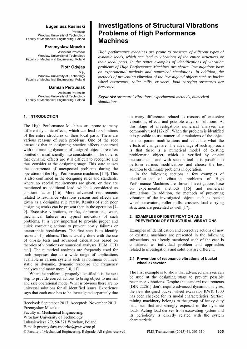
In purpose of dynamic characteristics identification, complete finite element model of the slew able superstructure was built in the CAE system (Figure 1.).
Figure 1: The numerical model Slew-able superstructure of the KWK 1500 excavator
Structural members were substituted by the beam and shell elements. Detailed representation of the superstructure was required for popper simulations. The subassemblies of the lower part like undercarriage were replaced by the deformable elastic elements of corresponding stiffness. Simulations of the structure were performed to establish global and local natural frequencies. The calculated data were analysed then in consideration of excitation frequency which is related to design of excavating unit (bucket wheel and the drive).
The preformed simulations pointed out that the second harmonic of the excitation frequency is close the range of the 6th structural mode of the excavator and equals 2.03Hz. The deflection shape (Figure 2) creates large horizontal displacement of counterweight boom and vertical dis-placement of its supporting structure.
Figure 2: The 6th normal mode of the excavator
The deflection shape is directly related to the support of the counterweight boom of the machine. The front mounting point of the boom is flexible and creates possibility of large dis-placement. The analysed system of the counterweight support is shown in Figure 3.
Figure 3: The sketch of the supporting system of the counterweight support in preliminary version
In such design the excavator will operate with increased vibration amplitudes of the counterweight boom. With high probability, this will lead to fatigue
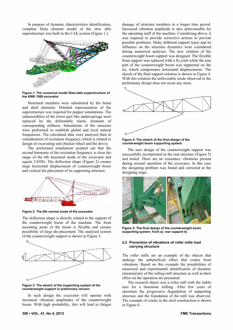
damage of structure members in a longer time period. Increased vibration amplitude is also unfavourable for the operating staff of the machine. Considering above, it was required to provide corrective actions to prevent possible problems. Many different support types and its influence on the structure dynamics were considered during numerical analyses. The new solution of the counterweight boom support was designed. The flexible front support was replaced with a fix joint while the rear part of the counterweight boom was supported on the tie, which compensates horizontal displacements. The sketch of the final support solution is shown in Figure 4. With this solution the unfavorable mode observed in the preliminary design does not occur any more.
Figure 4: The sketch of the final design of the counterweight boom supporting system
The new design of the counterweight support was successfully incorporated in the real structure (Figure 5) and tested. There are no resonance vibrations present during normal operation of the excavator. In this case the designing problem was found and corrected at the designing stage.
Figure 5: The final design of the counterweight boom supporting system: front a); rear support b)
2.2 Prevention of vibrations of roller mills load
carrying structure
The roller mills are an example of the objects that undergo the unbeneficial effect that comes from vibrations. Based on this example the possibilities of numerical and experimental identification of dynamic characteristic of the rolling mill structure as well as their effect on the operation are presented.
The research object was a roller mill with the stable race for a limestone milling. After few years of operation the progressive degradation of supporting structure and the foundation of the mill was observed. The example of cracks in the steel construction is shown in Figure 6.
FME Transactions VOL. 41, No 4, 2013 ▪ 307
Figure 6: Example of cracks of the steel structure of the roller mill.
In order to define a modal characteristic of research object the numerical simulations with the use of FEM and experimental tests were conducted. The numerical calculations results gave information about the frequencies and shapes of free vibrations modes related mostly with the vibrations of the air-ducts and the return passages of the separator. The frequencies are in the range between 30Hz and 50Hz. Figure 7a shows an example of such vibrations.
In order to define a mill vibration spectrum during the operation the acceleration measurements in the characteristic points of the structure were conducted. The example graphs of the vibration amplitudes in the frequency domain of three chosen measurement points are presented in Figure 7b. Recorded vibrations enable to define the forms and periodicities of mill vibrations during the starting and steady state conditions. The maximal vibrations occurred during the start-up of the mill (unsteady state). These are radial and vertical vibrations in the frequency range between 95Hz and 142Hz. Moreover in the return passages the significant vibrations of frequency 43Hz and 49Hz were observed. These periodicities cover with free vibration frequencies received from the numerical calculations.
Figure 7: Free vibration mode of the mill structure a); Vibration amplitudes in the frequency domain of three chosen measurement points b).
The research results showed the occurrence of significant vibrations of the object and the resonance effect of external elements of mill such as separators and air channels. In order to prevent such quick degradation, additional reinforcements were added to increase stiffness of these elements. An Example view of such reinforcement is shown in figure 8.
Additional modifications in concrete foundations to isolate them from vibrations were incorporated as well. The above actions extended the life time of the mills significantly and allowed to operate the equipment safely.
Figure 8: Reinforcement of separator channel.
2.3 Prevention of vibrations of the jaw crusher
supporting structure
Another example of problems in operation of high performance machines is jaw crusher operating in one of Polish mines. During operation of crushing stations high dynamic forces are present. All that load is transferred to supporting structures and foundations. Such loads have to be considered on the designing stage and special care must be paid to modal parameters of the structure to prevent possible resonance problems.
The crushing station consists of typical equipment such as chute, conveyors system, hammer and jaw crusher, which is supported on the steel frame anchored to the concrete foundations. The view on crushing station is shown in Figure 9.
Figure 9: Jaw crusher layout
In a short time of the new crusher operation, a lot of fatigue cracks and bolts damages of the crusher supporting structure were observed. Exemplary view of cracks of vertical bracings is shown in Figure 10. Numerical methods and experimental tests were used to find out the causes of such problems and to solve them.
Figure 10: Cracks of vertical bracings
The first part of investigations was aimed to measure dynamic behaviour of the structure and estimate dynamic loads causing fractures. Measurements of displacements vibrations of the support frame were done with the use of scanning laser and standard
308 ▪ VOL. 41, No 4, 2013 FME Transactions
vibrometers. As a results of such measurements, vibrations spectrum and time signals were obtained. Example graph of measurements results are shown in figure 11. It was found that transversal vibrations of the structure are caused by resonance effects. The frequency of resonance vibrations was matching with excitation frequency: fex = 3.33 Hz. It can be also observed on the time signal of vibrations where characteristic beat effect is present.
Figure 11: The time and spectrum trace with visible resonance effect - transverse displacement
In order to estimate influence of measured vibrations, calculate dynamic loads causing such effects and to establish corrective actions, the numerical FEM model of the supporting structure was created. The model was used also as a calibration tool of the dynamic forces caused by crushing cycles. Based on the results of calibration calculations such forces were estimated.
Calculations of free vibrations frequencies and modes confirmed the presence of resonance in operation of the crusher. Figure 12 presents deformation plot of the first mode, which is responsible of resonance vibrations. Direction of vibrations is in line with measured on site and frequency is close to excitation load, which equals:
fex = 3.33 Hz < f1 = 3.39 Hz
Figure 12: Natural frequency mode shape of the crusher supporting structure – mode 1
Results of fatigue calculations confirmed that areas of cracks present on the structure are overstressed and do not have proper fatigue resistance. It was found that there is 100% confirmation of the cracks locations on the real structure and in numerical model (exemplary
view shown in Figure 13, red colour indicates fatigue overstressed areas).
Figure 13: Example of comparison of fatigue crack location in the numerical model and existing structure
Taking into account the results of experimental and numerical investigations modifications of the supporting structure were designed. It was decided to provide additional transverse stiffeners and to cut out all weak joints to replace them with new redesigned ones. Special care was paid to the joints design to assure proper fatigue resistance. Figure 14 presents new design of the crusher supporting structure.
Figure 14: New design of the crusher supporting structure
At the final stage of investigations the measurements of the dynamical behaviour of the modified structure were done. The tests were performed in the same way as tests on the original structure. Vibrations spectrum and time traces confirmed that there are no resonance vibrations present in the time trace of measured signals. The RMS value of vibrations is 400% lower in comparison to the vibrations of the original structure. 2.4 Prevention of vibrations of the counterweight
boom of the SRs1300 excavator The last example of vibrations problems of high performance machines presents experimental approach only. In case of existing objects it is possible some cases to use experimental measurements to investigate the causes of vibrations and to test improving solutions.
The SRs1300 excavator is used in one European open pit to excavate lignite. After general overhaul and modernisation of the machine, higher vertical vibrations of the counterweight boom were observed. It was decided to check the possibility of decreasing such vibrations by adding a certain amount of counterweight. In order to evaluate vibrations level for both cases the measuring system was installed on the counterweight
FME Transactions VOL. 41, No 4, 2013 ▪ 309
boom of the excavator (Figure 15). The system is to measure accelerations in three orthogonal directions.
Figure 15: Location of measuring point and directions of measured value (acceleration)
In order to compare vibrations levels of obtained signals, the RMS (random mean square) analysis was performed. Based on the analysis the coefficient of substitute dynamic loads is obtained. The coefficient represents dynamic (inertia) loads, which are considered in the fatigue calculations of bucket wheel excavators according to DIN 22261-2 standard (Table 3) as well as TGL 13472 standard (point 2.1.7.1). The TGL 13472 standard was valid in the time of designing SRs 1300 bucket wheel excavator.
The maximum coefficients for vertical (Z) the most significant direction are presented in table 1. In the table the coefficients for comparable signals are presented as well. The time signals for both conditions are presented in figure 16.
Table 1: The maximum coefficients for vertical (Z direction) loads obtained from tests
coefficients Series 1
(with additional counterweight)
Series 2 (without additional
counterweight) MAXIMUM value derived from all the
tests
1/33 1/21
As conditions of tests were similar for both series (cutting depth, slewing speed, number of buckets discharges, terrace level) comparison of results provides conclusion that machine equipped with additional counterweight indicates significantly lower level of vibrations than machine in original condition. The vibrations levels are within standards requirements (TGL 13472).
On the contrary of previous examples presenting solutions to decrease vibrations level in this case of modification of the modal parameters by adding additional mass amount on the counterweight boom was chosen with good results. 3. CONCLUSIONS Vibrations problems of high performance machines are frequently present in the operation. The reasons for such phenomena are various and difficult to investigate [18]. If undetected at the designing stage they can lead to serious problems in operation such as excessive vibrations, cracks, deformations, wear, mechanical failures. In order to prevent such problems the combined, experimental-numerical approach can be applied. Such a complex method is one of the ways to improve quality of design and investigation works of the new or existing structures. It enables to point out the causes of failures, measure operational parameters, calibrates numerical models and investigates different phenomena causing potential problems. Verified numerical models can be used for various test analyses to solve existing problems or to inform about future possible failures. This approach has been used and verified in many investigations performed by authors of this paper [1,2,16]. Examples presented above show that each of the case must be individually investigated and thus solved. General rules of dynamic parameters modifications related to stiffness and weight parameters are applied but in very individual ways. The latest results of researches and investigations, related to passive and active damping solutions [19,20], give us opportunity to use them in the field of vibrations prevention in a wide range of application.
Figure 16: Comparison of accelerations [m/s2] in Z direction: black colour-with additional counterweight; red colour-without additional counterweight
310 ▪ VOL. 41, No 4, 2013 FME Transactions
REFERENCES
[1] Rusiński, E., Moczko, P., Pietrusiak D. and Przybylek G.: Fatigue resistance and resonance problems in operation of the jaw crusher supporting structure, in: Proceedings of the XX International Conference MHCL’12, Belgrade 2012.
[2] Czmochowski, J. and Moczko, P.: Numerical-Experimental Analysis of Bucket Wheel Excavator Body Vibrations: 22nd Danubia-Adria Symposium of Experimental Methods in Solid Mechanics, Monticelli Terme-Parma, Italy, September 28-October 1, pp. 294-295, 2005.
[3] Bosnjak, S., Zrnic, N., Simonovic, A. and Momcilovic, D.: Failure analysis of the end eye connection of the bucket wheel excavator portal tie-rod support, Engineering Failure Analysis, Vol. 16, issue 3, 740-750, 2009.
[4] ISO 5049-1:1994 (1994). Mobile equipment for continuous handling of bulk materials - Part 1: Rules for the design of steel structures. International Organisation for Standardi-zation, Geneva.
[5] DIN 22261-2 Excavators, spreaders and auxiliary equipment in opencast lignite mines - Part 2: Calculation principles.
[7] Bosnjak, S., Arsic, M., Zrnic, N., Rakin, M. and Pantelic, M.: Bucket wheel excavator: Integrity assessment of the bucket wheel boom tierod welded joint, Engineering Failure Analysis Vol.18, No. 1, pp. 212-222, 2011.
[8] Arsic, M., Bosnjak, S., Zrnic, N., Sedmak, A. and Gnjatovic, N.: Bucket wheel failure caused by residual stresses in welded joints, Engineering Failure Analysis, Vol. 18, No. 2, pp. 700-712, 2011.
[9] Saoudi, A., Bouazara, M., Marceau, D.: Fatigue failure study of the lower suspension vehicle arm using a multiaxial criterion of the strain energy density., Strojniški vestnik - Journal of Mechanical Engineering, Vol. 57, No. 4, pp. 345-356, 2011.
[10] Rusiński, E., Czmochowski, J., Smolnicki, T.: Advanced Finite Element Method, Wroclaw University of Technology, Wroclaw, 2000.
[11] Rusiński, E., Czmochowski, J., Pietrusiak, D.: Problems of steel construction modal models indentification, Eksploatacja i Niezawodność – Maintenance and Reliability; Vol. 14, No. 1: pp. 54-61, 2012.
[12] Baier, A. and Lubczyński, T.: Virtual simulation of mechatronics laboratory, Solid State Phenomena Vol. 147-149, Mechatronic Systems and Materials III Book Series, Trans Tech Publication, Stafa-Zurych, pp.930-935, 2009.
[13] Bocian, M., Jamroziak, K. and Kulisiewicz, M.: Determination of the chain-like non-linear multi-degree-of-freedom systems constant parameters under dynamical complex loads, The Journal PAMM, Vol. 9, No. 1, pp. 397-398, 2009.
[14] Białas, K.: Mechanical and electrical elements in reduction of vibrations, Journal Of Vibroengineering, Vol. 14, No. 1, pp. 123-128, 2012.
[15] Karliński, J., Ptak, M. and Działak, P.: Simulation tests of roll-over protection structure, Archives of Civil and Mechanical Engineering, Vol. 13, No. 1, pp. 57–63, 2013.
[16] Rusinski, E., Dragan, S., Moczko, P.and Pietrusiak, D.: Implementation of experimental method of determining modal characteristics of surface mining machinery in the modernization of the excavating unit, Archives of Civil and Mechanical Engineering, Vol. 12, No. 4, pp. 471-476, 2012.
[17] Buchacz, A. and Płaczek, M.: Damping of mechanical vibrations using piezoelements, In-cluding Influence of Connection Layer's Properties on the Dynamic Characteristic, Solid State Phenomena, Vol. 147-149, pp. 869-875, 2009.
[18] Derlukiewicz, D., Karlinski, J. and Iluk, A.: The operator protective structures testing for mining machines, Solid State Phenomena, Vol. 16, pp. 256-261, 2010.
[19] Weber, F. and Maślanka, M.: Frequency and damping adaptation of a TMD with controlled MR damper, Smart Material and Structures, Vol. 21, 055011, 2012.
[20] Ho, C., Lang, Z., Q., Sapiński, B. and Billings, S.A.; Vibration isolation using nonlinear damping implemented by a feedback-controlled MR damper, Smart Materials and Structures, Vol. 22, 105010, 2013.
ИСТРАЖИВАЊЕ ПРОБЛЕМА СТРУКТУРНИХ
ВИБРАЦИЈА МАШИНА ВИСОКИХ ПЕРФОРМАНСИ
Eugeniusz Rusiński, Przemysław Moczko, Piotr
Odyjas, Damian Pietrusiak Машине високих перформанси су изложене присуству различитих врста динамичких оптерећења која могу да доведу до вибрација конструкције у целини или њених делова. У раду је на примерима показано како се одређује проблем вибрација машина високих перформанси. Истраживања су заснована на експерименталним методама и нумеричким симулацијама. Такодје су приказане методе за спречавање настанка вибрација објеката истраживања као што је роторни багер, млин са ваљцима, дробилице, конструкције које носе оптерећење.