ADVANCES IN MANUFACTURING SCIENCE AND TECHNOLOGY Vol. 32, No. 4, 2008 INVESTIGATIONS OF THE EFFECT OF COMBINED EDM MACHINING WITH BURNISHING PROCESS ON THE CONDITION OF THE SURFACE LAYER Bogdan Nowicki, Anna Podolak-Lejtas S u m m a r y Electrodischarge machining (EDM) is widely used in industry. This manufacturing method enables high accuracy and low roughness of machine parts and allows for manufacturing elements of highly sophisticated shape and made of ultra-hard materials. It is also limited in use because of unfavorable properties of surface layer after the EDM. The results of geometric surface structure, metallographic structure, microcracks and surface microhardness of machine parts manufactured by the EDM, by the roto-peen dynamic cold work and by combined sequential use of the EDM and the roto-peen have been presented in this paper. The research results have shown that the application of such machining sequence ensures rooting out of unfavorable surface layer features after the EDM and leaves smooth surface. Keywords: surface layer, electrodischarge machining EDM, surface structure, surface burnishing Badania wpływu warunków obróbki na stan warstwy wierzchniej po łącznej obróbce EDM i nagniataniu powierzchniowym S t r e s z c z e ni e Obróbka EDM jest powszechnie stosowana w przemyśle do wykonania dokładnych elementów o złożonych kształtach z trudnoskrawalnych materiałów. Charakteryzuje się jednak wieloma ograni- czeniami wynikającymi z niekorzystnych cech warstwy wierzchniej. W artykule zaprezentowano wyniki badań struktury geometrycznej powierzchni, mikrostruktury warstwy wierzchniej oraz mikrotwardości elementów obrabianych EDM, a następnie dynamiczną obróbką nagniatania powierzchniowego. Stwierdzono, że obróbka powierzchniowa przez nagniatanie nadaje warstwie wierzchniej korzystne cechy – usuwa większość niekorzystnych cech w warstwach wierzchnich generowanych obróbką EDM. Słowa kluczowe: warstwa wierzchnia, EDM, struktura powierzchni, nagniatanie powierzchniowe Address: Prof. Bogdan NOWICKI, Anna PODOLAK-LEJTAS, M.Sc. Eng., Institute of Manu- facturing Technology, Warsaw University of Technology, 00-663 Warsaw, Al. Nie- podległości 222, e-mail [email protected]
Transcript
ADVANCES IN MANUFACTURING SCIENCE AND TECHNOLOGY Vol. 32, No. 4, 2008
INVESTIGATIONS OF THE EFFECT OF COMBINED EDM MACHINING
WITH BURNISHING PROCESS ON THE CONDITION OF THE SURFACE LAYER
Bogdan Nowicki, Anna Podolak-Lejtas
S u m m a r y
Electrodischarge machining (EDM) is widely used in industry. This manufacturing method enables high accuracy and low roughness of machine parts and allows for manufacturing elements of highly sophisticated shape and made of ultra-hard materials. It is also limited in use because of unfavorable properties of surface layer after the EDM. The results of geometric surface structure, metallographic structure, microcracks and surface microhardness of machine parts manufactured by the EDM, by the roto-peen dynamic cold work and by combined sequential use of the EDM and the roto-peen have been presented in this paper. The research results have shown that the application of such machining sequence ensures rooting out of unfavorable surface layer features after the EDM and leaves smooth surface. Keywords: surface layer, electrodischarge machining EDM, surface structure, surface burnishing
Badania wpływu warunków obróbki na stan warstwy wierzchniej po łącznej obróbce EDM i nagniataniu powierzchniowym
S t r e s z c z e ni e
Obróbka EDM jest powszechnie stosowana w przemyśle do wykonania dokładnych elementów o złożonych kształtach z trudnoskrawalnych materiałów. Charakteryzuje się jednak wieloma ograni-czeniami wynikającymi z niekorzystnych cech warstwy wierzchniej. W artykule zaprezentowano wyniki badań struktury geometrycznej powierzchni, mikrostruktury warstwy wierzchniej oraz mikrotwardości elementów obrabianych EDM, a następnie dynamiczną obróbką nagniatania powierzchniowego. Stwierdzono, że obróbka powierzchniowa przez nagniatanie nadaje warstwie wierzchniej korzystne cechy – usuwa większość niekorzystnych cech w warstwach wierzchnich generowanych obróbką EDM. Słowa kluczowe: warstwa wierzchnia, EDM, struktura powierzchni, nagniatanie powierzchniowe
Address: Prof. Bogdan NOWICKI, Anna PODOLAK-LEJTAS, M.Sc. Eng., Institute of Manu-facturing Technology, Warsaw University of Technology, 00-663 Warsaw, Al. Nie-podległości 222, e-mail [email protected]
6 B. Nowicki, A. Podolak-Lejtas
1. Introduction
Electrodischarge machining (EDM) is widely used for manufacturing functionally important elements of manufacturing equipment such as injection moulds for plastics, upsetting dies, blanking dies and other important parts for aviation or space industry. Apart from range of advantages such as high accuracy, chance for manufacturing of unbelievably complex shapes made of ultra-hard materials, this manufacturing method is subjected to another range of limitations such as [1-9]:
• low productivity and relatively high roughness after machining (or long time needed for attaining good roughness – Ra lower than 0.25 µm),
• appearance of white layer of lowered micro-hardness relative to hard core, • appearance of micro-cracks in surface layer, • unfavorable tensile stress in surface layer, • unfavorable roughness features connected with surface generation in the
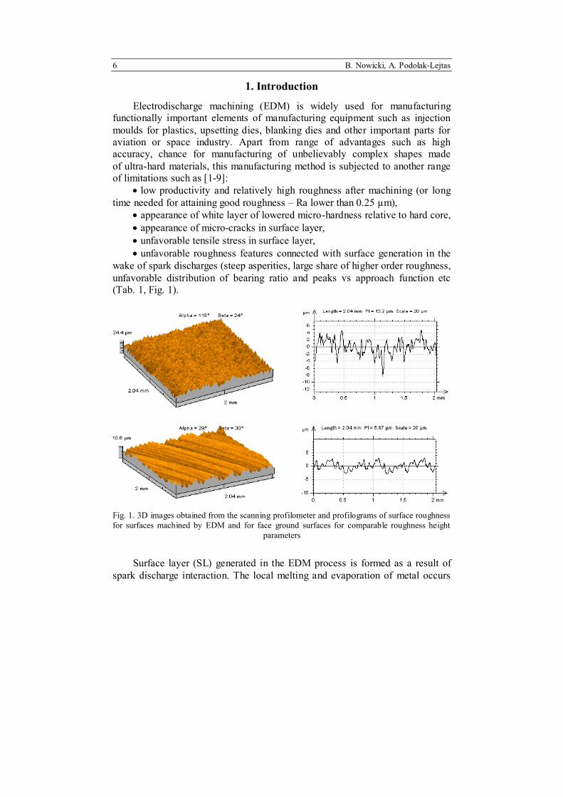
wake of spark discharges (steep asperities, large share of higher order roughness, unfavorable distribution of bearing ratio and peaks vs approach function etc (Tab. 1, Fig. 1).
Fig. 1. 3D images obtained from the scanning profilometer and profilograms of surface roughness for surfaces machined by EDM and for face ground surfaces for comparable roughness height parameters
Surface layer (SL) generated in the EDM process is formed as a result of spark discharge interaction. The local melting and evaporation of metal occurs
Investigations of surface integrity ... 7
and craters are formed on the machined surface and they are covered by thin layer of molten metal which has not been displaced form a crater.
Strong thermal interaction of spark discharge channel with the surface, solidification of molton metal layer in the crater and ensuing thermal strain are a cause for formation of layer typical for the EDM, with specific microstructure, discontinuity and possible micro-cracks and this layer is changed with respect to core microharness and tensile residual stress.
Table 1. Results of comparative investigations for surface texture of ground and for EDM-ed surface of comparable roughness parameters. 3-D roughness height parameters: Sa, St, slope - SD - Ssc and roughness profile pitch – RSm
Parametrs 3D EDM Grinding Sa [µm] 1.8 1.24 St [µm] 24.4 10.6
The remolten layer is called white layer and, depending on machining
parameters, its depth varies within a few micron to a few tens of micron and it is resistant to etching by typical etching agents. During the investigations carried out by optical microscopes, is visible as white color layer. The examination carried out by TEM have shown [2, 4] that its structure is typical of tiny grain and dendritic, columnar and martensite sublayers occur inside it.
The above mentioned features often contribute to deterioration of performance parameters of the machined elements, notably fatigue resistance, friction coefficient etc [7, 9] (Table 2). It happens that additional manufacturing operations need to follow the EDM in order to compensate for this deterioration or to elevate performance.
There are many cases when abrasive operations are applied after the EDM (abrasive flow machining or abrasive electro-device machining) and surface layer constituted by the EDM is removed and surface smoothness is improved. Another solution consists in shooting the surface with a flux of glass of china balls (a few tens µm in diameter) and it is aimed at improving smoothness and other surface layer characteristics but it is also used in order to remove surface layer obtained after the EDM in part.
In case of machine parts operating under dynamic load, superficial cold work is applied ensuring strain hardening of surface layer, surface smoothing and compressive stress type. For free-form surface manufacturing, shot-peening is applied. Taniguchi [6] has made considerable advances in the field of the in-process burnishing after the EDM using ceramic burnishers.
8 B. Nowicki, A. Podolak-Lejtas
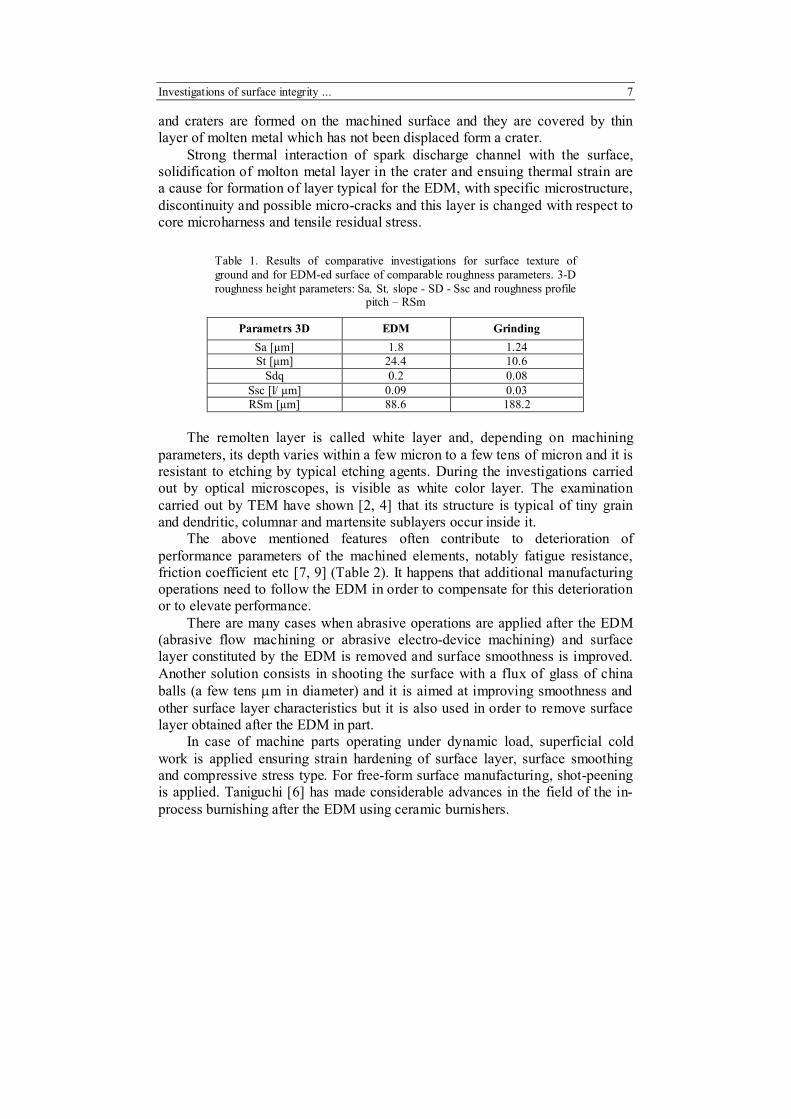
Final surface layer condition after manufacturing process results from three basic phenomena occurring during machining (Fig. 2):
• heat process effecting in tensile stress and micro-cracks in surface layer, • phase changes effecting in new metallographic structure and changes of
state of stress in surface layer, • plastic deformations effecting in compressive stress, crack fading and
structural changes in surface layer.
Table 2. Influence of machining method on fatigue resistance [2]
Moreover, there exist interactions between the above processes. Structural
changes can be connected with the heat emission and deformations may induce structural changes etc.
Fig. 2. Fundamental processes influencing surface layer condition
after machining
Investigations of surface integrity ... 9
Shot-peening is most popular method for quality enhancement of products manufactured by the EDM. Superficial machining by shot peening is the most frequently used method for upgrading quality of parts manufactured by the EDM. The machined surface is struck by a flux of steel or cast iron balls running at speed of several tens of m/s. The balls hit the part surface and they introduce strain hardening and compressive stress [1, 8]. This manufacturing method is expensive, though and it involves the use of big and rare industry installations so that machine parts manufactured by the EDM have not been widely subjected to this technique.
Recently, first publications reporting the results of slide burnishing of the EDM-ed flat surface have been available [6]. The authors of these papers conclude that application of burnishing after the EDM results in roughness reduction and introduction of compressive stress into surface layer. However, there is no published information on application study relating to performance characteristic enhancement of surface layer obtained.
The authors devised new manufacturing technique for superficial cold work of parts which had been subjected to the EDM process. The technique is based on the method elaborated in the Boeing and 3M company which was used for repairing aircraft parts and it employed the roto-peen heads (Fig. 3). The tools for the roto-peen machining are from flap – shaped material basing on fibre-glass matrix with cemented carbide balls of diameter D = 1 mm which are stuck to the matrix using special glue. The roto-peen tools of diameter 30-50 mm rotate at speed 3000-8000 rev/min. which corresponds to rotational speed v = = 4-13 m/s and they dynamically hit machined surface with spherical surfaces (r = 0.5 mm) of hard material, they smoothen micro-irregularities, they strain-harden machined surface and introduce advantageous compressive residual stress. Free-form surfaces can be machined with this process using universal tools and inexpensive equipment (hand-operated pneumatic or electric grinders,
Fig. 3. View of tools used for the roto-peen machining [6]
10 B. Nowicki, A. Podolak-Lejtas
Fig. 4. Influence of static interaction of individual ball of the roto-peen tool on diameter of ball imprint for a sample of HRC49 [6]
0
0,1
0,2
0,3
0,4
0,5
50 100 200 400 600
d [m
m]
Dia
met
er d
, mm
F [N]Force F, N
Fig. 5. 3-D image and profilogram for individual hit of a sample of hardness 34 HRC, developing 400 N force [6]
fixtures, universal measuring instruments). Application of the roto-peen after the EDM is good for reduction of unfavorable heat effect and structural influence (Figs. 4, 5).
2. Research on influence of machining parameters on surface layer condition
Conducted research was aimed at determining the influence of machining conditions for the combined EDM and the roto-peen machining as well as alternative EDM and the roto-peen machining on surface roughness and surface layer condition after machining.
The research on the influence of machining parameters on surface layer (SL) properties was carried out for samples prepared from hardened tool steel NC10 and machined in typical EDM environment ensuring average roughness parameters and then roto-peen machined (Tab. 3) for various machining parameters (head rotational speed, machining time).
EDM machining has been implemented on the ROBOFORM 30 spark erosion center made by Charmilles Technologies, equipped with transistor type generator offering controllable values of the current and spark discharge duration time. The settings applied were typical for productivity-oriented machining or medium accuracy machining. The copper electrodes and kerosene dielectric was used.
Investigations of surface integrity ... 11
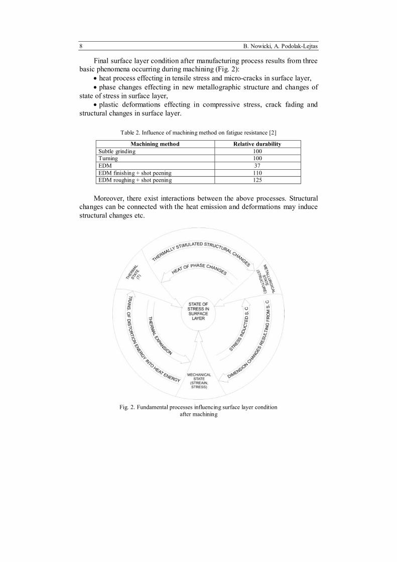
Parameters for the roto-peen machining were selected according to carefully planned and effected experiments. These parameters should be selected so that the strain hardening depth is at least as high as the thickness of re-melted zone and possibly quenched post-EDM zone if such zone ever exists and the depth of residual (compressive) stress after the burnishing should be larger than the stress-affected zone after the EDM. The experiments consisted in carrying out the roto-peen machining for the Almene samples and then measuring strain hardening depth.
Table 3. Comparative presentation of parameters for the EDM and roto-peen machining
EDM parameters roto-peen parameters
sample denotation U [V] I [A] Ti [us] n [rev./min] t [min]
7000 5 Samples for the most important experiments have been machined by the
EDM in typical condition. They showed varying SL depth after machining and varying surface roughness. These samples were subsequently subjected to the roto-peen for various tool rotational speed and various machining time (Table 4).
Surface layer condition after combined EDM+roto-peen machining was assessed basing on the following measurement results:
• surface roughness profiles, • surface micro-stereometry, • surface layer micro-hardness, • surface layer micro-structure tests. Further investigations are scheduled and they will include measurement of
stress in surface layer and fatigue resistance [7, 9].
12 B. Nowicki, A. Podolak-Lejtas
Table 4. Influence of the combined EDM and roto-peen process parameters on surface roughness
Roto-peen parameters
2D micro-geometry roughness
3D micro-geometry roughness
Remelted layer
SL thicknes
s
EDM Process
conditions
n [rev/ min]
t [min]
Ra
[µm] Rp
[µm] RDq
Ssc
[1/µm] STp = 0.1St
[%] w.l [µm] w.l+haz
[µm]
- - 9,96 39,43 16,02 0,24 0,10 35,45 51,88
5000 2,5 5,77 19,09 10,57 0,05 3,60 21,15 41,58
5000 5 5,82 13,66 6,49 0,04 0,50 16,76 35,81
7000 2,5 6,71 16,47 14,19 0,05 0,10 14,36 28,49
EDM U=120 V, I=24 A,
Ti=200 us
7000 5 3,85 11,90 7,29 0,05 0,20 14,23 28,96
- - 21,96 64,16 19,19 0,22 0,70 70,50 -
5000 2,5 12,70 27,09 13,35 0,08 2,80 41,08 67,77
5000 5 7,48 16,57 9,74 0,06 2,37 25,40 42,55
7000 2,5 6,86 16,19 10,23 0,07 2,84 34,99 57,63
EDM U=80 V, I=248 A, Ti=400 us
7000 5 10,28 22,09 11,12 0,05 2,19 35,63 63,94
- - 6,38 14,92 14,53 0,20 0,10 24,22 48,75
5000 2,5 4,63 9,46 5,14 0,03 1,30 15,28 37,21
5000 5 3,38 11,66 6,73 0,04 2,80 29,82 53,97
7000 2,5 7,04 13,20 8,23 0,03 2,26 25,55 53,47
EDM U=80 V, I=48 A,
Ti=400 us
7000 5 1,73 3,82 3,00 0,07 0,50 17,78 37,70 The results of surface layer examination after the EDM are presented in
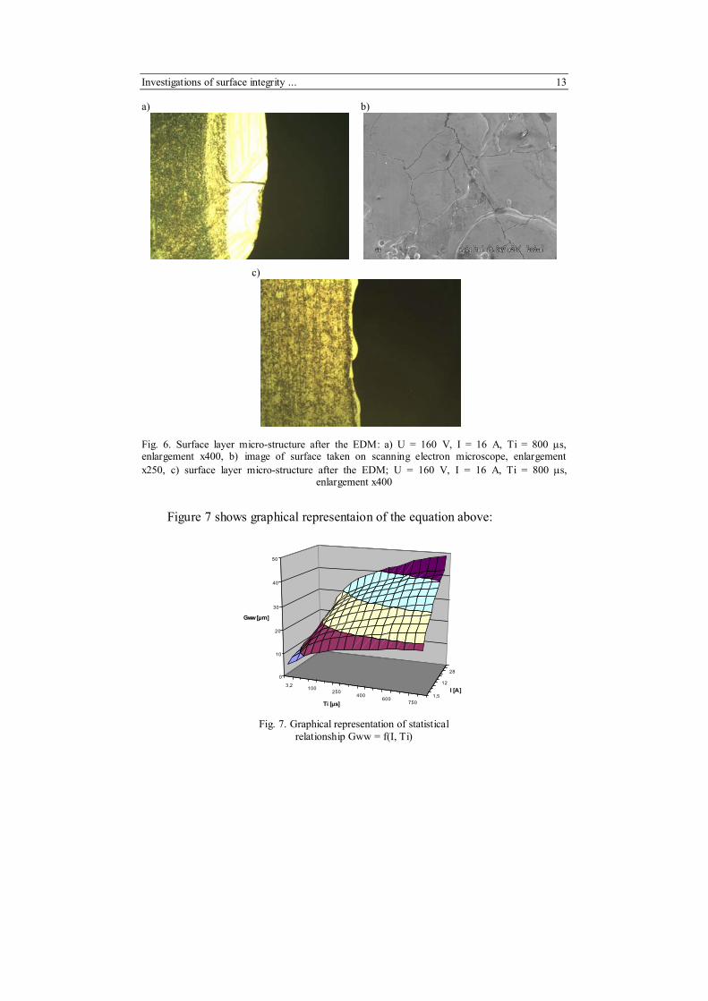
Table 4. Surface roughness Ra after the EDM equals respectively: 3.7; 6.4; 9.96 and 22 µm. Surface layer thickness after the EDM ranges from GEDM = 40 µm to GEDM = 70 µm. The surface layer micro-structure after the EDM is presented in Fig. 6a, c. It is kind of micro-structure for this treatment type, with typical whitened layer, with visible micro-crack and heat-affected zone.
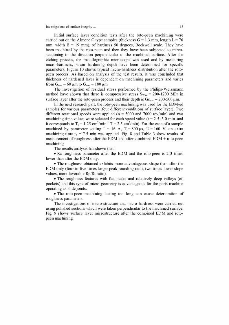
A statistical relationship has been developed basing on data specified in Table 4 between thickness of remolten layer and machining parameters:
Gww (I, Ti) = 3,74 ⋅ I 0,29 ⋅ Ti 0,22
Investigations of surface integrity ... 13
a)
b)
c)
Fig. 6. Surface layer micro-structure after the EDM: a) U = 160 V, I = 16 A, Ti = 800 µs, enlargement x400, b) image of surface taken on scanning electron microscope, enlargement x250, c) surface layer micro-structure after the EDM; U = 160 V, I = 16 A, Ti = 800 µs, enlargement x400
Figure 7 shows graphical representaion of the equation above:
3,2 100250
400600
7501,5
12
280
10
20
30
40
50
Gww [µm]
Ti [µs]
I [A]
Fig. 7. Graphical representation of statistical
relationship Gww = f(I, Ti)
14 B. Nowicki, A. Podolak-Lejtas
a)
b)
c)
d)
e)
Fig. 8. Surface roughness microstereometry and profilograms obtained by scanning profilometers for samaples machined by: a) EDM U = 80 V, I = 48 A, Ti = 400 µs and then roto-peened for the following parameters, b) n = 5000 rev/min, t = 2,5 min, c) n = 5000 rev /min, t = 5 min, d) n = 7000 rev /min, t = 2,5 min, e) n = 7000 rev /min, t = 5 min
Investigations of surface integrity ... 15
Initial surface layer condition tests after the roto-peen machining were carried out on the Almene C type samples (thickness G = 1.3 mm, length L = 76 mm, width B = 19 mm), of hardness 50 degrees, Rockwell scale. They have been machined by the roto-peen and then they have been subjected to mirco-sectioning in the direction perpendicular to the machined surface. After the etching process, the metallographic microscope was used and by measuring micro-hardness, strain hardening depth have been determined for specific parameters. Figure 10 shows typical micro-hardness distribution after the roto-peen process. As based on analysis of the test results, it was concluded that thickness of hardened layer is dependent on machining parameters and varies from Gww = 60 µm to Gww = 180 µm.
The investigation of residual stress performed by the Philips-Weissmann method have shown that there is compressive stress SWW = 200-1200 MPa in surface layer after the roto-peen process and their depth is Gsww = 200-500 µm.
In the next research part, the roto-peen machining was used for the EDM-ed samples for various parameters (four different conditions of surface layer). Two different rotational speeds were applied (n = 5000 and 7000 rev/min) and two machining time values were selected for each speed value (t = 2.5; 5.0 min. and it corresponds to Tj = 1.25 cm2/min i T = 2.5 cm2/min). For the case of a sample machined by parameter setting I = 16 A, Ti = 800 µs, U = 160 V, an extra machining time t3 = 7.5 min was applied. Fig. 8 and Table 3 show results of measurement of roughness after the EDM and after combined EDM + roto-peen machining.
The results analysis has shown that: • Ra roughness parameter after the EDM and the roto-peen is 2-3 times
lower than after the EDM only. • The roughness obtained exhibits more advantageous shape than after the
EDM only (four to five times larger peak rounding radii, two times lower slope values, more favorable Rp/Rt ratio).
• The roughness features with flat peaks and relatively deep valleys (oil pockets) and this type of micro-geometry is advantageous for the parts machine operating as slide joints.
• The roto-peen machining lasting too long can cause deterioration of roughness parameters.
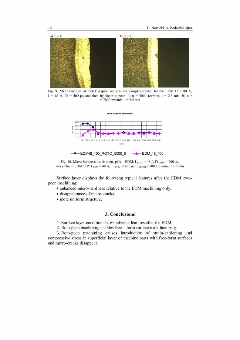
The investigations of micro-structure and micro-hardness were carried out using polished sections which were taken perpendicular to the machined surface. Fig. 9 shows surface layer microstructure after the combined EDM and roto-peen machining.
16 B. Nowicki, A. Podolak-Lejtas
a) x 200
b) x 200
Fig. 9. Microstructure of metalographic sections for samples treated by the EDM U = 80 V, I = 48 A, Ti = 400 µs and then by the roto-peen: a) n = 5000 rev/min, t = 2.5 min, b) n = = 7000 rev/min, t = 2.5 min
Fig. 10. Micro-hardness distribution, pink – EDM: I EDM = 48 A,Ti EDM = 400 µs, navy blue – EDM+RP: I EDM = 48 A, Ti EDM = 400 µs, n ROTO = 5000 rev/min, t = 5 min
Surface layer displays the following typical features after the EDM+roto-peen machining:
• enhanced micro-hardness relative to the EDM machining only, • disappearance of micro-cracks, • more uniform structure.
3. Conclusions
1. Surface layer condition shows adverse features after the EDM. 2. Roto-peen machining enables free – form surface manufacturing. 3. Roto-peen machining causes introduction of strain-hardening and
compressive stress in superficial layer of machine parts with free-form surfaces and micro-cracks disappear.
Investigations of surface integrity ... 17
4. The depth of strain hardening zone and advantageous stress in surface layer can be much larger after the roto-peen machining than typical depth of surface layer for parts machined by the EDM.
5. Application of the roto-peen machining after the EDM enables more advantageous features of surface geometric structure than after the EDM process only.
6. The roto-peen machining after the EDM is possible to effect with simple tools and in ordinary workshop environment.
References
[1] D. ADAMOVIC, M. BABIC, B. JEREMIC: Shot peening influence on tribological characteristic of surfaces. Proc. the 7 th Int. Conf. on the Shoot Peening, Institute of Procession Mechanics. Warsaw, 350-358.
[2] G. CUSANELLI, A. HESSLER-WYSER, F. BOBARD, R. DEMELLAYER, R. PEREZ, R. FLUKIGER: Microstructure at submicron scale of the white layer produced by EDM machining. Proc. XIV ISEM. Edinburgh 2004, vol. 149, 289-295.
[3] J. GRUM: Residual stress and fatigue strength after strain Hardening of steel. Metal Finishing News, 6(2005), 36-38.
[4] J. P. KRUTH, J. Van HUMBEECK, L. STEVENS: Micro structural investigation and metallographic analysis of the white layer of a structure machined by electro-discharge machining. Proc. XI ISEM. Lausanne 1995, 849-862.
[5] D. KIRK: Residual stresses in shot peened components, The Shot Peener, Fall 2004, 24-28.
[6] Y.C. LIN, B.H. YAN, F.Y. HUANG: Surface improvement using a combination of electrical discharge machining with ball burnish machining based on the Taguchi method. Journal of Advanced Manufacturing Technology, 18(2001), 673-682.
[7] D.A. LUCCA, E. BRINKSMEIER, G. GOCHE: Progress in assessing surface and subsurface integrity. Proc. 48th CIRP General Assembly, Athens 1998, 669-693.
[8] V. SCHULZE: Characteristics of surface layers produced by shot peening. Proc. the 8 th Inter. Conf. on the Shoot Peening, Garmische-Partenkirchen 2002, 145-160.
[9] T. TAMURA: Surface modification of cemented carbides machining by electrical discharge machining using oxidizing treatment – explanation of the removal mechanism of oxidized layer. Proc. XIII ISEM. Bilbao 2001, 685-694.


![j kZ e vg Z y g Z mqg Z y · г < h e h ]h ^ kdZ y h [ e Z klg Z y mg b \ _ j kZ e vg Z y g Z mqg Z y [ b [ e b h l_ dZ](https://static.documents.pub/doc/80x56/5fc0961458b1c478742c70a7/j-kz-e-vg-z-y-g-z-mqg-z-y-h-e-h-h-kdz-y-h-e-z-klg-z-y-mg-b-j-kz.jpg)


![n Z a Z II k Z Q Z l b g Z g Z k g h ] j ] m e Z p b ] g j Z e g i e Z g Z G Z p j l · 2018-10-15 · ] j Z g b p Z h [ m o \ Z l Z I e Z g Z d Z l Z k l Z j k d Z i h ^ e h ] Z](https://static.documents.pub/doc/80x56/5f460278c53c820b06268147/n-z-a-z-ii-k-z-q-z-l-b-g-z-g-z-k-g-h-j-m-e-z-p-b-g-j-z-e-g-i-e-z-g-z-g-z-p.jpg)


