PROJECTS & DEVELOPMENT INDIA LIMITED ITS NO: PC00037/PVMM/ENQ/0801/L-02 for supply cum E&C of Permanent Cathodic Protection System PC00037-PVMM-0012 0 DOCUMENT NO REV SHEET 1 OF 2 ONGC URAN TO BPCL URAN U/G LPG PIPELINE, jPROJECT-PC000371 INVITATION TO BID (NATIONAL COMPETITIVE BIDDING) ITB NO: PC00037/PVMM/ENQ/0801/L-02 FOR Supply cum Erection & Commissioning of Permanent Cathodic Protection System ISSUED BY PROJECTS & DEVELOPMENT INDIA LTD., BARODA (CONSULTANT) ON B·EHALF OF BHARAT PETROLEUM CORPORATION LIMITED (OWNER) 'A' Installation, Sewree Fort Road, Sewree (East) Mumbai-400015 o REV 05.12.2012 REV DATE 05.12.2012 EFF DATE For Implementation PURPOSE PREPD FORM NO: 02-0000-0021 F1 REV1 All rights reserved
Transcript
PROJECTS & DEVELOPMENT INDIA LIMITED
ITS NO: PC00037/PVMM/ENQ/0801/L-02 for supply cum E&C of Permanent Cathodic Protection System
PC00037-PVMM-0012 0
DOCUMENT NO REV
SHEET 1 OF 2
ONGC URAN TO BPCL URAN U/G LPG PIPELINE, jPROJECT-PC000371
INVITATION TO BID (NATIONAL COMPETITIVE BIDDING)
ITB NO: PC00037/PVMM/ENQ/0801/L-02
FOR Supply cum Erection & Commissioning of Permanent Cathodic
Protection System
ISSUED BY
PROJECTS & DEVELOPMENT INDIA LTD., BARODA (CONSULTANT)
ON B·EHALF OF
BHARAT PETROLEUM CORPORATION LIMITED (OWNER)
'A' Installation, Sewree Fort Road, Sewree (East) Mumbai-400015
o REV
05.12.2012 REV DATE
05.12.2012 EFF DATE
For Implementation PURPOSE PREPD
FORM NO: 02-0000-0021 F1 REV1 All rights reserved
FORM NO: 02-0
DO
PC000
PC0
PC0
PC0
PC0
PC0
PC0
PC0
PC0
PC0
PC0003
PC0003
PC0003
PC0003
PC0003
PC0003
PC0003
PC0003
PC0003
PC0003
PC0003
ITB NO: PC
0000-0021F2 RE
OCUMENT
037-PVMM-00
00037-PVMM
00037-PVMM
00037-PVMM
00037-PVMM
0037-PVMM-
0037-PVMM-
00037-PVMM
00037-PVMM
00037-PVMM
7-PVMM-A06
7-PVMM-A06
7-PVMM-A06
7-PVMM-A06
7-PVMM-A06
7-PVMM-A06
7-PVMM-A06
7-PVMM-A06
7-PVMM-A06
7-PVMM-A06
7-PVMM-A06
COINVITA
C00037/PVMM/ENQCath
V1
NO.
012-ITB C
M-F02 A
M-A01 A
M-A02 A
M-A03 A
-A03A S
-A03B S
M-A04 A
M-A05 A
M-A06 A
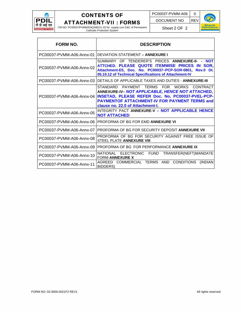
6-Annx-01 D
6-Annx-02 SA
6-Annx-03 D
6-Annx-04
SAIPc
6-Annx-05 IA
6-Annx-06 P
6-Annx-07 P
6-Annx-08 PS
6-Annx-09 P
6-Annx-10 NA
6-Annx-11 A
NTENTS ATION TOQ/0801/L-02 for suodic Protection Sys
COVERING
ACKNOWLE
ATTACHME
ATTACHME
ATTACHME
SPECIAL CO
SPECIAL CO
ATTACHME
ATTACHME
ATTACHME
DEVIATION S
SUMMARY APPLICABLE
DETAILS OF
STANDARD ANNEXURE-INSETAD,
PAYMENTOclause no. 2NTEGRITY P
ATTACHED
PROFORMA
PROFORMA
PROFORMA STEEL PLAT
PROFORMA
NATIONAL EANNEXURE X
AGREED CO
OF O BID upply cum E&C of stem
LETTER OF
EDGEMENT
ENT-I - INST
ENT-II - GEN
ENT-III – SPE
NDITIONS O
NDITIONS O
ENT-IV – TE
ENT-V - SAF
ENT-VI - FOR
STATEMENT
OF TENDEE, HENCE NO
APPLICABLE
PAYMENTIV – NOT PLEASE R
OF ATTACH22.0 of AttacPACT ANNE
OF BG FOR
OF BG FOR
OF BG FOE ANNEXUR
OF BG FOR
ELECTRONICX
MMERCIAL T
Permanent
P
DESCRIP
F INVITATIO
T OF ITB
TRUCTIONS
NERAL CON
ECIAL CON
OF CONTRAC
OF CONTRAC
CHNICAL S
FETY REQU
RMS
T – ANNEXUR
ERER’S PROT ATTACHE
E TAXES AN
T TERMS APPLICABL
REFER DocHMENT-IV Fchment-I. XURE-V - N
EMD ANNEX
SECURITY D
OR SECURITRE VIII
PERFORMA
C FUND TRA
TERMS AND
PC00037-PVMM-
DOCUMENT N
SHEET 2
PTION
ON TO BID
S TO BIDDER
NDITIONS O
NDITIONS O
CT-PART-A
CT-PART-B
SPECIFICAT
IREMENTS
RE I
RICES ANNED
D DUTIES - A
FOR WOLE, HENCE c. No. PCFOR PAYM
NOT APPLICA
XURE VI
DEPOSIT AN
TY AGAINST
ANCE ANNEX
ANSFER(NEF
CONDITION
-0012 0
NO REV
OF 2
All
RS
OF TENDER
F CONTRAC
TIONS
W.R.T. HSE
NEXURE-II
ANNEXURE-
ORKS CONNOT ATTA
C00037-PVEMENT TERM
ABLE, HENC
NNEXURE VII
T FREE ISS
XURE IX
T)MANDATE
NS
rights reserved
CT
E
- NOT
-III
NTRACT TACHED,EL-PCP-MS and
CE NOT
SUE OF
E FORM-
-
FORM NO: 02-0
---------------TO
PLEASE BID TO PD
SUBM
DGM (EnBHARAT‘A’ INSTASEWREESEWREEMUMBAI
____1.0 Bhara
laying
2.0 Projeappoieligib
INITB NO: P
0000-0021F2 REV
PROJE
---------------
SEND BIDDIL VADOD
ISSION
ngg.) -WEST PETROLEALLATIONE FORT ROE (EAST), I -400 015
INVITATION TO BID ITS NO: PC00037/PVMM/ENQ/0801/L-02 for supply cum E&C of
Permanent Cathodic Protection System
PC00037-PVMM-0012-ITB 0
DOCUMENT NO REV
SHEET 2 OF 2
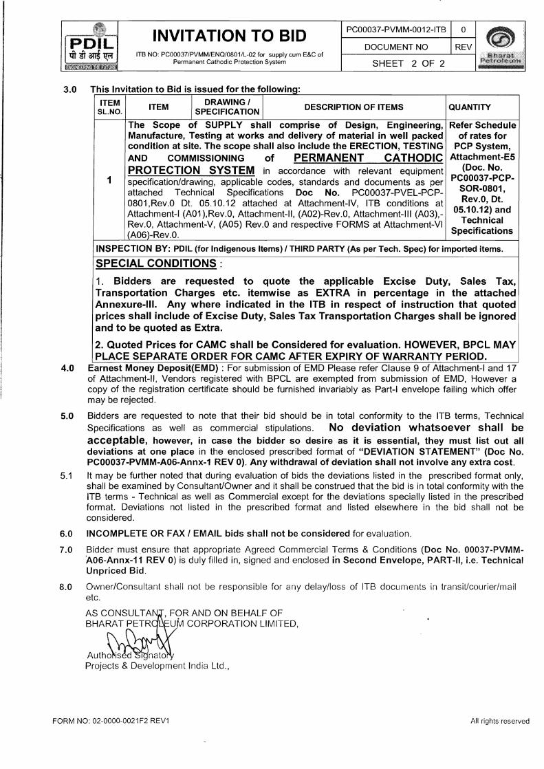
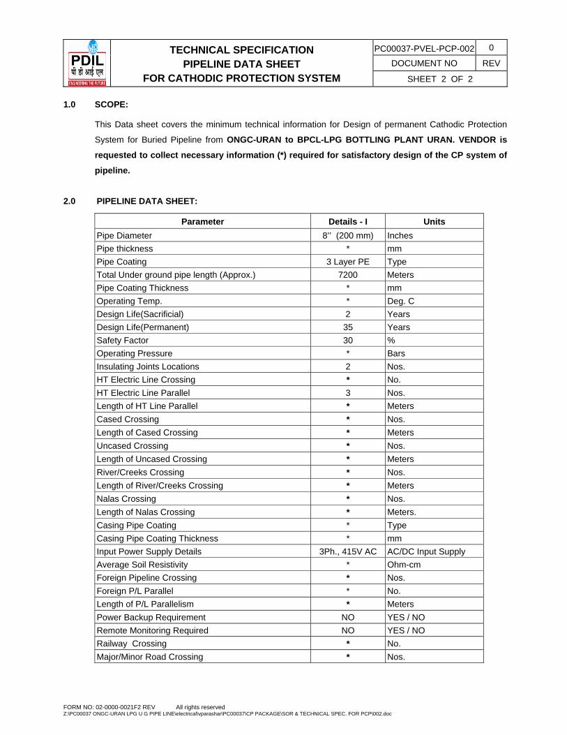
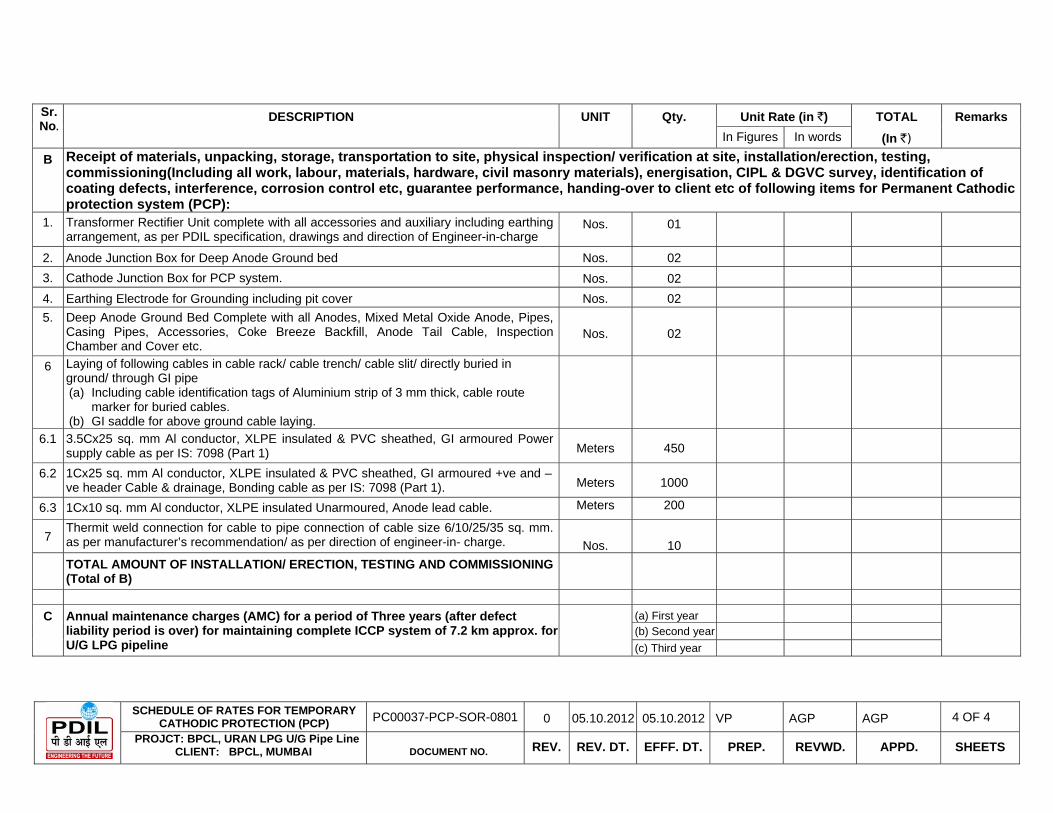
3.0 This Invitation to Bid is issued for the following:
ITEM DRAWING I IITEM DESCRIPTION OF ITEMS QUANTITYSL.NO. SPECIFICATIONI
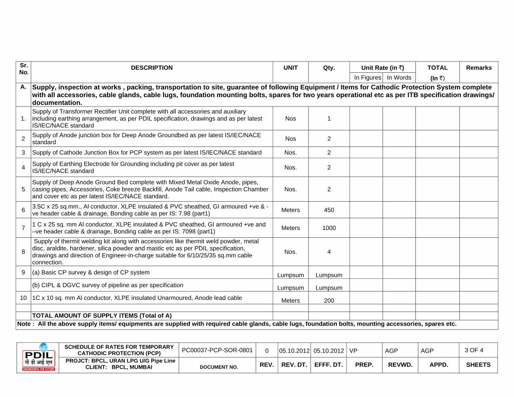
The Scope of SUPPLY shall comprise of Design, Engineering, Refer Schedule Manufacture, Testing at works and delivery of material in well packed of rates for condition at site. The scope shall also include the ERECTION, TESTING PCP System, AND COMMISSIONING of PERMANENT CATHODIC Attachment-E5
(Doc. No. PROTECTION SYSTEM in accordance with relevant equipment PC00037-PCP1 specification/drawing, applicable codes, standards and documents as per
SOR-0801,attached Technical Specifications Doc No. PC00037-PVEL-PCPRev.O, Dt. 0801,Rev.0 Dt. 05.10.12 attached at Attachment-IV, ITB conditions at
05.10.12) and Attachment-I (A01 ),Rev.O, Attachment-II, (A02)-Rev.0, Attachment-III (A03),TechnicalRev.O, Attachment-V, (A05) Rev.O and respective FORMS at Attachment-VI
Specifications(A06)-Rev.0.
INSPECTION BY: PDIL (for Indigenous Items) I THIRD PARTY (As per Tech. Spec) for imported items.
SPECIAL CONDITIONS:
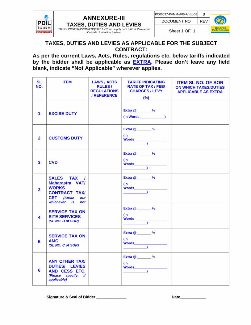
1. Bidders are requested to quote the applicable Excise Duty, Sales Tax, Transportation Charges etc. itemwise as EXTRA in percentage in the attached Annexure-III. Any where indicated in the ITB in respect of instruction that quoted prices shall include of Excise Duty, Sales Tax Transportation Charges shall be ignored and to be quoted as Extra.
2. Quoted Prices for CAMC shall be Considered for evaluation. HOWEVER, BPCL MAY PLACE SEPARATE ORDER FOR CAMC AFTER EXPIRY OF WARRANTY PERIOD.
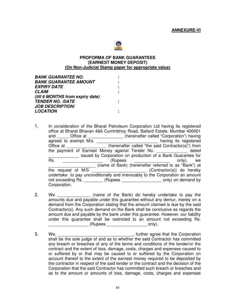
4.0 Earnest Money Deposit(EMD) : For submission of EMD Please refer Clause 9 of Attachment-I and 17 of Attachment-II, Vendors registered with SPCL are exempted from submission of EMD, However a copy of the registration certificate should be furnished invariably as Part-I envelope failing which offer may be rejected.
5.0 Bidders are requested to note that their bid should be in total conformity to the ITS terms, Technical Specifications as well as commercial stipulations. No deviation whatsoever shall be acceptable, however, in case the bidder so desire as it is essential, they must list out all deviations at one place in the enclosed prescribed format of "DEVIATION STATEMENT" (Doc No. PC00037-PVMM-A06-Annx-1 REV 0). Any withdrawal of deviation shall not involve any extra cost.
5.1 It may be further noted that during evaluation of bids the deviations listed in the prescribed format only, shall be examined by ConsultanUOwner and it shall be construed that the bid is in total conformity with the ITS terms - Technical as well as Commercial except for the deviations specially listed in the prescribed format. Deviations not listed in the prescribed format and listed elsewhere in the bid shall not be considered.
6.0 INCOMPLETE OR FAX I EMAIL bids shall not be considered for evaluation.
7.0 Bidder must .ensure that appropriate Agreed Commercial Terms & Conditions (Doc No. 00037-PVMMA06-Annx-11 REV 0) is duly filled in, signed and enclosed in Second Envelope, PART-II, i.e. Technical Unpriced Bid.
8.0 Owner/Consultant shall not be responsible for any delay/loss of ITS documents in transiUcourier/mail etc.
AS CONSULTAN ,FOR AND ON BEHALF OF BHARAT PETR ~ UM CORPORATION LIMITED,
1.0 C 2.0 A 3.0 L 4.0 D 5.0 S 6.0 B 7.0 B 8.0 C 9.0 E10.0 F11.0 L12.0 M13.0 O14.0 P15.0 E16.0 C17.0 L18.0 S19.0 D20.0 E21.0 V22.0 P
ATTACTRUCTIOPC00037/PVMM/E
Permanent Ca
V1
Clarification oAmendment Language of Documents cSubmission oBid Price Bid CurrencieCENVAT/VAEarnest MonFormat and SLate Bids ModificationsOpening andPreliminary EEvaluation anContacting OLetter of InteSigning of PuDelivery Exceptions Vendor's DatPayment Ter
CHMENTON TO BENQ/0801/L-02 for athodic Protection S
INDE
of Bidding Dof Bidding DBid
comprising thof Bid/Tende
es AT
ey Deposit (Signing of B
s and Withdrd ClarificationExaminationnd Comparis
OWNER/CONnt(LOI)/Fax urchase Ord
ta rms
T - I BIDDERS
supply cum E&C oSystem
NDEX ESCRIPTION
Documents Documents
he Bid er
(EMD) id
rawal of Bidsn of Bids
son of BidsNSULTANTof Intent(FO
der
S of
PC000
DOC
SH
N OF ARTIC
s
OI)
037-PVMM-A0
CUMENT NO
HEET 2 OF
CLES
01 0
REV
11
All rrights reserved
2
2
2
2
2
3
3
3
4
4
4
4
4
4
FORM NO: 02-0
1.0 C
PinTth
2.0 A
2.1 Awm
2.2 Tre
2.3 Inins
2.4 Oarw
3.0 L
3.1 Tblalain
3.2 Mpe
4.0 D
4.1 Tin
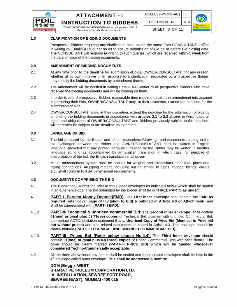
4.1.1 Prs
4.1.2 P0abc
4.1.3 Pccc
4.2 A4
DB‘AS
INSTITB NO:
0000-0021F2 REV
CLARIFICATI
Prospective Bn writing by EThe CONSULhe date of iss
AMENDMENT
At any time pwhether at itsmay modify th
The amendmeeceived the b
n order to affon preparing thsubmission of
OWNER/CONamending theights and obl
will thereafter
LANGUAGE O
The bid prepabid exchangeanguage, proanguage so nterpretation
Metric measupiping connecetc., shall con
DOCUMENTS
The Bidder shn an outer en
PART-I- Earrequired (refeshall be super
PART-II- Tec01(one) origiappropriate Abut without pclearly marked
PART-III - Pcontain 01(oncover should considered T
All the three a4th envelope c
DGM (Engg.BHARAT PEA’ INSTALL
SEWREE (E
ATTACTRUCTIOPC00037/PVMM/E
Permanent Ca
V1
ION OF BIDD
Bidders requirEmail/FAX/CoLTANT will ressue of the bidd
T OF BIDDIN
rior to the des own initiativhe bidding doc
ent will be nobidding docum
ord prospectiheir bids, OWf bids.
NSULTANT m bidding doculigations of Obe subject to
OF BID
ared by the Bed between ovided that an
long as accof the bid, the
rement systections. All pipform to ASA
S COMPRISIN
hall submit thvelope. The B
rnest Moneyer cover pagrscribed with
chnical & unal plus 03(CTC, deviatioprices) and ad (PART-II TE
riced Bid ne) original p
be clearly Techno-Comm
above inner ecalled outer en
.) -WEST ETROLEUMLATION, SEEAST), MUM
CHMENTON TO BENQ/0801/L-02 for athodic Protection S
DING DOCUM
ring any clarifourier so as tspond in writiding docume
NG DOCUMEN
eadline for suve or in respocuments by a
otified in writinments and wil
ve Bidders reWNER/CONSU
may, at their duments in acc
OWNER/CONo the deadline
Bidder and althe Bidder any printed litecompanied be English tran
em shall be aping material dimensional r
NG THE BID
e offer in threBid submitted
y Deposit(Ege of Invitati(PART- I EM
unpriced co(Three) copieon statement also related dECHNICAL A
(Refer beloplus 03(Thre
marked (PAmercially acc
envelopes shanvelope. This
CORPORAWREE FOR
MBAI -400 01
T - I BIDDERS
supply cum E&C oSystem
MENTS
fication shall o ensure subng to such qunts.
NTS
bmission of bonse to a cla
amendment th
ng Email/FAXl be binding o
easonable timULTANT may
iscretion, extecordance withSULTANT an
e as extended
l correspondeand OWNERerature furnisy an English
nslation shall
applied for wincluding butrequirements
ee inner enved by the Bidde
EMD): The Fion to Bid) &D).
ommercial Bes of Technicif any, Unpri
documents asAND UNPRIC
ow clause e) copies of
ART-III PRICceptable.
all be sealed s shall be ad
ATION LTD.RT ROAD, 15
S of
PC000
DOC
SH
obtain the sabmission of Bueries, which
bids, OWNERarification reqhereto.
X/Courier to aon them.
me required toy, at their disc
end the deadh articles 2.1nd Bidders prd.
ence/drawingR/CONSULTA
hed by the Bh translation govern.
weights and dt not limited t.
elopes as inder shall be in T
First inner en& outlined in
Bid: The Seccal Bid togethiced Copy ofs stated in Ar
and shall be00037”, ITB NThe outer enveturned unopf the outer en
assume no re
PART-II - TECextent applica
Technical Bid
a) ITB No.b) Docume
the Biddc) Comple
catalogud) List of se) List of m) Layout
limits ofg) Bidder s
materiathe man
h) Bidder smainten
) Nature o) Deliveryk) Manufac
guarantraw mat
) Referenm) Complen) Informa
heavy ao) Training
Unpriced com
TB No. _____
a) Unpriced
b) Terms of
c) Confirmat
d) Delivery p
e) Acceptanc
) Confirmat
g) Indian Bid
h) Country o
) FOT/FOR
ATTACTRUCTIOPC00037/PVMM/E
Permanent Ca
V1
ear the title NO: _______velope shall
pened in casenvelope is nosponsibility fo
CHNICAL & Uable:
d :
. __________entary evidender conform toete scope ofues, etc. as aspare parts asmaintenance tdrawings andf supply, whershall state thels which is nonufacturer to sshould certify nance after insof maintenancy schedule ancturer's scheeed delivery terials, fabricance list of custete data sheettion on shipp
and oversize pg facilities offe
mmercial Bid
___________
copy of PA
payment;
tion that firm p
period to be re
ce of general
tion that valid
dders shall qu
of origin of Go
R place of disp
CHMENTON TO BENQ/0801/L-02 for athodic Protection S
“ONGC UR___& “DO NOindicate the
e it is declaredot sealed and or the bid mis
UNPRICED C
___________nce establishio the bidding f supply su
applicable. s per requiremtools and matd sketches wrever applicabe names of thot of his own supply such Gthat they will
stallation at Sce assistance
nd place of maedule: A brief
separately foation, inspecttomers using ts as requireding weights apackages. ered.
d:
__________ D
RT-III BID
prices have b
eckoned with
conditions of
ity of Bid is fo
uote Delivery
oods and serv
patch (Indian
T - I BIDDERS
supply cum E&C oSystem
RAN TO BPCOT OPEN BEname and ad
d “LATE / DELmarked as r
placement or
COMMERCIA
_____ Due Dang that the Gdocuments.pported by
ment of Technterials, lubricaith (approximble.
he sub-manufamanufacture
Goods in Indial give shop dr
Site. Reprodue available/offanufacture/def statement oor each categtion, testing scsimilar equip
d by OWNER/and cubage (le
Due Date: ___
been quoted ti
date of issua
f purchase.
or 180 Days f
Period FOR
vices.
Vendor)
S of
PC000
DOC
SH
CL URAN U/FORE BID Cddress of theLAYED”. required abor premature o
AL BID shall in
ate: ________Goods and an
drawings, d
nical Specificaation schedule
mate) dimensio
acturers prope and establisa. rawings of macible of 'as bfered by Biddelivery. of the activitigory of equipmchedule etc. j
pment comple/CONSULTANength, width a
___________
ill pendency o
ance of LETTE
from the Bid
R/FOT destina
037-PVMM-A0
CUMENT NO
HEET 4 OF
/G LPG PIPLOSING DAT
e Bidder to e
ove, OWNER pening.
nclude/indicat
_________ ncillary servic
ocuments, b
ation, if any. e, wherever aons of equipm
posed for evesh that Bidder
ain equipmenbuilt' drawingsder.
es and time ment. For exajustifying the
ete with perforNT. Indicate tand height) w
____
of the order.
ER/FAX OF I
Closing date
ation, BPCL
01 0
REV
11
All r
PELINE, PROTE’’.
enable the bid
/ CONSULTA
te the followin
ces to be sup
brochures, s
applicable. ment and ind
ry equipmentr is duly auth
nt to enable res shall be furn
estimation leample: procurguaranteed drmance statustime of submi
with special at
NTENT.
e.
Uran site bas
rights reserved
OJECT-
d to be
ANT will
ng to the
pplied by
tandards,
ication of
t/item and orised by
epair, and nished.
eading to rement of delivery. s. ission. ttention to
sis.
4
5
5
5
5
5
5
5
5
5
FORM NO: 02-0
4.4 PPAQ0
5.0 S
5.1 BinocPc
5.2 Besvinctetop
5.3 Tsqth
5.4 Itsthbs
5.5 Bpmes
5.6 Uthac
5.7 Tmcawdscaw
5.8 Toath
INSTITB NO:
0000-0021F2 REV
PART-III : PrPart- III PriceArticle 9.0 andQUOTED in S05.10.12 of Te
SUBMISSION
Bidder shall cn respect of open conditiocase ONLY PPriced Bid" scorresponde
Before submiexamine and soil, state of lvarious constntended by thcivil works anender may beo make any c
point of time a
The Tenderersufficiency of quantities whihe contract.
t must be clestrictly enforcehey are clear
been so ordeshall be final
Before filling procured andmay be desentertained onshall not be ar
Unless specifihe Tender rat
actual complecost of labour
The Rates qumaterials, trcharges, priceagreed to be swhich case, tdeducted befoschedule of qcarriage and cand all other works
The contractooutside and ina neat and tidyhose agreed
ATTACTRUCTIOPC00037/PVMM/E
Permanent Ca
V1
iced Bid : The Bid. Bid sd appropriateSchedule of echnical Spe
N OF BID/TEN
complete the bbid documenon as well a
Priced Bid is such Offers snce with the
tting the Tensatisfy as to and and of thtruction and he OWNER and for drinkinge accepted anclaim on any oand such a cla
r shall be deehis tender f
ch rates and
early understoed and that nly outside the
ered in writingand binding.
the Tender d the schedulesired by thn this accountrbitrable.
ically providetes or prices
etion of the jor or due to an
uoted by the ransportation e escalationssupplied by Ohe cost of suore making pquantities shcartage, carryexpenses ne
or shall makenside the wory condition afto be supplie
CHMENTON TO BENQ/0801/L-02 for athodic Protection S
he price bid sshould includee Price Sched
Rates, Attacecifications o
NDER
bid documentnts. In case eas the Priced
submitted, oshall be SUM Vendor.
nder, the Tenthe nature of
he excavationother materia
and shall alsog purpose annd with whomof the said coaim shall not
emed to havefor the work
d prices shall
ood that the wno work will be scope, spirig by Owner
the Contractoe of quantitiese Tenderert, after submi
d for in the tequoted will b
ob whichever ny other reaso
Tenderer sh of machin
s, profits, etcOwner and meuch material payment of t
hall unless otying in and reecessary in
e all arrangeking places fofter completiod by the Own
T - I BIDDERS
supply cum E&C oSystem
shall be subme the Bid pric
dule formats achment-E5, Dof Attachmen
ts as per aboeither (a) the d offer in opor (c) Price iMMARILY RE
nderer shall f existing roans, the correcal and their
o satisfy of thend power reqm the contractounts in what be raised as
e satisfied fks and of thel except as ot
whole of the e consideredit, meaning ofand/or Engin
or will checks by obtainingr. No claim ssion of Tend
ender documbe permitted t
is later on aons. Claims o
hall include e(s), tools,
c. etc. exceptentioned spec if taken for the Bill(s) of therwise stat
eturn of emptiand for the
ements at hisor erection & on of the job tner shall be su
S of
PC000
DOC
SH
mitted in a sece and otherattached with Doc. No. PCnt-IV.
ove Article 4.0Vendor suben conditions mentioned
EJECTED, W
at their own ads, means ofct dimensionsavailability fo
e availability ouired for fabrt is entered inso ever manna dispute and
fully before tee rates and therwise prov
conditions and as extra wof the Contractneer-in-Charg
k and satisfy g clarification
for any allegder by the Te
ents or any Sthroughout theccount of anyn account of
Costs and ex equipment
t to the extencifically in thapreparation othe Contrac
ted be held es, hoisting, full and com
s own cost tCommissionto the satisfacupplied by the
037-PVMM-A0
CUMENT NO
HEET 5 OF
eparate sealer related costthe documen
C00037–PCP-
0 and indicatebmits both thn in the samd in the enve
WITHOUT ANY
cost and exf communicas of the work or the execuof suitable warication work nto shall not bner for what sd shall not be
endering as tprices quote
vided cover al
nd specificatioork and allowet and intent o
ge/Site-in-Cha
all drawingsn from the Owged loss or nderer/Contra
Special Condie period of coy variation in escalation sh
xpenses on ts, labour, nt of the costt regard in coof the Contr
ctor. The deto include wsetting, fittingplete executi
o transport ting job and lection of Ownee contractor a
01 0
REV
11
All r
ed Envelopets, in accordant. PRICES M-SOR-0801, R
e the list of ahe Un-Priced
me envelope, elope markedY reference t
xpenses visit tions, characfacilities for
ution of the water for constetc. Tendere
be eligible anso ever reasoarbitrable.
o the corrected in the schll his obligatio
ons are intended and paid ff the Owner a
arge, whose
s and materiawner on all the
compensatioactor and suc
itions, no escontract or the
prices of mahall not be arb
all counts vizpower, Admit of material(sondition of Coractor's Bill(s)escription givewastage on mg and fixing inion and com
the required eaving the preer. All materiaat his own cos
rights reserved
e marked ance with MUST BE Rev.0 Dt.
annexures d offer in
or (b) in d as "Un-to and/or
the site, cter of the procuring works as truction of er, whose d be able
ons at any
tness and hedule of ons under
ded to be for unless and have e decision
als to be e items as on will be ch a claim
calation in period of
aterials or bitrable.
z. cost of inistration s), if any, ontract, in ) shall be en in the materials, n position pletion of
materials emises in als except st and the
5
6
6
6
6
66
6 7
8
9
9
FORM NO: 02-0
ras
5.9 Tressc
6.0 B
6.1 Td
6.2 F
B0Sqap
6.3 IninN
Tfe
6.4 F6.4.1 P
pcb
6.4.2 B
7.0 B7.1 P7.2 In
8.0 C
Oin(pscs
Itp
Cs
9.0 E
9.1 Tp
INSTITB NO:
0000-0021F2 REV
ates quoted statutory levieThe Contractoegulations an
sufferance casolely responsclaims arising
BID PRICE
The Bidders documents.
For Supply-c
Bidders shall 0801, Rev.0 Specificationsquantities menactual quantitper SOR exce
ndian Biddendicated in thNo extra paym
The inspectionees shall not
Fixed Price Prices quotedperiod of bid contractually abe treated as Bidder will als
BID CURRENPayment shalndian bidder
CENVAT/VAT
OWNER wounvolved in thePart-II), the it
purpose of avstructure. Thecredit purposeshall not be pa
t is to be notpaid including
CENVAT credshall not be c
EARNEST MO
The bidder shpage of ITB. E
ATTACTRUCTIOPC00037/PVMM/E
Permanent Ca
V1
by the Cones, if any, etcor shall be bnd other statuaused due to sible for the sfrom the sam
shall compl
cum-Erection
quote PricesDt. 05.10.1
s for Supply,ntioned in SOies supplied
ept Freight & a
ers (FOR IMhe Tender/Tecment shall be
n for Indigenbe payable.
d by the Biddevalidity and
agreed delivenon-responsio be respons
NCIES l be made in trs shall quot
T (For Indian
ld like to ave project. All tems for whicvailing MVATe bidders shae and in caseayable
ted that Cont Tax Invoice
dit towards considered f
ONEY DEPO
hall furnish asEMD shall be
CHMENTON TO BENQ/0801/L-02 for athodic Protection S
ntractor shou. etc. bound to follutory rules ap
non-observasame and sh
me.
lete the app
n & Commiss
s in Schedule2 of Techn Erection &
OR are tentativand work exeand statutory
PORTED ITEchnical specifmade in this
nous items o
er shall be fixexecution o
ery/completioive and reject
sible for obtain
the currenciete for material
Bidders):
vail the credbidders are rch necessaryT credit by Oall be response the same is
ractor shall bby them to th
Excise Dutyor evaluation
SIT (EMD)
s part of theifurnished as
T - I BIDDERS
supply cum E&C oSystem
uld be inclusi
low and enspplicable to thance of suchhall keep the
propriate PR
sioning Pack
e of Rates Anical Specifi
Commissionve and not biecuted. Henctaxes & dutie
EMS) shall afication and Frespect.
f Indian Bidd
xed and not sof the purchan period onlyted. ning shipping
es and amounls and service
dit/benefit towrequired to indy documents iOwner alongwsible to ensus not received
be required toe concerned
y and Set offn.
r bid an EMDbelow :
S of
PC000
DOC
SH
ve of all roy
sure complianhe area. In t rules and reOwner indem
RICE SCHED
kage and AM
Attachment-Ecations of ning as well nding on buy
ce, bidder shaes.
arrange ThirdFee/Charges
ders shall be
subject to anyase order exy. A bid subm
clearance at
nts in which thes in Indian R
wards MVATdicate, in the in the name owith percentare submissiod, the MVAT
o submit the authorities of
f towards Se
D. The amou
037-PVMM-A0
CUMENT NO
HEET 6 OF
yalties, rents,
nce to all thehe event of aegulations, thmnified again
DULE FORM
C:
E5, Doc. No. Attachment-as AMC. B
er. BPCL will all quote item
d Party Inspeshall be inclu
carried out b
y escalation wxcept statutormitted with an
the port of sh
he Bid prices Rupees (INR)
T on variousTechno-Comof Owner canage of MVATn of eligible component c
documentaryf the Owner to
ervice Tax is
unt shall be a
01 0
REV
11
All r
taxes, dutie
e safety andany damage ohe contractorst all such lo
M, attached
PC00037–PC-IV as per T
Bidder shall make payme
mwsie prices s
ection by theuded in the ba
by PDIL and in
whatsoever dry variation wn adjustable p
hipment, if req
have been stonly.
s goods and mmercial Unpn be furnisheT as per presdocuments foclaimed by th
y evidences foo Claim VAT
s not applica
as indicated
rights reserved
es, octroi,
d security or loss or r shall be osses and
to these
CP-SOR-Technical note that ent as per strictly as
e Agency ase price.
nspection
during the within the price may
quired.
ated.
services riced Bid d for the sent Tax or MVAT he bidder
or MVAT benefit.
able and
in cover
9
9
9
9
FORM NO: 02-0
9.1.1 FDasa
InAthf
9.1.2 EdEw
9.2 AO
9.3 T
a
b
10.0 10.1
10.2
10.3
10.4
11.0
INSTITB NO:
0000-0021F2 REV
For Indian BDraft”, drawnany Indian Nashall be retaiand no interes
n the form Annex-VI) enhan Co-operarom the date
EMD is not adocumentary EMD, failing wwhose quoted
Any bid notOWNER/CON
The bid secur
a) If a biddeform or
b) In the cai) To sii). To f
FORMAT ANThe Bidder sBid", as apprThe original by the Biddepages of thepersons signThe bid shalerrors made persons signAll signaturetender documtender paperbehalf of the
LATE BIDS Tenders shoshould not bea) Tenders b) Tenders
tenders. c) Tenders
Any Bid/Tendsubmission OWNER/COOWNER/CO
Where partieresponsible fwell as receip
ATTACTRUCTIOPC00037/PVMM/E
Permanent Ca
V1
Bidders : Then in favour oationalised Bained till the Bst shall be pay
of Unconditclosed at Attaative Bank). e of bid closi
applicable toevidence in
which the offed amount is m
t accompanNSULTANT.
ity / EMD may
er withdraws
se of successsign the purchfurnish Perfor
ND SIGNING hall submit re
ropriate. In thand all copier or a person e bid, excepting the bid. ll contain no by the Bidd
ing the bid. s in tender dments shall brs by the Tendtenderer befo
ould be accepe considered:received aftereceived bef
received thro
der received of bids/
NSULTANT NSULTANT w
es are requefor delay due pt of these do
CHMENTON TO BENQ/0801/L-02 for athodic Protection S
e EMD shall of “Bharat Peanks or ScheBid Validity (yable on the s
tional Non-rachment-VI, fThe Bank Ging date) + 6
o vendor withrespect of re
er shall be comore than the
ied with th
y be forfeited
his bid during
sful bidder, if hase order in rmance Secu
OF BID equired copiehe event of ans of the bid sor persons d
t for unamen
interlineationer, in which
document shabe initialed atderer or by a ore submissio
pted upto the
er the specifiefore the time
ough FAX/Em
by OWNER/Creceipt of
on main bowill not be con
sting tender to any reaso
ocuments by t
T - I BIDDERS
supply cum E&C oSystem
be either inetroleum Coedule Bank (o(180 days frosaid EMD.
revocable Bafrom any India
Guarantee shmonths.
h valid registegistration witonsidered as we registration
he bid secu
without preju
g the period o
the bidder faiaccordance
rity .
s of the bid cny discrepancshall be typedduly authorisended printed
ns, erasures case such c
all be dated t the lower pperson holdin
on of tender.
e specified da
ed time of opeof opening,
mail.
CONSULTANthe tende
ody of Invitatnsidered.
documents bon including pthe party.
S of
PC000
DOC
SH
n the form orporation Lim
other than Coom the date OR
ank Guaranan Nationalise
hall cover the
tration of BPth BPCL withwithout EMD.n value limit.
urity shall b
udice to any o
of bid validity
ils: with Article-1
learly markingcies between d or written ined to bind the
literature sh
or overwritingcorrections sh
as well as alposition and ng Power of A
ate and time
ening. but after the
NT after the drs, due to tion to Bid
by post, OWpostal delays
037-PVMM-A0
CUMENT NO
HEET 7 OF
of “A/C Payemited.” Payao-operative Baof bid closin
tee (Form Ned Banks or Se Bid Validit
CL for whichh registration . EMD shall b
be summaril
other right or r
specified by
8 or
g each "Origithem, the orig
n indelible inkbidder to the
hall be initiale
g except as hall be initiall
ll the pages signed, whe
Attorney autho
. Tenders of
due date an
deadline/stipuany reaso
or any othe
NER/CONSUin receiving t
01 0
REV
11
All r
ee Crossed Dable at Mumbank). The sang date) + 6
No.1701/PVMSchedule Banty Period (18
h bidder shalvalue limit in
be applicabl
ly rejected
remedy of OW
the bidder on
nal Bid" and "ginal shall govk and shall bee purchase orded by the pe
necessary toed by the pe
of all sectionrever requireorising him to
the following
nd time for re
ulated date & ons, prescribr date exten
ULTANT shalthe party’s req
rights reserved
Demand bai from aid EMD months
MM/A06-nk (other 80 days
l submit n lieu of e for job
by the
WNER.
n the bid
"Copy of vern. e signed der. All erson or
o correct erson or
ns of the ed in the o sign on
g nature
eceipt of
time for bed by nded by
l not be quest as
FORM NO: 02-0
12.0
12.1
13.0
13.1
13.2
13.3
14.0 14.1
14.2
14.3
14.4
15.0 15.1
15.2
INSTITB NO:
0000-0021F2 REV
MODIFICATI
No Bid may and the expir
OPENING A
The bids willpresent at B
DGM (EnggBHARAT P‘A’ INSTALSEWREE (ESITE VISIT AURAN AS PE
BHARAT PLPG BOTTNEAR MSEBOKEDIVIR
BIDDERS WSEND INTIMansisodiya@necessary ar
PRELIMINAROWNER/COany computathe documenand whether The Tender srejected. Therror/discrepshall prevail. All correctionwith date. NoPrior to theresponsivenesubstantially documents responsiveneevidence. A bid detOWNER/COcorrection of
EVALUATIOOWNER/COto be technicOWNER’s/COSite" and taki) Base
applicas pric
ATTACTRUCTIOPC00037/PVMM/E
Permanent Ca
V1
ION AND WIT
be withdrawration of the p
ND CLARIFIC
be opened iBPCL SEWRE
g.) -WEST ETROLEUM
LLATION, SEEAST), MUMAND PRE-BIER BELOW A
ETROLEUMLING PLAN
EB POWER RA, URAN,
WHO ARE INTMATION TO
@wro.pdilin.corrangement.
RY EXAMINANSULTANT w
ational errors nts have beenthe bids are gsubmitted by e decision oancy in the a
ns and alterato erasures or e detailed ess of each bresponsive bwithout ma
ess is to be
termined asNSULTANT the non confo
ON AND COMNSULTANT w
cally acceptabONSULTANTe in to accouprice of eq
cable and theces towards S
CHMENTON TO BENQ/0801/L-02 for athodic Protection S
THDRAWAL
wn / revisedperiod of Bid v
CATION OF
in presence EE OFFICE a
M CORPORAEWREE FORMBAI -400 0D MEETING ADDREESS.
M COROPONT,
GENERATINAVI MUMB
TERSTED INMR. A N
m) at least
ATION will examine have been m
n properly siggenerally in oa tenderer if of the Owneamount writte
tions in the eover writing aevaluation,
bid with referebid is one whaterial deviat
based on th
s substantiaand may noormity.
MPARISON Owill normally eble pursuant toT’s evaluationnt the followinquipment and cost of spareSite Services
T - I BIDDERS
supply cum E&C oSystem
OF BIDS
in the intervavalidity specif
BIDS
of the intenat the addres
ATION LTDRT ROAD,
015 SHALL BE
RATION LIM
ON PLANT BAI
N SITE VISITSISODIYA, 2 DAYS be
the bids to dmade, whethegned, whetherorder.
found to be er in this re
en in words a
entries of tendare permissibOWNER/CO
ence to the bhich conformstions. The he contents o
ally non-resot subseque
OF BIDS evaluate and o article 14. n of a bid shang: d materials e parts for er& AMC.
S of
PC000
DOC
SH
al between thfied by the Bid
ding bidderss mentioned
D.
HELD ON 14
MITED,
T/PRE BID MENGR (MM
efore schedu
determine wher required Er the validity o
incomplete inegard is finand figures, th
der paper wilble. NSULTANT idding docums to all the te
OWNER/COof the bid its
sponsive isntly be mad
compare only
all be done o
including thection & com
037-PVMM-A0
CUMENT NO
HEET 8 OF
he deadline fodder on the B
s’ authorizedd below.
4.12.2012 (09
EETING AREM), PDIL, VAuled date of
hether they arEMD has beeof the bid is i
n any or all mal and bindinhe lower amo
l be signed i
will determments. For pu
rms and conONSULTANT'self, without
liable to de responsive
y those bids w
on the basis
ird party insmmissioning a
01 0
REV
11
All r
or submissionBid form.
d representa
9:30Hrs) AT
E REQUESTADODARA (f meeting/vi
re complete, en furnished, n conformity
manner is liabng. In case
ount between
n full by the t
mine the surpose of this ditions of thes determinarecourse to
be rejece by the Bi
which are det
of "Landed C
spection chas per tender
rights reserved
n of bids
atives, if
BPCL,
ED TO (E-mail: sit, for
whether whether with ITB
ble to be of any
the two
tenderer
bstantial article a
e bidding ation of extrinsic
ted by dder by
termined
Cost At
rges if as well
FORM NO: 02-0
15.3
16.0
17.0 17.1
17.2
17.3
18.0
19.0
INSTITB NO:
0000-0021F2 REV
ii) The piii) Devia
value any dPrime
a) Ab) Ac) Ad) A
S“D” =
iv) CompcompdeviatCompQUOTAND T
viii) Warraas peContra
ix) Perfoshall
x) Liquidshall
xi) Any opropo
In General, O
CONTACTIN
Any efforts bevaluation, bBidder's bid.
LETTER OF Prior to the eE.Mail or Fax/ FAX OF INTThe successother mode sDelivery perishall be trea
SIGNING OF
OWNER will same shall si
COMPLETIOThe bidders of notificatequipment/wperiod is highNo.PC00037
pletion Schepulsorily uptotion to the pletion periodTED COMPLTHE BID SHA
anty/Guaranter ITB i.e. lesact value (i.e
ormance Banbe loaded fodated Damagbe loaded up
other cost resortionately or hOrder shall be
NG OWNER/C
y a Bidder to bid compariso
INTENT(LOIexpiration of x to be confirmTENT” as abful Bidder on
shall convey hod/schedule
ated as FIRM
F PURCHASE
send purchaign and return
ON PERIOD: shall quote t
tion of awawork under this
her than spec7-PVMM-0012
CHMENTON TO BENQ/0801/L-02 for athodic Protection S
be FIRM & FIXPayment Tef Taxes & DuITB paymen
ate(PLR) + 0.
pt of Materialson at Site
missioning at Sent within 30 compliance to
ry/Completio
edule : Coo BPCL, UraCompletion
d, HOWEVERLETION PERIALL NOT BE
tees As Offes than 12 mo. 10% of Tota
nk Guaranteeor evaluationges on delaypto maximumulting due to highest as qu
e on Indian B
CONSULTAN
influence OWon or purcha
I) / FAX OF INthe period o
med by letter bove will cons receipt of “Lhis acknowledshall be cou
M ORDER CO
E ORDER
ase order to tn one copy to
their best Deard duly Sus enquiry. It scified by OWN2-ITB) their b
T - I BIDDERS
supply cum E&C oSystem
XED without rms: Approputies) for Supnt terms for t.5% per annu
s at Site
Site Days along wo other obliga
on PERIOD as
ompletion Pean Site & to period shall
R, LOADING IOD DOES N
E QUALIFIED
ered By Biddonths from Cal Basic Contre(PBG) : Anyn of the bids foyed deliverym LD indicatedisagreemen
uoted by the oidders on DO
NT
WNER/CONSase order aw
NTENT(FOI)of bid validity
that the bid hstitute formatietter of Intendgement by rented from theMMITMENT.
he successfuo OWNER as
elivery/Comupply, Erectshall be notedNER/CONSUbid shall be l
S of
PC000
DOC
SH
escalation eriate loading
pply cum Erethe following um.
with PBG ations ssumed as 1
eriod should be reckoned
be loaded SHALL NO
NOT MEET TD AND REJEC
ders : Deviatommissioningract value * (1y deviation toor equivalent : Any deviated for evaluatnt of bidder frother bidder.OOR DELIVE
SULTANT in tward decision
OWNER willhas been acceon of purchast” which mayeturn Fax. e date of Fax
ul Bidder whoa token of his
mpletion peted & Comd by Bidder th
ULTANT, (as loaded suitab
037-PVMM-A0
CUMENT NO
HEET 9 OF
except statutoshall be don
ection & commperiod at th
= D – 5 M= D – 10 = D – 11.
= NIL 12 Months
be as ped from the da
@0.5% peOT BE APPLTHE PROJECCTED.
tion to the Wg shall be loa12-QWP) / 12 Performanct value. tion to LD clation. rom ITB cond
ERY at BPCL
he OWNER/Cs may result
l notify the septed and “Lse order.
y be in the for
x/Letter of In
o, within 10 das uncondition
riod effectimmissioned
hat, if quotedspecified on
bly for higher
01 0
REV
11
All r
ory variation.ne on Total Cmissioning Pe rate of SB
Months Months 5 Months
r ITB requiate of LOI/FOr Week for IED IN CASCT REQUIRE
Warranty/Guaaded on Tota).
ce Bank Gua
ause as per t
itions will be
Uran Site ba
CONSULTANt in the rejec
uccessful BidLETTER OF IN
rm of fax of in
tent, since th
ays of receiptal acceptance
ve from theBasis at S
delivery/comn Cover Pager delivery, ho
rights reserved
Contract rice for
BI Base
rement OI. Any
higher E THE
EMENT
arantee al Basic
arantee
the ITB
loaded
asis.
NT's bid ction of
dder by NTENT
ntent or
he FOI
t of the e.
e date Site for mpletion e, Doc. owever,
2
22
2
2
22
a
c
2
2
2
FORM NO: 02-0
20.0
21.0 21.1
21.2
21.3
22.0 22.1
a.
b. c.
22.2
22.3
23.0 IN T
INSTITB NO:
0000-0021F2 REV
Loading shaproject requThis is withodamages appa part of the
EXCEPTIONNo exceptiospecificationsany, both tecmay be purspriced bid offHowever, if stechnically quany case no Unless the Owner/Consugiven to any
VENDOR'S DIn addition toare also to bITB are to beVendor shalldescription aapplicable spThe reproduclearly defineuntil acceptacalled for, sspare parts detailed infor
PAYMENT TPAYMENT Tmentioned bAttachment-60% paymendocuments a20% paymen20% Paymestabilization oPBG: As per of PBG, PBsystem.
PAYMENT TEngineer In PCP-AMC of
NSURANCE Transit insuraimmediately One set of BPCL______communicat
ATTACTRUCTIOPC00037/PVMM/E
Permanent Ca
V1
all not be auirement andout prejudiceplicable for suOrder.
NS ons are to bs, general anchnical and cosued with the fered. such exceptioualified bidderevised priceexceptions aultant that Biexceptions st
DATA o compilation be furnished be submitted to incorporate
and tag numbpecifications pcible drawinged prints can
able reproduchall include list and inte
rmation for ea
TERMS: TERMS FORbelow and as-IV of ITB. nt (within 30
and test certifint (within 30 dnt (within 30 of CP systemr clause no. 3BG shall be v
TERMS FOR charge on Haf Technical S
nce will be arnotify followinInvoice, Pa
_______ at ted latter in L
CHMENTON TO BENQ/0801/L-02 for athodic Protection S
pplied in cad the bid shale to Owner's uch delay. Th
be taken bynd special coommercial, arvendor for w
ons are acceers. Only priced bid in totalit
are listed sepdder is comptated anywhe
of document/by the vendoo OWNER/COpurchase ordber(s) on all pertaining to tgs furnished n be obtainedcibles are recinstruction borchangeability
ach part.
R SUPPLY s per sl no.1
0 days) on recates and ac
days) after suc days) after
m and against 3b of Special valid for 12
CAMC: 100%alf yearly proSpecification
rranged by Ong details to Backing Slip,
the followinLOI/PO)
T - I BIDDERS
supply cum E&C oSystem
ase the quotll not be quarights unde
he application
y the Biddernditions of pure required towithdrawal, bu
eptable to BPe implication sty is acceptabparately as plying with theere else in the
/drawings/dator. Vendor is ONSULTANT.der number, data sheet a
the purchase by vendor m
d. Drawings eived. Instalooks, dimensy, lubricant r
cum EREC of Doc. No.
eceipt of maceptance by sccessful erecsuccessful csubmission oconditions of months from
% within 30 dorata basis asns- Attachmen
Owner. Upon sBPCL(OwnerRR / Consing Fax No
S of
PC000
DOC
SH
ted completalified and rejr the terms n of such clau
r to the Bidurchase. Hoo be listed andut without an
PCL, then a cshall be sougble. explained abe Bid docum
e Bidder's offe
ta required in to comply wit. requisition nuas called fororder.
must be of tonot meeting
llation, operatsional and srecommendat
CTION AND . PC00037-PV
aterials at sitsite in charge
ction/installatiocommissioningof PBG.
Contract-PAm the complet
days of subms per clause nt-IV of ITB.
shipment of mr) : gnment Note._____ & E
037-PVMM-A0
CUMENT NO
HEET 10 OF
ion period djected. of Purchase use shall be n
d documentswever, unavod submitted sy price implic
corrigendum sht from all the
bove, it will ents, and no
er.
the technicalth all "instruc
umber(s), itemr and any oth
op quality frothis requirem
tion and mainectional drawtion and com
COMMSSIOVEL-PCP-PA
te and againe. on of PCP sysg, CIPL & D
RT B as well tion date i.e.
mission of inv4.6 of Doc.
materials, Sup
e etc. may EMAIL ID___
01 0
REV
F 11
All r
does not me
Order includnotified to Sup
s including toidable excepseparately. Thcation on the
shall be issuee qualified bid
be assumed cognizance
l specificationctions" detaile
m number(s)her data requ
om which legment will be ntenance datwings, recommplete parts
ONING shall AYMENT atta
nst submissio
stem. DCVG survey
as BPCL’s P. Commission
voice duly cerNo. PC00037
pplier/contrac
please be _________
rights reserved
eet the
ding the pplier as
echnical ptions, if he same
e original
ed to all dders. In
d by the shall be
ns, datas ed in the
, item(s) uired by
ible and returned ta, when
mmended list with
be as ached at
on of all
and on
Proforma ning the
rtified by 7-PVEL-
ctor must
sent to (To be
2
2
2
2
2
2
2
FORM NO: 02-0
24.0 ASoba
24.1 C
A
“PaT
24.2 C
A
“0taBnqa
24.3 C
Ca
24.4 C
A
“s
24.5 Cag
24.6 Cb
“aSse
INSTITB NO:
0000-0021F2 REV
AMENDMENTStandard docuoffer. Any tebelow menamendment/cClause no.11
Above mentio
“Bidder shalPC00037–PCand need noTenderer’s P
Clause no.11
Above mentio
“Bidder shal0801, Rev.0 Daxes & Duti
Bidder shall no. of SOR oquoted amouas mentioned
Clause no.12
CENVAT credand shall not
Clause no.11
Above mentio
“The quoted steel, bitume
Clause no.19above and segiven in Annex
Clause no.9 obe considered
In case biddeapplicable on Service Tax. storing of all engineer and
ATTACTRUCTIOPC00037/PVMM/E
Permanent Ca
V1
T TO STANuments of BPrms & Cond
ntioned amchanges sha (b & c) of G
ned clause a
l quote itemP-SOR-0801ot submit Srices (Annex
(d) of GCT (A
ned clauses a
l quote itemDt. 05.10.12 oies which sindicate taxen which it sh
unt, % of amd taxes and d
2(C & d) of GC
dit towards et be consider
of SCC-Part
ned clauses a
rate shall incn, tools, equ
9 of SCC-Paentence at Clxure-IV” also
of SCC-Part-d as a part of
er quotes thequoted itemwHowever, qutypes of ma
d no extra pa
CHMENTON TO BENQ/0801/L-02 for athodic Protection S
DARD DOUPCL are mentditions mentmendment/chall prevail. CT (Attachm
re being repla
m wise prices, Rev.0 Dt. 0
Summary of xure-2) is not
Attachment-
are being rep
mwise pricesof Technicalhall be extres and Dutiehall be applicount also toduties shall b
CT (Attachm
excise duty ared for evalu
t-A of Attach
are being rep
clude cost ouipment/mac
art-A of Attaause 19 of Sstands delet
-A & 10 of Sabove clause
e Freight charwise basic pruoted prices aterials for thyment shall
T - I BIDDERS
supply cum E&C oSystem
MENTS OF tioned below tioned elsewhanges sh
ment-II):
aced with follo
s in schedul05.10.12 of TTenderer’s
t attached he
II):
placed with fo
s in SOR Att Specificatio
ra at actual es as Extra incable. In cas
o be indicatebe applicable
ment-II):
and Set off touation.
hment-II:
placed with fo
of all materialchinery, manp
chment-II: PCC Part-A ofted.
SCC-Part-B oes.
rges as Extrarice of supplyshall includ
heir work onbe made on
S of
PC000
DOC
SH
BPCL: Necfor bidders co
where in ITBall not b
owing:
le of Rates (Technical Sp
Prices (Annerewith
llowing:
tachment-E5ons of Attach
within the n Annexure-e taxes and d invariably e on full quo
owards Serv
llowing
l, like cemenpower for all
Payment termf Attachment-
of Attachme
a, The same y portion. Thee charges to
n the site andthis accoun
037-PVMM-A0
CUMENT NO
HEET 11 OF
cessary chanonsideration w
B which are be conside
(SOR) Attacpecificationsnexure-2). H
5, Doc. No. Phment-IV, excontractual
-III of Attachmduties are notherwise it
oted amount.
ice Tax is NO
nt structural al leads and li
ms shall be a-II i.e. “ The P
nt-II: Follow
are to be inde quoted % sowards Unload at the placet.”
01 0
REV
F 11
All r
nges/amendmwhile submittin contradic
ered and
hment-E5, Ds of AttachmHence, Summ
PC00037–PCxclusive of st
completion ment-VI withot applicablet shall be co.
OT APPLICA
and reinforceifts.”
as per clausePayment term
wing clause is
dicated in termshall be incluading, Stackes approved
rights reserved
ments to ting their ction to
below
Doc. No. ment-IV.” mary of
CP-SOR-tatutory period.
h item sl e on full nstrued
ABLE
ement
e no. 22 ms……as
s also to
ms of % usive of
king and d by site
FORM NO: 02-0
O
Suppl
B
PROJ
ITB NO: PC
0000-0021F1 REV
NGC U
GEN
IT
ly cum E
PROJEC
BHARA
‘A’ Ins
JECTS &
C00037/PVMM/ENQCath
V1
RAN TO (
A
NERAL
B NO: 0
Erection
CTS & D
T PETR
stallation
DEVELOLIMITEDQ/0801/L-02 for suodic Protection Sys
ructions for t of biddingdocument price es and dutiees od of validiteptance of ts by email/fanest moneygrity Pact (Icution of agcution of woety, securityking hours ure to compe issue itemurn of Unuser Conditional conditionrance rim Paymenal bills / Retetration
ACHMENT0801/L-02 for suppc Protection System
INDES
Filling and
es
ty of bids tender ax y deposit / SP)
greement orks y and risk
plete work ms by the cosed companns s
nt ention Mon
T-II ply cum E&C of Perm
NDEXSCRIPTION
submitting
Security De
ompany ny issued m
ney
rmanent
PC0
DO
N OF ARTICL
tenders:
eposit
material
00037-PVMM
OCUMENT N
SHEET 2
LES
-A02 0
NO REV
OF 2
All rrights reserved
6
GENERAL CONDITIONS OF TENDER
Tender No. : Due Date/Time : Time for Completion:
FILLING AND SUBMITTING TENDERS: 1. Quotations should be submitted only in the prescribed tender schedule forms
supplied by the Company together with Drawings and General Conditions of Tender duly signed by the tenderer along with a Bank Draft, it required, as per covering letter ..................... dated ....................for the amount mentioned in Clause 17, on or before the due date/time of closing of the tender. Quotations received after the due date/time will not be considered
2. The tenderer should study all the tender documents carefully and understand the
conditions, drawings specifications etc. before quoting. If there are any doubts, he should obtain clarifications, but this shall not be justification for late submission or extension of opening date/time of the tenders.
3. The tenderer should visit the site and acquaint himself with site conditions,
availability of water, electricity, approach road, construction materials as per specifications, shelter for his staff etc. since these are to be provided/arranged by the tenderer (unless otherwise specified) at his cost.
4. The tenderer should quote for all items in the tender schedule. The rates should be
expressed both in figures- and in words: where discrepancy exists between the two, the rates expressed in words will prevail. Similarly if there is any discrepancy exists between the unit rate and the amount, the unit rate will prevail. The final amount again should be both in words and figures.
5. The rates should be quoted in the same units as mentioned in the tender schedule. 6. All entries in the Tender Documents should be in Ink/Typed. Corrections, if any,
should be attested by full signature of the Tenderer. Use of white fluid is not permitted.
7. Every page of the tender documents shall be signed by the tenderer or his
authorized representative. 8. The tenderer should indicate the time required to complete the entire work from the
date of receiving the order. The time indicated in tender may have a bearing on awarding the contract.
a. The Price bids of technically acceptable offers in case of two-part bids and the
price offers of single-part bid tenders for all values more than Rs. 10 Lakhs (BPCL In-house estimates) shall be opened in the presence of bidder’s representative (duly authorized and having a letter of authority from the bidder’s Competent authority)
7
b. In case of Single-part bid tenders, where the BPCL In-house estimate is less than Rs. 10.00 Lakhs, tenders will be opened in-house, on the due date and time mentioned in the tender form.
c. The bidders may be present at the time of opening of commercial & Technical
bids at the venue intimated. Tenderers are requested to be in the designated tender opening room at least 30 minutes before the scheduled opening time. BPCL shall advise either by e-mail / fax / letter and display it in the BPCL web site, www.bharatpetroleum.in, the venue / date / time of opening of the price bids. Please note that no separate intimation shall be sent in this regard, unless there is change in the data / time / place of opening. The bidders’ representatives, who are present, shall sign in the Statement of tenderer’s presence, evidencing their attendance.” Tenderer shall specifically mention in covering letter, the name, address, tel. no., e-mail ID, fax of the authorized person’s for further communication on the above tender.
d. BPCL will subsequently examine the bid to determine whether they are complete,
whether any computational errors have been made, whether the documents have properly been signed and whether the bids are generally in order. The bids shall also be loaded as per the loading criteria given in the NIT. BPCL will award the contract to the successful bidders whose bid has been determined to be the lowest evaluated bidder after all corrections / loading if any.
9. COST OF BIDDING
The Bidder shall bear all costs associated with the preparation and submission of the Bid, and BPCL will in no case, be responsible or liable for these costs, regardless of the conduct or outcome of the bidding process.
10. BID DOCUMENT
The Bidder is expected to examine all the instructions, forms and specifications in the bid document. The invitation for the Bids (IFB) together with the bid document and all its attachments thereto, shall be considered to be read, understood and accepted by the bidder unless deviations are specifically stated seriatim by the bidder. Failure to furnish all information required by the bid document or submission of a bid not substantially responsive to the bid document in every respect will be at Bidder's risk and may result in the rejection of his Bid. Bidder must return the Agreed Terms and Conditions duly filled, signed and stamped along with the unpriced part of Bid.
11. BID PRICE-
a. Prices shall be quoted, in the prescribed price schedule by the bidder separately for each item of scope and in strict compliance to the format of the price schedule.
b. Bidders should also submit summary of tenderer’s price both in words and
figures and shall include rebate offered, if any, also in percentage, figures and in words as Annexure-II.
sajaypal
Text Box
(Please refer Clause 24.1 of Attachment-I of ITB)
8
c. Grand total price in the summary shall be net of discount, if any
d. Prices quoted should be inclusive of all rates, duties, taxes, levies, cess, fees etc towards complete scope of work. However, the applicable rate of statutory taxes & duties must be indicated as per Annexure-III. i.e. rates of Excise duty, custom duty, CVD, VAT (WCT), Service Tax, any other taxes & levies etc.
e. Conditional Discounts, if offered by the Bidder, shall not be considered for
evaluation. 12. TAXES AND DUTIES
a. All Bidders should have VAT/CST registration in concerned state and provide a copy of their sales tax registration certificate quoting their TIN no. along with the Bid Document.
b. BPCL may issue concessional form “C” for Central Sales Tax or any
concessional form for State Sales Tax as applicable.
c. CENVAT credit of duty on capital goods put to use for manufacture shall be considered on excise duty, CVD as well as the Cess applicable and accordingly excise duty/ CVD/ Cess should be quoted separately.
d. BPCL may claim Cenvat credit on service tax. The bidder should quote service
tax separately (In rates and in values).
e. Bidder is required to furnish serially numbered and signed invoice/ bill / challan containing the following details:
i. Name, address and registration number of service provider. ii. Name and address of person receiving taxable service. iii. Description, classification and value of taxable service provided. iv. Service Tax Payable.
f. Bidders are required to quote rates showing VAT (WCT), as applicable in the
respective state, separately in their quote. VAT Credit shall be considered while evaluation.
g. The Bidders should mention clearly in his bids whether he has opted for
composition scheme or standard deduction method or Actual non-materials value method. Rate and amount of such VAT (WCT) being quoted, has to be given for evaluation. Preferred option to be followed is Composition Scheme
h. Any other taxes, duties, levies, if applicable, should be mentioned separately.
i. The taxes, duties, rates and cess shall be final and no variation/reimbursement
for any new tax /levy is permissible. 13. RATES:
The rate quoted should be inclusive of all material, labour, water, electricity, power equipment tools/ tackles, centering, shoring, lifts, leads, scaffolding etc. Once the
sajaypal
Text Box
(Please refer Clause 24.1 of Attachment-I of ITB)
sajaypal
Text Box
(Please refer Clause 24.2 of Attachment-I of ITB)
sajaypal
Text Box
(Please refer Clause 24.3 of Attachment-I of ITB)
9
quotation is accepted, the rates quoted shall be firm till the entire work is completed in all respects..
14. PERIOD OF VALIDITY OF BIDS
The validity of the bids shall be fixed from the last date of submission of bids. The bidder shall not be entitled during the said period of 6 months, to revoke or cancel its bid to vary the bid given or any term thereof
15. ACCEPTANCE OF TENDER:
a. Incomplete/Conditional tender quotations or without valid EMD (whenever
applicable) those received late and/not confirming to the standard terms and conditions, the tender documents will be rejected.
b. The Company reserves the right to reject any or every tender without assigning
any reason whatsoever and/or to negotiate with the tenderer (s) in the manner the Company considers suitable.
c. The Company further reserves its rights to allow to the Public enterprises
‘Purchase Preference’ (facilities as admissible under the existing policy) as may be decided by the Government.
d. BPCL reserves its right to award the job to bidders quoting lowest in one or more
parts individually or collectively, wherever it is commercially viable and prudent.
Similarly BPCL reserves the right to add one or more parts into one consolidated job on commercially prudent considerations.
16. BIDS BY EMAIL/FAX
Fax/E-mail Offers will not be considered and shall be rejected 17. EARNEST MONEY DEPOSIT / SECURITY DEPOSIT: (Applicable only for work
costing Rs.50,000/- and above in value).
a. EMD is not applicable to vendor with valid registration with BPCL. For job whose quoted amount is more than the registration value limit, EMD shall be submitted.
b. The tenderer shall be required to submit along with this quotation a Bank Draft in
favour of Bharat Petroleum Corporation Ltd. for a sum equivalent to 5% of the total tendered value of works as earnest money deposit, subject to a minimum of Rs. 5,000/- and a maximum of Rs.l,00,000/-
c. The earnest money deposit shall be returned to the unsuccessful tenderer/s
within one month after due date for opening of the tender. The earnest money deposit of the successful tenderer will be retained till the commencement of the work. Thereafter the tenderer may opt to adjust the earnest money deposit against security deposit as a money deposit or request return of the earnest money deposit. No interest will be payable on earnest money deposit.
10
d. Security Deposit: (Applicable only for works costing Rs. 50,000/- and above
in value). The successful tenderer before commencement of the work, shall have to provide to the Company, by way of security, a money deposit or a Bank Guarantee in the standard format provided by the Company, for an amount equivalent to 5% of the total tendered value of the works, subject to a minimum of Rs. 5,000/- and a maximum of Rs. l,00,000/. The tenderer shall have the option to adjust the earnest money towards security deposit if he so desires.
e. The security deposit will be retained till the successful completion of the work. In
the case of security deposit in the form of a Bank Guarantee, the same shall be kept valid by the tenderer at his cost till the completion of the work under contract and shall be extended from time to time. No interest will be payable on security deposit.
f. Bidders will be required to submit bid security in the form of demand draft/bank
guarantee from any Indian scheduled bank or an international bank of repute having a branch in India or having correspondent banking relationship with an India scheduled bank. The bid security shall be in US $ for foreign bidders and in Indian Rupees for Domestic Bidders. The bid security shall be valid for six months beyond the bid validity date.
18. INTEGRITY PACT (IP) – Applicable for jobs above Rs.1.00 Crore.
Bidders are requested to sign & return our pre-signed IP document as per Annexure V. This document is essential & binding. Bidder’s failure to return the IP duly signed along with Bid Document shall result in the bid not being considered for further evaluation.
19. EXECUTION OF AGREEMENT: The successful tenderer shall within 15 days of the Company’s communication to
him of the acceptance of his tender, execute a formal Agreement with the Company, on the Company’s format and on the stamp paper of appropriate value.
20. EXECUTION OF WORKS:
a. The successful tenderer should submit detailed construction programme
adhering to the completion time quoted in the Agreement. The programme will form part of the contract. However, the Company reserves the right to alter the programme, if necessary, from time to time and no claim of successful tenderer on account of such alteration will be entertained.
b. All materials required for the execution of work should conform to the standard
specification and approve d by the Engineer in Charge before actually put to use. Commencement of work without prior approval shall be entirely at the risk and cost of the contractor. No delay due to non-availability of materials, tools, equipment etc. will be entertained by the Company. In the case of certain machinery/equipment, the Company’s site Engineer may inspect the items for approval before they are brought to the site.
11
c. The responsibility for the safety, security and accounting of the materials and
equipment brought or installed by the successful tenderer or handed over to him by the Company for completion of the work will remain with him till the acceptance of the work by the Company. Any damage caused to the material/ equipment during the execution of work will be made good by the successful tenderer at his cost. The Company may require the successful tenderer to have guarantee/indemnity bond executed for the value of the materials supplied to him free of cost, as per terms of the Agreement.
d. Quantities shown in the Tender Schedule are approximate and payment shall be
made as per actual measurements. The successful tenderer is not entitled for any sort of compensation toward materials procured/stored in excess of the measured quantities.
e. The Company reserves the right to increase or decrease the tendered quantity or
revise specifications, drawing, designs of any or every item or delete them at any stage of work. The successful tenderer’s claim for compensation or damages on account of these shall not be entertained. Such deviations will be adjusted at the rates contained in the Agreement or at prevailing market rates, if the rates are not available in the Agreement, by issuing variation order (s). In case it becomes necessary for the Company to temporarily suspend or postpone the work, partly, or fully due to unforeseen circumstances, the Company shall not be liable for any compensation on account of resultant delays.
f. The entire work will be carried out under the supervision of the authorized
representative of the Company, but this will not detract successful tenderer’s) full responsibility for quality/period of execution of work.
g. Detailed measurements of works carried out shall be taken jointly by the
successful tenderer and our site Engineer at every stage of work, before proceeding to the next stage. All works shall be measured as per the procedure laid down. Payments will be made as per measured quantities and not as per Tender Schedule quantities.
h. The successful tenderer shall submit to the office which has awarded the
contract, periodic progress reports of his work as stipulated by our Site Engineer.
i. The successful tenderer shall not undertake himself any change in specifications mentioned in the lender documents. In case of doubts he will refer the matter in writing to the Company and act as per clarifications given by the Company. Any changes in the work involving changes in original specifications quantities/additional items of work, should be covered by obtaining suitable variation order (s) form the Company immediately.
j. If the performance of the successful tenderer is found to be unsatisfactory, the
Company reserves the right to cancel in part or the whole of the contract and get the work executed through alternative means at the entire risk and cost of the successful tenderer.
12
k. If the successful tenderer does not complete the work in the stipulated time, the Company reserves the right to recover liquidated damages at 0.5% of the total contract value for every week of delay or part there of subject to a maximum of 5% of the total contract value until the work is satisfactorily completed and handed over. However for delay in completion of a specific urgent job the maximum compensation will be increased to 15% of the total contract value. Such damages may be deducted by the Company from any money due to the tenderer and any further amount due from the tenderer shall be paid by the tenderer to the company forthwith.
This is a specific urgent job (□ Tick box if applicable) 21. SAFETY, SECURITY & RISKS
a. Hot work is carried out only in the areas earmarked for the purpose, after required safety precautions have been taken and only after obtaining written permission from the Site Engineer.
b. Any provision required to be made e.g. wind screens of G.C.I. Sheets etc. to make the area safe for hot work, will be made the successful tenderer at his own cost.
c. The successful tenderer and his man/men shall abide by all security/safety rules regulations in force at location and the laws, bye-laws and statutes of Government, semi-Government and other local authorities such as requirements/liability under enactments like the Workmen’s Compensation Act, Contract Labour Act etc. and the Company shall stand indemnified against any claims on these scores. The successful tenderer and his men shall strictly abide by “no smoking’ and other petroleum regulations on the premises.
22. WORKING HOURS
The work in the existing Company’s premises should be carried out during the Company’s normal working hours and without obstructing day-to-day work in the establishment. If any work is required to be carried out beyond normal working hours, prior permission should be obtained before undertaking such work.
23. FAILURE TO COMPLETE WORK
a. In the event of the successful tenderer failing to complete the work within the stipulated time, the Company shall have the right to employ any other agency to complete the remaining work at the risk & cost of the successful tenderer.
b. lf will be the successful tenderer’s responsibility to get the works approved and
obtain all certificates for plumbing, electrical, civil works from local, municipal, Governmental or other required authorities.
24. FREE ISSUE ITEMS BY COMPANY
Tanks, Pumps, pipelines, Posts, Equipments and/or any other materials to be supplied by the Company will be supplied any where within the site premises. Safekeeping, transporting and handling of the same to actual location of the site will
13
be the successful tenderer’s responsibility for which no extra payment will be made. Any damage or theft during his handling shall be on contractor’s account. The Contractor shall furnish an Bank Guarantee covering cost of free issue items like Steel plates, line pipes etc while the materials are taken outside BPCL premises for fabrication/execution and are in custody of Contractor at given point of time.
25. RETURN OF UNUSED COMPANY ISSUED MATERIAL
Unless otherwise specified in the tender, all the unused serviceable scrap materials shall be the property of the owner and shall be returned in good and acceptable condition size wise, category wise by the Contractor at his own cost to Owner’s Store(s). No credit will be given to the Contractor for the return of scrap. The Contractor should quote the rates accordingly In case the contractor fails to return unused/scrap materials, then recovery for such quantity of materials, not returned by the contractor shall be affected at 1.5 times of the landed cost of the material or current market price which ever is higher as the penal rates from the Contractor’s bills or from any other dues of the Contractor to the owner. Contractor shall make his own arrangements for weighing the off cuts to be returned to Owner’s stores.
26. OTHER CONDITIONS
During execution of work if it is found necessary to dismantle a portion of existing bund wall, enclosure wall, compound wall, fencing etc. to facilitate the movement of materials and equipment, the same shall be carried out after obtaining permission in writing from Company’s authorized representative and also made good by the contractor at his own cost. The successful tenderer is expected to co-operate/co-ordinate with other contractor’s carrying out the work allocated to them so as to avoid breaking up of work already done by them or causing any hindrance in the progress of their work. In case there is any difficulty/dispute, the same should be immediately brought to the notice of the Site engineer. If the work is required to be carried out in a working Depot, Installation, retail outlet etc. the progress of work is likely to be interrupted on account of operations in such units. Stowage of work under such circumstances shall not entitle the successful tenderer to claim any compensation for idling, machinery etc. during such interruptions. The successful tenderer shall arrange for at least one competent supervisor to be present at site at all limes during the progress of the work, which shall be duly authorized to take instructions and execute them on his behalf. The successful tenderer and his man shall abide by all security / Safety rules / regulations in force at locations and the laws, bye laws, and statues of Government, semi-Government and other local authorities such as requirements / liability under enactment like the workmen’s Compensation Act, Contract Labour Act etc. and the
14
Company shall stand indemnified against any claims on these scores. The successful tenderer and his men shall strictly abide by “No Smoking” and other petroleum regulations on the premises.
a. “All contractors who employ more than 50 works or where the contract value
exceeds Rs. 50.00 crores, the following facilities are to be provided by the contractor at site at his own cost”:
i. Arrangement for first aid ii. Arrangement for clean drinking water iii. Toilet facilities iv. Canteen where tea and snacks are available v. A crèche where 10 or more women workers are having children below the
age of 6 years. b. “The contractor shall ensure use of protective clothing, safety shoes, uniform,
hard hats, safety harness, etc. for workmen employed by them. c. “The services of a doctor shall be made available by contractor, at site, on a part
time basis”.
Contractor will be responsible to provide all statutory benefits to the employees appointed by them and in case the Corporation is liable to make payment of any such statutory benefits to the employees of the Contractor as the principle employer, the contractor will be liable to indemnify the damage and loss suffered by the Corporation to that extent and corporation shall have liberty, without referring to the contractor to deduct such sum as may be suffered as loss or damage due to the aforesaid reason out of the pending bills of the contractor lying with the Corporation.
27. LOCAL CONDITIONS
a. Bidders are expected to be fully informed about all local conditions and factors, related acts and laws prevalent in India.
b. No claim for financial adjustment to the Contract/Purchase Order awarded under
these specifications and documents will be entertained by BPCL. 28. INSURANCE
BPCL will arrange insurance policy covering Marine cum errection policy.
29. INTERIM PAYMENTS: At the sole discretion of the Company, the contractor can receive up to 90% of the payment for the cost of work done. Interim bills should be duly supported by the measurements of work actually done. (All payments shall be subjected to deduction of Income Tax and any other statutory deduction as may be applicable from time to time).
30. FINAL BILLS / RETENTION MONEY:
a. On completion of the work to the satisfaction of the Company’s authorized representative and after clearing the debris, tools, tackles, shoring, centering, materials etc. from the site and obtaining necessary certificates as required from
15
the local authorities, the successful tenderer shall submit his final bill based on the jointly recorded measurements of actual work done.
b. The final bill of the job done should be raised, unless otherwise agreed by the
Corporation in writing, within one month from the date of completion of the total job as per contract. Whether the job has been completed or not will be decided at the sole discretion of the Corporation. Payments of the final bill will be made after adjusting interim payments and retention amount deducted and retained.
c. The Corporation will be entitled to deduct 10% value of all Interim/running bills
and in final bills as Retention Money for all jobs exceeding Rs.l,00,000/- and no interest will be paid on money retained by the Company.
d. The said retention money will be retained for a period of one year and paid to the
Contractor after adjusting any dues of the Corporation against the Contractor under the workmanship/materials provided to the Contractor and/or against any other claims for any reason whatsoever under the Agreement which may arise within the said period of one year. The retention period of one year will commence from the date of completion of the job (as reckoned by BPCL).
e. Retention money shall be released against Performance Bank Guarantee of
equivalent value, provided the tenderer opts for the same at the time submission of tender.
f. The successful tenderer shall not subject or assign any part of the work to
another party, without the prior written consent of the Company. In any event the successful tenderer will be solely responsible for the work so sublet or assigned.
g. The Contractor undertakes to ensure due and complete compliance with all laws
regulations, rules etc. whether of the Central Government or the State Government or any other competent authority applicable to the workmen employed or whose services are otherwise availed of by the Contractor, whether in connection with the construction work at the site or otherwise. The Employer shall have the right to inspect the records maintained by the Contractor concerning such workman from time to time and the Contractor to produce of the Employer’s inspection in order to ascertain whether or not the requirements of all such laws regulations, rules etc. have been complied by the Contractor. In the event of the any contravention of such laws, regulations rules etc. coming to light whether as a result of such inspection or otherwise, the Employer shall have the right to require the Contractor to effect such compliance within such time as the Employer may prescribe in that behalf and in the event of the Contractor failing to effect such compliance within the time prescribed by the Employer then the Employer shall without prejudice to his rights be entitled to withhold from the amount payable to the Contractor any amount payable to the workmen under any such laws, regulations or rules and to make payment thereof to the workmen. The Employer shall also have in that event the right to terminate the contract with immediate effect and to exercise powers reserved to the Employer under the contract as result of termination.
h. Special conditions, if any, pertaining to the tender is shown in Tender Schedule.
16
31. ARBITRATION CLAUSE
a) Any ‘dispute or difference of any nature whatsoever, any claim, cross-claim, counterclaim or set off of the Company against the Contractor or regarding any right, liability, act, omission or account of any of the parties hereto arising out of or in relation to this agreement shall be refereed to the Sole Arbitration of the Director (Marketing) of the Company or of some Officer of the Company who may be nominated by the Director (Marketing). The contractor will not be entitled to raise any objection to any such arbitrator on the ground that the arbitrator is an officer of the Company or that he has dealt with the matters to which the contract relates or that in the course of his duties as an Officer of the Company, he had expressed view on all or any other matters in dispute or difference. In the event of the arbitrator to whom the matter is originally referred being transferred or vacating his office or being unable to act for any reason, the Director (Marketing) as aforesaid at the time of such transfer, vacation of office or inability to act may in the discretion of the Director (Marketing) designate another person to act as arbitrator in accordance with the terms of the agreement to the end and intent that the original Arbitrator shall be entitled to continue the arbitration proceedings notwithstanding his transfer or vacation of office as an officer of the Company if the Director (Marketing) does not designate another person to act as arbitrator on such transfer, vacation of office or inability of original arbitrator. Such person shall be entitled to proceed with the reference from the point at which it was left by his predecessor. It is also a term of this contract that no person other than the Director (Marketing) of the Company or a person nominated by such Director (Marketing) as aforesaid shall act as arbitrator hereunder. The award of the arbitrator so appointed shall be final., conclusive and binding on all parties to the agreement subject to the provisions of the Arbitration & Conciliation Act,1996 or any statutory modification or re-enactment thereof and the rules made there under for the time being in force shall apply to the arbitration proceedings under this clause.
b) The arbitrator shall have power to order and direct either of the parties to abide
by, observe and perform all such directions as the arbitrator may think fit having regard to the matters in difference i.e. dispute, before him. The arbitrator shall have all summary powers and may take such evidence oral and/or documentary, as the arbitrator in his absolute discretion thinks fit and shall be entitled to exercise all powers under the Indian Arbitration & Conciliation Act 1996 including admission of any affidavit as evidence concerning the matter in difference i.e. dispute before him.
c) The parties against whom the arbitration proceedings have been initiated, that is
to say, the Respondents in the proceeding, shall be entitled to prefer a cross-claim, counter claim or set off before the Arbitrator in respect of any matter in issue arising out of or in relation to the Agreement without seeking a formal reference of arbitration to the Director (Marketing) for such counter-claim, or set off and the Arbitrator shall be entitled to consider and deal with the same as if the matters arising therefore has been referred to him originally and deemed to form part of the reference made by the Director (Marketing).
17
d) The arbitrator shall be at liberty to appoint, if necessary any accountant or engineering or other technical person to assist him, and to act by the opinion so taken.
e) The arbitrator shall have power to make one or more awards whether interim or
otherwise in respect of the dispute and difference and in particular will be entitled to make separate awards in respect of claims of cross claims of the parties.
f) The arbitrator shall be entitled to direct any one of parties to pay the costs to the
other party in such manner and to such extent as the arbitrator may in his discretion determine and shall also be entitled to require one or both the parties to deposit funds in such proportion to meet the arbitrators expenses whenever called upon to do so.
g) The parties hereby agree that the courts in the city of Mumbai alone shall have
jurisdiction to entertain any application or other proceedings in respect of anything arising under this agreement and any award of awards made by the Sole Arbitration hereunder shall be filed (if so required) in the concerned courts in the city of Mumbai only.
Tenderer should mention estimate of time for Weeks/ Months : completing the work shown in the tender. I/We have read carefully the above terms and conditions of Tender and agree to abide by the same.
Signature of the Contractor (Or his Authorized representative)
NUMBER T-A e 1.0 e 2.0 e 3.0 e 4.0 e 5.0 e 6.0 Ae 7.0 e 8.0 e 9.0 10.0 11.0 12.0 13.0 14.0 15.0 16.0 17.0 18.0 19.0 20.0 21.0 22.0 23.0 24.0 25.0 26.0 27.0 28.0 29.0 30.0
e 31.0 32.0 33.0 34.0 35.0 A 36.0 37.0 38.0 39.0 40.0 41.0 42.0 43.0 W 44.0 45.0 46.0 47.0 48.0 49.0 50.0 Ale-A le-B A
ATTAC0037/PVMM/ENQ/0
Cathodi
V1
Special coGeneral Service ContraSite ParticularsSchedule Of RTreasure GrovAccess For InsGatekeeper anSheds and MaCost of TranspMaterial WorkmRates to IncludTest of Work aFormen and TrDrawings Tools & TackleIncome Tax ReTender DocumSchedule of QPayment Firm Price Information ReStipulations anMeasurement Leads Recruitment ofUnderground aBought out ItemCompletion DoFinal Decision Certificate AndLimitation of LiSite Cleaning Quality AssuraFinal InspectioAddenda/ CorrField ManagemInterpretation oForce MajeureOwner’s Risk AContractor’s OCompletion CeCompletion CeWater And PowTime ScheduleProof of PaymeRetention MonExcise Duty onEscalation Use of ProductAbnormal RateScope of WorkAccounting
CHMENT 0801/L-02 for suppc Protection System
TABLE OD
onditions o
act s
Rates ve spection nd Watchmanaterials portation manship and Sde and Materials radesmen
es eturn
ments uantities / Rate
equired nd Deviations toof Work
f Personnel by and Overhead ms ocuments and Final Cert
d Payments Noabilities
ance / Quality Con rigenda ment of Contract Doc
e And Compensa
Office at Site ertificate ertificate Documwer e ent in case of S
NUMBER T-B e 1.0 e 2.0 e 3.0 e 4.0 e 5.0 e 6.0 Ae 7.0 We 8.0 e 9.0 10.0 11.0 12.0 13.0 14.0 W 15.0 16.0 17.0 18.0 19.0 20.0 21.0 22.0 23.0 A 24.0 25.0 26.0 W 27.0 28.0 29.0
ATTAC0037/PVMM/ENQ/0
Cathodi
V1
Special coContract Interim PaymeFinal Bill / ReteSetting Out Inspection of SAccess for InspWater and ElecGatekeeper anSheds for MatCost of TranspMaterial WorkmTesting of WorMechanical PlaWork ProgramClearing of SiteInspection of rePerformance / Termination ofInsurance Employees StaSite SupervisioObservance ofApprovals Safety / SecuriDismantling / DWorking CondMisconduct / MPatents And RJurisdiction
CHMENT 0801/L-02 for suppc Protection System
Donditions o
ents ention Money
Site pection ctric Supply nd Watchmanterials portation manship and Srk and Materialant
mme e ecords Failure of Con
f Contract by th
ate Insurance Aon / Facilities af Rules and Re
ity of EquipmenDamage to Proitions of Safety
Misbehavior of CRoyalties
– III ply cum E&C of Perm
DESCRIPTIOof the Cont
Samples s
ntractor he owner
Act and Work at nigegulation in forc
nt/ Property operty y Code Contractor’s Em
rmanent
PC0
DO
ON OF ARTtract Part B
ght ce
mployees
00037-PVMM
OCUMENT N
SHEET 3
ICLES B
-A03 0
NO REV
OF 3
All rrights reserved
18
SPECIAL CONDITIONS OF CONTRACT PART ‘A’
1. GENERAL
a. Special Conditions of contract shall be read in conjunction with general conditions of the Contract, Scope of Work, Deliverables, SOR and any other document forming part of this contract wherever the contract so requires
b. Notwithstanding the subdivision of the document into these separate sections and
volumes, every part of each shall be deemed to be supplementary of every other part and shall be read with and into the contract so far as it may be practicable to do so
c. Where any portion of the general conditions of the contract repugnant to or at
variance with any provision of special conditions of the contract, then unless a different intention appears, the provision(s) of the Special Conditions of contract shall be deemed to override the provisions of General Conditions of the contract only to the extent that such repugnancies of variations in the Special Conditions of the Contract as are not possible of being reconciled with the provisions of general conditions of contract
d. The materials, designs and workmanship shall satisfy the applicable relevant
Indian & International Standards, the job specifications contained herein & codes referred to. Where the job Specifications stipulate requirements in addition to those contained in the standard codes and specifications, these additional requirements shall also be satisfied
e. The manpower deployed for the project shall be qualified, experienced in the
similar field and number of people shall be sufficient to carry out the activities without any delay.
f. Any addition or deletion from the scope will be regulated through pre-quoted rate
by the bidder during execution of the contract.
2. SERVICE CONTRACT
The entire work as per scope of work, deliverables & included in the SOR covered under this contract shall be treated as "Service Contract"
3. SITE PARTICULARS
a. The intending to be tendered shall be deemed to have visited the site and
familiarized him- self thoroughly with the site conditions before submitting the tender. Non- familiarity with the site conditions will not be considered & reasons other for extra claims or for not carrying out the work in strict conformity with the drawings and specifications.
b. Non-availability of access roads or railway siding or permits for entry of vehicles
and equipment to any specific area shall in no case be the cause to condone any
19
delay in the execution of the works or be the cause for any claims or extra compensations.
4. SCHEDULE OF RATES
SOR shall be read in conjunction with special conditions of contract, general conditions of contract, technical specifications and any other document forming a part of this contract
5. TREASURE GROVE
If treasure, fossils, minerals of art or of antique interest be found during excavation or while carrying out the works, the contractor shall give immediate notice to the site engineer of any such discovery and shall hand over such finds in the custody of the Corporation.
6. ACCESS FOR INSPECTION
The contractor is to provide at all times during the progress of the works and the maintenance period proper means of access, with ladders, gangways etc. and the necessary attendance to move and adapt as directed for the inspector or measurement of the works by the Site Engineer.
7. GATEKEEPER AND WATCHMEN
The contractor from the time of being placed in possession of the site must make arrangement for watching, lighting and protecting all works, materials and workmen on all days including Sundays and holidays at his own cost.
8. SHEDS AND MATERIALS
The contractor shall provide sheds of adequate dimensions for storage and protection of all materials like cement, lime, timber and such other materials including tools and equipment which are likely to deteriorate by the action of sun, wind, rain or other natural causes due to exposure in the open.
All such sheds shall be cleared away and the whole area left in good order on completion of the contract to the satisfaction of the site engineer. All materials, which are stored on the site, shall be stacked in such a manner as to facilitate rapid and easy checking of quantities of such materials.
9. COST OF TRANSPORTATION
The contractor shall include in his quotation the cost of transportation, unloading, stacking and storing of all types of materials for their work on the site and at the places approved by the site engineer.
10. MATERIAL WORKMANSHIP AND SAMPLES
Materials shall be of approved quality and the best of their kind available and shall generally confirm to IS specification. The contractor shall order all materials required
sajaypal
Text Box
(Please refer clause 24.6 of Attachment-I of ITB)
20
to the execution of work as early as necessary and ensure that such materials are on site well ahead of requirement for use in the work. The work-involved calls for high standard of workmanship combined with speed and to the entire satisfaction of the site engineer.
11. RATES TO INCLUDE
The quoted rate shall include cost of all material, like cement structural and reinforcement steel, bitumen, tools, equipment/machinery, manpower for all leads and lifts. The rates shall include all statutory taxes, duties, levies, Dctroi, and turnover tax, work contract tax. * Please refer clause 9, on page 2 of this booklet.
12. TEST OF WORK AND MATERIALS
The contract shall, if required by the site engineer arrange to test materials and / or portions of the works at his own cost in order to prove their soundness and efficiency. If after any such test and work or portion of works are found in opinion of the Site Engineer to be defective or unsound, the Contractor shall pull down and redo the same at his own cost. Defective materials shall be immediately removed from the site.
Please refer covering letter
13. FORMEN AND TRADESMEN
All tradesmen shall be experienced men and properly equipped with suitable tools for carrying out all the work in a first class manner. Where the site in charge deem necessary, the contractors shall provide any such tools, special or ordinary, which are considered necessary for carrying out the work in proper manner. All such tradesmen shall work under experienced and trained foremen, who shall be capable of reading and understanding all drawing, pertaining to this work.
14. DRAWINGS
Drawings accompanying the tender document are indicative of scope of work and issued for tendering purpose only. Purpose of these drawings is to enable the tendered to make an offer in line with the requirements of the owner.
The contractor shall prepare Fabrication / Construction drawings for fabrication of panel’s cable routing internal wiring diagram of panels etc. based on relevant standards and get it approved from BPCL. General arrangements drawings on the basis of which actual execution of work is to proceed will be furnished to the contractor progressively based on the detailed execution drawing to be prepared by the contractor. Approval of fabrication drawings, however, will not absolve the contractor of his responsibility for the safety and correctness of the fabrication details. No payment shall be made against fabrication drawings.
sajaypal
Sticky Note
None set by sajaypal
sajaypal
Sticky Note
Unmarked set by sajaypal
sajaypal
Sticky Note
Completed set by sajaypal
sajaypal
Sticky Note
Cancelled set by sajaypal
sajaypal
Sticky Note
MigrationConfirmed set by sajaypal
sajaypal
Cross-Out
sajaypal
Replacement Text
sajaypal
Text Box
(Please refer clause 24.4 of Attachment-I of ITB)
21
15. TOOLS & TACKLES
Contractor shall provide at his cost all types of construction equipment, crane, tools, tackles and all such materials required for timely completion of job in all respects to the entire satisfaction of engineer in charge.
16. INCOME TAX RETURN
Attested copy of the latest income tax return filed should accompany the tender.
17. TENDER DOCUMENTS
Tender should be submitted in the prescribed format supplied by the Corporation. All entries in the tender documents should be in ink and there should be no erasing or over writing. All corrections should be attested under the full signature of the contractor. The contractor should study carefully all the tender documents and understand tender / contracts condition and quote their rates.All the rates given in the tender schedule should be expressed both in words and figures and where there is difference between the two, the rates given in words will be taken as authentic. The rates quoted against the tender shall be valid up to 180 days from the date of opening of the tender and once the quotation is accepted and the order placed on the successful tendered, the rates shall be valid till the entire work is 100% complete.
18. SCHEDULE OF QUANTITIES/RATES
All transport and handling charges are on contractor account. Corporation will not reimburse any amount paid by contractor as Excise duty for any contract job including fabrication/ erection/tank construction/bullets etc.
19. PAYMENT
The payment terms shall be as per Standard payment terms for each tender package as given in Annexure IV-*
Income tax deductions and any other statutory deductions shall be made as per existing practice.
20. FIRM PRICE
The prices quoted by the BIDDER should be firm and not subject to any price escalation.
21. INFORMATION REQUIRED
The following details are required for submission in Two (2) copies along with technical bid of tender
sajaypal
Cross-Out
sajaypal
Replacement Text
sajaypal
Text Box
(Please refer clause 24.5 of Attachment-I of ITB)
22
a. Details of similar works executed in last Two (2) years in the pro forma given in the document with names and postal address of clients along with copies of Letter of Intent work and other documents in evidence of award of work on the tender.
b. List of equipment proposed to be committed for work in pro forma given in
Tender. c. Site organization chart with bio-data of resident Engineer. Details of progressive
built up envisaged skilled personnel at site. d. Details of present commitments giving contract values details of work date of
commencement of work, percentage completion as on date and schedule of completion.
e. Information about tendered in the pro forma given in the tender. f. Income tax clearance and sales tax clearance certificate. g. Power of Attorney in the name of person who has signed the tender document. h. Solvency certificate from bankers. i. Audited Balance Sheets and Profit and Loss Account Statements duly certified
by Chartered Accountant in practice for the last three (3) years
22. STIPULATIONS AND DEVIATIONS TO TENDER CLAUSES
Tenderer are advised to submit quotations strictly based on the terms and conditions and specifications contained in the tender documents and are not to stipulate any deviations.
23. MEASUREMENT OF WORK
The contractor in the presence of the Engineer in charge or his representative will take the Measurement jointly. Payment will be made on the basis of these measurements. Measurements of weight will be the metric tons corrected to the nearest kilogram and will be made based on execution drawings. (Where weights are not indicated on the working drawings, packing lists as received from the suppliers will be consulted for determining the weights). All other measurements will be as per actual work executed at site. The weld metal weight will not be taken into consideration. Linear measurement will be in meters corrected to the nearest centimeter. If physical measurement is not practicable dimensions as given in the execution drawings shall be adopted.
24. LEADS
In case of variation between the leads mentioned in the specification and schedule of rates, the leads given in the schedule of rates shall prevail.
23
25. RECRUITMENT OF PERSONNEL BY CONTRACTOR
The contractor shall not recruit personnel of any category from among those who are already employed by other agencies working at site.
26. UNDERGROUND AND OVERHEAD STRUCTURES
All existing structures overhead lines, existing pipeline and utilities will be intimated to the contractor before taking up the execution of work. Contractor shall execute the work in such a manner that the said structure utilities, pipelines etc. are not disturbed / damaged.
27. BOUGHT OUT ITEMS
Regarding bought out items like pressure switches, inline inductor, foam tank, pressure / vacuum gauges, tendered to specify the brand name, Model no., Technical literature along with technical bid. Further the tenderer to specify the makes of the items -structural steel, bolts/studs/nuts in technical bid. Tenderer will be responsible for the guarantee of the supplied material and will be responsible for any correction during the guarantee period. Guarantee given by the manufacturer will not be sufficient. All test certificates for bought out items to be produced and submitted to BPCL.
28. COMPLETION DOCUMENTS
As a part of completion documents, the contractor shall submit in triplicate the following documents.
a. The technical documents according to which work was carried out. b. Test/Calibration report certifying the details of test / calibration carried out on
equipment/materials. c. Materials appropriation statement for the materials issued by Owner for work, list
of surplus materials returned to Owner’s store duly supported by necessary documents.
d. Six sets of as built drawings include Single line diagrams, Cabling layout, earth
layout, lighting layout, internal wiring for all the panels, equipment manuals for all the suitable gears like ACBs etc. duly approved by engineer in charge and one set of reproducible on polyester film (dregs. Prepared by contractor, No payment is payable on this part)
e. The following documents will be deemed to form the completion documents, as
applicable.
i. The technical documents according to which the WORK was carried out.
ii. Three sets of construction drawings showing therein the modifications and corrections made during the course of execution of work, duly signed by the ENGINEER-IN-CHARGE.
24
iii. Completion Certificate for ‘embedded’ and ‘covered up’ works. iv. Certificate of final levels as set out for various works. v. Certificates of tests performed for various works. vi. Material appropriation statement for the materials issued by OWNER for the
WORK and list of surplus materials returned to Owner’s stores duly supported by necessary documents.
vii. Manufacturing drawings of parts which need frequent replacements due to normal wear and tear during operation, if any.
viii. Any other documents as stated elsewhere and as per instruction of ENGINEER.
ix. Inspection Release notes / Material test certificate / batch certificates for the equipments materials / electrodes etc. supplied and incorporated by the contractor in the work.
x. 3 sets of the as-built construction drawings made by the contractor including one set of the original tracing sheets, duly certified by Engineer-in-Charge.
xi. Pre-commissioning / Commissioning check list.
29. FINAL DECISION AND FINAL CERTIFICATE
Upon the expiration of the DEFECT LIABILITY PERIOD and subject to the ENGINEER-IN-CHARGE being satisfied that the WORK has been duly completed by the CONTRACTOR and performed all his obligations under the CONTRACT, the ENGINEER-IN-CHARGE shall (without prejudice to the rights of OWNER to retain the provisions of relevant clause thereof) otherwise give a certificate herein referred to as the FINAL CERTIFICATE to that effect and the CONTRACTOR shall be not considered to have fulfilled the whole of his obligations under the CONTRACT until FINAL ACCEPTANCE CERTIFICATE shall have been given by the ENGINEER-IN-CHARGE notwithstanding any previous entry upon the WORK and taking possession, working or using of the same or any part thereof by the OWNER.
30. CERTIFICATE AND PAYMENTS NO EVIDENCE OF COMPLETION
Except the FINAL CERTIFICATE no other certificates or payment against a certificate or on general account shall be taken to be an admission by OWNER of the due performance of the CONTRACT or any part thereof or of occupancy or validity of any claim by the CONTRACTOR.
31. LIMITATION OF LIABILITIES
The final payment by the OWNER in pursuance of the CONTRACT terms shall not mean release of the CONTRACTOR from all his liabilities under the CONTRACT. The CONTRACTOR will be liable and committed under this CONTRACT to fulfill all his liabilities and responsibilities, till such time Contract-cum-Equipment Performance Bank Guarantee is released by the OWNER. The total liability of the contractor shall be limited to the contract value and the contractor shall not be held liable for consequential damages.
25
32. SITE CLEANING The contractor shall take care for cleaning the site from time to time for easy access to work site and also from safely point of view. Working site should be always kept cleaned up to the entire satisfaction of the engineer in charge. Before handing over any work to owner, the contractor in addition to other formalities to be observed as detailed in the document shall clear the site to entire satisfaction of engineer in charge.
33. QUALITY ASSURANCE / QUALITY CONTROL FOR ITEM WORKS CONTRACTS
Tenderness shall include in his offer the quality assurance program containing the overall quality management and procedure, which is required to be adhered to during the execution of contract. After the award of the contract detailed quality assurance program to be followed for the execution of contract under various divisions of words will be mutually discussed and agree to. The contractor shall establish document and maintain an effective quality assurance system as quoted in recognized codes. Quality Assurance system plans/ procedures of the contractor shall be furnished in the form of QA manual. This document should cover details of the personnel responsible for Quality Assurance, Plans or procedures responsible for quality control in respect design. Engineer procurement, supply, installation, testing and commissioning. The quality assurance system should indicate organizational approach for quality control and quality assurance of the construction activities at all stages of work at site as well as at manufacturer’s works and dispatch of materials. The owner or their representative shall reserve the right to inspect/witness review any or all stages of work at shop/site as deemed necessary for quality assurance.
34. FINAL INSPECTION
After completion of all tests as per specification, the work will be subject to a final inspection to ensure that job has been completed as per requirement. If any defects noticed in the work are attributable to contractor the contractor at his own cost as and when the owner brings them to his notice shall attend these. The owner shall have the right to have these defects rectified at the risk and cost of the contractor if he fails to attend to these defects immediately.
35. ADDENDA/CORRIGENDA
Addenda / Corrigenda to the tender documents may be issued prior to the date of opening of the tenders to clarify documents or to effect modification in the design or contract term. Each addenda / corrigenda will be issued to each person or organization to which a set of tender document has been issued. All addenda /corrigenda issued shall become part of tender document.
36. FIELD MANAGEMENT
The field management will be responsibility in charge that will be nominated by the owner. The engineer in-charge may also authorize his representative to perform his duties and function. Co-ordination of work: The engineer in-charge shall coordinate
26
the work of various agencies engaged at site to ensure minimum disruption of work carried out by different agencies. It shall be responsibility of the contractor to plan and execute strictly in accordance with the site instructions to avoid hindrance to the works being executed by other agencies.
37. INTEREPRETATION OF CONTRACT DOCUMENT
Except if and the extent otherwise provided by the contract, the provisions of the General conditions of contract and special conditions shall prevail over those of any other documents forming part of the contract. Several documents forming the contract are to be tokens as mutually explanatory. Should there be any discrepancy inconsistency error or omission in the contracts or any of them the matter may be referred to engineer in-charge, who shall give his decisions and issue to the contractor, the instructions directing in what manner the work is to be carried out. The decision of the engineer in-charge shall be final and conclusive and the contractor shall carry out in accordance with this decision. Works shown upon the drawing but not mentioned in the specifications or described in the specifications without being shown on the drawings shall nevertheless beheld to be included in the same manner as if they had been specially shown upon the drawing and described in the specifications. Headings and marginal notes to be clauses of the General conditions of Contract or to specifications or to any other tender documents are solely for the purpose of giving a concise indication and to a summary of the contents thereof. And they shall never be deemed to be part thereof or be used in the interpretation or construction there of the contract.
In these contract documents unless otherwise stated specially, the singular shall include the plural and vice-versa wherever the context so requires. Words indicating persons shall include relevant corporate companies registered as association’s body of individuals / firm or partnership.
38. FORECE MAJEURE
Any delay in or failure of the performance of either part hereto shall not constitute default hereunder or give rise to any claims of damages, if any to the extent such delays of failure of performance is caused by occurrences such as Acts of God or public enemy or confiscation of facilities as Govt. Authorities compliance with any order or request of any Government authorities acts of war, rebellion or sabotage or fires, floods, explosions, riots or strikes. The contractor shall keep records of the circumstance referred to above and bring these to the notice of engineer in charge in wiring immediate on such occasions.
39. OWNER’S RISK AND COMPENSATION EVENTS
a. Owners Risks: The owner is responsible for the excepted risks, which are
i. War, hostilities, invasion, act of foreign enemies, rebellion, revolution,
insurrection of military or usurped power, or civil war; ii. Riot, commotion, disorder, unless solely restricted to employees of the
contractor or his sub-contractor and arising from the conduct of the works; iii. Contamination by radio activity from any nuclear fuel, or from any nuclear w
radioactive toxic explosive;
27
iv. A cause due solely to the design of the Works, other than the Contractors design;
v. Pressure waves caused by aircraft or other aerial devices traveling at sonic or supersonic speeds;
vi. Flood, tornadoes, earthquakes and landslides; vii. Loss or damage due to the use or occupation by the Employer of any Section
or part of the Permanent Works except as may be provided for in the Contract; viii. Any operation of the forces of nature (in so far as it occurs on the site) which an
experienced contractors could : * not have reasonably foreseen or could * reasonably have foreseen, but against which he could not reasonable have taken at least one of the following measures :
I. prevent loss or damage to physical property from occurring by taking
appropriate measures; and II. Insure against.
b. Compensation Events: The compensation events mutually agreed should be provided in the contract document.
c. In the event of any such loss or damage happening from any of the owners risks
defined in (a) above, as in combination with other risks, the contractor shall, if so required by the owner, rectify the loss or damage. An addition to the contract price shall be determined treating the work done as variation / extra / substituted item, as given in the relevant clauses.
d. Whenever any compensation event occurs, the contractor will notify the owner,
within 14 days and provide a forecast cost of the compensation event. As soon as information demonstrating the effect of such event is available, the owner shall assess the compensation to be paid. In case contractors forecast is deemed unreasonable, the owner shall adjust the contract price and / or extend the completion date based on his assessment.
40. CONTRACTOR’S OFFICE AT SITE
The contractor shall provide and maintain an office at his own cost at the site for the accommodation of his agent and staff and such office shall be open at all reasonable hours to receive instruction, notice or other communications. After the job is over, contractor should remove all the structure, material and hand over the clean site to owner.
41. COMPLETION CERTIFICATE
Within a month of the completion of the work in all respects the contractor shall be furnished with a certificate by the engineer in charge of such completion, but no certificate shall be give nor shall the work be deemed to have been executed until all scaffolding surplus materials and rubbish are cleared off the site completely or until the work shall have been measured by the engineer in charge whose measurement shall be binding and conclusive. The work will not be considered complete and taken over by the owner, until all the temporary works, labour ‘and staff colonies etc. constructed are removed and the work site cleaned to the satisfaction of the engineer in charge.
28
If the contractor shall fail to comply with the requirements of this clause on or before the date fixed for the completion of the work, the engineer in charge maybe at the expense of the contractor remove such scaffolding, surplus materials and rubbish and dispose of the same as he thinks fit and clean off such dirt as aforesaid and the contractor shall forthwith pay the amount of all expenses so incurred and have no claim in respect of any such scaffolding or surplus materials as aforesaid except for any sum actually realized by the sale thereof.
42. COMPLETION CERTIFICATE DOCUMENTS
a. The technical documents according to which the work was carried out. b. The sets of construction drawing/as built drawing showing therein the
modification and corrections made during the course of execution signed by the engineer in charge along with one set of non- terrible tracing.
c. Completion certificate for embedded and covered up works. d. Certificates of tests performed for various works. e. Certificates of final levels as set out for various works. f. Material appropriation statement for the materials issued by the owner for the
works and list of surplus materials returned to the owner’s store duly supported by necessary documents.
g. Test certificate of materials supplied by contractor.
43. WATER AND POWER
The owner will provide no water and power. Contractor shall make his own arrangements for the same at his own cost.
44. TIME SCHEDULE
The works shall be executed strictly as per the time schedule. Monthly / weekly construction programs will be drawn up by the engineer in-charge jointly with the contractor based on availability of materials. Work fronts etc. The contractor shall scrupulously adhere to the targets / programs by deploying adequate personnel, construction equipment, tools and tackles and also timely supply of required materials coming within his scope of supply as per contact. In all matters concerning the extent of targets set out in the monthly weekly program and the degree of achievements. The decision of engineer in-charge will be final and binding on the contractor.
45. PROOF OF PAYMENT IN CASE OF STATUTORY OBLIGATIONS
Payment will be released on production of documentary evidence for deposit of provident fund and ESI, as applicable.
46. RETENTION MONEY
This shall be applicable to all Works Contracts above Rs. 1 Lakhs. Payment for each of the running bills of the Contractors shall be limited to 90 % of the value of work certified. At the end of the contracted work, 10% retained value as above will be converted to retention money to protect the company from loss arising from any defects in the contracted work, for a period of not less than 6/12 months as the case
29
may be. On specific confirmation from the USER Department and authorization by the Project Leader, Retention money may be refunded on the completion of retention period. This amount can be paid before the retention period against Bank guarantee for the like amount as per the proforma as per Annexure-IX.
47. EXCISE DUTY ON WORKS CONTRACT
No excise duty on works contracts for the work done at owner’s premises is applicable. BPCL will neither entertain any claim nor reimburse any such amount paid by contractor for the subject work.
48. ESCALATION
The prices quoted shall be kept firm till the completion of the work and no escalation of whatsoever nature will be allowed on the subject work. The bidders are expected to quote reasonable prices in respect of all unit rate items. They shall be able to explain wherever rates are abnormally very high or very low.
49. USE OF PRODUCT WITH STANDARD SPECIFICATION
Bidders are advised to provide the product as per the standard specification as laid down in NIT.
50. ABNORMAL RATES
The Contractor is expected to quote rate for each item after careful analysis of the cost involved for the completion of item, considering all specifications and conditions of contract. This will avoid loss of profit or gain, in case of curtailment or change of specification for any item. In case it is noticed that the rates for any item quoted by the tenderer unusually are high or unusually low it will be sufficient cause for the rejection of tender unless the owner is convinced about the reasonableness of the rates on scrutiny of the analysis for such rate to be furnished by the tenderer on demand. In the rate contract where the quoted rates for the items exceed 25 % of the owner’s estimated rates, such items will be considered as abnormally high rates items(AHRs) and payments of AHR items beyond the SOR stipulated quantities shall be made at the least of the following rates:
I. Rates as per SOR , quoted by the contractor II. Rates of the items , which shall be derived as follows:
a. Based on the rates of machines and labour as available from the contract
(which includes contractor’s supervision, profit, overheads and other expenses)
b. In case rates are not available in the contract , rates will be calculated based on prevailing market rates of machine, material and labour plus reasonable escalation to cover contractor’s supervision profit, Transportation, overhead and other expenses.
30
SCOPE OF WORK 1. VARIATIONS, EXTRA / SUBSTITUTED ITEMS / NEW ITEMS
a. Variation permitted should be + 25% in quantity of each individual item, and +
10% of the total contract price. Within 14 days of the date of instruction for executing varied work, extra work or substitution, and before the commencement of such work, notice shall be given either (a) by the contractor to the owner of his intention to claim extra payment or a varied rate or price or (b) by the owner to the contractor of his intention to vary a rate or price.
b. For items not existing in the Bill of Quantities or substitutions to items in the Bill of Quantities, rate payable should be determined by methods given below and in the order given below
i. Rates and prices in Contract, if applicable : ii. Rates and prices in the Schedule of Rates applicable to the Contract +/-
tendered percentage, where appropriate; iii. Market rates of materials and labor, plus 10% for overheads and profits of
contractor c. If there is delay in the owner and the contractor coming to an agreement on the
rate of an extra item, provisional rates as proposed by the owner should be payable to such time as the rates are finally determined.
d. For items existing in the Bill of Quantities but where quantities have increased beyond the variation limits, the rate payable for quantity in excess of the quantity in the Bill of Quantity shall be Rates and prices in contract, itself.
e. All those items which are not covered in the schedule of rates of the contract document shall be treated as “new item / extra item”.
f. The rates for these items shall be derived based on mutual understanding between the contractor and BPCL on the basis of either of the following or in combination with one another method :
g. By extrapolating from the available SOR of the contract to derive the new rate. h. Adopting the rates of similar items from any other contract being executed in the
same vicinity. i. Adopting the rates of similar items from any other contract being executed in the
same area / region by any other oil industry / PSU. j. Adopting the rates from an old / completed contract with suitable escalation. k. Working out the new rates from the first principles and surveying the prevailing
market rate in the region. 2. CONTRACTOR’S SCOPE OF SUPPLY
The procurement and supply in sequence and at the appropriate time of all materials and consumables including structural steel required for completion of works as per drawing and specification except the materials specification listed under owner’s scope of supply shall entirely be the contractor’s responsibility. All these materials are to be supplied at site with Test Certificate heat mark and all other related papers. The items to be supplied by the contractor are in general but not limited to the following.
31
3. MATERIALS FOR CONSTRUCTION
As per the technical specifications enclosed along with the tenders.
4. FREE ISSUE MATERIALS:
a. Contractor to arrange for taking delivery of free issue materials from BPCL storage yard / stores to fabrication site.
b. The Contractor has to furnish indemnity bond (format enclosed) equivalent to the cost of the materials prior to issuance of pipes, pipe fitting, values etc.
c. The responsibility of the free issue items rests with the fabricator against theft, damage during transit / fabrication once they have been issued to the contractor.
B. ACCOUNTING
1. Surplus Material and Scrap For Material Supplied by Owner STANDARD PAYMENT TERMS FOR WORKS CONTRACTS The payment terms given below are subjected to the following condition:
a) Monthly progressive payments shall be made towards the work completed as per the payment terms and as per agreed rates, against running account bills submitted by the contractors.
b) There will be a deduction of 10% towards retention amount from every running account bills, which may be released against equivalent performance bank guarantee on completion of all jobs. PBG shall be submitted at the time of making agreement (option for PBG in lieu of retention money shall be exercised at the time of submitting bid.
c) Necessary deductions shall be made towards income tax, works contract tax etc.as applicable as per terms of contract.
d) All bank charges towards Demand draft, payment through banks etc.if any shall be borne by the contractor.
e) Payment shall be effected in Electronic mode only. PLEASE ensure you provide us the Bank details with a copy of crossed cheque to capture MICR CODE. NEFT mandate form duly signed and verified by banker shall be submitted for effecting payments.
32
SPECIAL CONDITIONS FOR TENDER PART - B
1. CONTRACT
The contractor shall mean the totality of the agreement between BPCL and the successful contractor for the execution of work including all documents such as general condition of contracts, special conditions of contract, specifications, drawings, schedule of rates / quantities, all correspondences between BPCL & Contractor and LOI etc.
2. INTERIM PAYMENTS
At the sole discretion of the Company, the contractor can receive upto 90% of the payment for the cost. Of the work done. Interim bills should be duly supported by the measurements of work actually done. (All payments shall be subjected to deduction of Income Tax and any other stautary deduction as may be applicable from time to time)
3. FINAL BILL / RETENTION MONEY
On completion of the work to the satisfaction of BPCL and after clearing the debris, tools, tackles, materials, etc. from the site, the contractor shall submit his final bill based on the jointly recorded measurements of actual work done. Payment of final bill will be made after adjusting interim payments, outstanding mobilisation advance, recoveries (if any), and retention amount deducted and retained.
a. Retention Money equivalent to 10% of the total cost of works done will be
deducted from the final bill. NO interest will be paid on money retained by the Company. Retention money shall be paid to the contractor after 12 months from the date of completion of job after adjusting any dues / claims of the Corporation against the Contractor for any reason whatsoever under the agreement which may arise within the period of 12 months. On specific request of the contractor, BPCL may agree to release the retention money on submission of Bank Guarantee (in approved format) of equivalent amount valid till 12 months from the date of completion of job.
b. On specific request of the contractor, BPCL may agree to release Retention
Money of Running/Final Bill against Performance Bank Guarantee (in approve format), valid till 12 months from the date of completion of job plus a lodgment period of 6 months, provided such request is received in writing at the time of responding to the Tender Enquiry and PBG is submitted along with the duly acknowledged agreement. No mid-course release of Retention Money shall be entertained till the end of defect liability period.
4. SETTING OUT
The contractor shall set out the facility in accordance with the plans. All grid / centerlines shall be pegged out to the satisfaction of the Site Engineer. The contractor shall be responsible for the correctness of the lining out and any inaccuracies are to be rectified at his own expense”.
33
5. INSPECTION OF SITE
The contractor shall visit the examine the construction, site and satisfy himself about the Nature of the existing roads or other means of communication, the characteristics of the soil and excavations, the extent and magnitude of the work required and facilities available for obtaining materials and shall obtain generally, his own information on all matters affecting the execution of the work. No extra charge made in consequence of any understanding of incorrect information or any of the point or on the grounds of insufficient description will be allowed. All expenses incurred by the contractor in connection with obtaining, information for submitting this tender shall be borne by the contractor and no claims for reimbursement, whatsoever shall be entertained.
6. ACCESS FOR INSPECTION
The contractor is to provide at all times during the progress of the works and the maintenance period proper means of access, with ladders, gangways etc. and the necessary attendance to move and adapt as directed for the inspection or measurement of the works by the Site Engineer.
7. WATER AND ELECTRIC SUPPLY
The contractor will make their own arrangement for water and power required, to complete the job under the scope of this tender. Contractor shall include the cost of water and power in their quotation and no additional payment wilt be made on this account. If need be the contractor shall mobilize DG sets to complete the work within stipulated time at their own cost.
8. GATEKEEPER AND WATCHMAN
The contractor from the time of being placed in possession of the site must make arrangements for watching, lighting and protecting all the works, materials and workmen on all days including Sundays and holidays at his own cost.
9. SHEDS FOR MATERIALS
The Contractor shall provide sheds of adequate dimension for storage and protection of all materials like cement, lime, timber and such other materials including tools and equipment which are likely to deteriorate by the action of sun, wind, rain or other natural causes due to exposure in the open. All such sheds shall be cleared away and the whole area left in good order on completion of the contract to the satisfaction of the Site Engineer. All materials which are stored on the site, shall be stacked in such a manner as to facilitate rapid and easy checking of quantities of such materials.
10. COST OF TRANSPORTING
The contractor shall include in his quotation the cost of transportation, unloading, stacking and storing of all types of free issue materials issued for their work on the site and at the places approved by the Site Engineer.
sajaypal
Text Box
(Please refer clause 24.6 of Attachment-I of ITB)
34
11. MATERIALS, WORKMANSHIP & SAMPLES
Materials shall be of approved quality and the best of their kind available and shall generally conform to IS specifications. The contractor shall order all the materials required for the execution of work as early as necessary and ensure that such materials are on site well ahead of requirement for use in the work. The work involved calls for high standard of workmanship combined with speed and to the entire satisfaction of the Site Engineer.
12. TESTING OF WORK AND MATERIALS
The contractors shall, if required by the Inspector / Site Engineer, arrange to test materials and / or portions of the works at his own cost in order to prove their soundness and efficiency. If after any such test the work or portion of works are found in the opinion of the Site Engineer to be defective or unsound, the contractor shall pull down and redo the same at his own cost. Defective materials shall be immediately removed from the site.
13. MECHANICAL PLANT
The contractor will be required to provide and maintain in working order the following power driven equipments during the construction work
a. Concrete Mixers Hopper type of at least 200 litre capacity. b. Immersion type vibrators for consolidating concrete in RCC ring for foundation.
Vibrators shall be adequate in number, A set of stand by vibrator shall also be maintained on the site of work
c. Pumps for bailing out water / pumping in tanks. d. Plate rolling m/c, welding equipments, gas cutters. e. All equipments required for shot blasting like air compressors, spray guns etc. f. Any other machinery ordered by the Site Engineer.
14. WORK PROGRAMME
After mobilization at site successful contractor shall submit the detail bar chart in consultation with the Site Engineer for approval.
15. CLEARING OF SITE
The contractor shall after completion of the work, clear all debris and left over materials at site at his own expenses and to the entire satisfaction of the Site Engineer.
16. INSPECTION OF RECORDS
The owner shall have the right to inspect the records maintained by the contractor concerning workmen and labour laws and regulation from time to time. In the event of any contravention of such laws, regulations, rules etc. the owner shall have the right to require the contractor to effect such compliance within such time as the owner may prescribe in the behalf and in the event of the contract failing to effect
35
such compliance within the time prescribed by the owner then the owner shall without prejudice to his other rights, be entitled to withheld form the amount payable to the workmen under any such laws, regulations or rules and to make payment thereof to the workmen. The owner shall also have in that event the right to terminate the contract with immediate effect and to exercise powers reserved to the owner under the contract as a result of termination.
17. PERFORMANCE / FAILURE OF CONTRACTOR
a. If the performance of the successful tenderer is found to be unsatisfactory, the Owner reserves the right to cancel in part of whole the contract and get the work executed through alternate means at the entire risk and cost of the successful tenderer.
b. The successful tenderer shall not undertake on his own any change in
specifications mentioned in the tender documents. In case of doubt he will refer the matter the work involving change in original specifications, quantities / additional items of work should be covered by obtaining suitable variation order(s) from the Owner / Site-in-charge immediately.
c. If the contractor after receipt of written notice from the site-in-charge requiring
compliance within 10 days fails to carry out and execute any work in accordance with this contract and or to comply with site-incharge’s instructions then the owner with the consent of the site-in-charge.
And without prejudice to its right to terminate his contract and may employ and pay other persons to execute any such work what so ever that may be necessary to give effect there of, and all costs incurred in connection there with shall be recoverable from the contractor by the owner as a debt and may at the option of the owner be deducted from any money due or to become due to the contractor.
18. TERMINATION OF CONTRACT BY THE OWNER
If the contractor being an individual or a firm commits any “Act of Insolvency” or .shall be adjudged as insolvent or being incorporated Company shall have an order for compulsory winding up made against it, or pass an effective resolution for winding up voluntarily unable to carry out and fulfill the contract and to give security therefore, if so required by the Site-in-charge, or if the Contractor (whether an individual firm or Incorporated Company) shall suffer execution to be issued, or shall suffer any payment under this contractor to be attached by or on behalf of the creditors of the Contractor, or shall assign or charge encumber or sublet this contract without the consent in writing of the Owner first obtained or shall charge or encumber due to contractor there under, or if the Site-in-charge shall certify in writing to the owner that the Contractor:
A. has abandoned the contract, or
36
B. has failed to commence the works or has without any lawful excuse under these conditions, suspended the progress of the works for 14 days after receiving from the site-in-charge written notice to proceed, or
C. has failed to proceed with the works with such due diligence and failed to make
such due progress as would enable the works to be completed within the time agreed upon or
D. has failed to remove materials from the site or to pull down and replace work for
seven days after receiving from the site-in-charge written notice that the said materials or work were condemned and rejected by the site-in-charge under these conditions.
E. has used sub-standard or inferior material or materials not conforming to the
specifications or has employed inferior workmanship in carrying out the works or part thereof or has not exercised due diligence in execution of the said works, or
F. has neglected or failed persistently to observe and perform all or any of the acts,
deeds, matters or things by this contract to be observed and performed by the contractor for three days after written notice shall have received by the Contractor requiring the contractor to observe or perform the same.
G. has to be detriment of good workmanship or in defiance of the site-in-charge’s
instructions to the contrary, sublet or subcontracted any part of the contract, or
H. has failed to comply with the site-in-charge instructions or
I. has in the opinion of site-in-charge committed any breach of this contract then and in any of the said case the Owner with the written consent of the Site-in-charge may notwithstanding any previous waiver, after giving seven days notice to the contractor, terminate the contract, but without hereby affecting the right of the owner or the powers of the Site-in-charge or the obligations and liabilities of the contractors in respect of work, the contract shall continue in force as fully as if the contract has not been so terminated and the obligations of the contractor in respect of work subsequently executed shall continue has if the work subsequently executed has been executed by or on behalf of the contractor. And further, the owner by its agents or servants shall be entitled forthwith to enter upon and take possession of the works and all plant, tools scaffoldings, sheds, machinery, steam and other power implements, machinery, equipments and materials lying upon the site or the adjoining lands of roads and use the same as its owner property and to employ the same by means of its own servants and workmen in carrying on and completing the works or by employing any other contractor and the contractor shall not in any way interrupt or do any act, matter of things to prevent intimidate or hinder such other contractor or other person or persons employed for completing and finishing or using Jthe materials and plant for the works, When the works shall be completed and or as soon as thereafter as convenient, the site-in-charge shall give a notice in writing to the contractor to remove his surplus materials and plant, and should the contractor fail to do so within the period of 14 days after receipt thereof by him, the Owner shall sell the same either by public auction or private sale and shall give credit to the contractor for the amount realised. The site-in-charge shall thereafter ascertain
37
and certify in writing under his hand what ( if any thing) shall be due or payable to or by the Owner for the value of the said plant and materials so taken possession of by the Owner, the expenses or loss which the Owner shall have been put to in procuring the works to be completed and the amount if any, owning to the contractor and the amount which shall be so certified, shall thereupon be paid by the Owner to the contractor or by the contractor to the Owner, as the case may be and the certificate of the site-in-charge shall be final and conclusive and binding on the parties hereto. In the event of termination under this clause, the owner shall not be bound by any provision of this contract to make any further payment tot he contractor until the said works are completed.
19. INSURANCE
Contractor shall at his own expenses carry out and maintain Insurance with reputable Insurance companies to the satisfaction of the Owner as follows:
20. EMPLOYEES STATE INSURANCE ACT
The contractor hereby accepts all liabilities .for the due compliance with the provisions of the Employees State Insurance Act 1948. The contractor further agrees to defend, indemnify and hold the Owner harmless against any claim, action, suit or proceedings brought against the Owner by the Central and State Authorities and or any person under the said Employees State Insurance Act. The contractor undertakes to file with the Employees State Insurance Corporation the prescribed forms which may be required in respect of the contractors / sub contractors employees whose or aggregate remuneration is not above Rs.3000/- per month or those covered by the ESI Act or under any amendment of the Act, from time to time. The contractor shall deduct and secure the agreement of the sub contractor to deduct the employee’s contribution as per the act from wages and shall also remit the relevant amount to ESI. The contractor shall ensure proper maintenance of all cards and records as required under the act for contributions made by the employees and expenses incurred in this behalf shall be borne by the Contractor / Sub Contractor. The owner shall retain such sum as may be necessary from the total contract value until the contractor shall furnish satisfactory proof that all contributions as required by ESI Act, 1948 have been paid by the Contractor, and or the owner shall have also the right to demand or deduct a fixed sum from each bill payable and retain the same to pay and meet with or adjust any claim or due claimed by any person, including State and Central Governments, in this respect and the contractor shall have no right claim refund or return of the said money from the Owner except on satisfactorily producing proof of his having already met the same to the Owner.
20.1 WORKMEN’S COMPENSATION AND EMPLOYEE’S LIABILITY INSURANCE
Insurance shall be effective for all Contractors employees engaged in the performance of this contract. If any of the work is sublet, after necessary approval by the owner, the contractor to provide workmen’s compensation and Employer’s liability Insurance for the latter employees, if such employees are not covered under the contractor’s Insurance.
38
20.2 ANY OTHER INSURANCE REQUIRED UNDER LAW OR REGULATION BY OWNER
Contractor shall also carry and maintain any and all other Insurance, which may be required under any law or regulation from time to time.
20.3 AUTOMOBILE LIABILITY INSURANCE
Contractor will carry and maintain automobile Liability Insurance to cover all risks to Owner for each of his vehicle plying on works of this contract and these insurance shall be valid for the total contract period. No extra payment will be made for this insurance. Owner shall not be liable for any damage or loss not made good by the insurance company should such damage or loss result from unauthorized use of the vehicle.
20.4 LABOUR ACTS
The Contractor shall comply with all provisions of applicable Labour Acts, such as (a) The Minimum Wages Act 1948. (b) The Factories Act 1948. (c) The Contract Labour (Regulations & Abolition) Act 1970. (d) The Building & other Construction Workers Act 1996. (e) The Employees State Insurance Act 1948.. (f) The Employees Provident Funds & Miscellaneous Provisions Act, 1952.
20.5 LABOUR WELFARE MEASURES
The contractor shall extend all welfare measures to his workmen in line with provisions given in labour acts mentioned in previous para. Some of those are mentioned below :-
First Aid box Treating injuries by a qualified and experienced medical practitioner. Arrangement for hospitalization, if needed. Payment of wages / PF / ESI etc. as per relevant labour act and maintaining proof of the same.
Ensuring fitness of workers and maintaining hygiene.
Arrangements for clean & cold drinking water. Separate toilet and washing facilities for male and female.
Canteen facility, if obligatory under labour act. Crèche, if obligatory under labour act.
20.6 SALIENT FEATURES OF SOME MAJOR LAWS APPLICABLE TO ESTABLISHMENTS ENGAGED IN BUILDING AND OTHER CONSTRUCTION WORK.
(a) Workmen Compensation Act 1923:- The Act provides for compensation in case of
injury by accident arising out of and during the course of employment. (b) Payment of Gratuity Act 1972 :- Gratuity is payable to an employee under the Act
on satisfaction of certain conditions on separation if an employee has completed
39
5 years service or more on death at the rate of 15 days wages for every completed year of service. The Act is a applicable to all establishments employing 10 or more employees.
(c) Employees P.F. and Miscellaneous Provision Act 1952:- The Act Provides for monthly contributions by the employer plus workers @ 12%/8.33%. The benefits payable under the Act are: i) Pension to family pension on retirement or death, as the case may be. ii) Deposit linked insurance on the death in harness of the worker. iii) Payment of P.F. accumulation on retirement/death etc.
d) Maternity Benefit Act 1951:- The Act provides for leave and some other benefits to workmen/ employees in case of confinement or miscarriage etc.
e) Contract Labour (Regulation & Abolition) Act 1970:- The Act provides for certain welfare measures to be provided by the Contractor to contract labour and in case the Contractor fails to provide, the same are required to be provided, by the Principal Employer by Law. The Principal Employer is required to take Certificate or Registration and the Contractor is required to take license from the designated Officer. The Act is applicable to the establishments or Contractor of Principal Employer if they employ 20 or more contract labor.
f) Minimum Wages Act 1948:- The Employer is supposed to pay not less than the Minimum Wages fixed by appropriate Government as per provisions of the Act if the employment is a scheduled employment construction of Building, Roads, Runways are scheduled employment. No Labour below the age of eighteen years shall be employed on the work.
g) Payment of Wages Act 1936:- It lays down as to by what date the wages are to be paid when it will be paid and what deductions can be made the wages of the workers.
h) Equal remuneration Act 1979:- The Act provides for payment of equal wages for work of equal nature to Male and Female workers and for not making discrimination against Female employees in the matters of transfers, training and promotions etc.
i) Payment of Bonus Act 1965:- The Act is applicable to all establishments employing 20 or more employees. The Act provides for payments of annual bonus subject to a minimum of 8.33% of wages and maximum of 20% of wages to employees drawing Rs. 3500/- per month or less. The bonus to be paid to employees getting Rs. 2500/- per month or above upto Rs. 3500/- per month shall be worked out by taking wages as Rs. 2500/- per month only. The Act does not apply to certain establishments. The newly set-up establishments are exempted for five years in certain circumstances. Some of the State Governments have reduced the employment size from 20 to 10 for the purpose of applicability of this Act.
j) Industrial Disputes Act 1947:- The Act lays down the machinery and procedure for resolution of Industrial disputes, in what situations a strike or lock out becomes illegal and what are the requirements for laying off or retrenching the employees or closing down the establishment.
k) Industrial Employment’s (Standing Orders) Act 1946:- It is applicable to all establishments employing 100 or more workmen (employment size reduced by some of the States and Central Government to 50). It provides for laying down rules governing the conditions of employment by the Employer on matters provided in the Act and get same certified by the designated Authority.
40
l) Trade Unions Act 1926:- The Act lays down the procedure for registration of trade union of workmen and employers. The Trade Union registered under the Act has been given certain immunities from civil and criminal liabilities.
m) Child Labour (Prohibition & Regulation) Act 1986:- The Act prohibits employment of children below 14 years of age in certain occupations and processes and provides for regulation of employment of Children in all other occupations and processes. Employment of Child Labor is prohibited in Building and Construction Industry.
n) Inter-State Migrant workmen’s (Regulation of Employment & Conditions of Service) Act 1979:- The Act is applicable to an establishment which employs 5 or more inter-state migrant workmen through an Intermediary (who has recruited workmen in one state for employment in the establishment situated in another state). The Inter-State migrant workmen, in establishment to which this Act becomes applicable, are required to be provided certain facilities such as housing, medical aid, traveling expenses from home upon the establishment and back, etc.
o) The Building and other Construction workers (Regulation of Employment and Conditions of Service) Act 1996 and the Cess Act of 1996 :- All the establishments who carry on any building or other construction work and employs 10 or more workers are covered under this Act. All such establishments are required to pay cess at the rate not exceeding 2% of the cost of construction as may be modified by the Government. The Employer of the establishment is required to provide safety measures at the Building or Construction work and other welfare measures, such as Canteens, First-Aid facilities. Ambulance, Housing, and accommodations for workers near the work place etc. The Employer to whom the Acapplies has to obtain a registration certificate from the Registering Office appointed by the Government.
p) Factories Act 1948:- The Act lays down the procedure for approval at plans
before setting up a factory, health and safety provisions, and welfare provisions working hours, annual earned leave and rendering information regarding accidents or dangerous occurrences to designated authorities. It is applicable to premises employing 10 persons or more with aid of power or 20 more persons without the aid of power engaged in manufacturing process.
q) Implementation of Apprentices Act 1961
21. SITE SUPERVISION / FACILITIES AND WORK AT NIGHT
21.1 The entire work will be carried out under the supervision of the authorized representatives of the Owner, but this will not absolve the contractors from his responsibilities for quality / period of execution of the work.
21.2 The successful tenderer shall arrange for at least one competent supervisor to
be present at site at all times during the progress of the work, who shall be duly authorized to take instructions and execute them on his behalf.
21.3 In the event that the Contractors scope of work does not include erection, the
contractor will be required to provide supervisory services for satisfactory erection, installation, testing and commissioning of the equipment / materials supplied by him. Contractor’s supervisory services shall be requisitioned by the
41
Owner as and when required, on “per diem” basis during erection, installation, testing and commissioning. The contractor will be intimated in advance regarding the time and like duration of the erection, installation, testing and commissioning of the respective equipment / material(s). It will be the duty of the Contractor to depute his competent supervisory staff who will act independently on behalf of the contractor. The supervision service will be deemed as “part a nd parcel” of the fabrication and supply contract.
21.4 During the contractor’s supervision at site necessary tools, tackles, implements,
labour etc. will be provided. However to maintain uninterrupted progress of work Contractor’s supervisor will prepare a Schedule and forward to the site-in-charge in writing sufficiently in advance.
21.5 The contractor / Contractors supervisor at site may be called upon three shifts
basis during erection, installation, testing and commissioning for the over all interest of the project. However no extra cost in this regard will be paid by the owner.
22. OBSERVANCE OF RULES AND REGULATION INFORCE
22.1 The contractor and his men shall abide by all security, safety rules / regulations in force at a location and the laws, bye-laws and statutes of Government / Semi Government and any other local authorities such as requirements / liability under enactments like the Workmen’s Compensation Act, Contract Labour Act, etc. and the Owner shall stand indemnified against any claim on these scores. The contractor and his men shall strictly abide by “no smoking” and other petroleum regulations on the premises.
22.2 The contractor shall conform to the provisions of Acts of Parliament or State
Legislatures and to any bye-laws rules, orders or notifications of any government, Municipal or Local Authority for the time being in force affecting the work undertaken by him and will give all necessary notice to and obtain requisite sanction and permits of and from the Municipal and any other authority in respect of the said work or the material to be used there at and generally will comply with the building and other regulations of such authorities and will keep the company indemnified against all claims, penalties and losses that may be incurred by it by reasons of any breach by the contractor of any statues by laws, rules, regulations, notifications etc.
22.3 The contractor and the sub contractors of the contractor shall obtain authority
(ties) designated in this behalf under any applicable law, rule or regulation (including but not limited to the Factories Act and Contract Labour (Abolition and Regulation Act 1970) so far as applicable any and all such license (s) from time to time be or become necessary for or relative to the execution of the work or any part of portion thereof or the storage or supply or any materials or otherwise in connection with the performance of the contract, and shall at all times observe and ensure due to observance by the subcontractor servants and agents of all terms and conditions of the said license (s) consents (s) regulation (s) and other authorization (s) and laws, rules and regulations applicable thereto.
42
22.4 The contractor undertakes to ensure due and complete compliance with all
laws, regulations, rules etc. whether of the Central Government or the State government or any other competent authority applicable to the workmen employed or whose services are otherwise availed of by the contractor, whether in connection with the construction work at site or otherwise. The owner shall have the right to inspect the records maintained by the contractor shall when ever required by the owner produce such records and as and when the owner may call upon the contractor to ascertain whether or not the requirements of all such laws, regulations, rules, etc. have been complied with the contractor. In the event of any contravention of such laws, regulations, rules etc. coming to light whether as a result of such inspection or otherwise, the owner shall have the right to make the contractor to affect such compliance within such time as prescribed by the owner and the owners shall without adjudicate to his other right, be entitled to withheld from the amount payable to the workmen under any such laws, recommendation or rules and to make payment thereof to the workmen. The owner shall also have in that event of the right to terminate the contract with immediate effect and to exercise powers reserved to the owner under the contract as a result of termination.
22.5 The contractor shall be responsible at his own cost in and relative to
performance of the work and contract to observe and to ensure observance by his subcontractors, if any, agents and servants of the provisions of the safety code as herein after appearing and all fire, safety and security regulations, as may be prescribed by the owner from time to time and such other precautions and measures as shall be necessary and shall employ / deploy all equipment necessary to protect all works, materials, properties, structures, installation, communication facilities, whatsoever from damage, loses or any other hazard (including but not limited to fire and exposition and shall during construction and other operations minimize the disturbance and inconvenience to the owner, other contractors, the public and the adjoining land property, crops and vegetation and shall indemnified the owner from all losses, damages, costs, charges expenses, penalties action, claims demand and proceeding whatsoever suffered or incurred by .or against the owner, as the case may be by virtue of any loss, alternation, displacement, disturbance, destruction or accident to any works, materials properties, structure, equipments installation, communication facilities, land property, crops, trees and vegetation as aforesaid with the intent that the contractor shall be exclusively responsible for any accident, loss, damage, alteration displacement, disturbance or destruction as aforesaid resulting directly or indirectly from any breach by the operation, Act or omission of the contractor, his sub contractor sif any agents or servants.
23. APPROVALS
It will be the successful tenderers responsibility to get the works approved and obtain all certificates for plumbing, electrical, civil works, etc. from local municipal, governmental or other required authorities at no extra cost to the owner.
24. SAFETY / SECURITY OF EQUIPMENT / PROPERTY
43
24.1 The responsibility for the safety, security of the components, materials, equipments brought or installed by the contractor or handed over to him by the owner for the completion of the work will remain with him till acceptance of the work by the owner. Any damage caused to the materials / equipment during the execution of the work will be made good by the contractor at his cost. The owner may require the contractor to have a guarantee / indemnity bond executed for the value of the material supplied to him free of cost as per the terms of agreement.
24.2 The contractor should ensure that safety of adjoining property and should make
good any loss to product property resulting from his negligence. 25. DISMANTLING / DAMAGE TO PROPERTY
25.1 During execution to work if it is found necessary to dismantle a portion of existing bund wall, enclose wall, compound wall, fencing etc. to facilitate the or movement of materials and equipment, the same shall be carried out after obtaining permission in writing from owner’s authorized representative and shall also be made good by the contractor at his own cost.
25.2 Any material obtained by the contractor consequent upon dismantling of any
building, structure or construction whatsoever at the job site other than any building, structure or construction dismantled by the contractor pursuant to the contractor’s liabilities for defects as elsewhere herein provided, shall be exclusively property of the owner.
25.3 Contractor shall be responsible for making good to the satisfaction of the owner
any loss of and any damage to all structures and properties belonging to the owner or being executed or procured or being procured by the owner or of other agencies within the premises of all the work of the owner, if such loss or damage is due to fault and / or the negligence or will full acts of omission of the contractor, his employees, agents, representative or subcontractor.
25.4 The contractor shall indemnify and keep the owner harmless of all claims for
damage to property other than owner’s property arising under or by reason of this agreement, if such claims result from the fault and or negligence or will full acts or omission of the contractor, his employees, agents, representative or sub contractor.
26. WORKING CONDITIONS SAFETY CODE
26.1. GENERAL Contractor shall adhere to safe construction practice and guard against hazardous and unsafe working conditions and shall comply with owner’s safety rules as set forth herein
26.2 FIRST AID AND INDUSTRIAL INJURIES
44
Contractor shall maintain first aid facilities for its employees and those of its sub contractor. A. Contractor shall make outside arrangements for ambulance or suitable service
and for the treatment of industrial injuries. Name of those providing these services shall be furnished to site-in- charge prior to start of construction and their telephone numbers shall be prominently posted in Contractor’s field office.
B. All critical industrial injuries shall be reported promptly to site-in-charge and a
copy of contractor’s report covering each personal injury requiring the attention of physician shall be furnished to owner.
26.3 GENERAL RULES
Carrying / striking of matches, lighters and smoking inside the hazardous area, is strictly prohibited. Violator of the “No Smoking Rules” shall be discharged immediately. Within the operation area, no hot work shall be permitted without valid gas / safety / fire permits issued by owner. The contractor shall be hold liable and responsible or all lapses of his subcontractor’s employees in this regard.
26.4 CONTRACTORS BARRICADES A. Contractor shall erect and maintain barricades required in connection with his
operations to guard or protect:
i. Excavations ii. Hoisting areas iii. Areas adjudged by contractor’s or owner inspectors. iv. Owner’s existing property liable to damage by contractor’s operation, in the
opinion of owner / site-in- charge.
B. Contractor’s employees and those of his subcontractor’s shall become acquainted with’ owner’s barricading practice and shall respect the provision thereof.
C. Barricades and hazardous areas adjacent to put not located in normal routes of
travel shall not be marked by red flasher lanterns at nights.
26.5 SCAFFOLDING
A. Suitable scaffolding shall be provided for workmen for all works that cannot safely be done from the ground or from solid constructions except such short period work as can be done safety from ladders. When a ladder is used, an extra workman shall be engaged for holding the ladder and if the ladder is used for carrying material as well suitable foot holds and hand holds shall be provided on the ladder and the ladder shall be given an inclination not steeper that 1 to 4 ( 1 horizontal and 4 vertical).
B. Scaffolding or staging more than 30 cm above the ground or floor swing or
suspended from an overhead support erected with stationary support shall have a guard rail properly attached, bolted braced and otherwise rewarded at least 1 meter high above the floor or platform or scaffolding or staging and extending
45
along the entire length of the outside and ends thereof with only such opening as may be necessary for the delivery of materials. Such scaffolding or staging shall be so fastened, as to prevent it from swaying from building structure.
C. Working platform, gangway and stairways should be so constructed that they
should not sag unduly or unequally and if the height of the platform or the gangway or the stairway is more than 30 cm above ground level or floor level, they should be closely boarded, should have adequate width and should be suitably fastened as described above.
D. Every opening in the floor of a building or in a working platform be provided with
suitable beam to prevent the fall of persons or materials by providing suitable fencing or failing whose minimum height shall be 1 meter.
E. Safe means of access shall be provided to all working platform and other working
places. Every ladder shall be securely fixed. No portable single ladder shall be over 10 meter in lengths, while the width between the side rails in ring ladder shall in no case be less than 30 cm for ladder up to and including 3 meters in length. For longer ladders this width should be increased by at least 6 mm for each additional 30 cms of length. Uniform step spacing shall not exceed 15 cms. Adequate precautions shall be taken to prevent danger from the electrical equipment. No materials on any of the size of work shall be so stacking or placed as to cause danger or inconvenience to any person or public.
The contractor shall also provide all necessary fencing and lights to protect the workers and staff from accidents and shall be bound to bear the expenses of the defence of every suit, action or other proceedings, at law that may be brought by any person or injury sustained owing negligence of the above precautions and to pay damages and costs which may be awarded in any such suit or action or proceedings to any such person or which may be with the consent of the contractor be paid to compromise any claim by such.
26.6 EXCAVATION AND TRENCHING
A. All trenches 1.3 meters or more in depth shall at all times be supplied with at least
one ladder for each 33 meter length or fraction thereof. B. Ladder shall be extended from bottom of the trench to at least 1 mt. above the
surface for the ground. The sides of the trenches which are 1.5 meters or more in depth shall be stepped
back to give suitable slope or securely held by timber bracing so as to avoid the danger of sides to collapse. The excavated materials shall not be placed within 45 cm. Of the edge of the trench or half of the trench depth which ever is more cutting shall be along from top to bottom. Under no circumstances undermining or undercutting should be done.
26.7 DEMOLITION
A. Before any demolition works is commenced and also during the process of the
work all roads and open areas adjacent to the work site shall either be closed or suitable protected.
46
B. No electric cable or apparatus which is liable to be a source of danger over a cable or apparatus used by operator shall remain electrically charged.
C. All practical steps shall be taken to prevent danger to persons, employees, from risk of fire or exposition or flooding. No floor or other part of the building shall be over loaded with debris or materials to render it unsafe.
26.8 SAFETY EQUIPMENTS
A. All necessary personal safety equipments as considered adequate by the site-in-charge should be made available for the use to the persons employed on the site and maintained in a condition suitable for immediate used, and contractor shall take adequate steps to ensure proper use of equipment by those concerned.
B. Workers engaged in white washing, in mixing or staking of cement bags or any
materials which are injurious to the eyes shall be provided with protective goggles.
C. Those engaged in welding and cutting works shall be proved with protective face
and eye shields, hand gloves etc. D. Workers employed in asphaltic materials, cement and lime mortars shall be
provided with protective footwear and protective gloves. E. Stone breakers shall be provided with protective goggles and protective clothing,
and seated at sufficiently safe intervals. F. When workers are employed in sewers and manholes which are in use, the
contractor shall ensure that the manhole covers are opened and are ventilated at least for two hours before the workers are allowed to get into the manholes, and manholes so opened shall be cordoned off with suitable railing and provided with warning signals or boards to prevent accidents to the public.
G. The contractor shall not employ men below the age of 18 years and women on
the work of painting of products containing lead in any form. Wherever men above the age of 18 years are employed on the work of lead painting the following precautions should be taken.
i. No paint containing lead product shall be used, except in the form of paste
or ready made paint. ii. Suitable face masks shall be supplied for use by the workers, when paint is
applied in the form of spray or a surface having lead paint dry, rubbed and scrapped.
iii. Overall shall be supplied by the contractor to the workmen and adequate facilities shall be provided to enable the working painter to wash during and on cessation of work.
H. Hot work should be carried out only in the areas earmarked for the purpose after
taking required safety precautions and only after obtaining written permission from the Site-in-charge. Any provision required to be made e.g. wind screens of
47
G.I. sheets etc. to make the area safe for hot work, will be made by the successful tenderer at his own cost.
26.9 RISKY PLACES When the work is done near any place where there is a risk of drowning, all necessary safety equipment shall be provided and kept ready for use and all necessary steps taken for prompt reducer of any person in danger and adequate provision should be made for prompt first aid treatment of all injuries likely to be sustained during the course of the work.
26.10 HOISTING EQUIPMENT
Use of hoisting machine and tackle including their attachments, anchorage and supports shall conform to the following standards or conditions:
A. These shall be of good mechanical construction sound materials, adequate
strength free from patent defect and shall be kept on good conditions and in the good working order.
B. Every rope used in hoisting or lowering material or as a means of suspension
shall be of durable quality and adequate strength and free from patent defects. C. Every crane driver or hoisting appliance operator shall be properly qualified and
no person under the age of 21 years should be in-charge of any hoisting machine including any scaffolding, which or give signals to the operator.
D. In case of every hoisting machine and of every chain ring hook, shackle swivel
and pulley block used in hoisting or lowering or as means of suspension the safe working load shall be ascertained by adequate means. Every hoisting machine and all gear referred to above shall be clearly marked with the safe working load and the conditions under which it is applicable shall also be indicated. No part of any machine or any gear referred to above in this paragraph shall be beyond the safe working load except for the purpose of testing.
E. In case of departmental machine the safe working load shall be notified by the
site-in-charge. As regards contractor’s machines, the contractor shall notify the safe working load of machine to the site-in- charge, whenever he brings any machinery to site of work and get it verified by the site-in-charge concerned.
26.11 ELECTRICAL EQUIPMENT
Motors, gear transmission, electric wiring and other dangerous parts of hoisting appliances shall be provided with efficient safeguards. Hoisting appliances should be provided with such means as will reduce to the minimum the risk of accidental descent of the load, adequate precautions shall be taken to reduce to the minimum the risk of any part of suspended load becoming accidentally displayed. When workers are employed on electrical installations which are already energized, insulating mats, wearing apparel, such as gloves and boots as may be necessary shall be provided. The workers shall not wear any rings, watches and carry key or other material which are good conductors of electricity.
48
26.12 MAINTENANCE OF SAFETY DEVICES
All scaffolding, ladders and other safety devices mentioned or described herein shall be maintained in safe conditions and no scaffold, ladder or equipment shall be altered or removed while it is in use. Adequate washing facilities should be provided at or near place or work.
26.13 DISPLAY OF SAFETY INSTRUCTIONS
Safety provisions should be brought to the notice of all concerned by display on the notice board at a prominent place at work spot. The person responsible for compliance of the safety code shall be named therein by the contractor.
26.14 ENFORCEMENT OF SAFETY REGULATIONS
To ensure effective enforcement of the rules and regulations relating to safety precautions, the arrangements made by the contractor shall be open to inspection by the site-in-charge. 26.15 NO EXEMPTION
A. Not withstanding the above clause 19.1 to 19.14 there is noting in these to
exempt the contractor from the operations of any Act or rules in force. B. The works throughout including any temporary work shall be carried out in such a
manner as not to interfere in any whatsoever with the traffic on any roads or footpaths, at the site or in the vicinity there to or any existing works, whether on the property of the owner or of a third party.
C. No men / materials /ent not covered by valid passes shall be permitted within the
project area and no material / equipment shall be permitted to be taken out of the project area unless authorized by the concerned authorities of the project. The contractor shall be held fully responsible to any or all delays, losses / damage that may result consequent on any lapse that may occur on the part of his subcontracts / employees in this regard.
27 MISCONDUCT / MISBEHAVIOUR OF CONTRACTOR’S EMPLOYEES
27.1 The contractor is expected to co-operate with other contractors carrying out work allocated to them so as to avoid braking up of the work already done by them or causing any hindrance in the progress of their work. In case there is any difficulty / dispute the same should be immediately brought to the notice of the site-in-charge.
27.2.1 If and whenever the contractor sub contractors employees shall be in the
opinion of the site-in-charge be guilty of any misconduct or misbehavior the contractor if so directed by the site-in-charge shall at once remove such person / persons from the employment.
49
28. PATENTS AND ROYALTIES
28.1 If an equipment, machinery or materials to be sued or supplied or method of processes to be practiced or employed in the performance of the contractor is / are covered by a patent under which the contractor is not licensed the contractor shall before supplying or using the equipment, machinery materials, methods processes as the case may be obtain such license (s) and pay such royalty (ies) and license fee as may be necessary in connection with the performance of the contract. In the event license, the contractor will defend at his own expense any suit for infringement of patent, which is brought against the contractor to the owner, as a result of the failure and shall pay any damage and costs awarded in such a suit and will deep the owner indemnified from the against all other consequences thereof.
28.2 The successful tenderer shall not sublet or assign any part of the work to
another party without prior written consent of the owner. In the event, the successful tenderer will be solely responsible for the work so sublet or assigned.
29. JURISDICTION
The successful contractor shall have to enter with an agreement with BPCL. This agreement shall be deemed to have been made in Mumbai and shall be constructed according to the laws of India and the performance by the successful contractor of any act on his part herein contained shall be considered due in MUMBAI for the purpose of jurisdiction.
FORM NO: 02-0
ON
Suppl
D
PROJE
ITB NO: PC00
0000-0021F2 REV
NGC UR
T
ITB
y cum E
Documen
ECTS & DL
0037/PVMM/ENQ/0Cathodi
V1
RAN TO (
A
TECHN
NO: PC
Erection
nt No. PC
DEVELOPIMITED
0801/L-02 for suppc Protection System
O BPCLPROJE
ATTAC
NICAL
C00037
& ComProtec
As pC00037-PV
PMENT IN
ply cum E&C of Perm
L URANECT-PC
CHMEN
SPECI
7/PVMM
FOR mission
ction Sys
per attachVEL-PCP
NDIA
rmanent
PC0
DO
N U/G LC00037)
NT - IV
IFICAT
M/ENQ/0
ning of Pstem
hed P-0801 Re
00037-PVMM
OCUMENT N
SHEET 1
LPG PIP
V
TIONS
0801/L-
Permane
ev. 0 Dt. 0
-A04 0
NO REV
OF 1
All r
PELINE
-02
ent Cath
05.10.12
rights reserved
E,
hodic
PROJECTS & DEVELOPMENT INDIA LTD
PC00037-PVEL-PCP-0801 0
DOCUMENT NO REV
SHEET 1 OF 2
0 05.10.2012 05.10.2012 ISSUE FOR ENQUIRY VP AGP AGP
REV REV DATE EFF DATE PURPOSE PREPD REVWD APPD FORM NO: 02-0000-0021F1 REV All rights reserved
ATTACHMENT
TECHNICAL SPECIFICATIONS
FOR
PERMANENT CATHODIC PROTECTION SYSTEM
(PCP)
JOB NO. : PC00037 PROJECT : ONGC-URAN LPG U/G PIPE LINE CLIENT : BPCL, MUMBAI CONSULTANT: M/s PROJECTS & DEVELOPMENT INDIA LIMITED WESTERN REGIONAL OFFICE, BARODA
TECHNICAL SPECIFICATIONS FOR CATHODIC PROTECTION SYSTEM
(PCP)
PC00037-PVEL-PCP-0801 0
DOCUMENT NO REV
SHEET 2 OF 2
FORM NO: 02-0000-0021F2 REV1 All rights reserved Z:\PC00037 ONGC-URAN LPG U G PIPE LINE\electrical\vparashar\PC00037\CP PACKAGE\SOR & TECHNICAL SPEC. FOR PCP\PC00037-PVEL-PCP-0801.doc
CONTENTS
S.No. DESCRIPTION DOCUMENT NO. NO. OF SHEETS
A List of specification/ Documents :- 1. Payment Terms & Defect Liability period for Permanent
cathodic system PC00037-PVEL-PCP-PAYMENT 2
2. Basic Survey for Soil Resistivity Measurement for CP System
PC00037-PVEL-PCP-001 3
3. Pipeline Data Sheet PC00037-PVEL-PCP-002 2 4. Pipelines PC00037-PVEL-PCP-003 21 5. Cathode Junction Box PC00037-PVEL-PCP-004 3 6. Transformer Rectifier Unit PC00037-PVEL-PCP-009 19 7. Basic Corrosion Survey PC00037-PVEL-PCP-011 4 8. Cables PC00037-PVEL-PCP-012 5 9. Anode Junction Box PC00037-PVEL-PCP-014 3 10. Monolithic Isolating Joint For Electrical Isolation Of Pipeline PC00037-PVEL-PCP-015 3 11. Deep Anode Ground bed (MMO Type) PC00037-PVEL-PCP-017 5 12. Instruments For O & M PC00037-PVEL-PCP-019 3 13. CAT & DCVG Survey PC00037-PVEL-PCP-022 5 14. Make of component/ Equipment PC00037-PVEL-VENLIST 2 15. Technical specification for CAMC for PCP PC00037-PVEL-PCP-AMC 3
B List Of Cathodic Protection DRAWINGS: DRAWING NO.
1. Constructional Details For Anode Junction Box PC00037-PVEL-CPD-001 1 2. Constructional Details For Cathode Junction Box PC00037-PVEL-CPD-002 1 3. Constructional Details For Deep Anode Ground bed PC00037-PVEL-CPD-006 1 4. Earthing Electrode and Pit Installation Details PC00037-PVEL-CPD-007 1
PC00037-PVEL-PCP-PAYMENT 0
PROJECTS & DEVELOPMENT INDIA LTD DOCUMENT NO REV SHEET 1 OF 2
0 05.10.2012 05.10.2012 ISSUE FOR ENQUIRY VP AGP AGP REV REV DATE EFF DATE PURPOSE PREPD REVWD APPD
PAYMENT TERMS & DEFECT LIABILITY PERIOD
FOR
PERMANENT CATHODIC PROTECTION SYSTEM
PC00037-PVEL-PCP-PAYMENT 0
PROJECTS & DEVELOPMENT INDIA LTD DOCUMENT NO REV SHEET 2 OF 2
0 05.10.2012 05.10.2012 ISSUE FOR ENQUIRY VP AGP AGP REV REV DATE EFF DATE PURPOSE PREPD REVWD APPD
1.0 PAYMENT TERMS FOR PCP WORKS
(1) The payment terms for the Permanent cathodic protection system shall be as following :
(a) 60% payment (within 30 days) on receipt of materials at site and against submission of all documents, test certificates and acceptance by site incharge.
(b) 20% payment (within 30 days) after successful erection/ installation of PCP system.
(c) 20% Payment (within 30 days) after successful commissioning, CIPL & DCVG survey and on stabilization of CP system and against submission of PBG.
2.0 DEFECT LIABILITY PERIOD
Defect liability period shall be of 1 year.
PROJECTS & DEVELOPMENT INDIA LTD
PC00037-PVEL-PCP-001
DOCUMENT NO
SHEET 1 OF 3
0 ISSUE FOR ENQUIRY VP AGP AGP REV REV DATE EFF DATE PURPOSE PREPD REVWD APPD
FORM NO: 02-0000-0021F1 REV2 All rights reserved
TECHNICAL SPECIFICATION
BASIC SURVEY FOR
SOIL RESISTIVITY MEASUREMENT
FOR
PERMANENT CATHODIC PROTECTION SYSTEM
TECHNICAL SPECIFICATION BASIC SURVEY FOR SOIL RESISTIVITY MEASUREMENT
FOR CATHODIC PROTECTION SYSTEM
PC00037-PVEL-PCP-001
DOCUMENT NO.
SHEET 2 OF 3
FORM NO: 02-0000-0021F2 All rights reserved Z:\PC00037 ONGC-URAN LPG U G PIPE LINE\electrical\vparashar\PC00037\CP PACKAGE\SOR & TECHNICAL SPEC. FOR PCP\001.doc
1.0 SCOPE
This specification covers the requirements for carrying basic survey for designing the Cathodic Protection
System.
2.0 CODES AND STANDARDS
The basic survey shall be done in accordance with the latest revisions of the following Indian standards. Where
appropriate Indian Standards are not available, the relevant IEC Standard shall apply:
a) Indian Standards Institution (ISI)
b) International Electro Technical Commission (IEC)
c) American Standards Institution (ANSI)
d) British Standards Institution (BS)
Work shall be carried out in accordance with all applicable local laws and regulations.
3.0 BASIC SURVEYS :
The following Basic Surveys shall be carried out by various methods :
a. Soil Resistivity Survey – 4 Point Wenner Method: The Soil Resistivity Survey shall be conducted within the Plant / Complex at a depth of 1M, 2M,
3M,4M,5M,6M at a matrix of 100 M in unpaved areas by 4 point Wenner Method and a contour plot shall be
prepared.
b. Soil Resistivity Survey – Soil Box Method The Soil Resistivity Survey shall be conducted within the Plant / Complex at a depth of 1M, 2M,
3M,4M,5M,6M at a matrix of 100 M in unpaved areas by 4 point Wenner Method and a contour plot shall be
prepared.
c. Chemical Analysis of Samples of Soil - Water The following parameters of soil water extract shall be analyzed for samples collected a depth of 1M. 3M
and 6M at a matrix of 250M in unpaved areas.
- PH - Carbonates as Ca CO3 mg / ltr. - Bicarbonates as Ca CO3 mg/ ltr. - Calcium as Ca CO3 mg/ ltr. - Magnesium as Ca CO3 mg/ ltr. - Sodium as Na mg/ ltr. - Chlorides as Cl mg/ ltr.
TECHNICAL SPECIFICATION BASIC SURVEY FOR SOIL RESISTIVITY MEASUREMENT
FOR CATHODIC PROTECTION SYSTEM
PC00037-PVEL-PCP-001
DOCUMENT NO.
SHEET 3 OF 3
FORM NO: 02-0000-0021F2 All rights reserved Z:\PC00037 ONGC-URAN LPG U G PIPE LINE\electrical\vparashar\PC00037\CP PACKAGE\SOR & TECHNICAL SPEC. FOR PCP\001.doc
- Sulphates as SO4 mg/ ltr. - Silica as SIO2 mg/t ltr. - Total Dissolved Solids (TDS) mg/ ltr. - Sulphate Reducing Bateria - KMNO4 at 100 C mg / ltr. - Solubility of Soil in Distilled water %
4.0 REPORT
On completion of all the field and laboratory work an interim report incorporating results generated from
surveys, additional data collected, results of test carried out, etc. shall be submitted for comments /
approval. The final report incorporating comments / missing data shall be furnished for records. The
contractor shall submit the report along with various drawings, graphs etc. prepared in connection with the
work along with six prints.
5.0 INFORMATION REQUIRED WITH BID
Bidder shall provide following information along with the bid without which the bids are liable for summarily
rejection.
5.1 Instruments that will be used for carrying out soil resistivity survey.
5.2 Measurement that will be taken to avoid foreign pipeline / HT lines etc. affecting the soil resistivity
0 FIRST ISSUE VP AGP AGP REV REV DATE EFF DATE PURPOSE PREPD REVWD APPDFORM NO: 02-0000-0021F1 REV2 All rights reserved
TECHNICAL SPECIFICATION
PIPELINE DATA SHEET
FOR
PERMANENT CATHODIC PROTECTION SYSTEM
TECHNICAL SPECIFICATION PIPELINE DATA SHEET
FOR CATHODIC PROTECTION SYSTEM
PC00037-PVEL-PCP-002 0
DOCUMENT NO REV
SHEET 2 OF 2
FORM NO: 02-0000-0021F2 REV All rights reserved Z:\PC00037 ONGC-URAN LPG U G PIPE LINE\electrical\vparashar\PC00037\CP PACKAGE\SOR & TECHNICAL SPEC. FOR PCP\002.doc
1.0 SCOPE:
This Data sheet covers the minimum technical information for Design of permanent Cathodic Protection
System for Buried Pipeline from ONGC-URAN to BPCL-LPG BOTTLING PLANT URAN. VENDOR is
requested to collect necessary information (*) required for satisfactory design of the CP system of
pipeline.
2.0 PIPELINE DATA SHEET:
Parameter Details - I Units Pipe Diameter 8’’ (200 mm) Inches Pipe thickness * mm Pipe Coating 3 Layer PE Type Total Under ground pipe length (Approx.) 7200 Meters Pipe Coating Thickness * mm Operating Temp. * Deg. C Design Life(Sacrificial) 2 Years Design Life(Permanent) 35 Years Safety Factor 30 % Operating Pressure * Bars Insulating Joints Locations 2 Nos. HT Electric Line Crossing * No. HT Electric Line Parallel 3 Nos. Length of HT Line Parallel * Meters Cased Crossing * Nos. Length of Cased Crossing * Meters Uncased Crossing * Nos. Length of Uncased Crossing * Meters River/Creeks Crossing * Nos. Length of River/Creeks Crossing * Meters Nalas Crossing * Nos. Length of Nalas Crossing * Meters. Casing Pipe Coating * Type Casing Pipe Coating Thickness * mm Input Power Supply Details 3Ph., 415V AC AC/DC Input Supply Average Soil Resistivity * Ohm-cm Foreign Pipeline Crossing * Nos. Foreign P/L Parallel * No. Length of P/L Parallelism * Meters Power Backup Requirement NO YES / NO Remote Monitoring Required NO YES / NO Railway Crossing * No. Major/Minor Road Crossing * Nos.
PROJECTS & DEVELOPMENT INDIA LTD
PC00037-PVEL-PCP-003
DOCUMENT NO
SHEET 1 OF 21
0 05.10.2012 05.10.2012 ISSUE FOR ENQUIRY VP AGP AGP REV REV DATE EFF DATE PURPOSE PREPD REVWD APPD
FORM NO: 02-0000-0021F1 REV2 All rights reserved
TECHNICAL SPECIFICATION
PIPE LINES
FOR
PERMANENT CATHODIC PROTECTION SYSTEM
TECHNICAL SPECIFICATION – PIPELINES FOR CATHODIC PROTECTION SYSTEM
PC00037-PVEL-PCP-003
DOCUMENT NO
SHEET 2 OF 21
FORM NO: 02-0000-0021F2 REV1 All rights reserved Z:\PC00037 ONGC-URAN LPG U G PIPE LINE\electrical\vparashar\PC00037\CP PACKAGE\SOR & TECHNICAL SPEC. FOR PCP\003.doc
1.0 INTRODUCTION:
M/s BPCL intend to lay a U/G pipeline from ONGC terminal at URAN ,crossing part of URAN Town &
CIDCO area till BPCL LPG bottling plant and inside BPCL terminal.. For proper functioning of cross
country pipeline system, both from safety and economy point of view, the pipeline shall be protected
against corrosion which is potential danger to the health of the pipeline. This specification defines the
requirement of Basic Survey, Design, Engineering, Supply of Material, Installation, Erection, Testing &
Commissioning, Monitoring of Cathodic Protection system for mitigation of external corrosion on
underground pipeline including supplementing of corrosion survey, close interval potential logging, survey
interaction/ interference problems and mitigation of the same.
2.0 SCOPE OF WORK :
2.1 This specification defines the requirement of system design, engineering, installation, testing and
commissioning of an impressed current cathodic protection system for cross-country onshore
underground pipelines/ structures including supplementing of corrosion survey, close interval potential
logging survey, investigation for interaction/ interference problems and mitigation of the same.
2.2 This specification provides the basic parameters to develop a suitable impressed current cathodic
protection system for the pipelines/ structures requiring protection. All data required in this context shall
be taken into consideration to develop an acceptable design and for proper engineering of the system.
2.3 Compliance with these specification and or approval of any submitted by contractor shall in no case
relieve the contactor of his contractual obligation.
2.4 The contractor should supply materials strictly as per specifications and approved vendors list attached.
Contractor shall give performance guarantee for CP System.
3.0 DETAIL SCOPE OF WORK:
The contractor shall be provided with Data of Soil Resistivity by PDIL/BPCL (if available). However,
following shall be in contractor’s scope. Carrying our Basic Surveys, Current Drainage and other
topographical data collection from site, if not available. This shall help the Contractor in designing and
implementing the system efficiently.
• Design and Detailed Engineering Document on the Basis of Survey Data and optimize the ICCP System.
• Calculation of anode quantities and their sizes based on upon maximum current requirement & design
life.
• Sizing calculation for T/R unit, Anode loop resistance and potential profile on the protected structures.
• Submission of detailed engineering package including preparation of detailed bill of material / equipment and construction drawings for Approval from PDIL / BPCL.
• Procurement of Material and equipments.
TECHNICAL SPECIFICATION – PIPELINES FOR CATHODIC PROTECTION SYSTEM
PC00037-PVEL-PCP-003
DOCUMENT NO
SHEET 3 OF 21
FORM NO: 02-0000-0021F2 REV1 All rights reserved Z:\PC00037 ONGC-URAN LPG U G PIPE LINE\electrical\vparashar\PC00037\CP PACKAGE\SOR & TECHNICAL SPEC. FOR PCP\003.doc
• Construction drawings for cable route, fixing details, cable sizing, cable schedule for complete ICCP system.
• Installation details including location and fixing details of T/R unit, Deep-well anode bed, junction box. Anodes and control equipments.
• Preparation of detailed factory / laboratory testing procedures for critical equipments. Submission of test certificate for equipment installed.
• Check the healthiness of (Equipments provided by TCP contractor like) Test stations, reference cell, monolithic isolation joints, cables, insulating flange joints, zinc grounding cells, spark gap surge diverter etc which is intended to be used for PCP system also.
• Installation of ICCP System.
• Development of system testing and commissioning procedures including interference testing.
• Energizing, Testing and Commissioning of ICCP System.
• Carrying out interference test and mitigation measures.
• Preparation and Submission of As-built drawings, O&M manual.
• Handling over and training of owner’s Personnel.
• Vendor shall visit the complete pipeline route before quoting the offer (for clear understanding of scope)
• Co-ordination
4.0 BPCL’S OBLIGATIONS
M/s BPCL shall provide space for installation of T/R unit and permission for boring of deep well anode
bed.
Location of deep well ground anode bed and T/R unit shall be decided by CP vendor in consultation with
BPCL. Location will be dependent upon space available for installation of T/R unit and deep well anode
bed and it shall be nearby available power source for feeding power to T/R unit.
M/s BPCL shall provide AC 415V, 63 A, 3 phase Power Supply to the T/R Units. Further power
distribution at each location shall be in contractor’s scope. The contractor shall indicate ICCP load
requirement to PDIL/BPCL. S
BPCL will get the in principal approvals/NOC. But during execution liasoning with the statutory authorities, getting clearances for excavation etc. need to be undertaken by the contractor and there will not be any separate payment for this.
Any statutory fees will be reimbursed on production of receipts. 5.0 TYPE OF CONTRACT:
The contract under the above scope of work shall be on Unit Rate Basis. Vendor shall be paid based on the actual executed quantity based on the approved drawings/documents prepared by the contractor/ the site requirement and approved by the PDIL/BPCL.
TECHNICAL SPECIFICATION – PIPELINES FOR CATHODIC PROTECTION SYSTEM
PC00037-PVEL-PCP-003
DOCUMENT NO
SHEET 4 OF 21
FORM NO: 02-0000-0021F2 REV1 All rights reserved Z:\PC00037 ONGC-URAN LPG U G PIPE LINE\electrical\vparashar\PC00037\CP PACKAGE\SOR & TECHNICAL SPEC. FOR PCP\003.doc
6.0 APPLICABLE CODES AND STANDARDS
The system design, performance and materials to be supplied shall conform to the requirements of the latest revision of following standards:
NACE Standard RP-0169: Standard Recommended Practice Submerged Metallic Piping Systems.
NACE Publication 10A190: Measurement technique related to criteria for CP of Underground or
Submerged Steel Piping System (As defined in NACE Standard RPO169-83).
NACE Standard RP-0177: Standard Recommended Practice Mitigation of Alternating Current and
Lightning Effects on Metallic Structures and Corrosion Control Systems.
NACE Standard RP-0286: Standard Recommended Practice
The electrical isolation of Cathodically Protection Pipelines.
NACE Publication No.54276: Cathodic Protection Monitoring for Buried Pipelines.
NACE Standard RP-0572: Standard Recommended Practice Design, Installation, Operation and of
impressed Current Deep Ground Beds.
DNV RP-B403: Recommended Practice Monitoring of Cathodic Protection Systems.
DNV RP-B401: Recommended Practice.
Cathodic Protection Design BS 7361 Part I: Codes of Practice for Cathodic Protection for land and
marine applications.
VDE 0150: Protection against Corrosion due to Stray Current from DC Installations.
IS: 8062: Recommended Practice.
ICCP for Underground Piping.
IS: 1554 Part I: PVC insulated (heavy duty) cables.
IS: 7098 Part-I: XLPE insulated PVC sheath cable.
IS: 5571 Guide For Selection of Electrical Equipment For Hazardous Areas
IS: 5572 Classification of Hazardous Areas (Other than mines) For Electrical Installations: Areas
having Flammable Gases and Vapours.
IS: 2148 Flame proof Enclosures For Electrical Apparatus
Any other standard applicable for the equipment being used for CP System.
6.1 In case of imported equipments standards of the country of origin shall be applicable if these standards are equivalent or stringent than the applicable Indian Standards.
6.2 The equipment shall also confirm to the provisions of India Electricity rules and other statutory regulations currently in force in the country.
6.3 In case of any contradiction between various referred standards / specifications / datasheet and statutory regulations the following order of priority shall govern.
Statutory Regulations. Data Sheets This Specification Codes and Standards
TECHNICAL SPECIFICATION – PIPELINES FOR CATHODIC PROTECTION SYSTEM
PC00037-PVEL-PCP-003
DOCUMENT NO
SHEET 5 OF 21
FORM NO: 02-0000-0021F2 REV1 All rights reserved Z:\PC00037 ONGC-URAN LPG U G PIPE LINE\electrical\vparashar\PC00037\CP PACKAGE\SOR & TECHNICAL SPEC. FOR PCP\003.doc
7.0 SYSTEM IMPLEMENTATION
All work to be performed and supplies to be effected as a part of contract shall require specific review of
owner or his authorized representative. Major activities requiring review shall include but not be limited to
the following:
Corrosion survey data interpretation report and design basis for C.P. System. C.P. System design package. Detailed engineering package. Field-testing and commissioning procedure. Procedures for interference testing and interference mitigation measures. Close interval potential logging, CAT & DCVG survey and system monitoring procedures. As built documentation.
8.0 CORROSION DATA
8.1 The details of corrosion survey including soil resistivity data along ROW and other data required for C.P design if available with the owner shall be included as part of project specification/ datasheets. However, verification of its veracity and adequacy shall be the entire responsibility of the Contractor. In addition, Contractor shall have to generate / collect additional data, required for completeness of the job.
Contractor shall carry out soil resistivity survey at impressed current anode ground bed locations for proper design of ground beds. In case Contractor feels that the data available is not sufficient, Wenner’s 4-pin method or an equivalent method approve by owner/ PDIL shall be used for such measurements. Survey instruments shall have maximum AC and DC ground current rejection feature.
Care shall be taken to ensure that the resistivity observations are not influenced by the presence of foreign pipelines/structures, and earth currents in the vicinity of EHV/HV lines and installations using earth return in their power system etc. where specified in the data sheet, the contractor shall carry out corrosion survey along the ROW of the pipeline conforming to the specifications included in the tender document.
8.2 Soil Resistivity Survey at Impressed Current Anode Ground Bed Plot
8.2.1 Each selected Anode bed plot shall be sub-divided into sub-plots. Sizes of sub-plots shall depend upon
the expected depth for soil resistivity investigations. Each of these sub-plots shall be investigated for
resistivity data individually. Sufficient observations shall be taken at each of these sub-plots as required
and desired by Owner / Owner’s representative to obtain sufficient information about sub-soil stratification
and, wherever possible, to establish the depth of water table. The number of sub-plots at each ground
bed plot shall be decided at site in consultation with Owner / Owner’s representative.
8.2.2 Number, location, demarcation and size of sub-plots and number of sets of Resistivity, observations
required for each sub-plot shall be individually decided for each ground bed plot location.
TECHNICAL SPECIFICATION – PIPELINES FOR CATHODIC PROTECTION SYSTEM
PC00037-PVEL-PCP-003
DOCUMENT NO
SHEET 6 OF 21
FORM NO: 02-0000-0021F2 REV1 All rights reserved Z:\PC00037 ONGC-URAN LPG U G PIPE LINE\electrical\vparashar\PC00037\CP PACKAGE\SOR & TECHNICAL SPEC. FOR PCP\003.doc
8.2.3 One or more ground bed plots may be required to be selected and surveyed at each CP station to form a
suitable ground bed.
8.3 Topographic Surveys
Cathodic protection stations consisting of Impressed current Anode ground bed, CP Station, etc. as
applicable, along with all associated cabling up to pipeline and any other related equipment and
accessories for CP Station shall be demarcated on the ground.
Ground plots so demarcated are already surveyed for all other topographical and cadastral features and
topo-sheets have been developed by the owner, which shall be suitable for use in designing the Anode
Ground Bed and cathodic Protection System.
8.4 Additional Data to be Collected
The following data shall be collected to generate design data for evaluation of interaction / interference
possibilities due to presence of other services in ROW in vicinity. OWNER shall provide assistance for
liaison work to the extent possible.
(i) Route and type of other services / pipeline in and around or crossing the right of way (including those
existing and those which are likely to come up during contract execution).
(ii) Diameter, wall thickness, pressure, soil cover and coating scheme used, type of Cathodic Protection
System provided, if any, and year of laying / commissioning in case of other pipelines.
(iii) Details of the existing Cathodic Protection Systems protecting the services i.e. type of protection,
location, type, rating of Anode Beds, test station locations and their connection schemes. Present output
current, voltage readings of the CP power supply units and structure / pipe to soil potentials.
(iv) Remedial measures existing on foreign pipelines / services to prevent interaction.
(v) Graphical representation of existing structure / pipe to soil potential records.
(vi) Possibility of integration / isolation of CP System, which may involve negotiations with owners of other
services.
(vii) Information on existing and proposed DC/AC power sources and systems using earth return path such as
HVDC substations / earthing stations, fabrication yards with electric welding etc. in the vicinity of the
entire pipeline route.
(viii) Crossing and parallel running of electrified and non-electrified traction (along with information regarding,
operating voltage, AC/DC type etc.) as well as abandoned tracks near ROW having electrical, continuity
with the tracks in use.
(ix) Crossing or parallel running of any existing or proposed 11kV and above EHV/HV AC/DC overhead
power lines along with details of voltage, AC/DC type etc.
(x) Voltage rating, phases, sheathing details of underground power cables running along ROW or in its
vicinity.
(xi) Necessary measures shall be adopted to mitigate the stray current interferences due to corrosion of high
tension line, electrified railway track, existing pipeline in the close vicinity.
TECHNICAL SPECIFICATION – PIPELINES FOR CATHODIC PROTECTION SYSTEM
PC00037-PVEL-PCP-003
DOCUMENT NO
SHEET 7 OF 21
FORM NO: 02-0000-0021F2 REV1 All rights reserved Z:\PC00037 ONGC-URAN LPG U G PIPE LINE\electrical\vparashar\PC00037\CP PACKAGE\SOR & TECHNICAL SPEC. FOR PCP\003.doc
(xii) Any other relevant information that may be needed in designing and implementing proper cathodic
protection scheme for the proposed pipeline.
(xiii) Contractor shall conduct necessary potential gradient survey for all the existing anode ground beds of the
parallel running gas/ LPG pipeline along the common ROW and any other existing anode ground beds
that may interfere with the CP system of the pipelines covered under this project.
8.5 Report
On completion of all fieldwork, a report incorporating all the results generated from surveys and details of
additional data collected shall be prepared. The report shall also contain detailed interpretation of survey
results and resistivity data enclosed, probable interference prone areas, selected locations for impressed
current anode ground beds, results, interpretation of potential gradient survey conducted for the existing
anode ground beds, etc. to form design basis for the scheme of cathodic protection.
This report shall also include various drawings prepared in connection with the above work. The soil
resistivity values shall be plotted on semi-log graph sheets. The soil resistivity survey at impressed
current anode ground bed plot and topographic survey results may be submitted as part of permanent CP
design documentation.
9.0 CATHODIC PROTECTION DESIGN PARAMETERS:
9.1 Permanent Cathodic Protection System
The Design of Impressed current cathodic protection system shall be carried out based on following
design parameters.
Protective Current Density for Bare Steel : 25mA / Sq M. in Soil (Minimum)
Safety factor for Protection Current Density : 1.3
Type of Coating of Pipeline : PE-3 layer
Anode ground bed configuration : Deep Anode Ground Bed
Type of Anodes : MMO type – Ceramic Catalyst Coated
Pipeline Natural Potential : (-) 0.45V CSE
The design life of Permanent CP System : 35 years
Coating Holidays for Main Coated Pipe : 30% of Total Coated Surface Area
(at the end of life)
Coating Holidays for Coated Casing Pipe : 30% of Total Coated Surface Area
Painting Holidays for Painted Casing Pipe : 100% of Total Painted Surface Area
Total CP System Loop Resistance : One Ohm (maximum) including anode to ground
resistance, anode and cathode cable resistances.
TECHNICAL SPECIFICATION – PIPELINES FOR CATHODIC PROTECTION SYSTEM
PC00037-PVEL-PCP-003
DOCUMENT NO
SHEET 8 OF 21
FORM NO: 02-0000-0021F2 REV1 All rights reserved Z:\PC00037 ONGC-URAN LPG U G PIPE LINE\electrical\vparashar\PC00037\CP PACKAGE\SOR & TECHNICAL SPEC. FOR PCP\003.doc
(The out put voltage rating of the CP TR Unit / CPPSM shall in minimum be adequate to drive the specified end of life Cathodic Protection current with safety factor, considering the total Anode Ground Bed loop resistance as the sum of the resistance specified in this clause and pipe to earth resistance.)
Actual current density to be adopted shall be decide based upon soil and other environment conditions, current drainage survey data (where included in contractor’s scope), proximity of foreign pipe lines / structures and other interference areas affecting the installation. Where considered necessary for satisfactory protection of pipeline the current density shall be suitably increased by contractor. CATHODIC PROTECTION DESIGN CRITERIA : Permanent Cathodic Protection System shall be designed to meet the following criteria:
The pipe to soil potential measurements shall be between (-) 0.95 V (ON) and (-) 1.5 V (ON) with
respect to a copper / copper Sulphate reference electrode.
A positive potential swing of 100 milli volts or more shall be considered sufficient to indicate the
presence of an interaction / interference situation requiring investigation and incorporation of mitigation
measures by CONTRACTOR.
10.0 SYSTEM DETAILS
All equipment shall be new and procured from approved manufacturers. Equipment offered shall be field proven. Equipment requiring specialized maintenance or operation shall be avoided as far as possible. Prototype equipment shall not be accepted. Equipment shall conform to the relevant specifications enclosed with the tender document. All equipment including CPTR Unit, CPPSM, Test Stations, Anode Junction Boxes, Cathode Junction Boxes etc. shall be located in safe non-hazardous areas. Where it is essential to install the equipment in hazardous area, such equipment shall be flameproof type and shall meet the requirement of IS: 2148 or equivalent International Standard and shall suitable for gas group IIB, temperature class T3 (200oC). Indigenous equipment shall be certified by CMRI or any other recognized testing body and shall be approved by the concerned statutory authority.
10.1 The number of Anode at each ground bed shall be sufficient for providing the specified pipe protection current density taking into consideration the ground bed resistance, cable resistance etc. for permanent cathodic protection system, contractor shall prepare a table for number of Anode required at different soil resistivities to produce the specified protection current for the specified designed life.
10.1.1 Electrical Resistance Probe:
Electrical Resistance Probe and Reader shall be provided along the pipeline ROW for monitoring the rate
of metal loss due to corrosion. The ER Probes shall be implemented for internal as well as external
corrosion monitoring. The electrical resistance probes (E/R probes) utilizing the electrical resistance
technique shall be provided along the pipeline at marshy areas and at vulnerable locations to monitor the
TECHNICAL SPECIFICATION – PIPELINES FOR CATHODIC PROTECTION SYSTEM
PC00037-PVEL-PCP-003
DOCUMENT NO
SHEET 9 OF 21
FORM NO: 02-0000-0021F2 REV1 All rights reserved Z:\PC00037 ONGC-URAN LPG U G PIPE LINE\electrical\vparashar\PC00037\CP PACKAGE\SOR & TECHNICAL SPEC. FOR PCP\003.doc
external corrosion activity on the pipeline. The lead-wires of the probe shall be connected to pipeline
through test station and terminated inside test station enabling periodic resistance measurement of the
probe using a portable measuring instrument. The ER Probe material shall same as that of the Main
Pipeline Material.
The E/R probes shall be provided preferably at the bottom portion of pipeline. The number of E/R Probes,
the locations of their installation and the number of portable E/R probe reading instruments shall be as
required.
For monitoring of internal corrosion, ER probes shall be installed at the main line start and End Points.
Readings should be recorded at regular interval.
10.1.2 CP at Cased Crossing:
(i) At cased crossings where casing is coated, the casing pipe shall be protected by Sacrificial Anode installations provided at both ends of casing. The anode installation shall be sized based on the Permanent C.P. design parameters and design life of Permanent CP system. At cased crossings where casing is uncoated or painted, additional protection for casing pipes may not be provided. (ii) The carrier pipe inside the painted or coated casing shall be protected by zinc ribbon anodes weld connected to the outer surface of bottom of carrier pipe extending up to hour hand positions of 4 and 8 ‘O’ clock. The anodes shall be placed at closed intervals as per design calculations with minimum one number of anode installed between every two supports provided between carrier and casing. The anodes shall be sized based on the permanent CP design parameters for marshy area and design life of permanent CP system. (iii) Where casing is uncoated or unpainted additional protection for carrier pipe may not be provided. Test Stations shall be installed on both sides of the Casing Pipes for monitoring.
10.1.3 Cables Cables shall be with annealed high conductivity, stranded copper conductor, XLPE insulated, 1100V grade, armoured, PVC sheathed confirming to IS: 7098 except for the cables for reference cells and pipeline for potential measurement.
The size of the copper conductor shall be 10 sq.mm. for anode tail cable from anode to buried junction box or test station (in case of permanent CP anode ground bed). 25 sq.mm. from buried junction box to test station and 25 sq.mm. from test station to pipeline. The size of the cable for bonding, polarization cell, grounding anodes and surge diverter connections shall be suitable for the maximum fault current subject to minimum 25 sq.mm. The length of anode tail cable shall be sufficient for routing from anode to buried junction box or test station for anodes for temporary CP or permanent CP respectively. The cables for reference cells, and pipeline potential measurements shall be of 10 sq.mm. copper conductor, XLPE insulated, PVC sheathed, armoured, PVC overall sheathed type.
TECHNICAL SPECIFICATION – PIPELINES FOR CATHODIC PROTECTION SYSTEM
PC00037-PVEL-PCP-003
DOCUMENT NO
SHEET 10 OF 21
FORM NO: 02-0000-0021F2 REV1 All rights reserved Z:\PC00037 ONGC-URAN LPG U G PIPE LINE\electrical\vparashar\PC00037\CP PACKAGE\SOR & TECHNICAL SPEC. FOR PCP\003.doc
The cable should be manufactured as per Detailed Specification no. PC00037-PVEL-CP-012 and approved make only.
10.2 Impressed Current (Permanent) Cathodic Protection System The Permanent system shall include the following major equipment/sub-systems unless otherwise specified in data sheet :
The number of CP stations and their selected locations shall ensure that these remain valid and are adequate for the full design life of the system after considering all foreseeable factors.
The potential attenuation calculation shall determine the number of CP stations depending upon the Diameter, Length and Thickness of Pipeline.
The CP station should be located near Main or Receiving or Intermediate Station which has power backup arrangement and it is easier to monitor and maintain the CP Station.
10.2.2 CP Transformer Rectifier Unit :
The supply, Installation, Testing and Commissioning of Indoor / outdoor type CP TR Unit installed in a
kiosk including the supply of kiosk shall be included in contractor’s scope.
The CPTR units shall be provided at CP stations where reliable AC power supply is available. The CPTR
Unit shall be installed in non-hazardous (safe) area. The CP TR Unit shall install in a fenced location with
door. There shall be two T/R units for supplying DC supply to Anodes and Cathodes and it should be
rated for 50V, 50 A (Minimum)
The CP TR Unit should be manufactured as per Detailed Specification no. PC00037-PVEL-PCP-009 and
approved make only.
10.2.3 Anode Ground Beds
Each new CP Station shall have an independent anode ground bed, which should be Vertical Deep
Anode Ground bed type. Anode Ground Bed shall be located from the pipeline and foreign pipeline /
other buried metallic structures.
TECHNICAL SPECIFICATION – PIPELINES FOR CATHODIC PROTECTION SYSTEM
PC00037-PVEL-PCP-003
DOCUMENT NO
SHEET 11 OF 21
FORM NO: 02-0000-0021F2 REV1 All rights reserved Z:\PC00037 ONGC-URAN LPG U G PIPE LINE\electrical\vparashar\PC00037\CP PACKAGE\SOR & TECHNICAL SPEC. FOR PCP\003.doc
Nearest part of the Anode Bed shall be at least be 100 meters away from the pipeline and foreign
pipeline/other buried metallic structures. The Anodes installed in the ground shall be located in
perennially moist strata, wherever possible. Deep Anode Ground bed shall be right angles to the pipeline,
as far as possible. The location of ground bed shall be checked and ensured for remoteness from the
pipeline and other buried foreign pipelines, building foundations, switch yards, electrical earthing systems,
etc.
Layout of anode installation in Anode Bed shall be detailed out in drawings showing anode installation
details, Anode grouping, Anode wiring, Anode cable routing, etc. The deep well anode ground bed details
shall include the details of anodes, deep well casing, anode positioning, anode cable supporting, deep
well gas venting, active, passive portions of the Ground Bed, etc.
Anodes shall be supplied complete with tail cables, which shall be long enough for termination on their
associated Anode lead junction boxes without intermediate joints exact lengths and termination details
shall be indicated in construction drawings.
Potential gradient around the anode bed shall be within safety requirements with regard to interference
on foreign structures and its effective boundary shall be defined.
In case of two parallel pipelines running in the same ROW and having independent anode ground beds,
the anode ground beds of the respective pipeline shall be located on the respective sides of the pipelines.
The Deep Anode String should be manufactured as per Detailed Specification no. PC00037-PVEL-CP-
017 and approved make only.
10.2.4 Anode Junction Box:
Depending on the size and configuration of Anode Ground Beds, one or more Anode junction boxes shall be provided at each new Anode Ground Bed. All cable tails from individual Anodes shall be terminated onto the respective Anode junction boxes, which shall be further connected to the main Anode junction box (where applicable). The main Anode junction box shall be connected to the cable coming form CP power source.
Each outgoing circuit in main junction box (where applicable) and each Anode circuit in junction box shall have provision for measurement and control of individual circuit/anode current.
The Anode junction box should be manufactured as per Detailed Specification no. PC00037-PVEL-CP-014 and approved make only.
10.2.5 Cathode Junction Box
A cathodic Lead Junction box shall be provided at each of the new and the existing CP stations, near the pipeline at the location of connection of the negative drainage cables to the pipelines. The negative of the
TECHNICAL SPECIFICATION – PIPELINES FOR CATHODIC PROTECTION SYSTEM
PC00037-PVEL-PCP-003
DOCUMENT NO
SHEET 12 OF 21
FORM NO: 02-0000-0021F2 REV1 All rights reserved Z:\PC00037 ONGC-URAN LPG U G PIPE LINE\electrical\vparashar\PC00037\CP PACKAGE\SOR & TECHNICAL SPEC. FOR PCP\003.doc
CP power source shall be connected to the incoming circuit of the Cathode junction box. The junction box shall have separated out going circuit one for each pipeline to collect the negative drainage currents from each of the parallel pipelines. Twenty percent spare out going feeders subject to minimum one no. spare feeder shall be provided in the Cathode junction box the incoming circuit shall have current measurement facility. Each out going circuit shall have provision for measurement and control of current through shunt and resistor respectively. The resistor shall be of strip coil type with fixed tapings.
The Cathode junction box should be manufactured as per Detailed Specification no. PC00037-PVEL-CP-004 and approved make only.
10.2.6 Permanent Reference Cells:
Permanent Reference Electrode shall be provided at all CP Station along the pipeline ROW for monitoring the performance of the Cathodic Protection system. Three Reference Electrodes should be installed at each CP Station.
The reference cells shall be of silver/silver chloride type in place of copper/copper sulphate cells, at marshy area locations, where water lable is high and chloride ion concentration is more than 300 ppm. The life of reference cells shall be minimum 35 years under burial conditions operating on measuring instrument impendence of minimum 10 Mega Ohms.
The reference Electrode Tail Cable shall be laid in HDPE Pipe extended to the Cathodic Junction Box. Watering of the Reference Electrode can be done in future to make electrical contact.
The reference Electrode construction should be as per Detailed Specification no. PC00037-PVEL-PCP-006 and approved make only.
10.2.7 Earthing of A/G Portion of Pipeline:
The above ground cathodically unprotected pipeline at terminals, intermediate LSV Stations, pigging
stations, etc. and terminals shall be earthed with GI earth electrodes. The resistance to earth of
grounding shall be limited to 5 ohms max. The CP TR Unit shall be earthed to the station earthing system
of the above ground pipeline facilities at the terminal.
10.2.8 Cables
Cables shall be with annealed high conductivity stranded copper conductor, XLPE insulated, 1100 V
grade, armoured, PVC sheathed conforming to IS 7098, except for the cables for anode tail and
reference cells. The size of the copper conductor shall be minimum 25 sq. mm. for anode and cathode
cables, 6 sq.mm. for current measurement and 10 sq mm. for anode tail cables. The size of the cable for
bonding shall be suitable for the maximum expected bond current subject to minimum 25 sq.mm. The
TECHNICAL SPECIFICATION – PIPELINES FOR CATHODIC PROTECTION SYSTEM
PC00037-PVEL-PCP-003
DOCUMENT NO
SHEET 13 OF 21
FORM NO: 02-0000-0021F2 REV1 All rights reserved Z:\PC00037 ONGC-URAN LPG U G PIPE LINE\electrical\vparashar\PC00037\CP PACKAGE\SOR & TECHNICAL SPEC. FOR PCP\003.doc
The anode tail cables shall be XLPE insulated, 1100 V grade, unarmoured, PVC sheathed and length
shall be sufficient for termination on anode lead junction box without any joint in between.
The CPTR Unit incomer cable shall be minimum 25 sq.mm. Aluminum conductor, 1100V grade, XLPE
Insulated, armoured, PVC sheathed. The cable shall be of 3 core type for single phase CPTR Units and 4
core type for 3 phase CPTR Units.
10.2.9 CP Materials:
The following is the list of indigenous and imported materials to be procured for installation of a CP
system along with approved manufacturer’s list. The Detailed Specifications and Data Sheets of
following material are enclosed.
11.0 DESCRIPTION OF CONSTURCTION WORK:
11.1 Cable Laying:
Cables shall be laid in accordance with the layout drawings to be prepared by the contractor. No straight through joint shall be permitted. Cable route shall be carefully measured and cables cut to required length. Minimum half metre cable slack shall be provided near Anodes, Anode junction box, pipeline and Test Stations to account for any setting.
All cables inside station / plant area shall be laid at a depth of 0.75 M. cables outside station/plant area shall be laid at a depth of minimum 1.5 m. cables shall be laid in sand under brick cover and back filled with normal soil. For cables laid outside the station / plant area, polyethylene warning mats shall placed at a depth of 0.9 m. from the finished grade, to mark the route.
In case of above ground cable, all unarmoured CP cables shall be laid in GI conduits of sufficiently large size, up to accessible height for protecting against the mechanical damage.
All underground unarmoured cables including Anode tail cables shall run through PE sleeves. The distant measurement cables and permanent reference cell cables, etc, routed along the pipeline shall be carried at the top of the carrier pipe by securely strapping it at intervals with adhesive tape or equivalent as required.
GI pipes for proper size shall be provided for all underground cables for road crossings.
Cables shall be neatly arranged in trenches in such a manner that crossing is avoided and final take-off to equipment is facilitated.
The cables for reference cells and pipeline potential measurement shall be routed in a separate trench other than the trench provided for the rest of the CP system cables, AC cables for CP TR Units etc.
TECHNICAL SPECIFICATION – PIPELINES FOR CATHODIC PROTECTION SYSTEM
PC00037-PVEL-PCP-003
DOCUMENT NO
SHEET 14 OF 21
FORM NO: 02-0000-0021F2 REV1 All rights reserved Z:\PC00037 ONGC-URAN LPG U G PIPE LINE\electrical\vparashar\PC00037\CP PACKAGE\SOR & TECHNICAL SPEC. FOR PCP\003.doc
The armour of the cables From CP station to test station (potential measurement, reference cell & drainage cables etc.) CP station to ground bed (anode cable) shall be earthed only at CP station end. The armour of the cables from test station to pipeline for cables other than potential measurement, reference cell cables shall be earthed only at test station end of the cables. The armour, shields of the cables from pipeline to test station for potential measurement, reference cell cables shall be connected to the armours, shields of the respective cables coming from the CP station, in the test station. The armour of all the cables from test station to sacrificial anode ground bed shall be earthed only at test station end of the cable. The cable armour shall be insulated (by taping with insulation tape) to avoid armour carrying CP current.
11.2 Permanent Reference Cells:
The permanent reference cells shall be installed in natural soil conditions as per the recommendations of
the cell manufacturer. Installations in highly acidic/alkaline soil and soil contaminated by hydrocarbons
shall be avoided.
11.3 Cable to Pipe Connections:
Connections of all cables other than cathode drainage cables to the pipeline or to charged pipelines shall
be made by pin brazing. The cathode drainage cable shall be connected to a bolt welded to a metal plate,
which is weld connected to the pipeline.
The material of the metal plate shall be same as that of the material of the pipeline.
Pipe coating shall be repaired after connection of cable to pipeline. At cathode drainage point the cable
joint including the bolt, metal plate and exposed portion of the pipeline shall be covered by the coating
repair material against ingress of water / moisture.
The coating repair material shall be compatible with the original coating and shall prevent ingress of water
along the cable surface and at the interface of coating repair with the original pipe coating.
11.4 Ground Bed Fencing: Chain link fencing shall be provided around the location of each TR Unit and Anode Ground bed
designed based on the permanent CP design parameters and impressed current ground bed / anode
junction box.
12.0 FIELD TESTING AND COMMISSIONING:
System Testing at Site The system testing at site described below shall be applicable for Impressed Current CP system.
Field tests as per the reviewed field testing and commissioning procedures prepared by the Contractor
shall be carried out on the equipment/systems before these are put into service. Acceptance of the
complete installation shall be contingent upon inspection and test results.
TECHNICAL SPECIFICATION – PIPELINES FOR CATHODIC PROTECTION SYSTEM
PC00037-PVEL-PCP-003
DOCUMENT NO
SHEET 15 OF 21
FORM NO: 02-0000-0021F2 REV1 All rights reserved Z:\PC00037 ONGC-URAN LPG U G PIPE LINE\electrical\vparashar\PC00037\CP PACKAGE\SOR & TECHNICAL SPEC. FOR PCP\003.doc
Contractor shall carry out pre-commissioning operations after completion of installation of the system
including all pre-commissioning checks, setting of all equipment, control and protection devices. All site
tests, reliability and performance tests shall be carried out by Contractor.
Before the CP system facilities are put into operation, necessary tests shall be carried out to establish
that all equipment, devices, wiring and connection have been correctly installed, connected and are in
good working condition as required for the intended operation. Owner/Owner’s representative may
witness all tests. Intimation shall be given at least one week before commencing the tests.
All tools, equipment and instruments required for testing shall be provided by contractor. Generally, the
following minimum tests must be carried out and results should be recorded:
- Visual Inspection: Comparison with drawings, specifications, detailed physical inspection and, if
necessary by taking apart the component parts.
- Testing: Simulation tests of equipment to determine its operational fitness.
(i) Cables - Cable No. - Voltage grade - Conductor cross section - Continuity check - Insulation resistance values between each core & earth, between cores. - All cables shall be tested by 500 V megger.
(ii) Insulating Joint - Location - Pipe to soil potential of both protected and non-protected sides of the insulating joint before and
after energisation of CP system.
(iii) Surge Diverter - Location / identification number - Rating - Type - Check for healthiness - Check for proper connection
(iv) Polarization Cell - Location / identification number - Type - Ratings - Check for wiring
TECHNICAL SPECIFICATION – PIPELINES FOR CATHODIC PROTECTION SYSTEM
PC00037-PVEL-PCP-003
DOCUMENT NO
SHEET 16 OF 21
FORM NO: 02-0000-0021F2 REV1 All rights reserved Z:\PC00037 ONGC-URAN LPG U G PIPE LINE\electrical\vparashar\PC00037\CP PACKAGE\SOR & TECHNICAL SPEC. FOR PCP\003.doc
- Check standby current drain after CP system energisation. (Current drain with respect to voltage across the cell shall be recorded).
- Details of grounding provided for the polarization cell.
(v) E/R Probe - Location / Identification number - Check for wiring as per schematics - Resistance reading of probe - Installed on top / bottom / side of the pipeline.
(vi) Reference Cell
- Location - Type of cell - Potential reading - Installed on top / bottom level of pipeline.
(vii) Test Stations - Location / Identification number. - Check for wiring as per schematics. - Type of reference cell - Check the healthiness of reference cell.
(viii) Anode Ground Bed (Impressed current Anode) - Location / Station - Check / for actual layout and compliance with drawings. - Resistance of each individual anode. - Current dissipation by each individual anode. - Total resistance of complete anode bed. - Mutual interference
13.0 QUALITY PLAN:
The following documents are to be submitted to fulfill requirement of quality plan for impressed current
cathodic protection system.
- Site Quality Plan
- Bought Out Item Quality Plan
- Indicative inspection and test plan with check list.
- Site organization chart
- Manufacturers QA Plan for major items.
14.0 MATERIAL INSPECTION AND TESTING :
TECHNICAL SPECIFICATION – PIPELINES FOR CATHODIC PROTECTION SYSTEM
PC00037-PVEL-PCP-003
DOCUMENT NO
SHEET 17 OF 21
FORM NO: 02-0000-0021F2 REV1 All rights reserved Z:\PC00037 ONGC-URAN LPG U G PIPE LINE\electrical\vparashar\PC00037\CP PACKAGE\SOR & TECHNICAL SPEC. FOR PCP\003.doc
Owner or his representative will visit the works during manufacture of various equipment to assess the
progress of work as well as to ascertain that quality raw materials are used. All necessary assistance
shall be provided by contractor and vendor during such inspection.
The minimum testing and inspection requirements for all components/equipment shall confirm to
requirements as defined in the relevant codes and standards. Detailed inspection and testing procedure
along with acceptance criteria shall be prepared by contractor for Owner’s approval.
Test certificates including test records, performance curves etc., shall be furnished. All test certificates
shall be endorsed with sufficient information to identify the equipment to which certificates refer and most
carry project titles.
Owner reserves the right to ask for inspection of all or any item under the contract and witness all tests
and carryout inspection of authorize his representative to witness tests and carryout inspection or
authorize his representative to witness tests and carryout inspection. Contractor shall notify the Owner /
Owner’s representative at least 15 days in advance giving exact details of tests dates and address of
locations where the tests would be carried out.
The following minimum tests must be carried out and recorded for all equipments.
Checking : Visual inspection comparison with drawings and specifications.
Inspection : Detailed Physical Inspection.
Testing : Heat run tests of equipment to determine its operational fitness.
15.0 PRE-COMMISSIONING
The contractor shall finish the detailed field testing and pre-commissioning procedures for approval. Field
tests as per these approved procedures shall be carried out on the equipment / systems before these are
put into service. Acceptance of the complete installation shall be contingent upon inspection and test
results. Field testing shall include but not be limited to the following :
Contractor shall carry out pre-commissioning operations after completion of installation of the system
including all pre-commissioning checks, setting of all equipment, control and protective devices. All site
tests reliability and performance tests shall be carried out by contractor.
Before the electrical facilities are put into operation, necessary tests shall be carried out to establish that
all equipment, devices, wiring and connection have been correctly installed, connected and are in good
working condition as intended for the required operation.
Owner / Owner’s representative may witness all tests. At least one week’s notice shall be given before
commencing the tests.
All tools, equipment and instrument and instruments required for testing shall be provided by equipments. [
Contractor shall furnish detailed CP commissioning procedure for approval. The CP commissioning shall
be carried out as per approved procedure. The measurement carried out during CP commissioning shall
TECHNICAL SPECIFICATION – PIPELINES FOR CATHODIC PROTECTION SYSTEM
PC00037-PVEL-PCP-003
DOCUMENT NO
SHEET 18 OF 21
FORM NO: 02-0000-0021F2 REV1 All rights reserved Z:\PC00037 ONGC-URAN LPG U G PIPE LINE\electrical\vparashar\PC00037\CP PACKAGE\SOR & TECHNICAL SPEC. FOR PCP\003.doc
be recorded. Interference situation shall be identified and necessary mitigation measures shall be carried
out. Interference situation shall also be identified and mitigated by comparing different sets of readings
taken a same test station at different intervals of time under identical conditions.
15.1 Anode Bed Resistance Logging : Resistance Logging of anode beds shall be done after completion of installation of anode bed and during
commissioning of CP System. The procedure for same shall be given by contractor as a part of
commissioning procedure during commissioning of CP system.
15.2 Holiday Detection of Anode Leads : To ensure the integrity of the insulation, the contractor shall detect holiday of all anode lead cables. This test shall be conducted at the time of lowering anodes in the deep anode ground beds or trench. In case anode bed is located in hazardous area then the holiday detection test shall be conducted in the safe area before installation, after conducting test in the safe area anodes with lead wires to be shifted in anode bed location. The contractor shall provide an approved holiday detection instrument complete with all accessories for testing the following cables at the specified voltage.
The actual procedures for the holiday detection testing shall be in accordance with the recommendation of the manufacturer of the holiday detection instrument. No repair will be allowed on the down hole anode lead wires. Should holiday be detected, the entrie cable and anode assembly shall be replaced.
15.3 Energization of T/R Unit :
After installation of each CP Station is complete, the contractor shall energize the T/R unit in the
presence of the owner to check the functioning of the CP System.
16.0 COMMISSIONING :
16.1 Permanent ICCP System: A model commissioning procedure for a three stations CP system of a pipeline is given below for general
guidance. Contractor shall develop detailed commissioning procedure as per this guideline.
On completion of installation of Anode beds and other systems as envisaged in this specification, they
shall be individually checked, tested and compared against the agreed specifications and procedure.
Electrical resistance of the pipeline at all the drainage points shall be checked and recorded.
All the Test stations (provided by TCP contractor) shall be checked for healthiness is in your scope of
work.
All current measuring Test Stations shall be calibrated and recorded using portable battery, variable resistances, voltmeters, ammeters, etc. as required.
Temporary Protection facilities provided (if any) which do not form part of permanent CP shall be disconnected from the system & removed unless agreed otherwise.
TECHNICAL SPECIFICATION – PIPELINES FOR CATHODIC PROTECTION SYSTEM
PC00037-PVEL-PCP-003
DOCUMENT NO
SHEET 19 OF 21
FORM NO: 02-0000-0021F2 REV1 All rights reserved Z:\PC00037 ONGC-URAN LPG U G PIPE LINE\electrical\vparashar\PC00037\CP PACKAGE\SOR & TECHNICAL SPEC. FOR PCP\003.doc
Sacrificial Anode where provided for the protection of the casing pipe at cased crossings shall be disconnected.
The pipeline shall be allowed to depolarized for at least 72 hours after switching ‘OFF’ the protection (if any) of all other pipelines in the common ROW.
Before the pipelines are put on charge by switching ‘ON’ any of the CP stations, natural pipeline to soil
and casing pipe to soil potential values at all the test stations of the system shall be measured with
respect to Copper / Copper Sulphate half cell.
CP station no. 1 shall be energized with out put potential adjusted to achieve a maximum pipe to soil
potential (PSP) as specified, at the test station nearest to the drainage point. Observations on spread of
protected portion of pipeline under this CP Station shall be taken for PSP values at each of the installed
test stations. The pipeline current values across the cross section of the pipeline shall also be determined
at all the intended test stations influenced by this station.
CP station no. 1 shall now be switched ‘OFF’, CP station no. 2 shall be switched ‘ON’ and measurement procedure as detailed above shall be repeated.
Similarly CP station no. 2 shall now be switched ‘OFF’, CP station no. 1 shall be switched ‘ON’ and measurement procedure as detailed above shall be repeated.
All the CP Station of the system shall be switched ‘OFF’ and the pipelines shall be allowed to depolarize. All the CP stations in the system shall then be simultaneously switched ‘ON’ and PSP values at the drainage points of pipeline shall be brought to a value of maximum PSP as specified in above and a complete set of observation shall be taken. Another complete set of pipe to soil observations shall be taken after lines have stayed on charge for 48 hours. If there are appreciable differences in these observations as compared to those of earlier set, a third set of observations shall be taken after 72 hours. Maximum drainage point protective potentials shall not be allowed to go beyond the maximum PSP values as specified above. The output of all CP stations shall then be so adjusted that the sites of occurrence of least negative protective potentials are not less negative than (-) 0.95 V (OFF) and sites of occurrence of the most negative protective potential are not more negative than (-) 1.1 V (OFF). A full set of pipe to soil shall again be taken 72 hours after the adjustment of potentials and the protection system shall be left in this state of operation.
Care shall be exercised to ensure that power supply remains uninterrupted during the period of
commissioning. In case of an interruption, the test in progress shall be repeated after allowing time for
polarization. More sets of observations shall be taken in any of the steps specified above, if advised by
the Owner / Owner’s representative.
At cased crossing where casing is protected, Sacrificial Anodes provided for the casing shall be
connected to the casing pipe. The casing to soil potential and Anode out put current shall be measured
and recorded.
TECHNICAL SPECIFICATION – PIPELINES FOR CATHODIC PROTECTION SYSTEM
PC00037-PVEL-PCP-003
DOCUMENT NO
SHEET 20 OF 21
FORM NO: 02-0000-0021F2 REV1 All rights reserved Z:\PC00037 ONGC-URAN LPG U G PIPE LINE\electrical\vparashar\PC00037\CP PACKAGE\SOR & TECHNICAL SPEC. FOR PCP\003.doc
Where casing pipe protection is inadequate or the out put current of the Anode is more than the designed
current, then additional Anodes shall be provided as required.
PSP values at each of the test stations of the existing pipelines shall be measured, plotted, where
existing pipelines run in parallel to the new pipeline, mutual interference situations between the pipelines
shall be identified for necessary mitigation measures to be provided by others.
Current readings at all the current measuring Test Stations shall be measured and recorded.
At the locations of the Electrical resistance probe installations the resistance readings of the probes shall
be measured using probe reader.
Final records of testing and commissioning including final pipe to soil potential readings shall be complied
with interpretation in consultation with Owner / Owner’s representative and submitted.
If any deficiencies are found in the system, the same shall be rectified by the contractor, at no extra cost
or time schedule impact, to the complete satisfaction of Owner/Owner’s representative. A set of PSP
observations shall also be taken during the peak of the first dry season after commissioning the system
into regular operation. Any deficiency found in the protection of the pipeline shall be rectified by the
contractor at his own cost.
If it is found during commissioning that the sites of occurrence of least negative or most negative
protective potentials are less negative than (-) 0.85V (OFF) or more negative (-) 1.1 V (OFF) respectively
even after 72 hours of operation, then the drainage point potentials shall be adjusted depending upon
Anode Ground Bed currents in consultation with Owner / Owner’s representative.
The current dissipated by individual Anodes shall be measured from the Anode lead junction box and
corrected for equal dissipation to the extent possible keeping the total Ground Bed current same.
17.0 INTERFERENCE DETECTION / MITIGATION : Investigation shall be made after completion of permanent CP system, for stray current electrolysis of the
pipeline, mutual interference between the pipeline and foreign pipelines / structures, interference on
foreign pipelines / structures due to the CP of the pipelines and ground bed, AC induction on pipeline due
to 11 KV and above overhead HV/EHV line, interference due to high voltage DC line, HVDC groundings,
electric traction etc.
Where transmission lines cross the pipeline or run in parallel within or more than 50m from the pipeline,
AC voltage measurements shall also be made on the pipeline to find out continuous induction of voltage.
In case of induced voltage being beyond safe limits, the pipeline shall be grounded.
Measurement including pipe / structure to soil potential and pipeline / structure current etc. on the pipeline
/ structure being CP protected and on foreign pipelines / structures shall be made to investigate the
current discharge and pickup locations. In case of fluctuating stray current, investigations shall be made
continuously over a period of time and if required simultaneously at different locations to find out the stray
current source (s). Based on the investigations a report shall be prepared identifying the portion of the
TECHNICAL SPECIFICATION – PIPELINES FOR CATHODIC PROTECTION SYSTEM
PC00037-PVEL-PCP-003
DOCUMENT NO
SHEET 21 OF 21
FORM NO: 02-0000-0021F2 REV1 All rights reserved Z:\PC00037 ONGC-URAN LPG U G PIPE LINE\electrical\vparashar\PC00037\CP PACKAGE\SOR & TECHNICAL SPEC. FOR PCP\003.doc
pipeline affected by stray current electrolysis, portion where mutual interference between the pipeline and
foreign pipelines / structures are noticed, location where interference on foreign pipelines / structures due
to the CP of the pipeline and ground bed are noticed, area where AC induction on pipeline due to 11 KV
and above overhead HV/EHV line, interference due to high voltage DC line, HVDC groundings, electric
traction are noticed, etc. The report shall indicate suggested mitigation measures for each of the
interference detected Permanent CP system. Mitigation measures shall be provided for any interference
noticed during permanent Cathodic Protection of the pipeline without any extra cost.
18.0 CLOSE INTERVAL POTENTIAL LOGGING SURVEY The Contractor shall carry out a close interval potential survey (CIPL Survey) over the entire length of
pipeline after commissioning of permanent CP system. The CIPL survey conducted after permanent CP
system shall be with the CP power supply units operated in ‘ON/OFF’ mode. The survey shall be carried
out by computerized potential logging method and identify the under protected / over protected area, any
major coating damage on the pipeline, after the backfilling has been consolidated sufficiently and CP
system has stabilized. Contractor shall identify, if any, the under / over protected zones and rectify the
same. Contractor shall also identify, if any, the major pipeline coating defects, which needs to be rectified.
During the survey the reference cell used for the survey shall be calibrated minimum once in 24 hours.
19.0 CAT & DCVG Survey:
The Contractor shall carry out a CAT & DCVG survey over the entire length of pipeline after
commissioning of permanent CP system. Survey shall be conducted as per PDIL’s specification no.
PC00037-PVEL-PCP-022.
20.0 GUARANTEE: Contractor shall guarantee the proper performance of the complete impressed current cathodic protection
system and equipment provided by him for a period of 12 months from the date of commissioning of the
permanent CP System.
The contractor will monitor the CP System for one year from the date of commissioning and any defects
arising shall be rectified at no extra cost.
21.0 DRAWINGS AND DOCUMENTS: Within six weeks from the date of contract award, contractor shall submit the list of all drawings / data/
manuals / procedures for review, identifying each document by a number and descriptive title and
schedule date. This list shall be revised and extended, as necessary, during the progress of work.
All drawings and document shall be in English and shall follow metric system number of copies for each
submission shall be as follows unless specified otherwise:
TECHNICAL SPECIFICATION – PIPELINES FOR CATHODIC PROTECTION SYSTEM
PC00037-PVEL-PCP-003
DOCUMENT NO
SHEET 22 OF 21
FORM NO: 02-0000-0021F2 REV1 All rights reserved Z:\PC00037 ONGC-URAN LPG U G PIPE LINE\electrical\vparashar\PC00037\CP PACKAGE\SOR & TECHNICAL SPEC. FOR PCP\003.doc
S.No. Submission No. of Copies PDIL BPCL
1 For Review / Approval 4 2
2 Drawing issued for Execution / Construction 4 2
3 Final / As Built drawings 2 6
4 Operation / Maintenance Manual, vendor data 2 6
Note: Vendor will submit 2 soft copies and 6 sets hard copies of Final/As built Drawings (one soft + 2
hard for PDIL and one soft + 6 hard for BPCL)
PROJECTS & DEVELOPMENT INDIA LTD
PC00037-PVEL-PCP-004
DOCUMENT NO
SHEET 1 OF 3
0 ISSUE FOR ENQUIRY VP AGP AGP REV REV DATE EFF DATE PURPOSE PREPD REVWD APPD
FORM NO: 02-0000-0021F1 REV2 All rights reserved
TECHNICAL SPECIFICATION
CATHODE JUNCTION BOX
FOR
PERMANENT CATHODIC PROTECTION SYSTEM
TECHNICAL SPECIFICATION CATHODE JUNCTION BOX
FOR CATHODIC PROTECTION SYSTEM
PC00037-PVEL-PCP-004
DOCUMENT NO
SHEET 2 OF 3
FORM NO: 02-0000-0021F2 REV1 All rights reserved Z:\PC00037 ONGC-URAN LPG U G PIPE LINE\electrical\vparashar\PC00037\CP PACKAGE\SOR & TECHNICAL SPEC. FOR PCP\004.DOC
1.0 SCOPE
This specification covers the minimum technical requirements for the design, manufacturer and Supply of Cathode Junction Boxes for ICCP System.
The junction boxes should be a standard of the manufacturer regularly used for impressed current cathodic protection system. This specification confers requirement for type, rating, manufacture and testing of different types of junction boxes. The weatherproof junction boxes shall be supplied in accordance with the following specifications and data sheets.
2.0 CODES AND STANDARDS
The Weatherproof Junction boxes shall be in accordance with the latest revisions of the following Indian standards, wherever applicable. Where appropriate Indian standard are not available, the relevant IEC standards shall apply.
a) Indian standards institution (ISI) b) International electro technical commission (IEC) c) American standards institution (ANSI) d) British standards institution (BS)
3.0 DATA SHEET:
Output circuit Configuration : Cathode Bus out put distributed into 2 Circuits with measurement point with 2 spare circuit in line with Current Measuring Shunt & Resister.
Shunt type : Maganin Alloy
Shunt Rating : 50A = 50mv
Resistor Rating : Cressol Type – Strip Wound 01 Ohm.
Insulation Level in between : 2 KV for 1 minute at 50 HZ. terminals & body
Busbar : Tinned Copper Bus Bar – 25mm x 6mm
Input /output terminals : Stainless Steel Stud with nut, spring and plain washer.
Enclosure : Completely enclosed, Outdoor type, Wall / Structure Mounted, Natural Air Cooled IP55 Construction. The cabinet is made from LM-6, Die cast construction. The cabinet has bolted front doors open able with Allen key neoprene gasket and is Pad lockable.
Dimension : To be specified
Cable entries : Cable entries are through pipe.
Painting : Surface preparation
One Coat of Zinc Primer
Two Coat of Epoxy Paint IS: 631 Shade
Name plates and Labels : All internal component identification labelling is done using permanent screening /marker
TECHNICAL SPECIFICATION CATHODE JUNCTION BOX
FOR CATHODIC PROTECTION SYSTEM
PC00037-PVEL-PCP-004
DOCUMENT NO
SHEET 3 OF 3
FORM NO: 02-0000-0021F2 REV1 All rights reserved Z:\PC00037 ONGC-URAN LPG U G PIPE LINE\electrical\vparashar\PC00037\CP PACKAGE\SOR & TECHNICAL SPEC. FOR PCP\004.DOC
4.0 Cathode/ Bonding junction Boxes
Drainage, measurement, and reference electrode cable from the pipelines are terminated to the junction box
and further extended to T/R Units. The junction box should have a NiCd plated copper bus bar 25mmx5mm for
connection of negative header cable from the transformer Rectifier unit. The number of cathode circuits should
be 01 + 01 including spare. The cathode lead cables feed from output circuit through a suitable shunt of 50
Amps/ 50 mV and a adjustable strip wound Reputed make type ZO resistor of suitable rating.
All terminals should be SS-304 material and size M-8 (08mm) nut, bolts, spring washer.
The enclosure should be fabricated from 12 SWG / 2.65 mm MS Steel. The construction should be Weather
proof. Air-cooled, Dust and Vermin proof. Junction box should have a card pocket inside the door. Degree of
protection should be IP55 as per IS: 147-1962.
All terminals should be of SS-304 material and size M-8 (08mm) nut, bolts, spring washer. The termination
boards should be Fabric reinforced Polyster of minimum 06 mm thickness.
The enclosure should be stand –alone / wall mounted type with canopy for rainwater protection. The gasket
should be of neoprene rubber. The enclosure should be provided with front excess door with bolted
arrangement openable with Allen key. Contractor needs to fabricate and take and approval of consultant /
owner then proceed with manufacturing.
The junction box should be provided with stainless steel nameplate with details.
5.0 TESTING & INSPECTION:
Weather Proof Junction Boxes shall be inspected by owner before dispatch, testing shall be conducted in
accordance with codes and standards enclosed in this document, as per routine tests done by manufacturer
and additional testes done by manufacturer.
PROJECTS & DEVELOPMENT INDIA LTD
PC00037-PVEL-PCP-009
DOCUMENT NO
SHEET 1 OF 19
0 FIRST ISSUE VP AGP AGP
REV REV DATE EFF DATE PURPOSE PREPD REVWD APPDFORM NO: 02-0000-0021F1 REV2 All rights reserved
TECHNICAL SPECIFICATION
TRANSFORMER RECTIFIER UNIT
FOR
PERMANENT CATHODIC PROTECTION SYSTEM
TECHNICAL SPECIFICATION TRANSFORMER RECTIFIER UNIT
FOR CATHODIC PROTECTION SYSTEM
PC00037-PVEL-PCP-009
DOCUMENT NO
SHEET 2 OF 19
FORM NO: 02-0000-0021F2 REV1 All rights reserved Z:\PC00037 ONGC-URAN LPG U G PIPE LINE\electrical\vparashar\PC00037\CP PACKAGE\SOR & TECHNICAL SPEC. FOR PCP\009.DOC
1.0 SCOPE
This specification covers the minimum Technical requirements for the Design, Manufacture,
Performance, Inspection, Testing and Supply of Air Cooled Transformers Rectifier Unit for CP System.
The Transformer Rectifier units shall be a standard product of a manufacturer regularly engaged in
production of Cathodic Protection Power Supplies. The units shall be supplied in accordance with the
following specifications and data sheets no. PC00037-PVEL-PCP-002.
2.0 CODES AND STANDARDS The Design, Manufacturing, Testing of Air Cooled Transformer Rectifier Unit and their components shall
be in accordance with the latest revisions of the following Indian standards, wherever applicable. Where
appropriate Indian Standards are not available, the relevant IEC Standard shall apply:
a) Indian Standards Institution (ISI)
b) International Electro Technical Commission (IEC)
c) American Standards Institution (ANSI)
d) British Standards Institution (BS)
Which shall include but not limited to the following :
IS: 2026 (Part I,II,III&IV) - Power Transformer
IS: 3700 - Essential rating and characteristics of semi- conductor devices.
IS: 3700 (Part I) – 1972 - General
IS: 4400 (Part I) – 1967 - Methods of measurements on semiconductor Devices (General)
IS: 3700 (Part II) – 1972 - Low Power signal diodes
IS: 4400 (Part II) – 1967 - Methods of measurements on semiconductor Devices
(Low Power Signal Diodes)
IS: 3700 (Part III) – 1973 - Rectifier Diodes
IS: 4400 (Part III) 1968 - Methods of measurements on semiconductor Devices
(Rectifier Diodes)
IS: 3700 (Part IV) – 1968 - Low power small signal transistors
IS: 4400 (Part IV) – 1981 - Methods of measurements on semiconductor Devices (Transistors)
IS: 4400 (Part VII) – 1970 - Methods of measurements on semiconductor Devices
(Reverse Blocking Triode Thyristors)
IS: 3700 (Part VIII) – 1970 - Voltage regulator & voltage reference diodes
IS: 4400 (Part VIII) - 1970 - Methods of measurements on semiconductor Devices
(Voltage Regulator and Voltage Reference Diodes)
TECHNICAL SPECIFICATION TRANSFORMER RECTIFIER UNIT
FOR CATHODIC PROTECTION SYSTEM
PC00037-PVEL-PCP-009
DOCUMENT NO
SHEET 3 OF 19
FORM NO: 02-0000-0021F2 REV1 All rights reserved Z:\PC00037 ONGC-URAN LPG U G PIPE LINE\electrical\vparashar\PC00037\CP PACKAGE\SOR & TECHNICAL SPEC. FOR PCP\009.DOC
IS: 3700 (Part XI) – 1984 - Light emitting diodes IS: 8828 – 1978 - Miniature Air - Break Circuit Breakers for AC for voltage not exceeding 1000 volts IS: 9224 - Low voltage fuses. IS: 9224 (Part I) – 1979 - General requirements IS: 9224 (Part II) – 1979 - Supplementary requirements for fuses with high breaking capacity for industrial application IS: 4064 - Air - Break Switches, Air Break Disconnectors, Air Break Switches – disconnectors and fuse combination units for voltages not exceeding 1000 V AC or 1200 V DC. IS: 4064 (Part I) – 1978 - General requirements (first revision) (Superseding IS: 2067 & IS: 4047) IS: 3070 - Surge arrestors for alternating current systems. IS: 3070 (Part II) – 1985 - Non-linear resistor type surge arrestors + IS: 3070 (Part II) – 1966 - Expulsion type lightening arrestors IS: 11548 - Capacitors for surge protection for use in Voltage system above 650V and up to 33kV. IS: 694-1977 - PVC insulated cables for working voltages upto and including 1100 volts IS: 3961 - Recommended current rating for cables. IS: 3961 (Part II) – 1967 - PVC insulated and PVC-Sheathed heavy duty cables IS: 3961 (Part IV) – 1968 - Polyethylene insulated cables. IS: 3961 (Part V) – 1968 - PVC – insulated light duly cables. IS: 4800 - Enameled round winding wires IS: 4800 (Part I) – 1968 - Conductor data
IS: 4800 (Part V) – 1968 - Wires for elevated temperatures IS: 4800 (Part VII) – 1970 - Wires with good dielectric properties under Humid Conditions IS: 4800 (Part 12) – 1968 - Self bonding wires, heat or solvent bonding enameled round copper wire with temperature index 155.
IS: 1122 – 1985 - Dial, scales and indexes for indicating analogue measuring instruments. IS: 1248 (Part I) – 1983 - Direct acting indicating analogue electrical measuring instruments and their accessories : IS: 6236 – 1971 - Direct recording electrical measuring instrument IS: 2419 – 1974 - Portable multipurpose direct acting electrical indicating instruments.
IS : 2419 – 1979 - Dimension for panel mounted indicating and recording electrical instruments
IS : 8573 – 1977 - Digital electronic DC voltmeters and DC Electronic analogue to digital convertors.
Whenever the requirements in this specification are in conflict with any of the above standards, the requirements under this specification shall be binding.
TECHNICAL SPECIFICATION TRANSFORMER RECTIFIER UNIT
FOR CATHODIC PROTECTION SYSTEM
PC00037-PVEL-PCP-009
DOCUMENT NO
SHEET 4 OF 19
FORM NO: 02-0000-0021F2 REV1 All rights reserved Z:\PC00037 ONGC-URAN LPG U G PIPE LINE\electrical\vparashar\PC00037\CP PACKAGE\SOR & TECHNICAL SPEC. FOR PCP\009.DOC
3.0 TRANSFORMER The Main Transformer will be the isolation type having separate primary and secondary windings. An electrostatic shield, composed of heavy copper foil, shall be placed between the two windings and grounded to the rectifier cabinet, for this purpose a visible lead should be grounded to the rectifier cabinet, for this purpose a visible lead should be brought out from the copper foil which shall be connected to any of the mounting stud of the transformer core. Transformer winding wire insulation, winding interlayer insulation, core to winding insulation shall be class F type. The transformer core and winding dipped in the thermo-setting varnish and backed. Transformer varnish will meet the standards for 155 o C operation. The cabinet air temperature will not exceed 70 oC at 110% full load current at ambient temperature of upto 45 oC. Transformer full load efficiency will not be less than 95%. The autotransformer shall be similar to main transformer except it will have single winding and tapping for manual mode of control.
4.0 RECTIFYING ELEMENTS The Power Rectification shall be done by Silicon Diodes mounted on heat sinks of sufficient size to prevent the diode case temperature from exceeding 100 oC at ambient temperature as per data sheet no. PC00037-PVEL-PCP-002. The Peak Inverse Voltage rating and current rating of the diodes shall be as per data sheet no. PC00037-PVEL-PCP-002. The diodes shall be connected in Bridge circuitry for full wave rectification. Each diode shall be connected in Bridge circuitry for full wave rectification. Each diode in the bridge circuit be protected by a HRC fuse.
5.0 A.C. INPUT The transformer rectifier units shall be designed to operate on 230 Volts (±10%) AC single phase. 50 Hz power supply. Inrush current limiting Reactor of suitable rating to be provided at input line of the Main Transformer to avoid possibility of nuisance tripping of MCB while closing circuit using MCB.
6.0 D.C. OUTPUT The Transformer rectifier shall be designed to operate continuously at 110% rated output current and 110% rated output voltage at input supply voltage 230 V (±10%) without damaging any components.
7.0 D.C. OUTPUT ADJUSTMENTS The D.C. output control shall be available in any of the following modes, with the help of a selector switch.
8.0 MODES OF OPERATION:
8.1 MANUAL MODE Output voltage at 36 equal steps up to 110% rated voltage shall be available by means of coarse and fine tap changing switches for rated input supply voltage and 110% rated output current. Tapping for output voltage control shall be taken from a separate Autotransformer. The controlled output voltage of the autotransformer shall be fed to main transformer input. The output of the Main Transformer shall be rectified for D.C load supply.
TECHNICAL SPECIFICATION TRANSFORMER RECTIFIER UNIT
FOR CATHODIC PROTECTION SYSTEM
PC00037-PVEL-PCP-009
DOCUMENT NO
SHEET 5 OF 19
FORM NO: 02-0000-0021F2 REV1 All rights reserved Z:\PC00037 ONGC-URAN LPG U G PIPE LINE\electrical\vparashar\PC00037\CP PACKAGE\SOR & TECHNICAL SPEC. FOR PCP\009.DOC
8.2 AUTO MODE:
Either constant current control or constant pipe to soil potential control mode to be provided in Auto mode as per data sheet no. PC00037-PVEL-PCP-002.
8.2.1 CONSTANT CURRENT CONTROL
Constant Current Control feature shall be achieved by automatically adjusted T/R unit output voltage between 0 to 110% rated current does not vary more than ±1.0 A of set value when there is a change input supply voltage of ±10% or change in load resistance over a specified range decided by the ratio of output voltage & current rating of the T/R unit.
8.2.2 CONSTANT PIPE TO SOIL POTENTIAL CONTROL
Constant Pipe to Soil Potential (PSP) control feature shall be achieved by automatically adjusting T/R unit output voltage between 0 to 110 % rated voltage through close loop control using PSP as feed back taken from external reference cell, to cause change in output current of T/R unit so that PSP as measured by external reference cell always remains constant and does not vary more than ± 0.04 % of the set potential. For feed back PSP reference, 2 nos. Cu/CuSO4 ref. Cell to be used, from which minimum PSP sensing cell potential shall be used for controlling output current & voltage of T/R unit. Continuously adjustable potentiometer to be used for setting T/R unit output current / PSP.
Silicon controlled rectifiers (SCR’s) shall be used in the primary Circuit of main transformer for close loop control of the output voltage in auto mode. The SCR’s of the transformer rectifiers will be controlled by commands form electronic circuit cards. These cards shall be the plug-in type Printed Circuit Board (PCB) mounted on the front panel of the rectifier for easy field replacement.
The Printed Circuit Board contact pads will be chromium plated to provide easy conduction and to eliminate contact corrosion. Completed Printed Circuit Boards will be sealed with a circuit cards shall be derated properly and proper heat dissipation arrangements shall be made in the PCB so that they function properly for full load operation of T/R unit at ambient temperature as per data sheet no. PC00037-PVEL-PCP-002.
9.0 T/R UNIT CONTROL
The Transformer / Rectifier unit’s remote monitoring electronic control circuitry should be able to accept remotes as well as local reference control signal for setting of output current / output voltage. The control signal for setting should be selected using a selector switch for remote or local control. At selector switch in local position, the potentiometer provided in T/R Units for continuous current and voltage adjustment in auto mode should provide local control reference signal by manual adjustment to the potentiometer. At selector switch in remote position the electronic circuitry should accept digital reference control signals through Ethernet link from central control room computer for remote setting of output current / voltage / PSP. In case of the Ethernet Link failure the set points should be maintained to the preset values stored in memory till communication resumes and new values are programmed.
TECHNICAL SPECIFICATION TRANSFORMER RECTIFIER UNIT
FOR CATHODIC PROTECTION SYSTEM
PC00037-PVEL-PCP-009
DOCUMENT NO
SHEET 6 OF 19
FORM NO: 02-0000-0021F2 REV1 All rights reserved Z:\PC00037 ONGC-URAN LPG U G PIPE LINE\electrical\vparashar\PC00037\CP PACKAGE\SOR & TECHNICAL SPEC. FOR PCP\009.DOC
10.0 T/R UNIT IN INTERRUPTION T/R units should be provided with inbuilt Microprocessor controlled current interrupter with GPS Receiver with External Antenna for measurement of OFF PSP. The interrupt clock should also accept external time synchronizing signal from remote monitoring system for interrupted off PSP recording synchronizing with other T/R units. The interrupter should be programmable to perform interruption in the time ratio selective form 0-9999 seconds in increment of 0.1 sec. The current interrupter should have membrane keypad and LCD display for programming, of day, date, time, ON/OFF Time, Synchronization Signal etc.
11.0 DC OUTPUT RIPPLE The filter circuit shall be designed in such a manner that Ripple Factor does not exceed 5% at rated load both in auto and manual mode.
12.0 INPUT OVERLOAD PROTECTION Protection from overloads on the input will be provided by Miniature Circuit Breaker (M.C.B.) of suitable rating on the input side. The trip point will be unaffected by ambient temperature, the trip handles of individual poles of circuit breaker will be mechanically linked so that all lines are opened when an overload occurs. In addition to above MCB, HRC fuse of suitable rating should be connected before MCB so that the A.C. input current is limited to max. 10% excess rated input current as per data sheet no. PC00037-PVEL-PCP-002
13.0 OUTPUT OVERLOAD PROTECTION Protection from overload on the output in auto mode for T/R unit having either constant current or constant pipe to soil potential control will be provided by another close loop SCR control circuitry giving automatic constant current same as mentioned (interruption) except that it will act as back up control to main auto mode control. Separate PCB shall be used for main auto mode control and the back control. The current limit for backup control is to be set by two limit switches marked “Coarse” and “Fine”. The limits of the two switches shall be algebraically additive and shall give equal steps of 2A each upto 110% rated current. One scale calibrated in Ampere shall be provided with each limit switches so that current limit can be set by operator at any desired value in 2A step. In any circumstances even in case of short circuit the T/R unit output current should not exceed the current limit set by the backup control. In addition to above electronic current limiting feature HRC fuse & MCB of suitable rating to be used at positive and negative terminals to disconnect T/R unit quickly in case of over loads in the output circuit.
14.0 VOLTAGE SURGE PROTECTION Each silicon controlled rectifier (SCR) and Diodes shall be protected from Voltage Surges by means of R-C circuitry. These R-C circuits will be rated as recommended by the manufacturer of the SCR/Diodes so that they will conduct heavily before the Peak Inverse Voltage ratings of the SCR / Diodes are reached.
TECHNICAL SPECIFICATION TRANSFORMER RECTIFIER UNIT
FOR CATHODIC PROTECTION SYSTEM
PC00037-PVEL-PCP-009
DOCUMENT NO
SHEET 7 OF 19
FORM NO: 02-0000-0021F2 REV1 All rights reserved Z:\PC00037 ONGC-URAN LPG U G PIPE LINE\electrical\vparashar\PC00037\CP PACKAGE\SOR & TECHNICAL SPEC. FOR PCP\009.DOC
In addition, Lighting Arrestors & Zener barrier type or MOV type surge diverters shall be provided in the A.C. input & D.C. output circuit of the Transformer Rectifier as per data sheet no. PC00037-PVEL-PCP-002.
15.0 COOLING The Transformer / Rectifier will be natural air cooled, completely enclosed IP55 construction. The temperature of the transformer shall not be more than 85oC for ambient temperature of up to 50oC.
16.0 INPUT AND OUT PUT TERMINALS DC terminals made of tinned plated copper shall be located convenient to the cable entrance. The terminals shall be suitable for cable sizes as per data sheet no. PC00037-PVEL-PCP-002. Two negative and two positive output terminals shall be provided.
AC terminals shall be insulated to withstand 2000 volts 50 Hz to the enclosure, shall be shielded to prevent the accidental contact and shall be sized to take the cable sizes as per the data sheet no. PC00037-PVEL-PCP-002.
17.0 METERS The transformer rectifier units shall be equipped with separate continuous reading Voltmeter and Ammeter for the D.C output and the A.C input voltage, current and PSP measurement. All meters shall be electronic digital type with LED display arrangement and should be able to indicate the current and voltage ranges as per data sheet no. PC00037-PVEL-PCP-002 up to a resolution of one decimal place for DC Ammeter & Voltmeter and 3 decimal places for PSP meter. Digital size should be 12.5 mm (minimum). All meters shall be square in shape and accurate to within 2% at full load at ambient temp. as per data sheet no. PC00037-PVEL-PCP-002. They shall be Temperatures compensated to vary no more than 1% per 10% temperature changes.
All AC & DC voltmeters shall be provided with separate fuse and Toggle switch where as all Ammeters shall be provided with only Toggle switch.
18.0 ANNUCIATION
Each Transformer Rectifier shall be supplied with a continuous signal light, which will go out at loss of A.C. input. In addition to this each T/R unit should be given Annunciation for auto and manual mode of operation by continuous signal light. T/R unit should also indicate high temperature of instrument chamber as well as the failure of each fuse in bridge rectifier and two DC output fuses by an independent LED for each.
Audio / Visual alarm for the following alarms with potential free contact for remote extension:
i. T/R output voltage - Over Voltage (OV) ii. T/R output current - Over Current (OC) iii. Input / Output MCB Trip iv. Diode / Output Fuse Fail v. Instrument chamber high temperature
TECHNICAL SPECIFICATION TRANSFORMER RECTIFIER UNIT
FOR CATHODIC PROTECTION SYSTEM
PC00037-PVEL-PCP-009
DOCUMENT NO
SHEET 8 OF 19
FORM NO: 02-0000-0021F2 REV1 All rights reserved Z:\PC00037 ONGC-URAN LPG U G PIPE LINE\electrical\vparashar\PC00037\CP PACKAGE\SOR & TECHNICAL SPEC. FOR PCP\009.DOC
T/R Unit should be provided with transducer for 4-20 mA output for the following signals, required for remote monitoring unit interface.
i. T/R Output Current
ii. T/R Output Voltage
iii. Pipe to Soil Potentials
Necessary terminals are to be provided at suitable locations inside T/R Unit panel for termination of wiring required for central monitoring and control purpose.
18.1 ANNUNCIATION FOR FUSE FAIL
T/R Unit should be provided with Electronic Fuse fail indicator. The fuse fail indicator should sense
signals from each fuse in series with diode in the rectifier circuit as well as each fuse in DC output
circuit and on its failure, it should identify the fuse failed with help of an independent LED for each fuse
for local visual alarm and potential free NO & NC contacts should be provided for remote visual alarm
extension for remote monitoring.
18.2 ANNUNCIATION FOR HIGH TEMPERATURE
T/R Unit should be provided with 2 nos. of thermostats along with necessary Relays & potential free
NO & NC contacts for remote monitoring & LED display for local indication of high temperature of
instrument chamber. The thermostat should have adjustable temperature setting range from 50 oC to
110 oC.
19.0 ENCLOSURE
“The enclosure of T/R unit shall be plinth mounted type having one compartments contain Main Transformer, Auto-Transformer, DC choke.
The SCRs, Diodes, indicating meters, protective devices, electronic control circuits/control cords etc.
and shall be provided with a plexiglass viewing window. Both the compartments shall be completely
enclosed type having IP55 construction.
The enclosure shall be made of minimum 12 SWG (2.67 mm) W.T. sheet steel. Size of enclosure should be specified by Vendor. An integrated sun/rain shade to be provided of suitable size.
The transformer rectifier shall be provided with the following accessories.
Steel channel under the base for plinth mounting.
Lifting lugs of size suitable for lifting complete transformer rectifier unit.
Sunshade / rain shade.
Lockable control cabinet with viewing windows to IP55 as a minimum.
TECHNICAL SPECIFICATION TRANSFORMER RECTIFIER UNIT
FOR CATHODIC PROTECTION SYSTEM
PC00037-PVEL-PCP-009
DOCUMENT NO
SHEET 9 OF 19
FORM NO: 02-0000-0021F2 REV1 All rights reserved Z:\PC00037 ONGC-URAN LPG U G PIPE LINE\electrical\vparashar\PC00037\CP PACKAGE\SOR & TECHNICAL SPEC. FOR PCP\009.DOC
Accessibility shall be provided by hinged and removable front and back shutters. A plexiglass viewing
windows shall be provided at the front shutter to allow the meters to be read without opening the front
shutter. One drawing pocket shall make at inner side of the front shutter. One holder for 60 watt
filament lamp connection shall be provided at a strategic point inside the cabinet to facilitate proper
illumination during operation and maintenance.
The enclosure shall be supplied with an engraved warning level with the word “DANGER”. Two
junction boxes shall be provided at both sides of the upper compartment. One of them A.C cable
entries and other for D.C cable entries. Gland plate should be provided against each junction box for
fixing single compression cable glands for A.C/DC control / monitoring cables. Two 240 V, 5A Socket
shall be provided at a strategic point inside the cabinet to facilitate connection of soldering iron during
maintenance. After fabrication the entire enclosure shall be sand blasted to a SA 2 ½ surface and hot
dipped galvanized to 80 µm (Micron) thickness. An zinc eitching primer shall be then be sprayed to
achieved total thickness of 120µm.
20.0 ENCLOSURE EARTHING
All normally dead metallic parts shall be electrically continuous earthing terminals shall be suitable for
35 mm square cable connection to power supply earthing and two earthing terminals shall be made for
earthing connection to the local earthing pits.
The earth connection points shall be protected against corrosion. It shall not be necessary to scrape
the paint away in order to make an effective earth connection. Provision shall also be made adjacent to
each gland plate for cable gland earthing connection.
Cable Terminations
i. Cable glanding and terminating facilities and terminals shall be suitable for the specified cable type
and conductor size. Consideration and provision shall be taken by the SELLER on the equipment
design for the use of cables with aluminum conductors. Cable glands & cable lugs shall be in the
scope of supply for CP system installation contractor.
ii. Terminal blocks shall be arranged and positioned to afford easy access for carrying out external
cable termination, testing, inspection and maintenance. There shall be ample clear space allowed
between the terminal block and gland plate for the spreading and termination of external conductors.
iii. All terminal blocks shall be shrouded or provided with transparent covers. Pinch screw type terminals
are not acceptable.
iv. Two positive and two negative post types D.C output terminals shall be provided for rectifier
transformers. Each post shall be fitted with double nuts and washers.
v. Terminals for different voltages shall be separated by partitions.
TECHNICAL SPECIFICATION TRANSFORMER RECTIFIER UNIT
FOR CATHODIC PROTECTION SYSTEM
PC00037-PVEL-PCP-009
DOCUMENT NO
SHEET 10 OF 19
FORM NO: 02-0000-0021F2 REV1 All rights reserved Z:\PC00037 ONGC-URAN LPG U G PIPE LINE\electrical\vparashar\PC00037\CP PACKAGE\SOR & TECHNICAL SPEC. FOR PCP\009.DOC
vi. A terminal box or chamber with underline gland plate or entry panel of sufficient dimensions to
terminate the specified incoming and outgoing cables shall be provided. Direction of cable entry shall
be from below.
vii. Termination of single core cables shall through a non-magnetic metal panel or gland plate and
provision made for bonding and earthing any armour and/or concentric ground conductors.
viii. Cable terminal arrangements for power and control cables may be integrated provided that a barrier
separates the two.
ix. Auxiliary wiring shall have copper conductors of the manufacturer’s standards sizing (subject to
buyer’s approval).
x. Suitable terminals for two nos. ref. cell cables, one no. measurement cables and a selector switch for
permanent ref. cell to be provided for T/R unit panel for connection to PSP meter.
Wiring shall be crimped using self-insulated compression type terminal blocks which shall be suitably
identified. Conductors shall be fitted sleeve ferrules identified. Conductors shall be fitted with sleeve
ferrules bearing the same identification as the terminal to which they are connected. Minimum
conductor size shall be 1.5 mm 2.
21.0 NAME PLATE
A permanently stamped stainless steel metal plate shall be attached to outside of the case with the
following information.
a. Manufacturer’s name
b. AC input voltage & current rating
c. AC frequency / Phase
d. Output DC volts and Amps. Rating
e. Weight in Kg of T/R unit
f. Model number / Serial number
g. Year of Manufacture
22.0 RECOMMENDED LIST OF SPARE PARTS
The Bidder shall supply the following spares for T/R units :
- D.C Voltmeter Nos. 1
- D.C Ammeter Nos. 1
- A.C Voltmeter Nos. 1
- A.C Ammeter Nos. 1
- Corrosion Voltmeters Nos. 1
- Diodes Nos. 2
TECHNICAL SPECIFICATION TRANSFORMER RECTIFIER UNIT
FOR CATHODIC PROTECTION SYSTEM
PC00037-PVEL-PCP-009
DOCUMENT NO
SHEET 11 OF 19
FORM NO: 02-0000-0021F2 REV1 All rights reserved Z:\PC00037 ONGC-URAN LPG U G PIPE LINE\electrical\vparashar\PC00037\CP PACKAGE\SOR & TECHNICAL SPEC. FOR PCP\009.DOC
- SCR’s Nos. 1 - D.C. Fuses for output side Nos. 2 - HRC fuse for Diodes Nos. 2 - A.C fuses for input side Nos. 2 - D.C lighting arrestor Nos. 1 - A.C Circuit Breaker (MCB) Nos. 1 - Electronic Control Cards each type Nos. 1 - Filter Circuit Capacitor Nos. 1 - Signal Light assembly for annunciation Nos. 1 - R.C. Surge Diverter Nos. 1 - Control transformer Nos. 1 - Coarse Voltage Control Switch Nos. 1 - Fine Current control switch Nos. 1 - Fine voltage control switch Nos. 1 - Auto Manual Mode Selector Switch Nos. 1 - Toggle Switches Nos. 2 - Assorted Glass Cartridge Fuses Set 10
Derating Factor for Transformer : 30% excess current capacity
Derating Factor for Diodes / SCRs : 300% excess current capacity (Minimum)
Full Load Efficiency transformer Alone : Not less than 90%
: Not less than 95%
Power Factor : Not less than 0.85
Insulation Level : 2 KV for 1 minute at 50Hz
Peak Inverse Voltage Diodes & SCRs : To be specified by Vendor
Peak Transient Revere Voltage – Diodes : To be specified by Vendor and SCRs
Filtering Circuit : L.C Filter
Ripple and Hum : Less than 5% at 415V + 10%V
TECHNICAL SPECIFICATION TRANSFORMER RECTIFIER UNIT
FOR CATHODIC PROTECTION SYSTEM
PC00037-PVEL-PCP-009
DOCUMENT NO
SHEET 12 OF 19
FORM NO: 02-0000-0021F2 REV1 All rights reserved Z:\PC00037 ONGC-URAN LPG U G PIPE LINE\electrical\vparashar\PC00037\CP PACKAGE\SOR & TECHNICAL SPEC. FOR PCP\009.DOC
Surge Diverters for Diodes / SCRs : For Diodes: RC Network. For SCRs: Back–to–Back Zener Diodes, RC Circuit.
Lightening Arrestors : Zener Barrier Type, Voltage rating 300V r.m.s.
Spark over 1250 V rms at Input and output
Protection : MCB having thermal overload and Magnetic short circuit protection with backup HRC fuses for input. Circuits by HRC fuses. Input MCB trip alarm is extended for remote indication of unit fail.
Inrush current limiting reactor of suitable rating is provided at input line to avoid nuisance tripping of MCB.
Meters / Instruments : Digital Panel Meters (96 mm x 96 mm), Accuracy – 2% ±1 Digit of Full Scale
1 No. AC Voltmeter, 0-400 Volts, Resolution 1 V. 1 No. AC Ammeter, Current Transducer Operated, 0 – 99.9 A, Resolution 0.1 A 1 No. DC Voltmeter, 0-110 V, Resolution 0.1 V with built in 4-20 mA transducer, 1 No. DC Ammeter, 0-100 A with shunt 100A / 100 mV, Resolution 0.1A with built in 4-20 mA transducers. 1 No. Corrosion Voltmeter, 9-0-9V, 0.001V Resolution with built in 4-20mA transducer.
Visual indications : The following Visual signal light
Indicators shall be provided.
AC Mains ON
Auto Mode
Manual Mode
Over Current Alarm
Over Voltage Alarm
Over Temperature
Individual Fuse failure LED indication,
Identifying failure of each Diode and
DC Output Fuse with audio alarm.
Other Accessories (a) Integral Sun and Rain shade (b) One holder for 60 Watt filament lamp. (c) Two 240V, 5A socket for maintenance operation. (d) Glass Viewing Window
Cooling : The cabinet is natural air cooled and the temperature
TECHNICAL SPECIFICATION TRANSFORMER RECTIFIER UNIT
FOR CATHODIC PROTECTION SYSTEM
PC00037-PVEL-PCP-009
DOCUMENT NO
SHEET 13 OF 19
FORM NO: 02-0000-0021F2 REV1 All rights reserved Z:\PC00037 ONGC-URAN LPG U G PIPE LINE\electrical\vparashar\PC00037\CP PACKAGE\SOR & TECHNICAL SPEC. FOR PCP\009.DOC
rise not exceeding 50 oC above the ambient.
Measurement and control terminals : Shrouded terminal blocks of proper size shall be
provided in the control junction box.
Climate Conditions : -5 oC to 55 oC with moderate to heavy rainfall during
construction with an integrated sun shade. The top cabinet
is made from 12 SWG mild steel. The control cabinet has
hinged front and rear doors and are pad lockable. A glass
viewing window is provided for front door for reading of
all the meters without opening the door.
The enclosure is also provided with lifting lugs of size and
location suitable for lifting the complete rectifier unit.
Dimension of TR Unit : To be specified
Weight of TR Unit : To be specified
Input and Output Terminals : Three Positive and two negative
DC Post type terminals made of tinned plated copper with
double nuts and washers are provided in the DC junction
box.
AC terminals insulated from the enclosure to withstand 2000
volts 50Hz are provided in the AC junction box.
Remote Control Terminals are ELMEX/TOSHA Make
Multiple Terminals, Shrouded Type
Cable entries : For Anode, Cathode, Power,
Control and measurement cables through cable gland plate
at the bottom of the T/R unit.
For AC input Terminals.
For DC Output Terminals.
Surface Coating and Painting : PAINTING SCHEDULE
- Surface Preparation SA 2 ½
- Hot Dipped Galvanizing to 80 µm
- First Coat of Zinc Eitch Primer
- Two Coats of Polymide Epoxy Paint
- Total Painting Thickness-120 microns.
COLOUR SCHEME - Light Grey Shade 631 IS: 5
Name Plates and Labels - All component identification
Labels shall be aluminum anodized.
TECHNICAL SPECIFICATION TRANSFORMER RECTIFIER UNIT
FOR CATHODIC PROTECTION SYSTEM
PC00037-PVEL-PCP-009
DOCUMENT NO
SHEET 14 OF 19
FORM NO: 02-0000-0021F2 REV1 All rights reserved Z:\PC00037 ONGC-URAN LPG U G PIPE LINE\electrical\vparashar\PC00037\CP PACKAGE\SOR & TECHNICAL SPEC. FOR PCP\009.DOC
-A stainless steel rating plate along with manufacturer’s name,
address, date of manufacture, model number, serial number,
weight etc. will be provided.
- A DANGER label on the Rear door
Over Voltage Setting : 0-50V in 25 steps of 2V each with two selector switches with
an accuracy of + 10% in AUTO Mode.
COARSE : 0.10V, 20V, 30V, 40V, 50V.
FINE : 0.2V, 4V, 6V, 8V, 10V.
The two switches are algebraically additive but maximum
does not exceed 50V.
Over Current Setting : 0-50A in 25 steps of 2A each
With two selector switches with an accuracy of + 10% in
AUTO Mode.
COARSE : 0,10A, 20A, 30A, 40A, 50A.
FINE : 0, 2A, 4A, 6A, 8A, 10A.
The two switches are algebraically additive but maximum
does not exceed 50A.
Modes of Auto Operation : (i) AUTO PSSP Mode :
In this mode of operation “Auto Protected structure to soil potential” is sensed with respect to CU-CuSO4 (Saturated) reference to electrodes. The electronic control circuit scans upto to two reference electrodes for actual PSSP and automatically selects the minimum negative value of actual PSSP obtained from any of the two reference electrodes. The desired SET PSSP reference is compared with the minimum selected value of actual PSSP and the output power of the CPR is set automatically so that the measured value always remains close to the SET PSSP value.
(ii) AUTO AVCC MODE : In this mode of operation Output voltage & current can be
varied continuously by a potentiometer depending upon the
Coarse and Fine switch settings. Control of output voltage
and current through SCRs and Electronic Control circuitry so
that output of the unit is maintained constant irrespective of
current drain and supply line voltage variations.
Output voltage variable by a potentiometer in the range 0-50V
depending on “COARSE” & “FINE” limit settings.
TECHNICAL SPECIFICATION TRANSFORMER RECTIFIER UNIT
FOR CATHODIC PROTECTION SYSTEM
PC00037-PVEL-PCP-009
DOCUMENT NO
SHEET 15 OF 19
FORM NO: 02-0000-0021F2 REV1 All rights reserved Z:\PC00037 ONGC-URAN LPG U G PIPE LINE\electrical\vparashar\PC00037\CP PACKAGE\SOR & TECHNICAL SPEC. FOR PCP\009.DOC
Output voltage adjustable in steps of 2V by “COARSE” &
“FINE” voltage limit switches. Two switches are algebraically
additive, with a maximum of 50V in 5x5 = 25 steps.
Output current adjustable in steps of 2A by “COARSE” &
“FINE” current limit switches. Two switches are algebraically,
additive with a maximum of 50A.
24.0 TESTING OF T/R UNIT:
All T/R units shall be tested by contractor and inspected by owner before dispatch testing shall be
conducted in accordance with codes and standards enclosed in this documents, as per routine tests
done by manufacturer and additional tests done by manufacturer and additional tests as mentioned
below :
Efficiency test of transformer rectifier assembly at 25%, 50%, 75% and 100% rated output current both
in auto and manual mode of operation, efficiency test of transformer alone after isolating rectifier at
100% rated output current.
No load output voltage test in manual mode for each voltage setting using coarse and fine tap switches
at rated input voltage of 230 V AC.
Output voltage and current test in manual mode for each voltage setting using coarse and fine tap
switches for the following conditions.
(i) Input voltage 207V AC
(ii) Input Voltage 230VAC
(iii) Input voltage 253VAC
Output voltage test at rated output current setting in Auto Mode for the following conditions.
(i) Input voltage 230 VAC, load resistance
(ii) Input voltage 207 VAC( load resistance)
(iii) Input voltage 253 VAC (load resistance 0 ohm (short circuit across +ve & -ve terminal of T/R unit).
Set back up control to 25% of rated output.
(iv) Input voltage 230 VAC, load resistance.
Heat run test for max. temp. rise to be conducted for main transformer, Auto Transformer, filter choke,
diodes and SCR’s, at for 48 to 72 hours continuous operation. Thermocouple instrument shall be
clamped at different locations inside the closed T/R unit cubical and the cable of the sensors shall be
connected to temperature indicator through a selector switch outside the T/R unit cubical during heat
run test.
TECHNICAL SPECIFICATION TRANSFORMER RECTIFIER UNIT
FOR CATHODIC PROTECTION SYSTEM
PC00037-PVEL-PCP-009
DOCUMENT NO
SHEET 16 OF 19
FORM NO: 02-0000-0021F2 REV1 All rights reserved Z:\PC00037 ONGC-URAN LPG U G PIPE LINE\electrical\vparashar\PC00037\CP PACKAGE\SOR & TECHNICAL SPEC. FOR PCP\009.DOC
Insulation resistance test using 500V megger for Auto Transformer and Main Transformer between primary
and secondary, primary and earth, secondary and earth.
Dielectric Strength Test using 2KV for 1 min. duration for Auto Transformer, Main Transformer between
primary and secondary, primary and earth, secondary and earth.
Polarity test in Auto and Manual mode of operation of T/R unit.
Calibration Test for all Ammeters and Voltmeters.
Auto mode over load protection test ;
Set back up control at 50% of rate current and increase current from zero to max. possible using main auto
control for T/R unit having constant current control.
In case of auto PSP control T/R unit ref. feed back signal to be varied from min. to max. set potential of T/R
unit using battery & rheostat in place of ref. half cell signal, current during the test should not exceed more than
50% of rated current in both cases.
Constant voltage test for control circuitry:
Supply voltage of T/R unit to be applied 230V ± 10%.
For each input supply voltage the reference voltage +ve DC and –ve DC voltage of auto mode control circuit to
be checked whether they are constant.
Ripple factor test:
T/R unit shall be operated at full load both in auto and manual mode. In each case ripple voltage to be checked
on a cathode ray oscilloscope (CRO).
Annunciation check:
Annunciations check to be done for all alarms and operation indication.
Auto mode constant PSP operation test:
Connected one battery with variable rheostat in place of reference cell feed back signal and conduct the
following test:
TECHNICAL SPECIFICATION TRANSFORMER RECTIFIER UNIT
FOR CATHODIC PROTECTION SYSTEM
PC00037-PVEL-PCP-009
DOCUMENT NO
SHEET 17 OF 19
FORM NO: 02-0000-0021F2 REV1 All rights reserved Z:\PC00037 ONGC-URAN LPG U G PIPE LINE\electrical\vparashar\PC00037\CP PACKAGE\SOR & TECHNICAL SPEC. FOR PCP\009.DOC
(i) Make both T/R unit set potential & feed back signal from battery 1.0V, switch on T/R unit & note T/R out
put current. Increase feed back signal from 1.0V to 1.5V and again bring back to 1.0V. Note change in the
T/R output current.
(ii) Conduct similar test as item (i) above with decrease of feed back signed from 1.0V to 0.5V and again back
to 1.0V. Note change in the T/R output current.
Power consumption test for diodes:
Forward voltage drop of each diode at 50A T/R unit output current an power consumption.
Voltage drop and power consumption should be more than specified value mentioned in diode manufacturers
catalogue.
Power consumption test for filter choke:
Voltage drop across choke at rated output current and power consumption
Test certificate / documents in 6 copies are to be furnished by vendor before dispatch of T/R unit to site. The
test certificate shall contain results for all tests in addition the following observations:
- Sl. No. of T/R unit
- D.C. output rating of T/R unit
- External dimensions of T/R unit
- Weight of T/R unit
- Thickness of M.S Sheet steel used for T/R unit enclosure.
- Painting details of enclosure.
- Visual inspection details of T/R unit stating :
a) All components of T/R unit are as per specification
b) All items are labeled properly for identification purpose.
c) Number used in ferrules of cable leads are matching with schematic/wiring diagram of T/R unit furnished.
25.0 DRAWINGS / DOCUMENTS :
Following drawings / documents shall be furnished by vendor within 15 days from award of contract for
approval of the same by OWNER before starting of fabrication. Approved drawings after incorporation
TECHNICAL SPECIFICATION TRANSFORMER RECTIFIER UNIT
FOR CATHODIC PROTECTION SYSTEM
PC00037-PVEL-PCP-009
DOCUMENT NO
SHEET 18 OF 19
FORM NO: 02-0000-0021F2 REV1 All rights reserved Z:\PC00037 ONGC-URAN LPG U G PIPE LINE\electrical\vparashar\PC00037\CP PACKAGE\SOR & TECHNICAL SPEC. FOR PCP\009.DOC
of comments (if any from OWNER shall be furnished in 6 copies along with reproducible during the
delivery of T/R units.
Fabrication drawings and data sheet of T/R unit giving dimensions, rating, weight, including installation
/ foundation arrangement details.
Front view and typical sections of T/R unit panel with arrangement of equipment, control, protection
and metering.
Data sheet of all accessories and circuit element of T/R Unit including rating.
Schematic and wiring diagram of T/R unit circuitry giving auto / manual mode of control including circuit
details of all control cards.
26.0 INSTRUCTION BOOK
The instruction book in 06 copies shall be presented in such manner as to enable it to be used by
personnel who are unfamiliar with the operation and maintenance of the T/R unit. The instruction book
to be furnished along with supply of T/R unit.
The instruction book shall contain
- A description of the T/R unit.
- Instruction for the installation, testing commissioning and safe operation and maintenance.
The information shall be presented as follows :
1. Index of contents
2. General description giving brief description of the T/R and its use.
3. Detailed description of T/R unit
This description shall include the technical characteristics, physical and mechanical limitations, and item
wise the components, accessories and spare parts.
4. Description of the operation of the T/R unit. This description shall be clear, concise and in a logical
sequence, using schematic diagram, wiring diagram and fabrication drawing.
5. Procedures for testing and adjusting the T/R unit :
The complete procedure for testing and adjusting the T/R unit during plan operation, periodic maintenance
and overhaul shall be covered.
6. Maintenance instructions :
This sections shall be divided into Two parts :
a. Preventive maintenance which shall indicate the periodic inspection required, the inspection procedure
and clearing procedures.
TECHNICAL SPECIFICATION TRANSFORMER RECTIFIER UNIT
FOR CATHODIC PROTECTION SYSTEM
PC00037-PVEL-PCP-009
DOCUMENT NO
SHEET 19 OF 19
FORM NO: 02-0000-0021F2 REV1 All rights reserved Z:\PC00037 ONGC-URAN LPG U G PIPE LINE\electrical\vparashar\PC00037\CP PACKAGE\SOR & TECHNICAL SPEC. FOR PCP\009.DOC
b. Break down maintenance which shall include instruction for trouble shooting of the removal and
replacement of all parts listed as spares shall be given.
7. Spare Parts.
The instruction books shall be given all the necessary details so as to procure all the spare parts from the
manufacture or from open market.
8. Each instruction book shall be accompanied with one set of final approved Drawing / Documents.
27.0 COVERING OF THE INSTRUCTION BOOKS
The instruction book shall be presented in a stiff covered binder with the following information printed on
the cover:
- The client’s name
- The location of the installation
- The name of the installation
- The title of the instruction book
PROJECTS & DEVELOPMENT INDIA LTD
PC00037-PVEL-PCP-011
DOCUMENT NO
SHEET 1 OF 4
0 ISSUE FOR ENQUIRY VP AGP AGP REV REV DATE EFF DATE PURPOSE PREPD REVWD APPD
FORM NO: 02-0000-0021F1 REV2 All rights reserved
TECHNICAL SPECIFICATION
BASIC CORROSION SURVEY
FOR
PERMANENT CATHODIC PROTECTION SYSTEM
TECHNICAL SPECIFICATION BASIC CORROSION SURVEY
FOR CATHODIC PROTECTION SYSTEM
PC00037-PVEL-PCP-011
DOCUMENT NO
SHEET 2 OF 4
FORM NO: 02-0000-0021F2 REV1 All rights reserved Z:\PC00037 ONGC-URAN LPG U G PIPE LINE\electrical\vparashar\PC00037\CP PACKAGE\SOR & TECHNICAL SPEC. FOR PCP\011.DOC
1.0 SCOPE This specification covers the requirements for carrying out basic corrosion survey to be carried out for
cathodic protection System.
2.0 CODES AND STANDARDS
The Basic Corrosion Survey shall be in accordance with the latest revisions of the following Indian
standards, wherever applicable. Where appropriate Indian standard are not available, the relevant IEC
standards shall apply.
a) Indian standards institution (ISI)
b) International electro technical commission (IEC)
c) American standards institution (ANSI)
d) British standards institution (BS)
3.0 BASIC SURVEYS:
The following Basic Corrosion Survey Shall be carried out by various methods.
a. Soil Resistivity Survey – 4 Point Wenner Methods:
The Soil Resistivity Survey shall be conducted within the plant complex at a depth of 1M, 2M, 3M, 4M,
5M, 6M at a matrix of 100M in unpaved areas by 4 point Wenner Method and a contour plot is to be
prepared.
b. Soil Resistivity Survey – Soil Box Method:
The Soil Resistivity Survey shall be conducted within the Plant complex at a depth of 1M, 2M, 3M, 4M,
5M, 6M at a matrix of 100M in paved areas by Soil Box Method and a contour plot is to be prepared.
c. Chemical Analysis if samples if soil – Water:
The following parameters if soil water extract shall be analyzed for samples collected a depth of 1M,
3M and 6M at a matrix of 250M in unpaved areas.
- PH
- Carbonates as CaCO3 mg/l
- Bicarbonates as CaCO3 mg/l
- Calcium as CaCO3 mg/l
- Magnesium as CaCO3 mg/l
- Sodium as Na mg/l
- Chlorides as Cl mg/l
- Sulphates as SO4 mg/l
- Silica as SiO2 mg/l
- Total Dissolved Solids (TDS) mg/l
TECHNICAL SPECIFICATION BASIC CORROSION SURVEY
FOR CATHODIC PROTECTION SYSTEM
PC00037-PVEL-PCP-011
DOCUMENT NO
SHEET 3 OF 4
FORM NO: 02-0000-0021F2 REV1 All rights reserved Z:\PC00037 ONGC-URAN LPG U G PIPE LINE\electrical\vparashar\PC00037\CP PACKAGE\SOR & TECHNICAL SPEC. FOR PCP\011.DOC
- Total Bacterial Count (TBC)
- Sulphate Reducing Bacteria
- KMNO4 at 100 C mg/l
- Solubility of Soil in Distilled water %
4.0 CLOSE INTERVAL POTENTIAL SURVEY:
The Protective Potential measured at the test Stations gives an indication of corrosion protection
potentials at every one Km interval on the pipeline. To evaluate the exact state of polarized potentials
on pipeline at every one meter a Close Interval Potential Survey is to be carried along the pipeline. The
ON/OFF CIPL survey is recommended to be carried out on yearly basis to evaluate the corrosion
health of pipeline.
Generally CIPS is carried out with two different methods namely ON CIPS and OFF CIPS. The ON
CIPS reading gives us an overall indication of availability PSP of pipeline including the IR drop of soil.
The ON CIPS PSP value does not give the true polarized potentials and hence the reading are
misguiding as it contains the IR drop of Soil, which gets added into the measurements.
To evaluate the criteria of protection on pipeline it is required to eliminate the IR drop from the reading
to get ‘true potentials’ which gives the correct picture of state-of health of pipeline coating and forging
interference. To measure OFF PSP the impressed current from the CP Station is momentarily
interrupted and PSP is recorded in narrow band of time using computerized data logger. The polarized
potential gives you the true potentials developed on the pipeline surface to arrest corrosion thereby
generating a monomolecular layer of hydrogen.
The following CIPL Instrument shall be deployed for carrying out CIPL Survey.
CIPL Computerized Field Data Logger:
The “State of Art” microprocessor based Field Logger which can recorded data high speed of 0.05
Second and has a complete memory of 1,00,000 Reading. The Data Logger had programmable
recording rate, Hystersis, Trigger, Max-Min Recording Features and can be operated online with
Laptop Computer for online analysis of Readings.
The Software is latest windows based multi threading 32 bits multiple graphical presentation capability.
This shall give us detailed graphical representation output for ON and OFF PSP along with descriptors
along the Right of way.
TECHNICAL SPECIFICATION BASIC CORROSION SURVEY
FOR CATHODIC PROTECTION SYSTEM
PC00037-PVEL-PCP-011
DOCUMENT NO
SHEET 4 OF 4
FORM NO: 02-0000-0021F2 REV1 All rights reserved Z:\PC00037 ONGC-URAN LPG U G PIPE LINE\electrical\vparashar\PC00037\CP PACKAGE\SOR & TECHNICAL SPEC. FOR PCP\011.DOC
CIPL Current Interrupter:
The Current interrupter is the most important survey equipment for ON/OFF CIPL survey of pipeline
with Multiple CP Stations. All CP Stations needs to be interrupted simultaneously within a 5msec
accuracy to measure accurate OFF PSP, which is possible only if the time synchronization signal is
received is through Global Positioning Satellite (GPS). We shall deploy Current Interrupters with GPS
Receivers, which can provide very precise time synchronizations.
CIPL Support Instruments:
The contractor shall deploy CIPL survey support instruments like GPS Receiver which can provide the
coordinate of any point on earth used for tracking of pipeline, pipeline Locator with the help of which
we can locate the Pipeline, Disto meter for Measurement of Distance along Flag Markers.
5.0 REPORTS:
A Detailed Report shall be submitted as per above requirements. The testing shall be conducted in
accordance with codes and standards enclosed in this document.
PROJECTS & DEVELOPMENT INDIA LTD
PC00037-PVEL-PCP-012DOCUMENT NO SHEET 1 OF 5
0 ISSUE FOR ENQUIRY VP AGP AGP REV REV DATE EFF DATE PURPOSE PREPD REVWD APPD
FORM NO: 02-0000-0021F1 REV2 All rights reserved
TECHNICAL SPECIFICATION
CABLES
FOR
PERMANENT CATHODIC PROTECTION SYSTEM
TECHNICAL SPECIFICATION CABLES FOR CATHODIC PROTECTION SYSTEM
PC00037-PVEL-PCP-012
DOCUMENT NO
SHEET 2 OF 5
FORM NO: 02-0000-0021F2 REV1 All rights reserved Z:\PC00037 ONGC-URAN LPG U G PIPE LINE\electrical\vparashar\PC00037\CP PACKAGE\SOR & TECHNICAL SPEC. FOR PCP\012.DOC
1.0 SCOPE
1.1 This standard covers the technical requirements of design, manufacture, testing at works and dispatch in well packed condition of power and control cables.
2.0 STANDARDS TO BE FOLLOWED
2.1 The design, manufacture and testing of cables covered by this standard shall comply with the latest issue of following Indian standards.
IS: 1554 Part (I) – PVC insulated (heavy duty) electric cables for working voltages upto and including 1100 volts.
IS: 1554 Part (II) – PVC insulated (heavy duty) electric cables for working voltages from 3.3 kv upto and including 11 kv.
IS: 7098 Part (I) – Cross linked polyethylene insulated PVC sheathed cables for working voltages upto and including 1100 volts.
IS: 7098 Part (II) – Cross linked polyethylene insulated PVC sheathed cables for working voltages from 3.3 kv upto and including 33 kv.
IS: 7098 Part (III) – Cross linked polyethylene insulated thermoplastic sheathed cables for working voltages from 66 kv upto and including 220 kv.
IS: 692 – Paper insulated lead sheathed cables for electrical supply.
IS: 694 – PVC insulated cables for working voltages upto and including 1100 volts.
IS: 5831 – PVC sheath and insulation for electric cables.
2.2 The design and operational features of the cables offered shall also comply with the provisions of latest issue of the Indian Electricity Rules.
2.3 Wherever any requirement, laid down in this standard, differs from that in Indian Standard Specifications, the requirement specified herein shall prevail.
3.0 SERVICE CONDITIONS
3.1 Ambient Conditions
These shall be as indicated elsewhere.
3.2 System Details
These shall be 3phase, 415Volts ± 10%, 50Hz ± 3%.
4.0 OPERATING REQUIREMENTS
The cables shall be suitable for operating continuously at the rated capacity as specified in relevant I.S. under the ambient conditions without exceeding the permissible temperature rise and without any detrimental effect on any part.
TECHNICAL SPECIFICATION CABLES FOR CATHODIC PROTECTION SYSTEM
PC00037-PVEL-PCP-012
DOCUMENT NO
SHEET 3 OF 5
FORM NO: 02-0000-0021F2 REV1 All rights reserved Z:\PC00037 ONGC-URAN LPG U G PIPE LINE\electrical\vparashar\PC00037\CP PACKAGE\SOR & TECHNICAL SPEC. FOR PCP\012.DOC
5.0 GENERAL DESIGN AND CONSTRUCTIONAL FEATURES 5.1 The design, manufacture and workmanship of cables shall be in accordance with the latest practice.
5.2 All materials to be used shall be new, unused and of the best quality.
5.3 Conductors The power cables shall be of stranded Aluminum / copper round or shaped conductors and control
cables shall be of annealed high conductivity stranded copper round conductors. The conductors
shall comply with the requirements of IS: 8130.
5.4 Insulation The conductor insulation shall be XLPE type. and shall comply with relevant IS.
5.5 Fillers The cables shall have suitable fillers wherever required, laid up with conductors to provide
substantially circular cross section before the inner sheath is applied.
5.6 Inner Sheath Inner sheath, wherever applicable shall be ST1/ST2 type compound applied by extrusion process.
5.7 Armouring All power and control cables shall be armoured as specified. The single core cables shall be
armoured with hard drawn Aluminum taps / wires or any other suitable nonmagnetic material. All
other cables shall have galvanized steel wire / strip armoring conforming to IS: 3975.
5.8 Outer Sheath The outer sheath shall be ST1/ST2 type compound applied by extrusion process and suitable to
withstand atmospheric pollution, resistance to termites, fire retardant and coloured black.
5.9 Screening Screening over conductor and insulation shall be provided as per relevant standard unless specified
otherwise. The screening for control cables if specified shall be of aluminum, mylor or equivalent
and provided with tinned drain wire which shall be continuous and permanently connected to the
screen.
5.10 Identification The individual cores of cables shall be coloured as per relevant IS. Where it is not possible to
distinguish the cores by colour, coloured strip shall be applied on the cores or core nos, shall be
marked on each core at regular intervals. All cables shall carry the manufacturer’s name or trade
mark., the cable size, voltage rating and year of manufacture at intervals not exceeding 100 meters.
Running meter markings shall also be provided throughout the length of the cable.
5.11 Dimension The overall dia and dia under armour of the cables shall be indicated by the vendor in the technical
particulars. These shall be guaranteed with a tolerance of +5% but not exceeding 2 mm.
TECHNICAL SPECIFICATION CABLES FOR CATHODIC PROTECTION SYSTEM
PC00037-PVEL-PCP-012
DOCUMENT NO
SHEET 4 OF 5
FORM NO: 02-0000-0021F2 REV1 All rights reserved Z:\PC00037 ONGC-URAN LPG U G PIPE LINE\electrical\vparashar\PC00037\CP PACKAGE\SOR & TECHNICAL SPEC. FOR PCP\012.DOC
5.12 The cut ends of the cables shall be sealed by means of non-hygroscopic materials.
6.0 SPECIAL PURPOSE CABLES
6.1 Flame Retardant Low Smoke Cables Flame retardant low smoke cables, where specified, shall have outer sheath of PVC having
following values.
- Minimum oxygen index - 29%.
- Minimum temperature index - 250OC.
- Maximum acid gas generation - 20%.
- Maximum smoke density rating - 60%
6.2 Heat Resistant Cables Heat resistant cables where specified shall be of silicon rubber insulated laid circular with asbestos
worming and overall glass fibre braided and varnished. Silicon rubber insulating compound shall
conform to IS:6380 and the constructional features shall conform generally to IS:9968.
7.0 CABLE DRUM
7.1 The cables shall be supplied in non-returnable wooden drums (or steel drums if specified) of heavy
construction. The wood used for construction of the drums shall be properly seasoned, sound and
free from defects.
7.2 Cables shall be supplied in specified drum lengths. Where no such indication is given standard drum
lengths may be offered.
7.3 The tolerance on each drum of cable shall not exceed +2.5%. However, no negative tolerances on
HV cables are acceptable.
7.4 All cable drums shall have stenciled data as per relevant IS as well as the purchaser’s order no.,
item no. & drum no.
8.0 TESTS AND INSPECTION
8.1 The following tests shall be carried out on the cables as per relevant IS.
I) Routine Tests - On all cables.
II) Acceptance tests - On representative length of each size.
III) Type tests - Wherever specified on one cable drum of each size.
8.2 In addition, the following tests shall be carried out on all fire retardant low smoke cables as per IS or
as per the following standards:
i) Oxygen and temperature index test as per ASTM-D-2863.
ii) Acid gas emission test as per IEC-754 Part-I.
iii) Smoke density test as per ASTM-D-2843.
TECHNICAL SPECIFICATION CABLES FOR CATHODIC PROTECTION SYSTEM
PC00037-PVEL-PCP-012
DOCUMENT NO
SHEET 5 OF 5
FORM NO: 02-0000-0021F2 REV1 All rights reserved Z:\PC00037 ONGC-URAN LPG U G PIPE LINE\electrical\vparashar\PC00037\CP PACKAGE\SOR & TECHNICAL SPEC. FOR PCP\012.DOC
iv) Flammability test as per IEC-332 Part-I or IS-10810
8.3 The above mentioned tests shall be carried out in the presence of purchaser’s representative. In
addition the cables shall be subjected to stage inspection at works and inspection at site for final
acceptance.
8.4 These tests and inspection shall, however, not absolve the vendor from their responsibility for
making good any defect which may be noticed subsequently.
9.0 SIZING OF CABLES:
The sizes of various type of cables stated above are listed below:
Anode Cables 1-C, 25mm2
Cathode Cables 1-C, 25mm2
Anode Tail Cables 1-C, 10mm2
Potential Measurement 1-C, 6mm2
Current Measurement 1-C, 6mm2
Bonding 1-C, 25mm2
Grounding 1-C, 25mm2
Half-Cell Connection Cable 1-C, 6mm2
Earthing Cable 1-C, 25mm2
Power cable 3-C, 25mm2
The cables for panel wiring shall be of unarmed type with stranded copper Conductor and insulation.
Cable sizes shall be to suit current requirement but not less than 1.5 mm2.
10.0 DEVIATIONS
Deviations, if any, from this standard shall be clearly indicated in the offer with reasons thereof.
Deviations, from the data indicated in specification sheet shall be shown clearly by encircling and
indicating the revised data in specification sheet.
PROJECTS & DEVELOPMENT INDIA LTD
PC00037-PVEL-PCP-014DOCUMENT NO SHEET 1 OF 3
0 ISSUE FOR ENQUIRY VP AGP AGP REV REV DATE EFF DATE PURPOSE PREPD REVWD APPD
FORM NO: 02-0000-0021F1 REV2 All rights reserved
TECHNICAL SPECIFICATION
ANODE JUNCTION BOX
FOR
PERMANENT CATHODIC PROTECTION SYSTEM
TECHNICAL SPECIFICATION ANODE JUNCTION BOX - DEEP ANODEBED
FOR CATHODIC PROTECTION SYSTEM
PC00037-PVEL-PCP-014
DOCUMENT NO
SHEET 2 OF 3
FORM NO: 02-0000-0021F2 REV1 All rights reserved Z:\PC00037 ONGC-URAN LPG U G PIPE LINE\electrical\vparashar\PC00037\CP PACKAGE\SOR & TECHNICAL SPEC. FOR PCP\014.DOC
1.0 SCOPE
This specification covers the minimum technical requirements for the design, manufacturer and Supply of anode
Junction Boxes for ICCP system.
The junction boxes should be a standard of the manufacturer regularly used for impressed current cathodic
protection system. This specification confers requirement for type, rating, manufacture and testing of different
types of junction boxes. The weatherproof junction boxes shall be supplied in accordance with the following
specifications and data sheets.
2.0 CODES AND STANDARDS
The Weatherproof Junction boxes shall be in accordance with the latest revisions of the following Indian standards,
wherever applicable. Where appropriate Indian standard are not available, the relevant IEC standards shall apply.
a) Indian standards institution (ISI) b) International electro technical commission (IEC) c) American standards institution (ANSI) d) British standards institution (BS)
3.0 DATA SHEET: Output circuit Configuration : Anode Bus out put distributed into 02 circuit and 01 spare
circuit in line with Current Measuring Shunt & Resister
Shunt type : Maganin Alloy
Shunt Rating : 50A=50mv
Resistor Rating : Cressol Type – Strip Wound 01 Ohm.
Insulation Level in between : 2 KV for 1 minute at 50 HZ.
Terminals & body
Busbar : Tinned Copper Bus Bar – 25mm x 5mm
Input /output terminals : Stainless Steel Stud with nut, spring and plain washer.
Enclosure : Completely enclosed, Outdoor type,
Wall/Structure Mounted, Natural Air Cooled IP55 Construction. The
cabinet is made from LM-6, Die cast construction. The cabinet has
hinged front doors with neoprene gasket and is Pad lockable.
Dimension: To be Specified
Cable entries : Cable entries are through pipe.
Painting : One Coat of Zinc Primer
Two Coat of Epoxy Paint IS: 631 Shade
Name plates and Labels : All internal component identification
TECHNICAL SPECIFICATION ANODE JUNCTION BOX - DEEP ANODEBED
FOR CATHODIC PROTECTION SYSTEM
PC00037-PVEL-PCP-014
DOCUMENT NO
SHEET 3 OF 3
FORM NO: 02-0000-0021F2 REV1 All rights reserved Z:\PC00037 ONGC-URAN LPG U G PIPE LINE\electrical\vparashar\PC00037\CP PACKAGE\SOR & TECHNICAL SPEC. FOR PCP\014.DOC
labelling is done using permanent screening / marker
4.0 ANODE JUNCTION BOXES:
Anode lead cable from distributed anode ground beds are terminated to the junction box and further extended to
T/R Units. The junction box should have a NiCd plated copper bus bar 25mmx5mm for connection of positive
heard cable from the transformer rectifier unit. The number of anode circuits should be 04 including spare. The
anode lead cable is feed from output circuit through a suitable shunt of 50 Amps. 50 mV and a adjustable strip
wound CRESSOL – AES make type ZO resistor of suitable rating.
All terminals should be SS-304 material and size M-8 (08mm) nut, bolts, spring washer. The termination boards
should be Fabric reinforced Polyster of minimum 06 mm thickness.
The enclosure should be fabricated from LM-6 / 2.5 mm MS Steel. The construction should be Weather proof. Air-
cooled, Dust and Vermin proof. Junction box should have a card pocket inside the door. Degree of protection
should be IP55 as per IS: 147-1962.
The enclosure should be stand –alone / wall mounted type with canopy for rainwater protection. The gasket should
be of neoprene rubber. The enclosure should be provided with front excess door with pad and panel key locking
arrangement. Contractor needs to fabricate and take and approval of consultant / owner then proceed with
manufacturing.
The junction box should be provided with stainless steel nameplate with details.
5.0 TESTING & INSPECTION:
Weather Proof Junction Boxes shall be inspected by owner before dispatch , testing shall be conducted in
accordance with codes and standards enclosed in this document, as per routine tests done by manufacturer and
additional testes done by manufacturer.
PROJECTS & DEVELOPMENT INDIA LTD
PC00037-PVEL-PCP-015DOCUMENT NO SHEET 1 OF 3
0 ISSUE FOR ENQUIRY VP AGP AGP REV REV DATE EFF DATE PURPOSE PREPD REVWD APPD
FOR ELECTRICAL ISOLATION OF PIPELINE FOR CATHODIC PROTECTION SYSTEM
PC00037-PVEL-PCP-015
DOCUMENT NO
SHEET 2 OF 3
FORM NO: 02-0000-0021F2 REV1 All rights reserved Z:\PC00037 ONGC-URAN LPG U G PIPE LINE\electrical\vparashar\PC00037\CP PACKAGE\SOR & TECHNICAL SPEC. FOR PCP\015.DOC
1.0 SCOPE
This specification covers the minimum technical requirements for supply of Monolithic Isolating Joint for
Electrical Isolation of pipelines.
The Monolithic Isolating Joint shall be standard product of a manufacturer regularly engaged in production.
The MIJ shall be supplied in accordance with the following specification and data sheets.
2.0 CODES AND STANDARDS
The Flanged Isolation Kit shall be in accordance with the latest revisions of the following Indian standards,
wherever applicable. Where appropriate Indian standard are not available, the relevant IEC standards shall
apply.
a) Indian Standards Institution (ISI)
b) International Electro Technical Commission (IEC)
c) American Standards Institution (ANSI)
d) British Standards Institution (BS)
3.0 DATA SHEET:
*Pup pipe material : API 5L. Gr.X52
*Forging Material : A-105
*Spacing Ring /Retainer : Nitrile rubber
*Sealing Gasket Material :.Epoxy Resin
Corrosion Allowance : 3.0
Joint Length : As per Manufacturers Standard
*Pipeline Diameter : NB 8”
*Pressure rating of Pipeline : 300 # class
Insulating Resin / Weather Seal : Epoxy
Fluid / Media : LPG
Dielectric Strength : 5 KV @ 50Hz Test Voltage Level – 1 Min.
Resistance > 50 Ohms (1000 V DC)
Hydro Test Pressure : 1.5 x Design Pressure for 15 Minutes
*Design Pressure : 50 kg./ cm2
*Design Temperature : 55°C
*End connection : B.W.
Surface preparation : Sand Blasting SA 2 1/2
External / internal coating : One Coat of Zinc Primer,
Two Coat Epoxy Paint to achieve total thickness of 250 um.
FOR ELECTRICAL ISOLATION OF PIPELINE FOR CATHODIC PROTECTION SYSTEM
PC00037-PVEL-PCP-015
DOCUMENT NO
SHEET 3 OF 3
FORM NO: 02-0000-0021F2 REV1 All rights reserved Z:\PC00037 ONGC-URAN LPG U G PIPE LINE\electrical\vparashar\PC00037\CP PACKAGE\SOR & TECHNICAL SPEC. FOR PCP\015.DOC
4.0 TEST CERTIFICATES:
The testing shall be conducted in accordance with codes and standards enclosed in this document, as per
routine tests done by manufacturer. Test certificate shall furnish.
The Manufacturer shall carry out NDT on weld Joints – DP, XRAY, MPT etc. After manufacturing dielectric
test and Hydro Test shall be carried out and results shall be indicated in Test Reports
PROJECTS & DEVELOPMENT INDIA LTD
PC00037-PVEL-PCP-017DOCUMENT NO SHEET 1 OF 5
0 ISSUE FOR ENQUIRY VP AGP AGP REV REV DATE EFF DATE PURPOSE PREPD REVWD APPD
FORM NO: 02-0000-0021F1 REV2 All rights reserved
TECHNICAL SPECIFICATION
DEEP ANODE GROUNDBED
FOR
PERMANENT CATHODIC PROTECTION SYSTEM
TECHNICAL SPECIFICATION DEEP ANODE GROUNDBED FOR CATHODIC PROTECTION SYSTEM
PC00037-PVEL-PCP-017
DOCUMENT NO
SHEET 2 OF 5
FORM NO: 02-0000-0021F2 REV1 All rights reserved Z:\PC00037 ONGC-URAN LPG U G PIPE LINE\electrical\vparashar\PC00037\CP PACKAGE\SOR & TECHNICAL SPEC. FOR PCP\017.DOC
1. SCOPE This specification covers the minimum technical requirements for the design, manufacture,
performance, inspection, testing and supply of Mixed Metal Oxide Coated Titanium Tubular Anode
String for Deep Anode Groundbeds for ICCP System.
The MMO Anode String should be a standard product of a manufacturer regularly engaged in
production of MMO Anodes. The Anodes shall be supplied in accordance with the following
specifications and data sheets.
2. CODES AND STANDARDS The design, manufacturing, testing of MMO Anode String for Deep Anode Groundbed shall be in
accordance with the latest revisions of the following Indian standards, wherever applicable. Where
appropriate Indian standards are not available, the relevant IEC standards shall apply.
a) Indian Standards institution (ISI)
b) International Electro technical commission (IEC)
c) American Standards Institution (ANSI)
d) British Standards Institution (BS)
3. DATA SHEET:
Anode Base Material Titanium Tube – ASTM Grade – I / II
TECHNICAL SPECIFICATION DEEP ANODE GROUNDBED FOR CATHODIC PROTECTION SYSTEM
PC00037-PVEL-PCP-017
DOCUMENT NO
SHEET 3 OF 5
FORM NO: 02-0000-0021F2 REV1 All rights reserved Z:\PC00037 ONGC-URAN LPG U G PIPE LINE\electrical\vparashar\PC00037\CP PACKAGE\SOR & TECHNICAL SPEC. FOR PCP\017.DOC
Anode Tail Cable Secondary Insulation 1.6 MM +10%Anode to Cable Connection TIG Welding Circumferential Swage
Anode to Cable Sealing Primary Six layer Polymer-Resin Sealing
Anode to Cable Sealing Primary Teflon End Plugs and Teflon Sleeves
Anode to Cable connection Resistance < 500 Micro Ohms
Anode to Anode Inter Distance (ctr-ctr) 3.0 Meters
Anode Tail Cable Length 05 Meters
Total Anode String Cable Length 104 Meters
Anode Feed Configuration Dual Feed
Inactive Depth of Deep Anodebed 18 Meters
Active Depth of Deep Anodebed 30 Meters
Total Depth of Deep Anodebed 48 Meters
Deep Anodebed Casing Pipe Material MS
Deep Anodebed Casing Pipe Diameter 10 in
Deep Anodebed Casing Pipe Thickness 4.5mm - “Class B”
Deep Anodebed Inactive Casing Rigid PVC of 4.0 Kg/cm2 rating.
Deep Anodebed Inactive Casing Diameter 12 in.
4.0 ANODE :
The Anode base metal shall be titanium substrate confirming the ASTM Grade – I / II material
specifications. The Titanium substrate shall be coated with refractory & precious mixed metal oxides
augmented by the Plasma Spray Processed Catalytic Coating Method. The coating density, mixture
ratio, type of precious & refractory metal oxides and the dielectric material used for insulation shall be
suitable for operations in different electrolytes and environment.
The Plasma Spray Coating process gives an Enhanced Mixed Metal Oxide Coating that should give
three distinct advantages.
a. Abrasion Resistance :
The EMMO Coating on the Anode should be abrasion resistant to sharp rock or sharp metal
edges.
b. Coating Mechanical Stability :
TECHNICAL SPECIFICATION DEEP ANODE GROUNDBED FOR CATHODIC PROTECTION SYSTEM
PC00037-PVEL-PCP-017
DOCUMENT NO
SHEET 4 OF 5
FORM NO: 02-0000-0021F2 REV1 All rights reserved Z:\PC00037 ONGC-URAN LPG U G PIPE LINE\electrical\vparashar\PC00037\CP PACKAGE\SOR & TECHNICAL SPEC. FOR PCP\017.DOC
The EMMO Coating on the Anode should be mechanically stable and resistant to rupture due to
electrolysis-generated gas in the coating porosity.
c. Coating Thickness :
The EMMO Catalytic Coating mean thickness on the Anode should be ~900 microns.
5.0 ANODE STRING CABLE AND JOINT :
The EMMO tubular Anode string cable should be highly conductive copper of cross sectional area of 25
mm2 or 4 AWG with double insulation. The EMMO tubular Anodes cable primary insulation of ECTFE
Copolymer of 1mm +10% thickness to isolate the copper conductor in presence of Nascent chlorine gas
that is generated at the anode in the electrolysis process in chloride / halogen ion environment. The
ECTFE primary insulation should be protected by a 1.6mm Thick HMWPE jacket to provide mechanical
strength.
The Anode to Cable joint should be TIG Welded Circumferential Swage, which shall give a very low
resistance as specified in data sheet. The Anode String shall be dual feel type which should make the
Anode Ground bed fail-safe. The anode to cable connection shall have high tensile pull strength within
10% of the cable handbook pull strength. The anode to cable sealing should be six layer seal plus the
anode to cable interface at the ends shall be chemical resistant Teflon End Plugs and Teflon Sleeves.
6.0 ANODE STRING CENTRALIZER AND VENT PIPE:
Each EMMO tubular Anode string should have a centralizer. The Dual feed cable should have a spacer
to separate the Cable from the Anode. The Anode String shall be installed with a flexible vent pipe with
micro slots / holes for venting of gas generated at the anode surface during electrolysis. The Vent pipe
diameter shall be 25mm and bottom end of the vent pipe should be sealed.
7.0 ANODE GROUNDBED BACKFILL:
Calcined Petroleum Coke Breeze with chemical composition of minimum 98% Carbon and (-)1mm
mesh size. The consumption rate of coke breeze should be 1.1Kg / Amp. yr. and the Anode Groundbed
Design life should not be less than 35 years at an operating load current of 50 Amperes.
8.0 DOCUMENTS AND DRAWINGS:
TECHNICAL SPECIFICATION DEEP ANODE GROUNDBED FOR CATHODIC PROTECTION SYSTEM
PC00037-PVEL-PCP-017
DOCUMENT NO
SHEET 5 OF 5
FORM NO: 02-0000-0021F2 REV1 All rights reserved Z:\PC00037 ONGC-URAN LPG U G PIPE LINE\electrical\vparashar\PC00037\CP PACKAGE\SOR & TECHNICAL SPEC. FOR PCP\017.DOC
The Anode Manufacturer shall have a proved track record in manufacturing of EMMO Anodes for 10
years and Performance Certificates should be produced for Approval from Owner. The Anode
Manufacturer should provide fabrication drawings and data Sheet for approval from Owner before
placement of Purchase order.
The Anode Manufacturer should provide fabrication drawings and data Sheet for approval from Owner
before proceeding with manufacturing. After approval of Fabrication drawing and proto type test is
cleared the anode strings should be finally manufactured.
9.0 TESTING OF EMMO ANODE STRING:
All Anode Strings shall be tested by contractor and inspected by Owner before dispatch, testing shall be
conducted by the manufacturer to satisfy this document either as routine tests done by manufacturer or
additional tests so required.
10.0 WARRANTY:
The EMMO Anode Strings should be warranted for minimum 05 years from the date of installation. The
New EMMO Anode String should be provided by its manufacturer if it stops functioning within 05 years
when installed and operated per manufacturer’s guidelines.
PROJECTS & DEVELOPMENT INDIA LTD
PC00037-PVEL-PCP-019 DOCUMENT NO SHEET 1 OF 3
0 ISSUE FOR ENQUIRY VP AGP AGP REV REV DATE EFF DATE PURPOSE PREPD REVWD APPD
FORM NO: 02-0000-0021F1 REV2 All rights reserved
TECHNICAL SPECIFICATION
INSTRUMENTS FOR O&M
FOR
PERMANENT CATHODIC PROTECTION SYSTEM
TECHNICAL SPECIFICATION INSTRUMENTS FOR O&M
FOR CATHODIC PROTECTION SYSTEM
PC00037-PVEL-PCP-019
DOCUMENT NO
SHEET 2 OF 3
FORM NO: 02-0000-0021F2 REV1 All rights reserved Z:\PC00037 ONGC-URAN LPG U G PIPE LINE\electrical\vparashar\PC00037\CP PACKAGE\SOR & TECHNICAL SPEC. FOR PCP\019.DOC
1.0 SCOPE
This specification covers the requirements for instruments for carrying out Monitoring, Operation and
Maintenance of permanent cathodic Protection System.
2.0 CODES AND STANDARDS
The Instruments shall be in accordance with the latest revisions of the following Indian standards, wherever
applicable. Where appropriate Indian standard are not available, the relevant IEC standards shall apply.
a) Indian standards institution (ISI)
b) International electro technical commission (IEC)
c) American standards institution (ANSI)
d) British standards institution (BS)
3.0 BASIC INSTRUMENTS:
The Basic instruments used for Monitoring, Operation and Maintenance of cathodic protection System are
listed as follows with their detail description.
Portable Reference Electrode:
The portable Reference Electrode shall be Cu-CuSo4 type with PVC Body and ceramic Sensing plug.
The Copper Electrode should be Electrolytic Grade and the copper Sulphate should be of purity of
Analytical Grade. The Reference Electrode should be of Advance Electronic systems / Borin
Manufacturing make.
3- ½ digit Multimeter:
The Multimeter should have input impedance of minimum 20 mega Ohms. The Multimeter should
measure AC / DC Volts, AC/DC Amps, Resistance, Continuity etc.
AC/ DC Clamp Meter:
The clamp Meter shall be 3- ½ Digit suitable for measuring AC/ DC Current.
Portable Current interrupter with GPS Antenna:
A Portable Current interrupter shall be microprocessor based with LCD Display and Membrane Keypad.
The interrupter shall be suitable for interrupting AC/DC supply. The continuous DC interruption capacity
should be 50 amps at 50 Volts whereas the AC interruption capacity should be 50A at 230 V. the time
synchronisation between interruptor should be maintained by GPS clock update every 10 seconds.
TECHNICAL SPECIFICATION INSTRUMENTS FOR O&M
FOR CATHODIC PROTECTION SYSTEM
PC00037-PVEL-PCP-019
DOCUMENT NO
SHEET 3 OF 3
FORM NO: 02-0000-0021F2 REV1 All rights reserved Z:\PC00037 ONGC-URAN LPG U G PIPE LINE\electrical\vparashar\PC00037\CP PACKAGE\SOR & TECHNICAL SPEC. FOR PCP\019.DOC
The GPS Antenna should be suitable for external outdoor mounting with tail cable. The interruptor shall
be programmable for Date, day, time, Start Time, Start Date, Stop Date, Stop Time, ON/OFF time from
99 sec to 0.5 Seconds. The interrupter should be suitable for operation from AC input supply of 230 V or
DC input supply of 24 Volts.
Portable current Interruptor should be of Advance Electronic Systems/ radio Detection UK Make
Data logger Retrieval computer for Test Station Monitoring
The Data Logger Retrieval computer should have RS 232 Interface to down load the Data from the Data
logger. The Retrieval Computer should be battery operated with LCD Display and Keyboard. The
memory should be enough to download Data from 25 Nos of Data Loggers at a Time.
Data Logger Retrieval Computer should be of Advance Electronic Systems/ Corrpro System Make.
CIPL and DCVG Survey Data Logger with inbuilt GPS Antenna.
The CIPL and DCVG Survey Data Logger should be a microprocessor-based instrument with LCD
Display and Keyboard. The Data logger should have inbuilt GPS with Antenna which shall give accurate
time, Latitude, Altitude and Longitude. The instrument shall be capable of carrying out simultaneously
CIPL and DCVG Survey with Time and Position stamping. The instrument should be battery operated
with Download facility to Computer through RS 232 Port. The Instrument shall be Supplied along with
Software compatible for operation Windows.
CIPL and DCVG Survey instrument should be of Advanced Electronics Systems / Corpro systems Make.
Pipeline Locator, Current Mapper with Transmitter and Receiver:
The pipeline Locator, Current Mapper shall be supplied with transmitter and Receiver. The Transmitter
should be operated on AC as well as DC Power Supply. The receiver should operate on Battery Backup
supply. The receiver should be supplied with Magneto Foot and A- frame for Current Mapping Facility.
The Instrument of Advanced Electronic Systems/ Radio Detection UK Make.
4.0 TEST CERTIFICATES:
The instruments shall be supplied along with Test certificates for testing conducted in accordance with
codes and standards enclosed in this document, as per routine tests done by manufacturer and additional
tests done by manufacturer.
The testing shall be conducted in accordance with codes and standards enclosed in this document, as per
routine tests done by manufacturer. Test certificate shall be furnished. The Manufacturer shall carry out
NDT on weld Joints – DP, XRAY, MPT etc. After manufacturing dielectric test, Hydro Test shall be carried
out and results shall be indicated in Test Reports.
PROJECTS & DEVELOPMENT INDIA LTD
PC00037-PVEL-PCP-022 DOCUMENT NO
SHEET 1 OF 5
0 ISSUE FOR ENQUIRY VP AGP AGP REV REV DATE EFF DATE PURPOSE PREPD REVWD APPD
FORM NO: 02-0000-0021F1 REV2 All rights reserved
TECHNICAL SPECIFICATION
CURRENT ATTENUATION TEST (CAT) &
DIRECT CURRENT VOLTAGE GRADIENT (DCVG)
SURVEY FOR
PERMANENT CATHODIC PROTECTION SYSTEM
TECHNICAL SPECIFICATION CAT & DCVG SURVEY FOR
CATHODIC PROTECTION SYSTEM
PC00037-PVEL-PCP-022
DOCUMENT NO
SHEET 2 OF 5
FORM NO: 02-0000-0021F2 REV1 All rights reserved Z:\PC00037 ONGC-URAN LPG U G PIPE LINE\electrical\vparashar\PC00037\CP PACKAGE\SOR & TECHNICAL SPEC. FOR PCP\022.DOC
1.0 SCOPE This specification covers the requirements for CAT & DCVG survey to be carried out for Cathodic
Protection System.
The cathodic Protection has to be provided to the Pipelines by either ICCP systems with T/R units and
Sacrificial anode system with Magnesium anode for achieving proper protection.
The objective of carrying out CAT & DCVG survey is primarily to ascertain the exact location and size of
all types of coating defects and secondarily is to find out the existence to any existing Interference. 2.0 CODES AND STANDARDS
The Basic Corrosion Survey shall be in accordance with the latest revisions of the following Indian
standards, wherever applicable. Where appropriate Indian standard are not available, the relevant IEC
standards shall apply.
a) Indian standards institution (ISI)
b) International electro technical commission (IEC)
c) American standards institution (ANSI)
d) British standards institution (BS)
3.0 Brief Scope of Work To locate the pipeline by pipe locator To find out the depth of the Pipeline from natural grade level. To plot a single line sketch of the P/L route with chainage and all obstacle crossings, ROW installation
and depth of the pipeline at every 100m. To ascertain exact location and magnitude of coating defect throughout the periphery of the pipeline. Bench marking of the defect location for relocation for coating repairing To establish the existence of interference situation, if any To verify the defect by excavating the pipeline To carry out coating repair at the defect locations To prepare the Detailed report of the entire survey work in tabulation as well as graphical form To summarize the total report along with interpretation and recommendations
4.0 Direct Current Voltage Gradient (DCVG) Survey:
4.1 Key set-up steps and procedures:
• DCVG equipment must have suitable ranges to at least 10 mV full-scale deflection.
• There must be adequate DCVG signal amplitude on the pipe, matched to the instrument's sensitivity. A 10-mV instrument will adequately work with a 50-mV DCVG signal. A 50-mV minimum range instrument requires a minimum DCVG signal of 200 mV.
TECHNICAL SPECIFICATION CAT & DCVG SURVEY FOR
CATHODIC PROTECTION SYSTEM
PC00037-PVEL-PCP-022
DOCUMENT NO
SHEET 3 OF 5
FORM NO: 02-0000-0021F2 REV1 All rights reserved Z:\PC00037 ONGC-URAN LPG U G PIPE LINE\electrical\vparashar\PC00037\CP PACKAGE\SOR & TECHNICAL SPEC. FOR PCP\022.DOC
• All instruments used on a survey must have equal sensitivity. The same instrument must be used for
all DCVG signal amplitude measurements.
• DCVG signal strength should be checked at test posts on either side of the pipe segment to be
surveyed to ensure adequate signal strength and confidence in the results. The measuring points
should be as close together as possible. The signal-strength measurements also are useful in planning
the CIPS.
• GPS coordinates for all features, such as test posts, fences, roads, valves and pig-signaler magnets
should be recorded, along with all DCVG locations, for later correlation and relocation.
• Place DCVG probes carefully to ensure that they are not too far apart. Make lateral checks every third
step to ensure the survey is on top of the pipeline. Look for the sausage-shape voltage profile, which
has a strong lateral gradient.
• If there are few defects, a pipe locator will be needed to prevent wandering from the pipe route. This is
particularly important when surveying pipe coated with two or three-layer extruded polyethylene.
• All signal amplitudes should be measured to remote earth, which will vary in distance from the pipeline
as a function of soil resistivity and amount of current flow to a defect. Remote earth typically is the
location where two DCVG signal readings, taken 6.0 ft apart, are similar, or very small.
• Temporary CP systems should be monitored to ensure they give constant current during the survey.
• Coating fault severity %IR values should be corrected for soil resistivity to a standard value, corrected
for depth of burial effects, and corrected for closeness to the T/R. PRIMAS software handles these
corrections.
• Complete DCVG data should be taken at each defect or test post to determine severity, corrosion
status and defect orientation.
• The DCVG survey should be conducted only in one direction to avoid confusion.
• The survey should start and finish at a test post each day.
• Comments relating to the survey, route and DCVG measurements should carefully be recorded for
future reference. At least two years can elapse between a survey and any excavation. Therefore,
detailed comments are useful for relocation purposes.
TECHNICAL SPECIFICATION CAT & DCVG SURVEY FOR
CATHODIC PROTECTION SYSTEM
PC00037-PVEL-PCP-022
DOCUMENT NO
SHEET 4 OF 5
FORM NO: 02-0000-0021F2 REV1 All rights reserved Z:\PC00037 ONGC-URAN LPG U G PIPE LINE\electrical\vparashar\PC00037\CP PACKAGE\SOR & TECHNICAL SPEC. FOR PCP\022.DOC
4.2 List of Measurements during DCVG/CIPL survey:
A list of the major measurements taken during DC Voltage Gradient/Close-Interval Potential (DCVG/CIPL) survey
Technique Measurement Use of measurement
CIPS ON potential Fault location, CP ranges. Interference effects.
OFF potential Level of protection.
Voltage drop down pipe line For attenuation error correction.
DCVG Epicenter to remote earth at test posts and
at every fault.
Effective range of CP systems. Calculation of
fault severity
Anodic/cathodic CP current flow at every
fault.
Corrosion status of fault area. Level of
protection.
Gradient for four points of compass. Orientation of fault on pipe line.
Rate of decay of DCVG signal at fault Depth of burial of fault.
Soil resistivity Continuous record Corrosivity of soil, correction of DCVG fault
severity
Distance GPS northing and eastings. Location of fault areas and distance
measurement.
Features Type and distance Cause of fault
5.0 CURRENT ATTENUATION TEST (CAT) SURVEY:
5.1 BRIEF PROCEDURE:
A. The CAT survey shall be carried out at every 100m and at vulnerable locations like SVs, River, Rail, Road,
HT line crossing etc. In case coating defects suspected within particular section of this interval of 100m,
then this interval shall be narrowed down so as to get an indicative idea of the location and the magnitude
of the coating defects.
TECHNICAL SPECIFICATION CAT & DCVG SURVEY FOR
CATHODIC PROTECTION SYSTEM
PC00037-PVEL-PCP-022
DOCUMENT NO
SHEET 5 OF 5
FORM NO: 02-0000-0021F2 REV1 All rights reserved Z:\PC00037 ONGC-URAN LPG U G PIPE LINE\electrical\vparashar\PC00037\CP PACKAGE\SOR & TECHNICAL SPEC. FOR PCP\022.DOC
B. The survey shall be carried out with external power supply source. The contractor has to remove the
bonding between two insulating joints with other pipeline in the common ROW. The supply and installation
of external power supply source shall be in the scope of contractor.
C. The contractor shall mention the km chainage and the distance from the permanent Bench marks for the
identification of fault location.
D. Coating repair shall be carried out at all the defects verified based on the survey results.
5.2 Holiday Testing
Contractors/Site Engineers shall inspect all coating visually as well as Holiday Detectors as per NACE
standard RP-0274 latest edition.
Portable, low ampere, adjustable voltage, pulse type holiday detector using an audible signalling device to
be used. The holiday detector shall be furnished with a coil spring electrode or a suitable brush type
electrode. The operating voltage of the detector shall be determined in NACE-RP-0274 latest edition.
Before using holiday detector it shall be checked and calibrated with the accessory for calibration standard
attached with the instrument.
The entire surface of the coating repair shall be inspected by means of a brush ring type Holiday detector
at the specified voltage of 20/25KV maximum.
6.0 REPORTS:
A Detailed Report shall be submitted as per above requirements. The testing shall be conducted in
accordance with codes and standards enclosed in this document.
The Contractor shall submit a detailed procedure to carry out the CAT & DCVG/A-frame method along
with formats for recording the data etc. The procedure qualification will be done at site before
commencement of work. During Procedure qualification, the contractor has to do a sample survey in the
presence of the Engineers-In-charge and has to verify the results by excavating the coating defects and
only after satisfactory report approved.
PROJECTS & DEVELOPMENT INDIA LTD
PC00037-PVEL-VENLIST
0
DOCUMENT NO REVSHEET 1 OF 2
0 05.10.2012 05.10.2012 ISSUE FOR ENQUIRY VP AGP AGP REV REV DATE EFF DATE PURPOSE PREPD REVWD APPD
FORM NO: 02-0000-0021F1 REV2 All rights reserved FILE NAME :-Z:\8416/ELECT/JKA/CPVLF
MAKE OF COMPONENT/ EQUIPMENT
PROJECTS & DEVELOPMENT INDIA LTD
PC00037-PVEL-VENLIST
0
DOCUMENT NO REVSHEET 2 OF 2
FORM NO: 02-0000-0021F2 REV1 All rights reserved
MAKE OF COMPONENT/ EQUIPMENT
Sr. No.
Description of Material Approved Manufacturers/ Vendor
1 Transformer Rectifier Unit Advance electronic systems/ Raychem- canara Electrical/ Corrpo Systems/ Kristron System
2 Test stations Corrpro Systems/ AES/ FCG/ FEPL/ Flexpro/ Baliga
3 Permanent reference Electrode AES/ Borin USA
4 Polarization cell (Solid state) for HT lines Advanced Electronic Systems, Dairy land Electrical USA
15 Deep anode Ground bed (MMO Type) Corrpro system/ CerAnode/ LIDA/ Titanor Components
PC00037-PVEL-PCP-AMC 0
PROJECTS & DEVELOPMENT INDIA LTD DOCUMENT NO REV SHEET 1 OF 3
0 05.10.2012 05.10.2012 ISSUE FOR ENQUIRY VP AGP AGP REV REV DATE EFF DATE PURPOSE PREPD REVWD APPD
TECHNICAL SPECIFICATION FOR
COMPREHENSIVE ANNUAL MAINTENANCE
CONTRACT (CAMC)
FOR
PERMANENT CATHODIC PROTECTION SYSTEM
PC00037-PVEL-PCP-AMC 0
PROJECTS & DEVELOPMENT INDIA LTD DOCUMENT NO REV SHEET 2 OF 3
0 05.10.2012 05.10.2012 ISSUE FOR ENQUIRY VP AGP AGP REV REV DATE EFF DATE PURPOSE PREPD REVWD APPD
1.0 SCOPE OF CAMC
1.1 CAMC vendor shall carry out preventive and corrective maintenance of PCP equipments/ items, keep the functional/ operational record, maintain the CP system effectively operational.
1.2 All the items / equipments shall be covered under this CAMC whether supplied by TCP vendor or PCP vendor but used for impress current/ Permanent cathodic protection (ICCP/ PCP) system
2.1 One routine visit per month and in case of emergency CAMC vendor shall visit on call from the concerned department of client (within 48 hours from emergency call)
Emergency can be defined as one of the following
a) The complete PCP system is not working
b) Major portion of pipeline CP is not working
c) Any T/R unit / deep well Anode is not working.
d) Major portion of pipeline is over protected/ under protected.
2.2 Routine visit includes
a) Testing and measurement of PSP for all test station located on the route of pipeline.
b) Testing/ functional checking of TR units
c) Cleaning the entire system component of TR unit and test station
PC00037-PVEL-PCP-AMC 0
PROJECTS & DEVELOPMENT INDIA LTD DOCUMENT NO REV SHEET 3 OF 3
0 05.10.2012 05.10.2012 ISSUE FOR ENQUIRY VP AGP AGP REV REV DATE EFF DATE PURPOSE PREPD REVWD APPD
3.0 Supply of spare parts
3.1 All required spare parts of complete CP system shall be provided/ replaced by the CAMC vendor without any additional charge
3.2 Important spares of TR unit shall be kept ready stock by the CAMC vendor to keep minimum down time of the CP system.
4.0 General Conditions:
4.1 The CAMC shall be effective on expiry of defect liability period.
4.2 All the tools & tackles and measuring instruments shall be provided by the vendor.
4.3 CAMC vendor shall keep proper records of PSP measurements of all test stations and TR units readings.
4.4 CAMC vendor shall take signature on the records/ service card and submit to client (BPCL).
4.5 CAMC rate shall be inclusive of all i.e. to & fro expenses, loading/ boarding, local transport, cost of spares, taxes, duties etc.
4.6 Payment of CAMC shall be half yearly Pro-rate basis.
SCHEDULE OF RATES FOR TEMPORARY CATHODIC PROTECTION (PCP) PC00037-PCP-SOR-0801 0 05.10.2012 05.10.2012 VP AGP AGP 1 OF 4
a. Schedule of rates is to be read in conjunction with all the sections/sub-sections of this contract document. b. The rates shall be applicable for all floors, heights and depths. c. CONSULTANT/OWNER reserves the right to interpolate or extrapolate the rate for any items from the rates available for similar work in the schedule of rates. d. Wherever it is mentioned in the specifications that the CONTRACTOR shall perform certain work or provide certain facilities/materials or certain item or activity is
in CONTRACTOR's scope of services, it is understood that the CONTRACTOR shall do so at his cost within the item rates unless expressly stated otherwise. e. Unit rates shall include the cost of labour, supervision, consumable, overhead & profits, cost towards providing necessary tools and tackles, cost towards
providing all the required facilities for execution, inspection, and testing etc. f. Rates shall cover any expenses arising from CONTRACTOR's own choices, where these choices are permitted by technical specifications. g. Quoted rates shall remain firm till completion of work including all extensions granted for any reasons whatsoever. h. Contractors are required to undertake all the safety precautions as deemed fit and necessary by statutory authorities and/or CONSULTANT/OWNER and cost
towards such safety precautions /measures must be included in the quoted unit rates. i. Outside plant battery limit of ONGC &BPCL, Contractors shall be allowed to work round the clock provided they meet all the requirements of statutory bodies,
local legal bodies and safety rules and regulations of the BPCL/ ONGC. For work Within ONGC & BPCL plant battery limit only normal working hours are applicable pertaining to availability of work permit from BPCL & ONGC.
j. All heavy machinery including Cranes, Hydra, etc for the job of CP erection (if required) shall be in the contractor’s scope.
SCHEDULE OF RATES FOR TEMPORARY CATHODIC PROTECTION (PCP) PC00037-PCP-SOR-0801 0 05.10.2012 05.10.2012 VP AGP AGP 3 OF 4
DESCRIPTION UNIT Qty. Unit Rate (in `) TOTAL (In `)
Remarks In Figures In Words
A. Supply, inspection at works , packing, transportation to site, guarantee of following Equipment / Items for Cathodic Protection System complete with all accessories, cable glands, cable lugs, foundation mounting bolts, spares for two years operational etc as per ITB specification drawings/ documentation.
1. Supply of Transformer Rectifier Unit complete with all accessories and auxiliary including earthing arrangement, as per PDIL specification, drawings and as per latest IS/IEC/NACE standard
Nos 1
2 Supply of Anode junction box for Deep Anode Groundbed as per latest IS/IEC/NACE standard Nos 2
3 Supply of Cathode Junction Box for PCP system as per latest IS/IEC/NACE standard Nos. 2
4 Supply of Earthing Electrode for Grounding including pit cover as per latest IS/IEC/NACE standard Nos. 2
5 Supply of Deep Anode Ground Bed complete with Mixed Metal Oxide Anode, pipes, casing pipes, Accessories, Coke breeze Backfill, Anode Tail cable, Inspection Chamber and cover etc as per latest IS/IEC/NACE standard.
Nos. 2
6 3.5C x 25 sq.mm., Al conductor, XLPE insulated & PVC sheathed, GI armoured +ve & -ve header cable & drainage, Bonding cable as per IS: 7.98 (part1) Meters 450
7 1 C x 25 sq. mm Al conductor, XLPE insulated & PVC sheathed, GI armoured +ve and –ve header cable & drainage, Bonding cable as per IS: 7098 (part1) Meters 1000
8
Supply of thermit welding kit along with accessories like thermit weld powder, metal disc, araldite, hardener, silica powder and mastic etc as per PDIL specification, drawings and direction of Engineer-in-charge suitable for 6/10/25/35 sq.mm cable connection.
Nos. 4
9 (a) Basic CP survey & design of CP system Lumpsum Lumpsum (b) CIPL & DGVC survey of pipeline as per specification Lumpsum Lumpsum
10 1C x 10 sq. mm Al conductor, XLPE insulated Unarmoured, Anode lead cable Meters 200 TOTAL AMOUNT OF SUPPLY ITEMS (Total of A)
Note : All the above supply items/ equipments are supplied with required cable glands, cable lugs, foundation bolts, mounting accessories, spares etc.
SCHEDULE OF RATES FOR TEMPORARY CATHODIC PROTECTION (PCP) PC00037-PCP-SOR-0801 0 05.10.2012 05.10.2012 VP AGP AGP 4 OF 4
DESCRIPTION UNIT Qty. Unit Rate (in `) TOTAL (In `)
Remarks In Figures In words
B Receipt of materials, unpacking, storage, transportation to site, physical inspection/ verification at site, installation/erection, testing, commissioning(Including all work, labour, materials, hardware, civil masonry materials), energisation, CIPL & DGVC survey, identification of coating defects, interference, corrosion control etc, guarantee performance, handing-over to client etc of following items for Permanent Cathodic protection system (PCP):
1. Transformer Rectifier Unit complete with all accessories and auxiliary including earthing arrangement, as per PDIL specification, drawings and direction of Engineer-in-charge
Nos. 01
2. Anode Junction Box for Deep Anode Ground bed Nos. 02 3. Cathode Junction Box for PCP system. Nos. 02 4. Earthing Electrode for Grounding including pit cover Nos. 02 5. Deep Anode Ground Bed Complete with all Anodes, Mixed Metal Oxide Anode, Pipes,
Casing Pipes, Accessories, Coke Breeze Backfill, Anode Tail Cable, Inspection Chamber and Cover etc.
Nos. 02
6 Laying of following cables in cable rack/ cable trench/ cable slit/ directly buried in ground/ through GI pipe (a) Including cable identification tags of Aluminium strip of 3 mm thick, cable route
marker for buried cables. (b) GI saddle for above ground cable laying.
6.1 3.5Cx25 sq. mm Al conductor, XLPE insulated & PVC sheathed, GI armoured Power supply cable as per IS: 7098 (Part 1) Meters 450
6.2 1Cx25 sq. mm Al conductor, XLPE insulated & PVC sheathed, GI armoured +ve and –ve header Cable & drainage, Bonding cable as per IS: 7098 (Part 1). Meters 1000
6.3 1Cx10 sq. mm Al conductor, XLPE insulated Unarmoured, Anode lead cable. Meters 200
7 Thermit weld connection for cable to pipe connection of cable size 6/10/25/35 sq. mm. as per manufacturer’s recommendation/ as per direction of engineer-in- charge. Nos. 10
TOTAL AMOUNT OF INSTALLATION/ ERECTION, TESTING AND COMMISSIONING (Total of B)
C Annual maintenance charges (AMC) for a period of Three years (after defect liability period is over) for maintaining complete ICCP system of 7.2 km approx. for U/G LPG pipeline
0 Health,.0 OISD &.0 Legisla.0 BPCL’s.0 Contrac.0 Safety .0 Environ.0 Role of.0 Role of
0.0 Role of1.0 Safety 2.0 Working3.0 Site Pla4.0 Housek5.0 Labour 6.0 Labour 7.0 Role of8.0 Person9.0 Protect0.0 Hearing1.0 Warnin2.0 Respira3.0 Safety 4.0 Life Jac5.0 Rain Co6.0 Safe Co7.0 Precau8.0 Safety 9.0 Working0.0 Vehicle.0 Safe O
The objective of this document is to provide and establish safe & environment friendly work practices at all construction sites as per our corporate health, safety and environment policy given below.
Commitment Together, we have the highest concern and commitment for protecting the Health and Safety of all employees, contractors, customers and the communities in which we operate and for conservation of the Environment. We will comply with all Statutory Regulations and may even go beyond these for the benefit of our environment. We consider Health, Safety and Environmental aspects are an integral part of our business planning and operation processes. Policy Based on these guiding principles, we shall : Demonstrate our commitment by …… • Providing and maintaining safe facilities and working conditions. • Recognising that all employees have responsibility for their own safety and
actions which could affect the safety of others. • Adoption of appropriate technologies to minimise the impact of our activities
on the Environment. Establish clear objectives and targets to …… • Improve continuously for prevention of accidents & occupational illnesses and
minimising any impact of our activities on the environment. • Promote learning through training and sharing of experiences and best
practices; including with contractors, customers and the public, wherever required..
• Inculcate values and attitudes conducive to achieve excellence in Health, Safety and Environmental performance.
Provide means to achieve our mission by …… • Assigning clear roles and responsibilities at all levels and periodically
reviewing and recognising contribution to HSE objectives. • Allocating adequate resources. • Fostering a spirit of participation by all employees in Health, Safety and
Environmental conservation efforts. • Creating appropriate forums for deliberations on Health, Safety and
Environmental issues. Monitor performance by ….. • Periodically auditing work processes, systems & practices and promptly
correcting deficiencies. • Incorporating HSE performance as a parameter for assessing the overall
performance of Employees, Business Units, Contractors and Business Associates.
78
Commensurate with above corporate HSE policy, policy of E&P to ensure health, safety and environmental protection at every construction site is as under:
i. Adopting sound and safe engineering practices for each project at design and
construction stage. ii. Taking due care to not cause any intentional damage to the environment
during process of construction or material handling or both. iii. All major projects shall be audited by a multimember team. The time gap
between two consecutive safety audits at long duration project sites shall be around six months.
iv. Every audited construction site and material warehouse shall conform to audit recommendations through compliance report to HQ.
v. Every near miss and accident at construction site shall be reported immediately on-line by official present at incident location.
vi. Investigation of any accident at construction site shall be done by a multimember team to determine root cause of accident and to recommend necessary changes in ground condition to prevent repetition of similar incident.
vii. Workshop for contractors on Factory act, Minimum wages act, ESI & EPF acts, Contract labour and Building workers acts.
viii. Workshops for contractors on industrial first aid procedures. ix. Increasing awareness through holding competitions among all categories of
staff and contract workers on safety slogan, safety suggestions and detection of unsafe conditions and near misses.
x. Delivering safety talks and holding safety committee meetings periodically with active participation from workers.
xi. Observing National Safety Week and Fire Service week and World Environment day appropriately.
1.1 IMPLEMENTATION OF SAFETY & ENVIRONMENTAL REGULATIONS
The contractor shall at his own expense arrange and comply with all safety provisions as stipulated by BPCL / Bureau of Indian Standards / Electricity act / OISD / Andhra Pradesh State Pollution Control Board and other acts as applicable in respect of all personnel, directly or indirectly employed by contractor for the work. The contractor shall ensure that he, his sub-contractor and workers employed by him shall comply with all safety / environmental regulations issued from time to time by BPCL.
The contractor shall also be liable for any pecuniary liability arising on account of any violation by him of the safety & environmental requirements. If any injury to workers or loss or damage due to accident and / or environmental pollution to any property or a portion thereof occur as a result of failure on part of the contractor to comply with such regulations, the contractor shall be held responsible for the consequences thereof and shall keep BPCL harmless and indemnified.
79
2.0 OISD & BIS CODES OF PRACTICES
The contractor shall abide by the following OISD codes: i. OISD – STD -105 Work Permit System ii. OISD – GDN – 192 Safety Practices During Construction
The contractor shall abide by the following BIS codes: 1) IS:3764-1992- Excavation work-code of safety. 2) IS:4014(Part 1&2)-1967-Safety regulations for steel tubular scaffolding. 3) IS:3696(Part 1) -1987-Safety code for scaffolds. 4) IS:3696(Part2)-1987 –Safety code for Ladders. 5) IS:7293-1974-Safety code for working with construction machinery. 6) IS:4081-1986-Safety code for blasting and related drilling operations. 7) IS:3016-1982-Code of practice for fire precautions in welding and cutting
operations. 8) IS:4130-1991-Demolition of buildings-Code of safety. 9) IS:5216(Part 1&2)-1982-Reccommendation on safety procedures and
practices in Electrical work. 10) IS:5121-1969-Safety code for piling and other deep foundations. 11) IS:10667-1983-Guide for selection of industrial safety equipments for
protection of foot and leg. 12) IS:1989(Part 2)-1986-Leather safety boots and shoes for heavy metal
industry. 13) IS:6994(Part 1)-1973-Specification for safety gloves: Part1-Leather and
cotton gloves. 14) IS:2925-1984-Specifiation for industrial safety helmets. 15) IS:3521-1983-Industrial safety belts and harnesses.
3.0 LEGISLATION ON ENVIRONMENTAL POLLUTION CONTROL
The contractor shall abide by the following legislation: 1) Water (Prevention & Control of Pollution) Act 1974 & Rules. 2) Air (Prevention & Control of Pollution) Act 1981 & Rules. 3) Environment (Protection Act) 1986 & Rules 4) Hazardous Wastes (Management & Handling) Rules 1989 5) Public Liability Insurance Act 1991 & Rules. 6) Noise Pollution (Regulation & Control) Rule, 2000
4.0 BPCL’S OBILIGATIONS ON SAFETY & ENVIRONMENT The layout planning of the site shall be done by BPCL. Suitable and adequate space shall be provided to the contractor for his site office and storage of materials / equipment. However, approach to work spot and road around it, if required for movement of men and machineries for construction purpose, shall be made by contractor at his own cost. Electric power source and drinking water facilities at one point of site shall be provided by BPCL. Disaster Management Plan for the site shall be prepared by BPCL wherein the contractor shall be assigned a role, which shall be obligatory.
80
5.0 CONTRACTOR’S OBILIGATIONS ON SAFETY & ENVIRONMENT
Any safety & environmental impact mitigation action plan prepared by BPCL shall be binding on contractor and the contractor shall adhere to the same. The following practices shall be mandatory on part of contractor::
6.0 SAFETY POLICY OF CONTRACTOR
The contractor shall have a safety policy, which shall deal with the following issues:.
• Arrangements for training at all levels with particular attention to key workers such as workers working at height, crane operators etc, whose mistakes can be especially dangerous to other workers.
• Safe methods or systems of working in hazardous condition. • The duties and responsibilities of supervisors and key workers. • System to circulate all information / instructions / policies. • Arrangements for setting up of safety committees. • The selection and monitoring of sub-contractors (if any). • The upkeep and maintenance of tools/machineries/safety appliances in
perfect working condition. • Feed back system and corrective measures wherever required.
7.0 ENVIRONMENT POLICY OF CONTRACTOR The Contractor shall have a environmental policy, which shall deal with following matters • Commitment to not to cause adverse impact on ecologically sensitive areas. • Environmental Impact mitigation measures. • Feed back system & corrective measures, wherever required.
8.0 ROLE OF SAFETY CUM ENVIRONMENT IN-CHARGE The contractor shall designate a person possessing required experience and skill in safety and environmental issues as “Safety cum Environment In-charge”. His main duties shall consists of : • Observance of safety action plan for the work and conditions stipulated in the
tender/agreement. • Providing and maintenance of safety facilities like access roadways,
pedestrian routes, barricades and overhead protection. • Providing and installation of safety signs. • Circulating safety practices for each trade. • Testing of lifting machineries such as cranes and goods hoists and lifting
gears such as ropes and shackles and obtaining certification from competent authority.
81
• Inspection and maintenance of access facilities such as scaffolds and ladders.
• Inspection and cleaning of welfare facilities such as toilets, clothing, accommodation and canteens.
• Explaining the relevant parts of the safety plan to each worker group. • Playing role in Disaster management plan. • Identifying unsafe practice / equipment and rectifying the same. • Dissemination of information on safety and environment protection • Attending safety committee meetings and implementing all decisions taken by
safety committee. • Ensuring proper use of personal protective equipment. • Delivering Safety talk to workers. • Implementing all Environmental Impact Mitigation measures.
9.0 ROLE OF SUPERVISOR
Good planning and organization at work site and assignment of clear responsibility to supervisors are fundamental to safety and environment protection. Each supervisor shall ensure within his field of competence and domain the following:- • Working condition and equipment are safe. • Workplace safety is ensured. • Workers are trained for the job they are supposed to do. • Workplace safety measures are implemented. • The best alternative to ensure safety and environment protection is adopted
within available resource and skill. • Necessary personal protective equipments are available and used by
workers. • Safety caution boards are displayed at right place. • Unsafe practices are eliminated. • Arranging rescue of workers, in case of accident. • Playing his role in disaster management plan. • Arrange tool box safety meeting frequently. • Informing safety cum environment in-charge in case of any violation of safety
practices. • Informing safety cum environment in-charge in case of any violation of
Environmental Impact Mitigation measures.
10.0 ROLE OF WORKER
Every worker shall follow safety practices and environmental impact mitigation measure conveyed to him by the contractor’s supervisor. He shall take care of his tools and use personnel protective equipment in accordance with safety practices.
82
11.0 SAFETY COMMITTEE AT SITE
The safety committee shall include representative of BPCL, representative of contractor identified as safety cum environment in-charge and representatives of various trades from workers. Ratio between BPCL representatives and that of contractor and various trades taken together shall be 1:1.
Model code of practice:
Safety committee is a key part of safety in the workplace. They shall accomplish the following::
a) Central focus : Overall look at safety requirements and to foresee problems that might otherwise cause difficulties.
b) Sounding board. The committee is a visible and approachable body for safety or environmental complaints, suggestions, and the like.
c) Central coordination. The coordination of safety training activities shall be accomplished by the safety committee.
An effective safety committee encourages safety awareness, gets a large number of employees actively involved in the safety program over time, helps motivate employees to follow sound safety practices. An effective employee safety structure provides a feedback mechanism to identify and correct new safety hazards at the earliest stage. Once the safety committee structure is in place and working well, it is a natural vehicle for employee involvement, preparation and introduction of new safety rules, new preventative practices, and safety procedures on new equipment.
Primarily safety committee shall look in to following: a) Detection of Hazard and determination of risks to workers, equipment,
property and environment. b) Deciding actions to mitigate risks c) Drawing Disaster Management Plan d) How the committee can help management to enforce safety rules and
environmental Impact mitigation measures. e) How to implement safety suggestions f) How to ensure compliance from workers.
Ideally safety committee members should play following roles:
a) Set a good example. Committee members must set a good example. They must be above average in their safe work habits and their positive attitude about safety and environment..
b) Be visible. Names of safety committee members should be posted prominently in their departments.
c) Conduct safety inspections. Safety committee members should perform safety inspections. Members know the safe—and the unsafe—way to perform the jobs. Hence, they are right men to correct unsafe situation.
d) Investigate accidents. Safety committee should investigates all lost work day accidents and record the findings.
e) Hold regular meetings. Safety committees must meet at least once a month,
83
and for their meetings to be effective the following matters must be considered:
Safety cum environment in-charge shall in general act as chairperson cum secretary
Preparing agenda & issuing in advance of the meeting to:
— keep discussions on track
— allow members to prepare for the meeting
Issuing Minutes within two days containing:
— written summary of proceedings
— names of attendees
— number of absentees
— responsibilities for implementation assigned
— timing of implementation assigned
— cost of implementation
— any approvals required
— completed recommendations
— uncompleted recommendations
— accident review (if any)
— safety training activities
Duties of Safety Committee members shall be as under:
• Work safely yourself—set the example in the site.
• Attend and actively participate in safety committee meetings.
• Speak to your fellow workers if you believe that they are engaged in an unsafe work practice; report things which you feel you can't handle.
• Listen to employee suggestions about safety and bring those that appear to have merit to the notice of safety committee.
• Before each safety committee meeting review minutes and open items affecting your section of job and have answers or a progress report on each item for the meeting.
Model code of practice for Safety Talks:
Safety talks should be delivered by any one of Safety Committee members by rotation. Duration could be anything depending on interest of audience and capacity of speaker to deliver oration. The speaker may like to use this opportunity to convey various decisions taken in Safety Committee to workers. He may prepare talk on following suggested topics or any topic of his choice but of relevance. Political or human relation related topic must not feature in Safety talks.
i. Housekeeping
84
ii. Use of Safety Shoes iii. Use of Safety Helmet iv. Wearing of Safety Harness
v. Safety from Cement and stone dust. vi. Checking scaffold before climbing vii. Right use of ladders. viii. Use of materials and tools while on scaffold.
ix. Fall protection, i.e. toe boards, anchoring of safety harness, positioning of safety net.
x. Handling of Asphalt xi. Precautions during excavation.
xii. Electrical faults. xiii. Safety from hanging live wires and high tension lines. xiv. Entering confined space. xv. Safety from toxic materials and fumes.
xvi. Right posture for lifting weights. xvii. Slipping, tripping, drowning and falling hazards. xviii. Eye protection from arc welding and dust. xix. Precautions during operation of lifting appliances. xx. Safety during erecting shuttering.
xxi. Safety during stripping of shuttering. xxii. Safety during use of concrete mixers and pouring of concrete. xxiii. Precaution during demolition of any structure. xxiv. Right storage of safety belts and other PPEs.
xxv. Working on steep roof. xxvi. Safety from vehicles. xxvii. Need of communication and looking for safety of one another. xxviii. Look around safety. xxix. Air and water pollution.
xxx. Nearby medical facilities. xxxi. Sun stroke and remedies xxxii. First aid in case of injury. xxxiii. Protection from AIDs.
xxxiv. What to do if accident happens. 12.0 WORKING CONDUCT
No one shall enter any part of the worksite other than for the purpose of carrying out the work. Contractor’s personnel shall abide by all rules and regulations stipulated, including the following: • Smoking inside the premises of a working location is strictly prohibited except
in the designated areas. • No source of ignition shall be taken to job site unless covered by a Hot Work
Permit. • Personnel must also strictly adhere to the approved protective clothing and
equipment requirements.
85
• It is essential that good house keeping is practiced at all time to keep the work area neat and clean. No material on any of the site of work shall be so stacked or placed as to cause danger and inconvenience to any person.
• Consumption of liquor, drugs or any other intoxicating substances shall be totally banned.
13.0 SITE PLANNING AND LAYOUT Proper advance planning shall be done in all matters including the following: • Details regarding location of workshop / fabrication yard/ quality control
laboratory / store yard / electrical installations / construction machineries, medical and welfare facilities, lighting etc. shall be decided and identified.
• The working sequence. • Clear access to work location. • Identifying and providing emergency exit. • Displaying warning notices at vulnerable locations and routes for vehicles..
14.0 HOUSE KEEPING
• Maintain tidiness during construction by cleaning up rubbish/scrap/spilled oil
and grease. • Keeping gangways, working platforms and stairways clear of equipment and
material not in immediate use. Removing or hammering down any nails projecting from timber etc.
• Arrange all machinery such as welding machine, generators, cutting machine etc. in such a way that equipment are segregated and protected.
• Check all machines at periodic intervals. • Do not accumulate saw dust and other combustible waste to avoid fire.
15.0 LABOUR ACTS:
The Contractor shall comply with all provisions of applicable Labour Acts, such as
(a) The Minimum Wages Act 1948. (b) The Factories Act 1948 (c) The Contract Labour (Regulations & Abolition) Act 1970 (d) The Building & other Construction Workers Act 1996. (e) The Employees State Insurance Act 1948 (f) The Employees Provident Funds & Miscellaneous Provisions Act, 1952. (g) Any other applicable Act.
16.0 LABOUR WELFARE MEASURES: The contractor shall extend all welfare measures to his workmen in line with provisions given in labour acts mentioned in previous clause 15. Some of those are reproduced below:-
86
• First Aid box • Treating injuries by a qualified and experienced medical practitioner. • Arrangement for hospitalization, if needed. • Payment of wages / PF / ESI etc. as per relevant labour act and maintaining
proof of the same. • Ensuring fitness of workers and maintaining hygiene. • Arrangements for clean & cold drinking water. • Separate toilet and washing and resting facilities for male and female
workers. • Canteen facility, if obligatory under contract labour act.. • Crèche, if obligatory under contract labour act.
17.0 ROLE OF SUB-CONTRACTORS It shall be responsibility of the contractor to ensure that all sub-contractors engaged by him in accordance with terms of agreement with BPCL, comply with all safety practices and environment protection measures mentioned here and conveyed to him subsequently.
18.0 PERSONAL PROTECTIVE EQUIPMENT
Personal protective equipment shall be of approved make and are essential for avoiding injuries to workers on the job. A register showing stock and issue of PPE shall be maintained by the contractor. The most common personal protective equipment are described below.
18.1 SAFETY SHOES
Suitable safety footwear conforming to relevant BIS code shall be worn by personnel, considering the nature of works and hazards such as:
• Risk of crushing by heavy objects. • Penetration by sharp objects. • Penetration by chemicals or harmful liquids. • Weld spatter.
Leather safety shoes with steel toe caps shall be used for all heavy manual work and general construction. Shoes shall be abrasion resistant and suitable for wet and muddy conditions. Soles shall be slip resistant type. Light low-cut leather safety shoes with slip resistant soles shall be used for climbing job. Gum boot shall be used while working with bitumen, chemicals, mud and muck etc.
87
18.2 HAND GLOVES
Hand gloves are mainly used to protect the hand from hazards of material handling, heat, electrical shock. etc. Various types of hand gloves are available. Some of those are described below:
• Flame-resistant gauntlet gloves made of leather or other suitable material. They may be insulated for heat.
• Rubber gloves suitable for working in low voltage, medium voltage and high voltage.
• Hand gloves made of asbestos for handling hot bitumen and other hot work. • Hand gloves made of special material for protection against chemicals.
Hand Gloves shall conform to relevant BIS code.
18.3 SAFETY HELMETS Safety helmets shall be of yellow colour with chin strap. All workers are expected to wear safety helmet while inside the construction site. Sufficient number of safety helmets shall be kept at site for visitors. Safety helmets used by helpers of excavators shall have suitable arrangement to carry load on head. Safety helmet shall conform to relevant BIS code.
18.4 SAFETY JACKET All workers shall wear yellow colour jackets made of good quality cotton with trade name printed on back and front in bold letters. Safety cum Environment in-charge and supervisors shall jackets of green colour made of good quality cotton with designation printed on back and front in bold letters.
19.0 PROTECTIVE CLOTHING DURING WELDING AND HANDLING
TOXIC/HAZARDOUS MATERIALS
Welders shall wear aprons or overalls and gloves made of flame resistant material. Hand held welding face shield shall be used for any welding job. Full face shield with respiratory filters shall be used for specialized welding jobs. For handling toxic or hazardous materials proper impervious overalls, gum boots, gloves; facemask and respiratory equipment like canister masks shall be used. All equipment shall conform to relevant BIS code.
19.1 GOGGLES Goggles shall be used to avoid risk from:
- Flying particles / dust ingress. - Chemical splash – Radiation glare. - Hot sparks or metal splatter. - Harmful vapours. - Sand / grit blasting.
88
Goggles shall be single piece constructed of clear impact resistant plastic and fitted with adjustable elastic straps. Goggles shall conform to relevant BIS code.
20.0 HEARING PROTECTION
Hearing protection shall be worn by personnel involved with works in areas where noise level exceed 85 dB (A noise level beyond which normal conversation becomes difficult) on a continuous or regular intermittent basis.
Protection is available in two basic types; 1) an external cup type defender which fits over the outside ear and 2) internal disposable type of ear plugs usually made of compressible foam, which fits inside ear. Whenever practicable, equipment generating high noise levels shall be fitted with sound mufflers and located at maximum possible distance away from any work place . For overhead welding ear protection in the form of wool or rubber plugs shall be done. All equipment shall conform to relevant BIS code.
21.0 WARNING SIGNS AND BARRIERS
The contractor shall arrange necessary material to secure the work site and to warn the general public or other workers of hazards. This shall include
- Warning signs. - Warning lights and signs in traffic control zone. - Barricades around excavations including illuminating warning signs.
22.0 RESPIRATORY PROTECTION / MASK Whenever there is doubt about the presence of toxic substances or the gases injurious to health, a respirator must be worn. The type of respirator to be used shall depend upon the hazard and work conditions.
The simplest masks are disposable paper types. These are only effective against nuisance dusts. There are three types of half-face masks with filters. • For protection against airborne particles, e.g. stone dust, with a coarse filter
fitted in the catridge (these filters have a specific lifetime and should be changed as necessary).
• For protection against gases and fumes, e.g. when using paints containing solvents, with a filter containing activated carbon.
• A combination filter containing both a dust and gas filter. Catridge must be replaced regularly.
89
A full facemask could be fitted with the same types of filter, and it also protects the eyes and face. Self-contained breathing apparatus with a full-face mask fed with air at positive pressure is another alternative and it must be used in confined spaces and whenever supply of air or oxygen is insufficient. Users must be trained in the use of self-contained breathing apparatus and must know the manufacturer’s specifications. All equipments shall be thoroughly checked prior to use to ensure: • Oxygen Cylinders are full and gauges function correctly. • All connections are proper • Facemasks are in order. All equipment shall conform to relevant BIS code.
23.0 SAFETY BELTS / HARNESSES The majority of fatal accidents in construction sites are due to fall from height.
There are many types of safety belt and safety harness available depending on nature of work. A full safety harness should always be used in preference to a safety belt. Safety belts / harnesses shall conform to relevant BIS code and worn by all workers working at a height greater than 2 mts above ground level. Details of Safety Belts / Harnesses are given in 26.5 “Working at Height”.
24.0 LIFE JACKET AND LIFEBUOYS For working over or near large and deep-water body this life saving device should be used. Life Jacket shall be tested for leak and usefulness before start of work. It shall conform to relevant BIS code.
25.0 RAIN COAT
Rain coat shall be provided to workers during rainy season. The colour of rain coat shall be yellow. It shall conform to relevant BIS code.
26.0 SAFE CONSTRUCTION PROCEDURES / PRACTICES 26.1 EARTH EXCAVATION
i) The site of the excavation or trench should be sloped or battered back to a safe angle of repose usually 45 degree or be supported with shoring by timbering or other suitable means to prevent collapse. The type of support necessary will depend on the type of excavation, type of soil, the nature of
90
ground and the ground water condition. Adequate timbering or sheeting shall be provided where excavation is deeper than 1.5 M. 100 mm wide “Safety tape” of yellow colour with one meter long phosphorescence band after every three meter shall be used to encircle excavated pit of any depth. For any pit of depth one meter or more, one meter high fence with a mid rail made of bamboo or steel pipes shall be provided for preventing people / animals from slipping into the pit. If the pit is by the side of vehicular drive way, in addition a prominent board shall be put up saying “Excavation in Progress”.
ii) Pumping out of accumulated water from pit is to be done at regular intervals. Run-away water shall be prevented from entering the excavated area, as such water can cause erosion of soil and sudden collapse of earth.
iii) If the excavation is carried out without shoring, necessary angle of repose shall be maintained at all times.
iv) Labourers shall not be allowed to sleep or take rest inside the pit. Protection against insects / poisonous snake shall be provided.
v) Excavated earth shall be stacked at least one meter away from cutting edge to avoid collapse of trench and sliding of heaped earth into trench.
vi) Contractor shall ensure that the excavation does not damage any existing underground cables, pipelines, foundation of adjoining buildings or structures etc. Wherever excavation is near any adjoining building or structure, proper precaution shall be taken.
vii) Before working / entering inside an existing excavated pit it shall be ensured that it is free from any toxic gasses or explosive gases. The underground water present in the pit shall be checked for acid content, if there is possibility of seepage of industrial affluent.
viii) Adequate access to and escape from the excavated trench in the form of ladders provided at every thirty meters or less shall be ensured. Crossovers over excavated trench shall be provided at suitable interval for movement of workers.
ix) If the excavated trench is adjacent to any parking space for vehicles, adequate and well-anchored stop blocks shall be provided on the surface to prevent vehicles from falling in to trench while reversing.
Relevant BIS codes shall be followed for safe practices.
26.2 PILING AND OTHER DEEP FOUNDATIONS
The following precautionary measures shall be taken:
• Piling machine operators shall be over 18 years of age and properly trained. • Prior to piling, all underground services shall be located and made safe • There shall be a firm level base for the crane. If necessary crane mats shall
be provided. • The workers shall use necessary personal protective equipment. • All cranes, lifting appliances and lifting gear must have appropriate
certificates of testing and shall be of capacity required for the job.
• Particular attention shall be provided to the risk of damage to lifting gear from sharp edges.
91
• Cranes used for lifting or lowering workers, must be fitted with a dead man’s handle and lowering shall be done under power.
Relevant BIS Safety Code for piling and deep foundations shall be followed. 26.3 WORKING IN BASEMENT / UNDERGROUND TANK .
Fatal and serious accidents could occur if proper precautions are not taken before entering confined space like basement or underground tank.. The following precautions shall be taken: i) Entry into the confined space shall be allowed only against Hot work permit. ii) Air circulation shall be ensured. Hot work in such places shall be taken up
only after ensuring that ample supply of fresh air is available using additional blowers etc. Proper ventilation shall be ensured by opening manholes (either ends if available) and fixing a wind sail or forced circulation of air. Old tanks shall be filled with water and washed with water before entering into it. Sludge shall be cleared / removed from outside of the confined space, to the extent possible, before entering.
iii) Workers shall be allowed entry in the confined space, only after ensuring absence of toxic and explosive gases. Purging of gases may be done by filling the underground confined space with water.
iv) Everyone inside the confined space shall wear rescue harness, with lifelines attached to a point outside the confined space. Whenever workmen are allowed to enter a vessel or underground tank or confined space, it is necessary to keep one person (alert and trained) at each manhole or entry point. The person should keep watch through manhole and offer rescue assistance so as to ensure prompt pulling out of the workers from confined space in case of emergency. Proper communication system between confined space and outside shall be maintained.
v) A proper procedure for rescue in an emergency shall be laid down, with specific duties allocated to specific persons.
vii) An experience supervisor shall supervise the entire operation. viii) Monitoring of air supply must continue while work in progress. ix) Only trained workers shall be allowed entry into confined space.. x) The following equipment shall be provided.: • Toxic gas meter, Oxygen meter and Explosive meter • Rescue harnesses with adequate length of rope taking into account the
location of work site. • Hand torches or lamps safe for use in a flammable atmosphere. • Appropriate self contained breathing apparatus. • First aid equipment. • Fire fighting equipment. • An audible alarm for summoning help. • Resuscitation equipment. • Means of communication between confined space and outside. • Boards & barricades.
92
26.4 DEMOLITION
• Demolition is a dangerous process and workers shall use requisite personal protective equipment.
• Demolition must be supervised by supervisor with thorough knowledge not only on demolition procedure, but also on the principles of structural construction.
• A survey of the physical characteristics and design of the structure to be demolished must be carried out in order to choose a safe method of demolishing. The demolition action plan shall be drawn by the contractor including drawings or sketches showing the sequence of operations, the machinery and equipment to be used, personal protective equipment required etc. Before demolition begins, all service connections to the structure shall be disconnected. Arrangements must be made to erect a fence of height two meter encircling the structure under demolition
• It is dangerous to leave isolated walls or parts of a wall standing alone, as those are liable to collapse from the effect of high winds and hence necessary supports should be given in such cases.
• Debris should not be allowed to build up against walls or floors with the consequent risk of the structure getting overloaded.
• Vapour present inside the structure must be checked for toxic nature before starting demolition work.
• Protective measures should be taken against dust, fumes, chemical deposits, asbestos, glass wool etc. while carrying out demolition work.
• Disposal process and pit / yard should be identified for safe disposal of debris.
• Relevant BIS safety code for demolition of structures shall be followed.
26.5 WORKING AT HEIGHT Scaffolds accidents occur primarily to the following reasons:
• Faulty design • Faulty erection • Weak foundation • Inadequate strength of structural members • Inadequacy of platforms, guard-rails and toe-boards.
Scaffolds are designed for live loads of workers and building materials, besides their own dead weight. However, a scaffold is usually designed only in case of important structures, like bridge girder/slab, very long beam/very large slab in buildings etc. In case of day today scaffoldings for general civil constructions / colour washing / painting / plastering etc., scaffolds are usually not designed, but erected based on experience. Scaffolds may be constructed of either timber, sal ballies, bamboo, or metal. Those may be single scaffold or double scaffold for light duty or heavy duty, as
93
the case may be. Single scaffolds are recommended for carpenter, painter and similar trade. Double scaffolds are recommended for masons and similar trade. All scaffolds should conform to IS:3696(Pt.1)-1987. As bamboo and metal scaffoldings are used, salient features of those scaffoldings are given below: Single Pole Bamboo Scaffolds : Single scaffold consists of one row of upright poles or standards, placed not more than 1.8mt centres, fixed at suitable distance from the wall and connected horizontally by ledgers (bamboo placed horizontally ) spaced vertically at 1.5 to 1.8mt centres. Cross members (putlogs), supported on ledger on one side and hole in the wall on other side, are provided at 1.2mt centres.
Double Pole Bamboo Scaffolds: It consist of two rows of up-rights or standards. The inner row is placed next to wall and other row placed 1.2 to1.5mt away from the wall. As in earlier case,ledger is provided every 1.5 to 1.8mt vertically. However, in this case , putlogs shall rest entirely on ledgers at both ends. Every single or double pole scaffolds, shall be effectively tied with adjacent structure. Diagonal face bracing or zig zag face bracing shall be provided on single pole scaffold and outer row of double pole scaffold. The maximum distance between braced bays in any lift of scaffold shall not exceed 10mt. Quality of Bamboo Bamboo should be reasonably straight, sound, free from splits, knots dry rot, worm holes and any other defect, which tend to reduce strength of bamboo. The mean diameter shall not be less than 80mm in case of single pole scaffold and 100mm in case of double pole scaffold, subject to minimum diameter of 50mm at thinner end. The slenderness ratio, i.e.L/d ratio shall not exceed 50, where L is the legnth of up-right or standard between putlogs. The diameter of bamboo shall not be measured at knot points.
Where it is necessary to extend a up-right, the overlapping distance between two up -rights shall not be less than 600mm. Maximum Height of Bamboo Scaffolds IS:3696(Pt 1) has recommended use of Bamboo Scaffolds for heights upto 18mt, subject to conforming to provisions given there-in. Platform Width for Working on Scaffolds � Where platform is not more than 2mt above ground or floor:
For Painters,Decorators etc 300mm (min) For other types ,i.e., mason etc. 500mm (min)
� Where platform is more than 2mt above ground floor:
For Painters,Decorators etc 900mm (min) For other types ,i.e., mason etc. 1200mm (min)
94
Railings & Toe Boards Railings consisting of top rail at a level of around 1000mm above platform and an intermediate rail halfway between top rail and platform shall be provided for all working platforms higher than 2mt above ground or floor. The platform edges shall be provided with 150mm high toe board to eliminate hazards of toolbar or other objects falling from platform. Where scaffolds are erected over areas, where people work or pass, the space between top rail and toe board shall be enclosed by tarpaulin or PVC sheets. Means of Access A safe and convenient means of access shall be provided to all platform level of scaffolds. Conventional means of access are the following: • Ladder • Stairway • Ramp
Ladder: • To ensure safe use of ladder, the following steps should be followed: • Erecting ladders in the "four up-one out position" (i.e 75 degree angle
between ladder and ground) • Lashing ladder securely with the structure. • Using non-slip devices, such as, rubber shoes or pointed steel ferrules at the
ladder foot, rubber wheels at ladder top, fixing woollen battens, cleats etc. • When ladder is used for climbing over a platform, the ladder must be or
sufficient length, to extend at least one meter above the platform, when erected against the platform in "four up-one out position".
• Portable ladders shall be used for flights not more than 4mt. Above 4mt flights, fixed ladders shall be provided with at least 600 mm landings at every 6mt or less.
• The width of ladder shall not be less than 300mm and rungs shall be spaced not more than 300mm.
Stairway For scaffolds exceeding 4mt height, stairway are safest means of access.
I t shall conform to the following: • Treads and risers shall be of uniform width and height in any one flight. • Minimum width of 1000mm. • No unbroken vertical rise of more than 4mt. • Maximum angle of ascent 50 degrees. • Stair railings on all open sides. • Hand rails on all enclosed sides. • Railings and toe boards on all landings.
Ramp Ramp shall conform to the following: • Open sides of ramp shall be protected by railing and toe board, where ramp
is 1.5mt or more above ground or floor. • Where slope is more than 1 in 4, footholds shall be provided by stepping laths
of minimum size 50 x 30mm at interclass not exceeding 450mm. • Maximum permissible slope is 2 in 3.
95
Metal Scaffolds With the evolution of concept of designing multi -storied and long span structures, metal scaffolds came into practice, mainly due to following advantages. • Ease of assessing strength of scaffolds structure. • Reusable many more times than bamboo. • Possibility of human error while erection, is much less that in case of bamboo
scaffolding. • Aesthetically neat and good looking.
Metal scaffolds shall conform to IS:2750 - 1964, in addition to IS3696(Pt 1). Scaffold tubes are usually 40mm N.B., mild still continuous weld conforming to IS:1239 or IS1161, grade YST 210, of lengths varying between 4.5mt to 6mt. These are manufactured and marketed by various agencies. As such, it is essential to obtain guaruntee certificate from the manufacturer about safety and stability of metal scaffolds under likely worst combination of loads.
Other General Safety Requirements for all types of Scaffolds • Erection, alteration and removal shall be done under supervision of
experienced personnel. • Use of barrels, boxes, loose bricks etc., for supporting platform shall not be
permitted. • Every platform and means of access shall be kept free from obstruction. • Each supporting member shall be securely fastened and braced • Where planks are butt-joined, two parallel putlogs shall be used, not more
than 100mm apart, to give support to each plank. • Platform plank shall not project beyond its end support to a distance
exceeding four times the thickness of plank, unless it is effectively secured to prevent tipping. Cantilever planks shall be avoided.
• If Grease, mud, gravel, mortar etc., fall on platform or scaffolds, these shall be removed immediately to avoid slipping.
• Workers shall not be allowed to work on scaffolds during storms or high wind. After heavy rain or storms scaffolds shall be inspected by site-in-charge before reuse.
• All scaffolds or platforms shall be fastened with adjacent structure, and if independent, scaffolds shall be braced properly.
• Scaffolding shall be erected on firm and level ground. In case of loose soil, the soil should be compacted by watering and ramming, besides using wooden base plate of minimum thickness 30mm for erecting standards.
• All members of metal scaffolding shall be checked periodically to screen out defective /rusted members. All joints should be properly lubricated for easy tightening.
• Clear access to scaffolds shall be maintained at all times. For prohibiting entry of unauthorised persons in scaffolds area, barricades should be put up and warning notices prominently displayed.
• If scaffolds are used, where public movement is anticipated, entry of public should be prohibited for the duration of the job.
• Where lifts are provided to hoist premixed concrete, reinforcement etc., to upper floors, barricades should be raised to prevent accidental entry of
96
workers under the lift. Such lifts shall not be used for hoisting people, unless those are designed specifically for that purpose.
• Dismantling of scaffoldings shall be done in a pre-planned, sequential manner in order to maintain stability throughout the process. If necessary, additional tying, bracing may have to be done to prevent sudden collapse of scaffolds structure.
• Before initiating dismantling process, precautions should be taken to ensure removal of all loose materials from the scaffolds.
• Use of scaffolds, under dismantling process, must be prohibited. • Wearing safety helmets shall be made mandatory within 10mt from scaffolds.
Dismantling of Form -work Action for dismantling form-work, used for supporting concrete casting, must be done after expiry of requisite number of days after casting and proper curing. Untimely dismantling of form-work may cause total collapseof structure. Bottom shuttering of chajia or sun-shed should not be removed, till the attached lintel is properly secured by brickwork, to avoid failure of lintal due to toppling / torque. In case of casting of multi-storied framed structure, casting of upper floor should be avoided till expiry of minimum curing period of lower floor. But, if essential, bottom shuttering of the lower floor shall be suitably strengthened by additional props.
INDUSTRIAL SAFETY BELTS & HARNESSES Primary functions of safety belt & harness are to minimise injury after a fall. Despite providing proper scaffolds, railing etc, possibility of slipping and falling can not be over-ruled. This equipment is the last check to prevent worker from getting fatal injury.
Four types of safety belts & hareness are available in the market, depending on nature of various jobs. Failure to choose right type of safety belt & harness may led to endangering life of worker at the time of need. All safety belts and harness shall conform to IS3521-1989.
Type Consists of Permissible fall Used for
I Waist belt with safety line
Not more than 0.6mt
Building / Structural maintenance.
II Waist belt with two shoulder straps & safety line
Not more than 1.8mt.
Construction, structural erection.
III
Waist belt with two hoisting straps & safety line, with provision for leg straps.
Not more than 0.6mt.
Working in confined atmosphere and rescuing.
IV Waist belt with pole strap.
- Working on electric line pole.
Proper choice of anchoring point for anchoring the safety-line is essential. At many instances, the workers have met with fatal accidents due to anchoring with
97
weak supports. Sometimes anchoring points are found to be chosen by mistake in such a way, that should a person fall, he would hit against a rigid structure due to swinging action of the safety line. Hence anchoring point for safety-line needs to be judiciously chosen. Where proper anchoring points are not likely to be available, action should be taken in advance to provide for hooks and fixtures.
The shock absorbing capacity of the safety-line is critical for reducing impact of fall. A stiff safety-line, would arrest a fall suddenly, resulting in an abnormal impact load on body of the worker, causing injury. According to IS3521, safety-line should be made of nylon or polyester or synthetic fibre. It shall not break under minimum tensile load of 2000kg. The minimum diameter of test specimen shall be 10mm. Performance test of the Safety belt & Harness shall be carried out as per annexure - B of IS3521, by dropping an articulated anthropometric dummy weighing 100+5 kg with an overall height of 1.6mt to 1.8mt, and waist not more than 1000mm circumference.
INDUSTRIAL SAFETY NETS Industrial Safety Nets are designed to catch workers and / or debris falling whilst working on high buildings or structural fabrications. The safety net should be installed as close to the work level as possible. Sufficient clearance should be maintained between the safety net and the ground or structure below, in order to accommodate full deflection of the net under impact. IS 11057-1984 specifies requirements for two types of safety nets.
Suitable for use at maximum duty height (*) upto 6mt Suitable for use at maximum duty height (*)upto 1mt
(* The maximum vertical distance between working level and the level at which safety net is to be placed in use.) • Salient features are as under: • Minimum nominal size shall be 4mtX 3mt. • Shall be made with square or diamond mesh and the length of mesh side
shall not be more than 100mm. • In cae of multi layer nets, all layers shall be joined together and fitted to a
common border cord or cords. • A continuous length of net, with no joints shall be used. • When in use (without any load,except dead weight of the net), the sag at
centre of the net shall be between one-fifth and one-fourth of the length of the shorter side.
• Performance shall be tested by actual drop test of a sand bag weighing 140kg, in accordance with appendix A of IS-11057-1984.(Safety nets are available with an overlay net to catch small tools and debris. But, the performance test shall be carried out only after removing such overlay net.)
• The deflection at the centre of the net during above drop test, shall not exceed 2mt or one-half of the length of the shortest side, whichever is more.
• Manufacturer shall declare the duty height at which net conforms to IS11057 by fixing labels marked with indelible ink at two different positions on the net. The labels should also contain following information. � Manufacturer’s name or trade mark � Nominal size of safety net. � Date of manufacture.
98
� Deflection at centre of the net during above drop test.
ROOFTOP LADDERS Asbestos cement sheets are usually used as industrial roofing material. These are very brittle. In some cases GI sheets are used, which when rusted, become fragile. The collapse of fragile roofs, while walking on it, can cause fall from rooftops. These roofing materials are often laid on slopes, causing additional hazards of slips and falls from edges. For working on fragile and / or slopping roof, the following safety measures shall be taken:
• Crawling boards or roof top ladders shall be used. • While working, the worker should always stay on those and remember not to
step on the roof surface, which may give way. • Before commencing any work on fragile roof, the site-in-charge shall verify
the availability of crawling board or roof top ladder and competence of workers to use those equipment.
26.6 STORAGE TANKS / SPHERES / BULLETS The safety of tanks depends more on the standards and quality of inspection applied at all stages of construction than any other single feature. The contractor shall ensure adherence to relevant code and all safe practices required during construction of tanks including handling of plates from storage yard to fabrication yard
26.6.1 FABRICATION
• Before commencing the fabrication work, work area is to be made free from
combustible materials, used asbestos cloth and place proper fire extinguisher near work site.
• While gas cutting of structural items, there is a possibility of back fire to the
portable gas cutting set and hence cutting torch, rubber hoses pressure gauges shall be checked thoroughly at regular intervals.
• All personal protective equipment shall be worn by welder. • Loose nylon or polyester dresses shall not be used during work. • All gas cylinders to be kept, in upright position and avoid mishandling.
26.6.2 ERECTION
• Proper supports to be provided on both sides of plate after erection by guy ropes/wires/cranes to hold the plate in position and to avoid falling of plates on ground.
• Only proper structural supports shall be used for workmen standing purpose and not boxes / drums etc. .
• Holes in plate work to assist in erection are not permitted. Lugs nuts, clamps etc. to assist in erection may be attached to tank shell plate by welding for erection.
99
• The tank shell shall be safeguarded from damage due to wind by provision of steel wire guy ropes or cables after erection of 3rd shell or 3 M height whichever is less until completion of roof.
• Support for steel scaffolding shall be checked. Each scaffolding shall be tied up with other to avoid fall of welder from a height due to shifting/sliding of scaffolding from its position.
• To avoid accident at height “jacking up method” shall be adopted from safety point of view.
• Suitable capacity of crane and authorized driver shall be deployed for operation.
26.6.3 WELDING AND GAS CUTTING
Adherence to relevant codes and employment of qualified and tested welder are two basic requirements for welding and gas cutting process. Hazards such as electricity, heat/flame, flammable gas etc. are present in this process. Hence following precautions must be followed while carrying out these operations. • Hot work permit shall be obtained wherever applicable before
commencement of the work. • All fire precautions as stipulated in IS:3016 (code of practice for fire
precautions in welding and cutting operations) shall be followed while welding/gas cutting.
• Fire extinguishers, sand buckets, water and gunny bags shall be provided when hot work is in progress. Gas cylinders used for gas cutting and welding shall
- Be of approved make. - Be stored upright, and is kept away from hot work and care shall be
taken to prevent heating of gas cylinders. - Gas cylinder valves shall always be checked and shall be closed when
not in use. - Be stored in a well-ventilated area. - Be fitted with safety caps when not in use. - Not be lifted by nozzle and rolled.
• All gas and oxygen regulators shall be fitted with Flashback arrestors, being
non-return valves designed to prevent an explosive mix developing in cylinder.
• Checking for leaks shall be with help of soapy liquid applied to each joint and under no circumstances shall a naked flame be applied to any part of the cylinder.
• When working at a height, do not place cylinders directly beneath the working area, as molten metal may fall onto the hoses, causing leaks and possibly igniting the gasses.
• During electric arc welding process, very high ultra violet radiation is generated. The welder and any person working in close proximity, in order to prevent permanent damage to the eyes must wear suitable eye protection. When not in use, power supply to the holder and electrode shall be turned off.
100
• Hose shall be in good condition, and properly clamped. Welding cable shall have proper insulation with minimum number of joints.
• All equipments shall be properly earthed, and cables properly insulated and connected.
• ELCB / RCCB shall be provided in every welding circuit. Earthing shall be dedicated for each circuit. Diesel generating set shall have separate earthing. Circuit shall always be made by cables of right quality and cross section only. Diesel generating set shall be connected with welding transformer through switch board fitted over a rigid support at height of 100 cm from ground with appropriate ELCB / RCCB.
• The welder or welding operator shall be insulated from both the work and metal electrode and holder. The bare metal part of an electrode holder shall never be permitted to touch the operator’s bare skin or wet clothing. Consistent use of well insulated electrode holders and cables, dry clothing on hands and body and insulation from the ground shall be helpful in preventing contact with electricity.
• Electrode should never be changed with bare hand or wet gloves or when standing on wet floor / ground.
• Frame of welding unit (portable/stationary) should be grounded using correctly rated wire/strip and earth pit.
• Resistance to earthing must be checked daily before start of work. • Receptacles of power cables for portable welding unit should be used so that
it is impossible to remove the plug without opening the power supply switch. • If cable is worn, exposing bare conductors, it must be immediately replaced /
insulated. • Welding cables shall be kept dry and free of grease and oil to prevent
premature breakdown of the insulation. • Cables laid on the floor/ground shall be protected in such a way that they will
not interfere with safe passage or become damaged or entangled.
• Welding cables shall be kept away from power supply cable or high tension wires.
• Welding cables shall not be coiled or looped around any structure. • While coupling several lengths of cables for use as a welding circuit,
insulated connectors on both the ground and electrode holder line shall be used if occasional coupling and uncoupling is necessary.
• Supervisor shall ensure that the portion in the circuit of liquid or gas circulation e.g. the storage tank, pipelines, valves, pumps etc. where welding/cutting work is to be carried out, is blanked or isolated and purged with inert gas or washed thoroughly, so as to make absolutely certain that no inflammable liquid/gas is present in an amount, which can catch fire under action of heat, spark, flame, welding spatter or red hot objects. The area shall be checked and ascertained that concentration of combustible gas in the air is within permissible limit.
• Goggles, if used, shall be for welding with right shade conforming to ANSI Z
87.1 or BIS. The shade number of the glass to be used for various purpose/ process shall be as under:
101
OPERATION SHADE NO. OF THE GLASS Soldering 2 Torch brazing 3 or 4 Gas cutting (1” to 6”) 4 or 5 Gas cutting (over 6”) 5 or 6 Gas welding 5 Shielded metal arc welding 10
• Other personal protective equipment shall be as under: � Protective cloth/apron long enough to cover wrists and forearms against
heat, sparks, molten metal and radiation. Leather or asbestos apron can be used for this purpose.
� Flame resistant gloves
� Safety shoes
� Helmet / shoulder cover for over head welding as necessary
� Safety harness while working at heights
� Ear protection (wool or rubber plugs) in case of noise pollution or overhead welding.
� In a confined place or where fumes/gas emissions cannot be below the
toxic level, respiratory protective equipment duly certified for the exposure by reputed Government organization, like DGFASLI, shall be used.
• Space of more than 284 cum. per welder should be provided. • Clothing should be free from oil & grease. Collars and cuffs should be
buttoned and turned up inside. Pockets should be eliminated from the front vests, shirts and apron
• After welding or cutting is completed a warning sign should be provided to keep workers away from heated surfaces.
• Electrode rod stubs should be kept in a proper waste container • Gas cylinders for each type of gas should be stored separately. They should
be kept away from any source of heat and shielded from direct sun light. If stored, the store must be well ventilated. The cylinders in use should be retained upright in a rack or trolley and not be left free standing.
• While unloading /loading gas cylinder nozzle valve guard cap must be properly fitted and cylinder shall be unloaded over rubber/soft mat.
• Regulators, noses, torches and other Oxy-fuel gas equipment should be kept free. from grease, oil and other combustibles.
• Lubricants should never be used on Oxy-fuel gas equipment • Oxygen should never be substituted by compressed air • Oxygen pressure reducing regulator, hose or other pieces of apparatus
should never be used with any other gases. • Oxygen cylinder should never be used without first connecting a suitable
pressure-reducing regulator to the cylinder valve.
102
• Acetylene cylinder should be turned & kept in such a way that the valve outlet will point away from oxygen cylinder
• While opening acetylene cylinder valve, key or spindle should not be turned more than one and one-half turns -
• Gas cylinder should not be lifted by nozzle and rolled • All gas and .oxygen regulators shall be fitted with flash back arresters ,being
no return valve design to prevent an explosive mix developing in cylinder • Checking for leaks shall be by means of soapy liquid applied to each joint and
under no circum stance shall a naked flame be applied to any part of the cylinder.
• When working at height do not place cylinder directly beneath the working area as molten metal may fall on the hoses causing leaks & possibly igniting the gas
• Acetylene cylinder key for opening valve must be kept on valve stem while cylinder is in use so that it may be quickly turned off in case of emergency
• Acetylene should never be used at pressures in excess of 15 PS.I. The use of higher pressures is prohibited by all insurance authorities and by law in many localities
• The gas hoses should be in a good condition and easily distinguishable and protected against heat, sharp objects, dirt, oil & grease.
• LPG Cylinders, if used, should be stored kept in a well-ventilated place and there should be no excavations, drains or basements nearby.
• LPG cylinders should never be stored below ground level or closer than 3 M to cylinders containing oxygen or materials which are toxic and corrosive.
• Cylinders full or empty should never be stored upright with the valve uppermost.
• The valve of empty LPG cylinders should be kept closed, if they are left open, air will diffuse into the cylinder and may form an explosive mixture.
• For storage of large numbers of gas cylinders regulations of NFPNA/OISD/CCOE should be observed.
• If an outlet valve of acetylene cylinder becomes clogged with ice or frozen, it should be thawed with warm water (not boiling), applied only to the valve. A flame should never be used. This is because the fusible safety plugs on acetylene cylinder melts at about boiling point of water.
• Cylinders are not designed for temperatures in excess of 54°C and hence storage/handling should be done keeping this in mind.
• Never bring cylinders into tanks • Portable fire fighting facilities and first aid facilities should be made available
in ready condition • Adequate water should be made available at work spot for emergency
requirements • BIS Code IS: 3016-1982 on "code of practice for fire precautions in welding
and cutting operations" shall be referred for further safety measures.
27.0 PRECAUTIONS IN ELECTRICAL WORK
Electrical hazards are different from other types of hazard found in construction work because the human senses provide no advance warning. It is the voltage that determines the current through the body. Since reduced voltage reduces the
103
severity of electric shock, attempt shall be made to work with reduced voltage of 110 V wherever possible.
Some of the basic safety steps to be ensured by contractor at construction sites are given below:
1) Only authorized persons with license issued by State Electricity Boards or any other Government regulatory body, shall carry out operation and maintenance of electrical systems.
2) Work permit and isolation of the electrical system before taking up the work must be ensured.
3) Proper protective equipments like rubber hand gloves, insulated apron etc. shall be used. FLP fittings /enclosure as per IS: 2148 and certified by CCOE, Nagpur should only be used in Zone-1&2 area. Capacitors should be relieved of charges before working on them
4) Check for defective cables, loose joints in conduits, damaged fuse boxes, loose pins, faulty sockets and defective earthwire. Cable joints must be properly insulated and protected.
5) Do not overload electrical equipment. All circuits shall be provided with dedicated ELCB / RCCB. There shall also be dedicated earthing for each circuit.
6) Use right type of tools for the jobs. 7) After maintenance of flameproof fittings, ensure that the fittings meet
requirements of flameproof standards. 8) Power supply cable shall be laid at least 45 cm below ground level from
source to the work place. 9) Tag with marking should be provided on each cable for identification and
correct connections to terminals must be ensured 10) The route and depth of any underground cables should be determined and
power should be switched off if possible before execution of work for the existing cable
11) Jointing of cable shall always be made using proper junction box and flameproof junction box when in hazardous areas even in case of temporary connections. Power cables should not be tied in knots; it should be looped instead.
12) All equipments LT or HT that are likely to cause hazard shall be turned off and segregated. All base terminals etc. shall be insulated, Rubber mats shall be used for LT/HT switch room, where applicable.
13) All electrical equipments like wires, switch board etc., shall be protected against rains or leaking water lines etc. In wet condition switches shall not be operated until it is dried up properly. Switches starters shall be placed well above ground level.
14) Proper earthing shall be provided for all electrical items and effectiveness of earthing shall be checked every time before commencing work/switching on the electrical system.
15) Electrical items shall be handled after isolation and care shall be taken to identify and replace damaged electrical items. Guard wire shall be provided for aboveground HT wires.
16) Ensure all ELCBs and RCCBs are of good quality and conform to correct ratings.
104
17) Always plug of right specification should be used for taking connection from a socket.
18) Cables should be kept out of the way of other workers (or with proper guard/warning) and are not in contact with water
19) Moving parts of all equipment should be properly guarded. 20) All electrical transmission and operational equipment must observe safety
clearances as stipulated in IE Rules. 21) Fail safe features should be available for interlocking mechanism. 22) Suitable overcurrent tripping device should be provided in the electrical
Circuit. 23) Earth leakage relay with high sensitivity should be provided in the electrical
system. 24) Earth pits should be tested periodically and certified by the licensed
electrician 25) Before working on an electrical line fuse should be physically removed and
the line is isolated and a suitable locking mechanism must be provided to prevent accidental switching/fixing fuses by other persons. A notice board displaying "Men at work" message should be placed. The section of circuit under repair should be connected to earth.
26) Temporary switchboards at site must conform to the following: • structures are firm and strong • fully protected from rain and dust • properly grounded • all connections are made with right size lugs • suitably barricaded • rubber mat of correct rating is provided on floor • Danger band indicating system voltage should be displayed
27) No electrical equipment /cables/parts should be touched with wet hand/cloths
28) Lightning arrestors should be provided . 29) Electrical maintenance workman working around a wet area near a fuse
box must use wooden platform with rubber mat, insulated tools and rubber boots.
30) All electrical installation including incomer line, temporary distribution board, electric motor and machine must be installed as per IE Rules with proper earthing and must be inspected and certified by a licensed electrician at periodic intervals.
31) IS: 5216-1982 -" Recommendations on safety procedures and practices in Electric Works" shall be referred for further safety measures.
28.0 SAFETY IN RADIOGRAPHY WORKS
Planning and procedure for radiography initially shall be formulated by contractors and submitted to proper authority. Procedure $hall be thoroughly discussed by all related persons for familiarization. All radiation equipment and radioactive materials shall be stored, handled, transported or disposed off, so that, no person receives unnecessary dose of radiation. Shield ability of the radioactive materials container shall be inspected every six months. Warning signs and posters shall be displayed. Radiography shall be performed under the
105
direction of radioactive supervisors/officer responsible for this work. Supervisor and source must possess valid BARC certificate indicating-
1. Type & strength of source 2. The serial number of radiography camera 3. Names of radiographer 4. Training/competency of person handling the source
All workers shall be experienced and knowledgeable of the work such as radiation procedure, operation of radiation apparatus and effects of radiation on the body.
The following spaces or areas shall be classified as restricted areas.
a) Storage place of radioactive materials b) Any area where the radiation exists at levels such that large portion of the
body could receive a dose in excess of 30 milligram per week. c) Emergency storage area for radiation apparatus or radioactive material
capsules. Warning signs, labels and fence shall be provided for restricted area to prevent trespassing.
The area covered within a radius of 5 Mts. from the radiation working spot or location and subject to a dose of radiation in anyone hour in excess of 50 milligrams shall be called the radiation area and trespassing in that area shall be strictly prohibited.
All workers entering the restricted area shall wear film badges sensitive to radiation. All workers who could receive a dose of radiation in excess of 100 milligrams per day shall wear a pocket dosimeter and the dose of radiation received shall be recorded everyday. The dose of radiation shall be checked by the supervisor for each radiation exposure when the dose of radiation exceeds 100 milligrams. In such case, suitable alternative for shortening the radiation time, reinforcing the shield plate etc. shall be arranged. During radiation work, dose of radiation at the boundary shall be measured and recorded.
The radiography supervisor shall measure and record the surface dose rate of restricted area every day as under:
a) Date of measurement b) Measuring method c) Description and capacity of apparatus d) Measured condition e) Results of measurement f) Name of measurement g) Any action taken
Radioactive materials shall be stored separately from other material or equipment. The storage place shall be 10 cm or more above the ground and locked to prevent unauthorized entry. Radioactive materials shall be stored in a case made of lead of ample thickness with a lock on the exterior surface of the
106
case. The description of materials, quantity and danger sign shall be distinctly visible.
29.0 WORKING WITH MACHINERIES / MATERIAL HANDLING EQUIPMENT
29.1 General
Many accidents place while handling materials at site. It is 'highly hazardous operation. Hence special attention by contractor is required in this respect. Following precautions are essential:
• Safe working space for all handling equipment shall be provided. Proper material stockyard should be made and all material should be stacked /arranged/kept in orderly manner with proper moving space for handling machinery. Proper wooden sleepers should be provided below steel plates and such other materials.
• Mixers, winches, cranes, bending machines etc., shall be overhauled regularly as per manufacture's advice/maintenance schedule.
• Proper warning boards/signs shall be provided when machineries like cranes, hoists are being operated.
• Brakes, clutches of winches shall be checked on regular basis. Chains, ropes, belts shall be inspected and repaired/changed as necessary.
• All moving parts of the material handling equipment must be provided with suitable guards.
• Lifting ropes should be inspected for kinking, loose wires, high strands, corrosion, nicking, lubrication, change in diameter /cross section
• Slings and other lifting materials, which are not suitable for use should be promptly withdrawn and destroyed
• Lifting chains should be inspected for bent links, cracks in weld areas or any other section of link, traverse nicks and gauges and corrosion pits.
• Elongation of the lifting chain link due to over loading should be inspected before using it.
• Maximum allowable wear at any point of link of the lifting chain is given below: -
CHAIN SIZE (mm) MAXIMUM ALLOWABLE WEAR(mm)
6 1
10 2
12 3
16 3.5
20 4
22 4.4
25 4.8
28 5.5
31 6.4
35 7
40 8
45 8.7
107
• For lifting hook, if the throat opening exceeds 15% of the normal opening, it should be replaced. When inspecting the hook, measurement must be made between the shank and narrowest point of the hook opening
• A chain used for lifting should not be spliced by inserting a bolt between two links
• Strain should not be put on a kinked chain • Hammer should not be used to force a hook over a chain link • A safety hook fitted with a latch to prevent displacement of loads should only
be used for material handling/lifting • IS: 7293-1974 (Code of Practice for Working with Construction Machinery)
shall be referred for further safety measures.
29.2 CRANES
All works involving the use of crane shall be properly planned in advance and the following shall be ensured
• The crane is capable of lifting the load. Safe load capacity should be clearly marked on jibs, winches, pulleys, slings and ropes. All job cranes should have an automatic safe load indicator which alerts the operator
• The condition of the ground at the crane location is satisfactory to support the crane and the load
• The rotation of the cab and, therefore the boom is not restricted. Suitable matting or plates are available to protect underground services and paving.
• All slings shackles, hooks etc. are of correct rating and in good condition • Cranes and lifting equipments must be inspected and carry a valid test
certificate issued by an accredited testing agency. • Crane hooks are to be fitted with properly functioning safety clips to prevent
displacement of the sling from the hook during the lift. • Driver of the crane must be watchful and must ensure before driving the
vehicle either forward or reverse that no one is near the wheel of the vehicle and no one is trying to climb the vehicle while moving. .
• Crane operators and signalers must be trained and sufficiently experienced. There should always be a signalman or a signaling system such as a telephone, if the crane operator cannot see the load throughout the lift. Hand signal shall be clear and distinct and shall follow recognized code or system. Workers must use safety shoes and helmets. They are also required to wear gloves and other PPE s for handling materials.
• Raising, lowering and braking of jib should not be done abruptly in order to prevent it from snapping.
• No part of the crane or crane load should be closer than 4 Mts. to live overhead power lines.
• For movement of crane or other material handling equipment ,ramp gradient should not exceed 1 in 10
• No person should be allowed to stand or work under lifted load.
108
29.3 MANUAL HANDLING
Assistance should be obtained if the load is too heavy or awkward for manual handling. Clear walkway to the destination and safe stack should be ensured before handling the load manually. Following procedure should be followed while lifting a load manually:
• Stand close to the load on a firm footing and with feet about 30 cm apart • Bend the knees and keep your back as straight as you can • Take a firm grip on a load .. • Breathe in and throw the shoulders backwards • Straighten the legs & continue to keep the back as straight as you can • Make sure that your view is not obstructed by the load • Keep the load close to the body • Lift slowly and smoothly • When carrying the load ,avoid twisting spine to turn, move your feet instead • One person shall not pull more than 63 kg. • The weight unit for lifting by a worker is 18 kg and hence should be fixed as
upper limit of load to be lifted by worker • If two or more workers are lifting, one should give instructions to ensure that
the team works together • Type of clothing is very important in manual handling of material. Clothing
should be such that it allows easy movement of arms and will not catch in machinery or on a load.
30 VEHICLE SAFETY
• All vehicles used for carrying workers and construction materials must undergo preventive maintenance and daily checks.
• Contractor shall maintain a register for this purpose for each vehicle. • All documents related to the vehicle shall be kept in vehicle for checking. - • Driver with proper valid license shall only be allowed to drive the vehicle. • Routes shall be leveled, marked and planned in such a way so as to avoid
potential hazards such as overhead power lines and steep sloping ground. Speed limit shall be specified.
• While reversing the vehicle, help of another worker should be enlisted and his instructions should be complied at all times during reversing and sound signal should be provided before reversing
• An unattended vehicle should have the engine switched off. • Foot injuries to drivers and their assistance during loading and unloading are
common and they should wear safety boots and shoes. • Wherever possible one-way system shall be followed. • Head clearance must be ensured on the route of the vehicle and no vehicle
shall be allowed to deviate from its route. • Overloading, carrying unauthorized passengers etc. shall not be allowed. • Load on vehicle should be evenly distributed, properly secured and normally
should not project beyond the plan of vehicle. If some degree of projection is unavoidable, it should be clearly shown by the attachment of red flags.
• Load should be properly secured
109
• The body of a tipper lorry should always be lowered before driving the vehicle off.
• Signs/signals/caution boards etc. should be provided on the routes.
31 SAFE OPERATION OF PLANT, TOOLS AND EQUIPMENT
The following four basic principles shall be applied for the safe use of hand and power tools. 1. To choose right tool for the job 2. To use only tools in good condition 3. To use tools correctly, and only for the purpose they are intended 4. To maintain and store tools properly. • Electrical tools shall be checked to ensure that the supply voltage is as per
requirement. • Electrical tools shall always be properly earthed. • High speed rotating equipments such as grinders shall be fitted with
protective guards. • Static load on shoulder or arm due to continuous holding of a tool at a raised
position or gripping of a heavy tool should be avoided • Awkward wrist angles to be avoided • Uncomfortable posture and pressure on the palm or joints of the hand should
be avoided. • Repair or discard the tool, if tool heads mushroom, tool jaws open out and
cutting tools loose their edge • Tools handle should have a firm grip • Tools should be properly cleaned and stored • Air connection to pneumatic tools should be clamped and secured properly. • Electrical cable/pneumatic tube should be protected against damage • Socket, terminal boxes, fuses etc. must be of high quality and properly
covered and protected • Correct fuse should be used for the electrical tools. • Power tools shall never be left operating unattended. • Spark arrestor shall be fitted to all equipment exhausts where risk of
presence of combustible gases exists. • Periodical inspection shall be done.
32 WORKING OVER WATER
Falling into water and drowning and getting carried away by water current is an ever-present danger when working over or adjacent to large water bodies. The following precautions should always be followed:
• Working platform should be made secured and there shall be no tripping hazards such as tools, wires, timbers, bricks etc. Surface should not be slippery.
• Access ladders, guard rail and toe board for the working platform should be firmly held.
• Safety helmet should always be used.
110
• A life jacket should be used • A safety harness or net shall be used. • Lifebuoys fitted with lifelines should be kept ready in hand for immediate use. • Availability of safety boat (motor driven with self-starter for tidal/fast flowing
river) should be ensured. • Availability of alarm system should be ensured
33 PIPELINE CONSTRUCTION SAFE PRACTICES
I. Handling and storage of pipes
a) Bare Pipes
* Unloading, loading, stockpiling and transportation of bare pipes should be done using suitable means and in a manner to avoid denting, flattering or other damages to pipes
* Pipes should not be allowed to drop but should be lifted or lowered from one level to another by suitable equipment
* Lifting hooks when used, should be equipped with a plate curved to fit the curvature of the pipe
* Pipe when stockpiled, should be placed on a suitable skid to keep it clear of the ground.
* The stacks must be properly secured against sliding and should consist of pipes of the same diameter and wall thickness
* Personal Protective Equipment like safety shoe and glove should be used by worker while handling pipes.
b) Coated Pipes
* Coated pipe shall be handled by means of slings and belts of proper width made of non-metallic/ non-adhesive materials
* Belts/slings when used should be cleaned to remove hard materials such as stone, gravel etc.
* Coated pipes should not be bumped against any other pipe or any other objects
* Rolling, skidding or dragging of coated pipes should be strictly avoided
* Coated pipes at all times should be stacked completely clear from the ground so that the bottom row of pipes remains free from any ground contact. Pipelines should be stacked at a slope so that during rain, water does not collect inside the pipe.
111
* The coated pipes may be stacked by placing them on ridges of sand and covered with a plastic film.
* Stacks should consist of limited number of layers so that the pressure exercised by the pipe's own weight does not cause damages to the coating
* The weld lead of pipes should be positioned in such a manner so as not to touch adjacent pipes
* Coated pipes stacked in open storage yard should be suitably covered on top to decrease direct exposure to sunlight
* The ends of the pipes during handling and stacking should always be protected with end protectors
II. Swabbing and Night capping
To ensure that all dirt and objects likely to cause obstruction in the interior of the pipe are removed, each length of pipe should be thoroughly scrabbled prior to alignment and welding. At the end of each day's work a steel plate or nightcap should be adequately secured over open ends of incomplete section of the pipeline to prevent ingress of extraneous objects and ground or floodwater. .
III. Inspection of field welds
In case of cross-country pipeline and where specifically specified, all weld joints should be radiographed to ensure the soundness of welding joints to avoid failure of joints, which may create serious pollution or environmental problem.
IV Coating Inspection in the field
Where pipeline coating is carried out in the field, all bare and primed pipe should be kept free from dust and grease, oil etc. Before the pipeline is lowered into the trench the coating should be thoroughly inspected both visually and by using holiday detector. Any visible damage should be repaired and the pipeline shall be retested.
V. Lowering and Backfilling
Equipment used for lowering the pipeline from the skids and positioning it finally in the trench should be sufficiently padded at points of contact with the pipe to prevent damage to the protective coating
* Slings used for lowering the pipe should be made of canvas or equally non-abrasive material and of a width not less than the diameter of the pipe.
* The trench should be clear of loose rocks, lumps or other objects that might prevent the coated pipe from bearing evenly on the trench bottom.
112
* When digging soil from beneath the pipe in order to remove slings, care should be taken to avoid damage to the protective coating. The coating should subsequently be inspected and any damage shall be repaired.
* In waterlogged areas it may be necessary to provide additional weighting or screw anchors to prevent floatation of pipeline.
* No lowering should be done after sunset without proper lighting arrangement
* Minimum 3 side booms should be used and mounting of counter weights should be ensured on side booms for lowering the pipes.
VI. Road, Rail and Water Crossing
* Where work being done either adjacent to or any public or private road; warning signs and night time warning lights should be provided and maintained.
* Crossing will frequently necessitate laying the pipeline at greater depth than normal and may therefore call for special measure to support the trench or boring pit.
* Where crossings are made by open cut, the work should be programmed so as to minimise the amount of time that the normal traffic or flow is interrupted. Where necessary temporary conduits or pumping system should be provided to maintain the flow in water courses
VII. Trenching
* Barricading should be made while trenching in heavy traffic area. * Sign boards should be provided while trenching in heavy traffic area * Trench cross over shall be provided at every 30 Mts. of its length while
trenching * Lighting should be provided for night working * Shoring should be provided for trench support * Underground service connections should be identified and marked
prominently * Excavation tools should be properly insulated to avoid electric shocks * Evacuation of workers should be ensured before blasting * Entry of workers in site, where blasting is planned to be done, should be
allowed after inspection and clearance from qualified Blaster • Requirements of safe procedure as stipulated in BIS Code IS:4081-1986
for blasting and drilling must be observed during blasting operation.
VIII. Pipeline Marks Distinctive markers should be created at all crossings to indicate the alignment of
the pipeline and should give information about ownership, diameter, the nature of content, the normal direction of flow and the location of the crossing. A telephone number for use in emergencies shall also be displayed.
113
34.0 STORAGE OF HAZARDOUS MATERIALS Harmfulness of materials shall be identified and proper care shall be taken
against fire/health hazards e.g. against asbestos fibre/rope, sand/shot blasting, paints, handling leaded container and tank, furfural liquid etc. Waste materials and consumables like woods, papers, and plastic pieces etc. shall be cleared on regular basis. Petroleum products/solvents used for cleaning etc. shall be kept away from working site specially when hot work is in progress. No smoking board/signs etc. shall be used in sites where such materials are stocked. Paints shall be stored in separated areas. The quantity of paint stored in actual working areas shall be as minimum as practicable. The ingestion of paint shall always be avoided. Food and drink shall not be brought, stored, prepared or consumed in areas where paints are stored, handled or used. Smoking in such areas shall be prohibited. The inhalation of paints, dusts or fumes shall always be avoided by the use of local ventilation or extraction. Where fumes or dusts are unavoidable, then suitable approved respirators or facemasks shall be worn. All personnel who handle and use paints shall wear appropriate protective clothing (such as, gloves, eye protection and overalls). Splashes of paint on skin shall be treated promptly by copious washing with water or an approved cleaning agent. (Solvent shall not be used for personal cleaning).
35 CLASSIFICATION & WORKING IN HAZARDOUS ZONES Hazardous (flammable atmosphere) zones are classified as zone-O, zone-1 and
zone- 2. All other areas are unclassified but not necessarily non-hazardous. In these areas, safety precautions must be observed in order to eliminate risk of explosion. Zone-O is defined as the vapour space in and directly around product storage tanks. Zone-1 is defined as an area where vapours, may be expected at all times. For zone 2, flammable vapours may be expected to be presently when a failure to equipment or plant occur. Unclassified areas cannot be assumed to be always non-hazardous, therefore must be checked prior to issue of work permits, Following precautions shall be taken while working in hazardous areas.
35.1 NON-SPARKING EQUIPMENT Sparks can be produced from electrical tools/devices, and where two surfaces
collide. In order to avoid risk of sparking, only tools approved for use in hazardous zone-1 shall be used. The condition of all equipments used within hazardous zones shall be checked by BPCL Engineer. Where chipping or scraping is necessary in a hazardous area, several precautions shall be taken such as; the surface being chipped or scraped shall be kept moist with water at all times ; Air driven jackhammers may be used where atmosphere has been certified to be safe and the impacting surfaces must be submerged in water.
35.2 CHECKING OF WORKERS
Workers are to be checked for matchboxes, lighters and other spark producing items. If workers are found to be carrying any such item, the same shall be taken into custody by security at the entry point.
114
35.3 SAFETY CHECKS
In all cases where work is to be carried out within hazardous zones, BPCL Engineer shall check the area using an explosimeter for the presence of flammable vapours. The explosimeter shall be verified before each use, for its smooth functioning. Should there be any indication of flammable vapours, steps shall be taken to reduce the vapour content of the surrounding atmosphere. If found safe after re-checking by explosimeter, the work permit shall be issued.
35.4 FIRE SCREEN WALL
Fire screen shall be provided to segregate area where hot works, such as welding & cutting, is planned to be done from surrounding. To construct fire screen, the following shall be complied with:
• Members shall be made of appropriate size MS pipes, MS structurals, strong enough to withstand the wind, live and dead loads. The bottom of columns shall be properly grouted.
• Good quality G.I. Sheets free from damage and holes shall be used as screening wall. G.I. Sheets shall be properly tied up with the structure.
• The height of fire screen wall shall be decided based on the level at which hot work is supposed to be carried out. For example, in case of above ground tanks fabrication by jacking up method, a fire screen of 6 M height is sufficient where as in the other case it is required to have a height equal to height of structure to be fabricated.
36. WORK PERMIT SYSTEM
If work is to be performed in a hazardous area, a duly authorized written work permit shall be obtained by the contractor from BPCL or any official duly authorized by BPCL for this purpose. This is a document authorizing contractor to carry out the work concerned, warning him of the possible hazards and spelling out precautions needed for the job to be done safely. The contractor shall be fully aware of the details of the work permit system and shall obtain the same signed by authorized person before starting the job. Based on the nature, the work shall be undertaken either under Cold Work Permit or Hot work / Entry to confined space permit or Electrical isolation and energisation permit.
Permits and certificates are to be issued by BPCL Engineer or any official duly authorized by BPCLfor this purpose with overall responsibility for the work area.
All work permits shall carry serially printed numbers. The printing of all work permits shall be done by the contractor in adequate quantity at his own cost.
36.1 COLD WORK PERMIT:
Work falling under the category of cold work such as opening process machinery, blinding & deblinding, tightening of flanges, hot bolting, painting etc. shall be performed through Cold Work Permit.
115
This Permit shall be in minimum two copies. The original should be in yellow colour and the copy should have the word "Copy" printed in large yellow letters. Original shall be issued to the contractor, retaining the duplicate in the book. (Ref. Annexure-I)
36.2 HOT WORK / ENTRY TO CONFINED SPACE PERMIT:
All hot work such as welding, grinding. gas cutting, burning, shot blasting. soldering, chipping, excavation, open fire, use of certain non-explosion proof equipment etc. shall be carried out through Hot Work Permit. Entry and operation of petrol or diesel driven vehicles or equipment without spark arrester in hazardous area also falls in the category of hot work, and shall be performed under the hot work permit.
The confined space entry permit is required for the protection of personnel entering a confined space such as Vessels, boilers, storage tanks, large diameter piping etc against hazards such as oxygen deficiency, toxic and flammable materials, falling objects, power driven equipment etc. Excavation more than 1.2 meter deep, entry on floating roof tank when the roof is more than 3 meter down from the top, space located below ground level such as pits, drain, channels etc. also fall under the confined space.
For excavation work regardless of the depth, permission from various sections
shall be obtained with precautions to be taken for the underground facilities viz; sewers, telephone lines, cables, pipelines etc.
This work permit shall be in minimum three copies. The original should be in pink
colour and copies should have the word "COPY" printed in large pink letters. Original shall be issued to the contractor, duplicate to the Safety Section and triplicate retained in the book. (Ref. Annexure-II)
36.3 ELECTRICAL ISOLATION AND ENERGISATION PERMIT Before issuing any work permit, it is essential that the equipment / facility to be
worked on is electrically safe and electrical power is isolated to the extent necessary for the safe conduct of the authorized work.. Permit for electrical isolation and energisation shall be in triplicate and in two sections with tear off facility. Section-A shall be used for electrical isolation and Section-B for energisation. The original should be in light blue color and copies should have the word "COPY" printed in large letters in light blue colour. Original along with a copy shall be issued to the electrical section for electrical isolation / energisation. Electrical section authorized person on isolation / energisalion of the equipment / circuit shall return the original to the issuer keeping copy for record. (Ref. Annexure-III)
36.4 SCAFFOLDING FITNESS CERTIFICATE
For all temporary scaffolds erected by contractor, fitness certificate, in format given in Annexure IV, shall be issued by BPCL site in charge after due checking to his satisfaction .
For all temporary electrical connections taken by contractor including diesel generating sets, fitness certificate, in format given in Annexure V, shall be issued by BPCL site in charge after due checking to his satisfaction.
37. ACCIDENT REPORTING AND CLASSIFICATION
37.1 ACCIDENT REPORTING
All employees must be encouraged to report any near miss incident that has or could have caused injury, illness, damage to property, or interruption in work. The reporting of such incident helps in analyzing what went wrong and enables steps to be taken to prevent recurrence. The accident reporting forms the basis for objective investigation of the accident and will bring out essential and contributory factors leading to It. The necessary decisions then can be taken to prevent recurrence in future.
37.2 CLASSIFICATION OF ACCIDENTS
Accidents are classified as follows:
a) Near Miss
It is a 'narrow escape' where accident, major loss or injury did not occur. Such incidents must be reported locally and the working conditions leading to it must be investigated.
b) Fatality
A death resulting from work injury is covered under this category irrespective of the intervening time between injury and death.
c) Permanent total disability
Personal injury which incapacitate a person completely and results in termination of employment.
d) Permanent partial Disability
Any injury which results in complete loss or permanent loss of use of any part of body or any permanent impairment of the function of the body.
e) Lost Work-Day Case
Any injury excepting permanent partial disability which renders the injured person unable to perform any regular job on any day after the day of receiving the injury.
117
f) Restricted work case
After the injury, the injured person can not perform his normal duties or regular job.
g) Lost work days
The number of calendar days on which the injured person was temporarily unable to work.
h) Restricted Work days
The total number of calendar days from the start of Restricted work, by the injured persons, till he returns to his regular job.
i) Medical treatment cases
The injury requiring medical treatment under order from a physician but does not involve Lost work Days, or restricted workdays.
37.3 REPORTING
Contractor shall notify BPCL as under:
Lost time injuries / Fatality / Injury which may cause total or partial disability to
injured etc -immediately.
Fire and Miscellaneous Events- immediately.
First Aid injuries-Within a day.
38 SAFETY TRAINING
Training is a pro-active measure. The contractor shall engage only those workers who are proficient in their respective jobs. It is responsibility of contractor to impart job knowledge to all workers and supervisors before engaging them for any work. It is also binding to the contractor to depute persons for safety training, if arranged by BPCL.
39 DOCUMENTATION Following documents shall be maintained by contractor at site:
� Safety & Environment Policy � Safety committee minutes of meeting � Critical machinery/equipment fitness certificate. � Stock register of Personnel Protective Equipment. � Maintenance registers for major machineries/equipment.
118
� Accident / incident investigation reports. � Various work permits. � Earthing test certificates. � Materials test certificates. � P.F., Contract Labour, ESI registration. � All records & registers as required under Contract Labour (Regulation &
Abolition Act) 1970 and Building & Other Construction Workers Act 1996.
40 ENVIRONMENT PROTECTION
Contractor should ensure that the work carried out by him does not change the quality of air, water & soil at the work site & surrounding areas. Disposal of surplus earth, rubbish, scrap etc. shall be done in Eco-friendly manner. The contractor shall ensure that the greenery is protected to the extent possible while executing the work.
41 ENVIRONMENTAL IMPACT MITIGATION MEASURES
The best way of impact mitigation is to prevent the event occurring. All efforts should be made to locate the developmental activities in a area free of agricultural lands, cyclones, earthquakes, ecologically sensitive, erosion, forests, flooding, human settlements, land slides, natural scenic beauty, water logging. In case this is not feasible, the next step is to look at the raw materials/technologies/processes alternatives which produce least impact i.e. adopting or using processes or technologies which are efficient and produce recyclable wastes/minimum waste/wastes that can be easily disposed, without affecting the environment. However if the developmental activity produce the adverse impact, action has to be taken to mitigate the same. Following are the suggested methods, which shall be taken in to consideration by the contractor to choose right technology for executing the work:
41.1 AIR
• Attenuation of pollution on pathway or protection of receptor through green belts.
• Particulate removal devices such as : cyclones, setting chambers, scrubbers, electrostatic precipitators, and bag houses.
• Gas removal devices using absorption (liquid as a media), adsorption (molecular sieve), and catalytic converters.
• Uses of protected, controlled environment, such as oxygen masks, Houston Astrodome, etc.
• Control of stationary source emission (including evaporation incineration, absorption, condensation and material substitution)
• Use of masks • Dilution of odourant (dilution can change the nature as well as strength of an
odour) • Odour counteraction or neutralize (certain pairs of odours in appropriate
concentration may neutralize each other)
119
• Odour masking or blanketing (certain weaker malodours may be suppressed by a considerably stronger good odour)
41.2 NOISE
• The mitigation measure may include damping, absorption, dissipation and deflection methods. Common technique involve constructing sound enclosures, applying mufflers, mounting noise sources on isolators, and/or using materials with damping properties.
• Performance specifications for noise represent a way to insure the procured item is controlled.
• Ear protective devices should be used. When an individual is exposed to steady noise levels above 85-dB (A), in spite of the efforts made to reduce noise level at the source, hearing conservation measures should be initiated.
41.3 WATER
• Conjunctive use of ground/surface water, to prevent flooding/water logging/depletion of water resources. Included are land use pattern, land filling, lagoon/reservoir/garland canal construction and rainwater harvesting and pumping rate.
• Minimize flow variation from the mean flow. • Segregation of different types of wastes. • Storing of oil wastes in lagoons should be minimized in order to avoid
possible contamination of the ground water system. • Surface runoff from oil handling areas should be treated for oil separation
before discharge into the environment. If oil wastes are combined with sanitary sewage, oil separation will be necessary at the waste water treatment facility.
• All effluents containing acid/alkali/organic/toxic wastes should be processed by treatment methods. The treatment methods may include biological or chemical processes. The oil water separator of appropriate size based on catchment area shall be provided.
• The impact due to suspended solids may be minimized by controlling discharge of wastes that contain suspended solids; this includes sanitary sewage and industrial wastes. Also, all activity that increases erosion or contributes nutrients to water (thus stimulating alga growth) should be minimized.
• Waste-containing radioactivity should be treated separately by means of dewatering procedures and solids or brine should be disposed of with special care.
41.4 LAND
• The environmental impact of soil erosion can best be mitigated by removing vegetative cover only from the specific site on which construction is to take place and by disturbing the vegetation in adjacent areas as little as possible. Land clearing activities should be kept to the absolute minimum.
120
• Disturbing the existing vegetation and natural contour of the land as little as possible can mitigate increases in surface runoff. Vegetation along watercourses should not be cleared indiscriminately. Neither should potholes or swamps be drained unless absolutely necessary for successful completion of the activity.
• Construction activities that result in the soil being laid bare could be scheduled in such a way that some type of vegetative cover appropriate to the site could be established prior to the onset of intense rain or windstorms. If grass is to be seeded, mulch of straw will help to protect the soil from less extreme erosive forces until vegetative and root development begins.
• Natural drainage patterns can often be maintained by preparing sodden waterways or installing culverts.
• Steep slopes can be terraced, thereby effectively reducing the length of slope.
• Check dams built near construction sites can reduce the quantity of eroded soil particles reaching free-flowing streams or lakes.
• Use of “floating” foundations and height restrictions in earthquake zones and increased foundation height, wall strength and roof support in areas periodically subject to cyclones can reduce the hazards.
• All forms of temporary structures should be avoided from the flood plain and all permanent structures should be raised to a height above the level which flood waters can be expected to reach once very 100 years (100-year flood).
• Installation of underground drainage structures helps to reduce sediment loads.
• Engineering plans can be drawn to reduce the area of earth cuts on fills below what might otherwise be acceptable, provide physical support for exposed soil or rock faces, concentrate or distribute-as appropriate the weight loading of foundations to areas or state better able to support that weight.
• Use small charges for mining/blasting. • Restricting the number, frequency and area of movement of heavy
machinery. • Compatibility between adjacent land uses can best be assured by providing a
green belt between the proposed activity and nearby properties where any significant degree of incompatibility is likely to result.
41.5 ECOLOGY
• Intruding as little as possible on their habitat can best mitigate the impact of activities on animals. If such animals use the area where the activity will take place, the activity should be concentrated to the maximum extent possible in those parts of the area that they least often frequent.
• During the planning phase of an activity, an attempt should be made to avoid extending into the home range wild animals. If this is not feasible, the activity should be completed, as quickly as possible, and regular and sustained use of the area over time should be minimized.
• Regular or sustained intrusions of men or equipment into nesting areas of birds should be avoided to the maximum possible extent, especially while are being incubated by the adults and until the young have left the nest. The
121
sanitation cuttings of non-commercial individual trees should destroy no known nests.
• Restricting the input of polluting substances into watercourse, estuaries and the open sea can mitigate impacts upon fish and shellfish populations. Additionally, when a part of the activity involves water level control, changes in such levels should be programmed to be extent, it is possible to do so in a way that will minimally disturb nesting and feeding habitat.
122
APPENDIX-I
COLD WORK PERMIT Sl.No.______________
Work clearance from_ ________hrs of date_________ To _________hrs of date ________(Valid for the shift unless renewed)
Issued to (Department / Section / Contractor) ______ ______________________________________________________ Exact Location of work (Area / Unit / Equipment no. etc)_____________________________________________________________ Description of work _____________________________________________________________________________ _____________________________________________________________________________
THE FOLLOWING ITEMS SHALL BE CHECKED BEFORE ISSUING THE PERMIT
(Tick mark in the appropriate box. Checklist items marked with asterisk ( * ) shall be complied by
receiver) Sr no.
item Done
Not Reqd.
Sr no.
Item Done Not Reqd
. 1 Equipment / Work Area
inspected 6 Equipment water flushed
2 Surrounding area checked, cleaned and covered
7 Equipment properly steamed / purged
3 Equipment blinded/disconnected / closed / isolated / wedge opened
8 Proper ventilation and lighting provided
4 Equipment properly drained and depressurized
9*
Area cordoned off & caution boards / tags provided.
5 Equipment electrically isolated and tagged vide Permit no. ---------------------------
10 Gas test: HCs / Toxic etc. HCs = % LEL Toxic gas = ppm
Remarks: 1. The activity has the following expected residual hazards (Tick the relevant items): Lack
2. Following additional PPE to be used in addition to standards PPE (Helmet, Safety Shoes, Hand gloves, Boiler suit): Face Shield / Apron / Goggles / Dust Respirator / Fresh Air Mask / Lifeline / Safety Belt / Airline / Earmuff etc.
Issuer Name & Designation Issuer Signature Receiver Name & Designation Receiver Signature
123
Closing of the work permit:
Receiver : Certified that the subject work has been completed / stopped and area cleared
Issuer: Verified that the job has been completed and area cleared and is safe from any hazard.
Date & Time
Name & Designation
Signature Date & Time
Name & Designation
Signature
Clearance renewal
Time Date
From To
Additional precautions if any, Otherwise
mention “NIL”
Issuer's Name, Designation &
Signature
Receiver's Name, Designation and
Signature
124
General Instructions: 1. The work permit shall be filled up carefully and accurately in clear handwriting
ensuring that complete information is provided in all the sections / subsections. Sketches should be provided wherever possible to avoid miscommunication.
2. Appropriate safe guards and required personnel protective equipment (PPEs) shall be determined by a careful analysis of the potential hazards and the operations to be performed prior to starting the work.
3. Requirement of standby personnel from Process / Maintenance / Contractor / Fire / Safety etc if any shall be mentioned in the additional requirement.
4. In case of fire alarm / siren, all work must immediately be stopped.
5. For renewal of work clearance, the issuer shall ensure that the conditions are satisfactory for the work to continue. If the conditions have changed, it may be necessary to issue a new permit or amend the existing permit.
6. This clearance on the same permit can be renewed / extended upto a maximum of seven calendar days.
7. This permit must be available at work site at all times.
8. On completion of the work, the permit shall be closed.
The industry may add other relevant instruction based on their operating and maintenance practices.
125
APPENDIX -II
WORK PERMIT for
HOT WORK / ENTRY TO CONFINED SPACE Sl.No._
________
Work clearance from __________hrs of date__________To________hrs of date __________(Valid for the shift unless renewed)
Issued to (Department / Section / Contractor) ______________________________________________________ Exact Location of work (Area / Unit / Equipment no. etc)___________________________________________________ Description of work ____________________________________________________________________________ _____________________________________________________________________________
THE FOLLOWING ITEMS SHALL BE CHECKED BEFORE ISSUING THE PERMIT
(Tick mark in the appropriate box. Checklist items marked with asterisk (*) shall be complied by
receiver) Sr no
Item Done Not Reqd
.
Sr no.
Item Done Not Reqd
A General points B For Hot work / Entry to confined Space
1 Equipment / Work Area inspected 1 Proper ventilation and Lighting providing
2 Surrounding area checked, cleaned and covered
2 Proper means of exit / escape provided
3 Sewers, manholes, CBD etc and hot surfaces nearby covered
3 Standby personnel provided from Process / Maint / Contractor / Fire / Safety dept.
4 Considered hazard from other operations and concerned persons alerted.
4 Checked for oil and Gas trapped behind the lining in Equipment
5 Equipment blinded/disconnected / closed / isolated / wedge opened
5* Shield provided against spark
6 Equipment properly drained and depressurized
6* Portable equipment / nozzles properly grounded
7 Equipment properly steamed / purged 7* Standby persons provided for entry to confined space
8 Equipment water flushed
9 Iron sulfide removed / kept wet C For Vehicle Entry
10 Equipment electrically isolated and tagged vide permit no.
1* Spark Arrestor on the mobile equipment / vehicle provided.
11 Gas test : HCs = %LEL Toxic gas = ppm, O2 = %
12* Running water hose / Fire extinguisher provided. Fire water system available.
D For Excavation works
13* Area cordoned off and Precautionary tags / Boards provided.
1 Clearance obtained for excavation / road cutting / Dyke cutting from concerned depart.
126
REMARKS: 1. The activity has the following expected residual hazards (Tick the relevant items): Lack of
2. Following PPEs to be used in addition to standards PPEs (Helmet, Safety Shoes, Hand gloves, Boiler suit): Face Shield / Apron / Goggles / Dust Respirator / Fresh Air Mask / Lifeline / Safety Belt / Airline / Earmuff etc.
3. Additional precautions if any:.____________________________________________________________
Issuer Name & Designation Issuer Signature Receiver Name and Designation
Receiver Signature
Clearance renewal
Time Date
From To
Gas Test Values for HC's, Toxic,
O2 etc
Additional precautions if any, Otherwise mention
“NIL”
Issuer's Name, Designation &
Signature
Receiver Name,
Designation and Signature
127
Closing of the work permit:
Receiver: Certified that the subject work has been completed / stopped and area cleaned.
Issuer: Verified that the job has been completed and area cleaned and is safe from any hazard.
Date & Time
Name & Designation
Signature Date & Time
Name & Designation
Signature
General Instructions:
1. The work permit shall be filled up carefully and accurately in clear handwriting ensuring that complete information is provided in all sections / subsections and none of column is left blank. Sketches should be provided wherever possible to avoid miscommunication.
2. Appropriate safe guards and required personnel protective equipment shall be determined by a careful analysis of the potential hazards and the operations to be performed prior to starting the work.
3. In case of fire alarm / siren, all work must immediately be stopped.
4. Only certified vehicle / engines and permitted type of electrical equipment and tools are allowed in operating areas.
5. Welding machines should be located in non-hazardous and ventilated areas.
6. No hot work should be permitted unless the explosive meter reading is Zero.
7. When a person is entering confined space, the receiver must keep minimum two standby-designated persons at the manhole or entry point.
8. Before box up of any vessel manhole cover, ensure that no men / materials are inside the vessel.
9. For renewal of work clearance, the issuer shall ensure that the conditions are satisfactory for the work to continue. If the conditions have changed, it may be necessary to issue a new permit or amend the existing permit.
10. This clearance on the same permit can be renewed / extended upto a maximum of seven calendar days.
11. This permit must be available at work site at all times.
12. On completion of the work, the permit must be closed and kept as record.
13. The industry may add other relevant instructions based on their operating and maintenance practices.
Request for Isolation: Date: ___________________Time:___________________ Department / Section / Area issuing the permit _________________________________________________ Equipment number to be isolated: ________________________________________________ Name of the equipment / circuit to be isolated: _______________________________________________ The above-mentioned equipment / circuit shall be de-energized and isolated from all live
conductors to carry out the maintenance work by ____________________________ section /
Request for Energisation: Date: _____________________Time:__________________ Department / Section / Area issuing the permit_________________________________________________ Equipment number to be energized: _________________________________________________ Name of the equipment / circuit to be energized:________________________________________________
Work on the above mention equipment / circuit has been completed and all the applicable permits
closed. This equipment / circuit may be energized.
Certificate of Energisation: Date: ___________________Time:_____________________ Certified that Equipment / circuit no._______________________ of
_____________________plant has been electrically energized and the danger tag removed from
the supply panel. This is also recorded in the electrical shift logbook.
__________________ _______________ _____________ Name of Authorized Person Designation Signature
130
APPENDIX -IV
Scaffolding fitness certificate (Name of contractor ) Project___________________________ Exact location of scaffolding ____________________________________ Date of inspection _____________________ Type of scaffolding & height _________________________________ Purpose ____________________________________________________ We have personally checked the scaffolding and declare it as fit for use. Signature of site in-charge __________________ Signature of contractor’s representative __________________ Date:
131
APPENDIX -V
Temporary electrical connection fitness certificate (Name of contractor ) Project___________________________ Exact location of electrical temporary connection ______________________ Date of inspection _____________________ Purpose ____________________________________________________ We have personally checked the temporary electrical connection and workability of ELCB/RCCB and declare it as fit for use. Signature of site in-charge __________________ Signature of contractor’s representative __________________ Date:
FORM NO: 02-0
O
Suppl
B
PROJE
ITB NO: PC00
0000-0021F1 RE
NGC U
A
IT
ly cum E
PROJEC
BHARA
‘A’ Ins
ECTS & DL
0037/PVMM/ENQ/0Cathodi
V1
RAN TO (
ATTAC
TB NO:
Erection
CTS & D
T PETR
stallation
DEVELOPIMITED
0801/L-02 for suppc Protection Syste
O BPC(PROJE
CHMEN
00037/P
n & ComProtec
IS
DEVELO(CON
ON
ROLEU(O
n, SewreMum
PMENT IN
ply cum E&C of Perm
L URANECT-PC
NT – V
PVMM/
FOR mmission
ction Sy
SSUED BY
OPMENT NSULTA
BEHALF O
M COROWNERee Fort
mbai-400
NDIA
rmanent
PC0
D
N U/G LC00037)
VI : FO
ENQ/08
ning of Pystem
Y
INDIA LANT)
OF
RPORATR) Road, S
0015
00037-PVMM
OCUMENT N
Sheet 1 O
LPG PIP)
ORMS
801/L-0
Permane
LTD., BA
TION L
Sewree (
-A06 0
NO REV
OF 2
All
PELINE
S
2
ent Cath
ARODA
IMITED
East)
rights reserved
E,
hodic
D
FORM NO: 02-0
PC0003
PC0003
PC0003
PC0003
PC0003
PC0003
PC0003
PC0003
PC0003
PC0003
PC0003
ATT
ITB NO: PC00
0000-0021F2 REV
FORM NO
37-PVMM-A0
37-PVMM-A0
37-PVMM-A0
37-PVMM-A0
37-PVMM-A0
37-PVMM-A0
37-PVMM-A0
37-PVMM-A0
37-PVMM-A0
37-PVMM-A0
37-PVMM-A0
CONTTACHME0037/PVMM/ENQ/0
Cathodi
V1
O.
06-Annx-01
06-Annx-02
06-Annx-03
06-Annx-04
06-Annx-05
06-Annx-06
06-Annx-07
06-Annx-08
06-Annx-09
06-Annx-10
06-Annx-11
TENTS OENT-VII 0801/L-02 for suppc Protection System
OR 2. DEVIATIONS AS GIVEN BELOW/ AS PER ATTACHED SHEET CONTRACTOR’S SIGNATURE
A
TAX
As per thby the bblank, ind
SL NO.
1 EXC
2 CU
3 CVD
3
SAMahWOCOCSTwhic
4 SERSIT(SL
5 SERAM(SL
6
ANYDUTAN(Pleapp
Sign
TAXITB NO: PC0003
XES, DUT
he currenbidder shdicate “N
ITEM
CISE DUTY
STOMS DU
D
LES TAXharastra V
ORKS NTRACT TT (Strike chever is
RVICE TAXTE SERVICE
NO. B of SOR
RVICE TAXMC
NO. C of SOR
Y OTHER TTIES/ LEVD CESS E
ease specifylicable)
ature & Seal
ANNEXES, DUTI
37/PVMM/ENQ/080Cathodic P
TIES AND
nt Laws, Ahall be apNot Applic
LAWR
REG/ RE
Y
TY
X / VAT/
TAX/ out not
X ON ES R)
X ON
R)
TAX/ VIES ETC. y, if
l of Bidder __
EXURE-IIES AND 01/L-02 for supply Protection System
D LEVIES CO
Acts, Rulpplicablecable” w
WS / ACTS RULES / ULATIONS FERENCE
___________
II LEVIES cum E&C of Perm
AS APPLONTRACTles, regule as EXTherever a
TARIFF IRATE OF
CHARG
Extra @ ____
(In Words__
Extra @ ____
(In Words________________
Extra @ ____
(In Words________________
Extra @ ____
(In Words________________
Extra @ ____
(In Words________________
Extra @ ____
(In Words________________
Extra @ ____
(In Words________________
___
manent
PC0003
DO
LICABLE T: lations etRA. Plea
applies.
NDICATING F TAX / FEE/ GES / LEVY
(%)
_____ %
____________)
_____ %
_______________)
_____ %
_______________)
_____ %
_______________)
_____ %
_______________)
_____ %
_______________)
_____ %
_______________)
37-PVMM-A06-A
OCUMENT N
Sheet 1 O
FOR THE
tc. belowase don’t
ITEMON WHAPPL
)
_
_
_
_
_
_
Date____
Annx-03 0
O REV
OF 1
E SUBJE
w tariffs int leave a
SL NO. OHICH TAXES/LICABLE AS
_________
ECT
ndicated any field
F SOR /DUTIES EXTRA
64
ANNEXURE-VI
PROFORMA OF BANK GUARANTEEE
(EARNEST MONEY DEPOSIT) (On Non-Judicial Stamp paper for appropriate value)
BANK GUARANTEE NO. : BANK GUARANTEE AMOUNT : EXPIRY DATE : CLAIM : (till 6 MONTHS from expiry date) TENDER NO. /DATE : JOB DESCRIPTION/ LOCATION : 1. In consideration of the Bharat Petroleum Corporation Ltd having its registered
office at Bharat Bhavan 4&6 Currimbhoy Road, Ballard Estate, Mumbai 400001 and _____ Office at _______________ (hereinafter called “Corporation”) having agreed to exempt M/s. __________________________ having its registered Office at _________________ (hereinafter called “the said Contractor(s)”) from the payment of Earnest Money against Tender No. _____________ dated _____________ issued by Corporation on production of a Bank Guarantee for Rs. _________________ (Rupees _______________ only), we ____________________ (name of Bank) (hereinafter referred to as "Bank") at the request of M/S _______________________ (Contractor(s)) do hereby undertake to pay unconditionally and irrevocably to the Corporation an amount not exceeding Rs. ________ (Rupees _________________ only) on demand by Corporation.
2. We ______________ (name of the Bank) do hereby undertake to pay the amounts due and payable under this guarantee without any demur, merely on a demand from the Corporation stating that the amount claimed is due by the said Contractor(s). Any such demand on the Bank shall be conclusive as regards the amount due and payable by the bank under this guarantee. However, our liability under this guarantee shall be restricted to an amount not exceeding Rs. _________________ (Rupees _________________ only).
3. We, ________________________________, further agree that the Corporation shall be the sole judge of and as to whether the said Contractor has committed any breach or breaches of any of the terms and conditions of the tender/or the contract and the extent of loss, damage, costs, charges and expenses caused to or suffered by or that may be caused to or suffered by the Corporation on account thereof to the extent of the earnest money required to be deposited by the contractor in respect of the said tender or the contract and the decision of the Corporation that the said Contractor has committed such breach or breaches and as to the amount or amounts of loss, damage, costs, charges and expenses
65
caused to or suffered by or that may be caused to or suffered by the Corporation from time to time shall be final and binding on us.
4. We undertake to pay to the Corporation any money so demanded
notwithstanding any dispute or disputes raised by the Contractor(s) in any suit or proceeding pending before any Court or Tribunal or Arbitrator relating thereto our liability under this present being absolute and unequivocal. The payment so made by us under this guarantee shall be a valid discharge of our liability under this guarantee for payment thereunder and the Contractor(s) shall have no claim against us for making such payment.
5. We______________ (name of Bank) further agree that the guarantee herein
contained shall remain in full force and effect during the period that would be taken for the finalization of the said Tender and that it shall continue to be enforceable till the Tender is finally decided and order placed on the successful Tenderer and all the dues of the Corporation under of by virtue of the said Tender have been fully paid and its claims satisfied or discharged or till the Corporation certifies that the terms and conditions of the said Tender have been fully and properly carried out by the said Contractor(s) and accordingly discharge this guarantee.
6. We _______________________ (name of Bank) further agree with the
Corporation that the Corporation shall have the fullest liberty without our consent and without affecting in any manner our obligations hereunder to vary any of the terms and conditions of the said Tender or to extend time of performance by the said Contractor(s) from time to time or to postpone for any time or from time to time any of the powers exercisable by the Corporation against the said Contractor(s) and to forbear or enforce any of the terms and conditions relating to the said Tender and shall not be relieved from our liability by reason of any such variation or extension being granted to the said Contractor(s) or for any forbearance, act or omission on the part of the Corporation or any indulgence by the Corporation to the said Contractor(s) or by any such matter or thing whatsoever which under the law relating to sureties would but for this provisions have effect of so relieving us.
7. We, the Bank also agree that Corporation at its option shall be entitled to enforce this Guarantee against the Bank as a principal debtor, in the first instance, without proceeding against the Contractor(s) and notwithstanding any security or other guarantee that Corporation may have in relation to the Contractor(s)’s liabilities.
8. This guarantee will not be discharged due to the change in the constitution of the
Bank or the Contractor(s). 9. Notwithstanding anything contained in forgoing, our liability under this guarantee
is restricted to Rs__________________. The Guarantee shall remain in force till ________________ Months i.e. ________________. Unless a claim under this guarantee is made within six months from the expiry date herein before mentioned the Corporation shall have no rights under these presents. We, ________________(name of the Bank)_, lastly undertake not to revoke this
66
Guarantee during its currency except with the previous consent of the Corporation in writing.
In witness hereof, the Bank through its authorized officers has set its hand and stamp on this day of ______ 200 at _________. The seal of ………………………… was hereto duly affixed by ……………………… this day of ………………………. 200 in accordance with its bye-laws and this guarantee was duly signed by and as signed by ………………… and …………………………. as required by the said bye-laws.
Yours faithfully
For ………………………………………….. Signature
Name & Designation
Name of the Branch
67
ANNEXURE-VII
PROFORMA OF BANK GUARANTEE (SECURITY DEPOSIT)
(On Non-Judicial Stamp paper for appropriate value) BANK GUARANTEE NO. : BANK GUARANTEE AMOUNT : EXPIRY DATE : (last date of completion as per LOI) CLAIM : (till 6 MONTHS from expiry date) LOI/AGREEMENT NO. : JOB DESCRIPTION/ LOCATION : 1. In consideration of the Bharat Petroleum Corporation Limited having its
registered office at Bharat Bhavan 4&6 Currimbhoy Road, Ballard Estate, Mumbai 400001 and _____ Office at _______________ (hereinafter called “Corporation”) having awarded certain work to M/s ……………………………… (name and address of the Contractor) having its registered Office at _________________ (hereinafter called “the said Contractor(s)”) upon certain terms and conditions interalia mentioned in the Corporation’s Letter of Intent No ………………. dated ……………………..for the job …………………………………………… inclusive of the condition that the Corporation may accept a Bank Guarantee for Rs. _________________ (Rupees_______________ ) only of a Scheduled Bank in India in lieu of Cash Deposit of the Security Deposit as provided for in Clause ______ of the General Conditions of Tender, we ____________________ (name of Bank) (hereinafter referred to as "Bank") at the request of M/S _______________________ (Contractor(s)) do hereby unconditionally and irrevocably guarantee to pay to the Corporation an amount not exceeding Rs. ________ (Rupees _________________ only) on demand by Corporation.
2. We ______________ (name of the Bank) do hereby undertake to pay the
amounts due and payable under this guarantee without any demur, merely on a demand from the Corporation stating that the amount claimed is due by the said Contractor(s). Any such demand on the Bank shall be conclusive as regards the amount due and payable by the bank under this guarantee. However, our liability under this guarantee shall be restricted to an amount not exceeding Rs. _________________ (Rupees _________________ only).
3. We, ________________________________, further agree that the Corporation
shall be the sole judge of and as to whether the said Contractor has committed any breach or breaches of any of the terms and conditions of the LOI / contract and the extent of loss, damage, costs, charges and expenses caused to or suffered by or that may be caused to or suffered by the Corporation on account
68
thereof to the extent of the earnest money required to be deposited by the contractor in respect of the said LOI or the contract and the decision of the Corporation that the said Contractor has committed such breach or breaches and as to the amount or amounts of loss, damage, costs, charges and expenses caused to or suffered by or that may be caused to or suffered by the Corporation from time to time shall be final and binding on us.
4. We undertake to pay to the Corporation any money so demanded
notwithstanding any dispute or disputes raised by the Contractor(s) in any suit or proceeding pending before any Court or Tribunal or Arbitrator relating thereto our liability under this present being absolute and unequivocal. The payment so made by us under this guarantee shall be a valid discharge of our liability under this guarantee for payment thereunder and the Contractor(s) shall have no claim against us for making such payment.
5. We ______________ (name of Bank) further agree that the guarantee herein
contained shall remain in full force and effect during the period that would be taken for the performance of the said LOI and or Contract and all the dues of the Corporation under or by virtue of the said LOI and or contract have been fully paid and its claims satisfied or discharged or till the Corporation certifies that the terms and conditions of the said Tender have been fully and properly carried out by the said Contractor(s) and accordingly discharge this guarantee.
6. We _______________________ (name of Bank) further agree with the
Corporation that the Corporation shall have the fullest liberty without our consent and without affecting in any manner our obligations hereunder to vary any of the terms and conditions of the said LOI and or contract or to extend time of performance by the said Contractor(s) from time to time or to postpone for any time or from time to time any of the powers exercisable by the Corporation against the said Contractor(s) and to forbear or enforce any of the terms and conditions relating to the said LOI and shall not be relieved from our liability by reason of any such variation or extension being granted to the said Contractor(s) or for any forbearance, act or omission on the part of the Corporation or any indulgence by the Corporation to the said Contractor(s) or by any such matter or thing whatsoever which under the law relating to sureties would but for this provisions have effect of so relieving us.
7. We, the Bank also agree that Corporation at its option shall be entitled to enforce
this Guarantee against the Bank as a principal debtor, in the first instance, without proceeding against the Contractor(s) and notwithstanding any security or other guarantee that Corporation may have in relation to the Contractor(s)’s liabilities.
8. This guarantee will not be discharged due to the change in the constitution of the
Bank or the Contractor(s). 9. Notwithstanding anything contained in forgoing, our liability under this guarantee
is restricted to Rs__________________. The Guarantee shall remain in force till ________________ Months i.e. ________________. Unless a claim under this guarantee is made within six months from the expiry date herein before mentioned the Corporation shall have no rights under these presents. We,
69
_________________, lastly undertake not to revoke this Guarantee during its currency except with the previous consent of the Corporation in writing.
In witness hereof, the Bank through its authorized officers has set its hand and stamp on this day of _______ 200 at ________. The seal of ………………………… was hereto duly affixed by ……………………… this day of ………………………. 200 in accordance with its bye-laws and this guarantee was duly signed by and as signed by ………………… and …………………………. as required by the said bye-laws.
Yours faithfully
For ………………………………………….. Signature
Name & Designation
Name of the Branch
70
ANNEXURE-VIII
PROFORMA OF BANK GUARANTEE
(SECURITY AGAINST FREE ISSUE OF STEEL PLATE) (On Non-Judicial Stamp paper for appropriate value)
BANK GUARANTEE NO. : BANK GUARANTEE AMOUNT : EXPIRY DATE : (last date of completion as per LOI) CLAIM : (till 6 MONTHS from expiry date) LOI/AGREEMENT NO. : JOB DESCRIPTION/ LOCATION : 1. In consideration of the Bharat Petroleum Corporation Limited having its
registered office at Bharat Bhavan 4&6 Currimbhoy Road, Ballard Estate, Mumbai 400001 and _____ Office at _______________ (hereinafter called “Corporation”) having awarded certain work to M/s ……………………………… (name and address of the Contractor) having its registered Office at _________________ (hereinafter called “the said Contractor(s)”) upon certain terms and conditions interalia mentioned in the Corporation’s Letter of Intent No………………. dated…………………….. including any formal contract entered into between the Owner and Contractor in suppression of the said Letter of Intent and all amendments and/or modifications in the contract inclusive of the condition that the Corporation may accept a Bank Guarantee for Rs. _______________ (Rupees ________________) of a Scheduled Bank in India in lieu of Cash Deposit of the Security Deposit against issue of free steel plates for fabrication of Tanks at Contractor site, we ____________________ (name of Bank) (hereinafter referred to as "Bank") at the request of M/S _______________________ (Contractor(s)) do hereby unconditionally and irrevocably guarantee to pay to the Corporation an amount not exceeding Rs. ________ (Rupees _________________ only) on demand by Corporation.
2. We ______________ (name of the Bank) do hereby undertake to pay the
amounts due and payable under this guarantee without any demur, merely on a demand from the Corporation stating that the amount claimed is due by the said Contractor(s). Any such demand on the Bank shall be conclusive as regards the amount due and payable by the bank under this guarantee. However, our liability under this guarantee shall be restricted to an amount not exceeding Rs. _________________ (Rupees _________________ only).
3. We, ________________________________, further agree that the Corporation
shall be the sole judge of and as to whether the said Contractor has committed any breach or breaches of any of the terms and conditions of the LOI / contract / issue of free steel plates or any of them and the extent of loss, damage, costs,
71
charges and expenses caused to or suffered by or that may be caused to or suffered by the Corporation on account thereof to the extent of the earnest money required to be deposited by the contractor in respect of the said LOI or the contract or the issue of free steel plates or any of them and the decision of the Corporation that the said Contractor has committed such breach or breaches and as to the amount or amounts of loss, damage, costs, charges and expenses caused to or suffered by or that may be caused to or suffered by the Corporation from time to time shall be final and binding on us.
4. We undertake to pay to the Corporation any money so demanded
notwithstanding any dispute or disputes raised by the Contractor(s) in any suit or proceeding pending before any Court or Tribunal or Arbitrator relating thereto and notwithstanding the existence of any instructions or purported instructions by the Contractor or any other person to the Bank not to pay or for any cause withhold or defer payment to the Owner under these presents, with the intent that notwithstanding the existence of such difference, dispute or instruction, our liability under this present being absolute and unequivocal. The payment so made by us under this guarantee shall be a valid discharge of our liability under this guarantee for payment thereunder and the Contractor(s) shall have no claim against us for making such payment.
5. We ______________ (name of Bank) further agree that the guarantee herein
contained shall remain in full force and effect during the period that would be taken for the performance of the said LOI and or Contract and all the dues of the Corporation under or by virtue of the said LOI and or contract have been fully paid and its claims satisfied or discharged or till the Corporation certifies that the terms and conditions of the said Tender have been fully and properly carried out by the said Contractor(s) and accordingly discharge this guarantee.
6. We _______________________ (name of Bank) further agree with the
Corporation that the Corporation shall have the fullest liberty without our consent and without affecting in any manner our obligations hereunder to vary any of the terms and conditions of the said LOI and or contract or to extend time of performance by the said Contractor(s) from time to time or to postpone for any time or from time to time any of the powers exercisable by the Corporation against the said Contractor(s) and to forbear or enforce any of the terms and conditions relating to the said LOI or the said Security Deposit against issue of free steel plates or the securities available to the Corporation or any of them and shall not be relieved from our liability by reason of any such variation or extension being granted to the said Contractor(s) or for any forbearance, act or omission on the part of the Corporation or any indulgence by the Corporation to the said Contractor(s) or by any such matter or thing whatsoever which under the law relating to sureties would but for this provisions have effect of so relieving us.
7. We, the Bank also agree that Corporation at its option shall be entitled to enforce
this Guarantee against the Bank as a principal debtor, in the first instance, without proceeding against the Contractor(s) notwithstanding any such security against issue of free steel plates and notwithstanding any security or other guarantee that Corporation may have in relation to the Contractor(s)’s liabilities.
72
8. This guarantee will not be discharged due to the change in the constitution of the Bank or the Contractor(s).
9. Notwithstanding anything contained in forgoing, our liability under this guarantee
is restricted to Rs__________________. The Guarantee shall remain in force till ________________ Months i.e. ________________. Unless a claim under this guarantee is made within six months from the expiry date herein before mentioned the Corporation shall have no rights under these presents. We, _________________, lastly undertake not to revoke this Guarantee during its currency except with the previous consent of the Corporation in writing.
In witness hereof, the Bank through its authorized officers has set its hand and stamp on this day of _______ 200 at ________. The seal of ………………………… was hereto duly affixed by ……………………… this day of ………………………. 200 in accordance with its bye-laws and this guarantee was duly signed by and as signed by ………………… and …………………………. as required by the said bye-laws.
Yours faithfully
For ………………………………………….. Signature
Name & Designation
Name of the Branch
73
ANNEXURE-IX
PROFORMA OF BANK GUARANTEE
(PERFORMANCE) (On Non-Judicial Stamp paper for appropriate value)
BANK GUARANTEE NO. : BANK GUARANTEE AMOUNT : EXPIRY DATE : (12 months defect liability period from the completion date) CLAIM : (till 6 MONTHS from expiry date) LOI/AGREEMENT NO. : JOB DESCRIPTION : 1. In consideration of the Bharat Petroleum Corporation having its registered office
at Bharat Bhavan 4&6 Currimbhoy Road, Ballard Estate, Mumbai 400001 and _____ Office at _______________ (hereinafter called “Corporation”) having awarded certain work to M/s ……………………………… (name and address of the Contractor) having its registered Office at _________________ (hereinafter called “the said Contractor(s)”) upon certain terms and conditions interalia mentioned in the Corporation’s Letter of Intent No ………………. dated …………………….. and the General Purchase Conditions of the Corporation and upon the condition of Contractor’s furnishing security for the performance of the Contractor’s liability under and/or in connection with the said LOI / contract upto a sum of Rs……………………………….. (Rupees……………………………………………. amounting to 10% (ten percent) of the total contract value inclusive of the condition that the Corporation may accept a Bank Guarantee for Rs. _________________ (Rupees_______________ ) only of a Scheduled Bank in India in lieu of cash security for said performance guarantee, we ____________________ (name of Bank) (hereinafter referred to as "Bank") at the request of M/S _______________________ (Contractor(s)) do hereby unconditionally and irrevocably guarantee to pay to the Corporation an amount not exceeding Rs. ________ (Rupees _________________ only) on demand by Corporation.
2. We ______________ (name of the Bank) do hereby undertake to pay the
amounts due and payable under this guarantee without any demur, merely on a demand from the Corporation stating that the amount claimed is due by the said Contractor(s). Any such demand on the Bank shall be conclusive as regards the amount due and payable by the bank under this guarantee. However, our liability under this guarantee shall be restricted to an amount not exceeding Rs. _________________ (Rupees _________________ only).
3. We, ________________________________, further agree that the Corporation
shall be the sole judge of and as to whether the said Contractor has committed
74
any breach or breaches of any of the terms and conditions of the LOI / contract and the extent of loss, damage, costs, charges and expenses caused to or suffered by or that may be caused to or suffered by the Corporation on account thereof to the extent of the earnest money required to be deposited by the contractor in respect of the said LOI or the contract and the decision of the Corporation that the said Contractor has committed such breach or breaches and as to the amount or amounts of loss, damage, costs, charges and expenses caused to or suffered by or that may be caused to or suffered by the Corporation from time to time shall be final and binding on us.
4. We undertake to pay to the Corporation any money so demanded
notwithstanding any dispute or disputes raised by the Contractor(s) in any suit or proceeding pending before any Court or Tribunal or Arbitrator relating thereto our liability under this present being absolute and unequivocal. The payment so made by us under this guarantee shall be a valid discharge of our liability under this guarantee for payment thereunder and the Contractor(s) shall have no claim against us for making such payment.
5. We ______________ (name of Bank) further agree that the guarantee herein
contained shall remain in full force and effect during the period and 12 months thereafter that would be taken for the performance of the said LOI and or Contract and all the dues of the Corporation under or by virtue of the said LOI and or contract have been fully paid and its claims satisfied or discharged or till the Corporation certifies that the terms and conditions of the said Tender have been fully and properly carried out by the said Contractor(s) and accordingly discharge this guarantee.
6. We _______________________ (name of Bank) further agree with the
Corporation that the Corporation shall have the fullest liberty without our consent and without affecting in any manner our obligations hereunder to vary any of the terms and conditions of the said LOI and or contract or to extend time of performance by the said Contractor(s) from time to time or to postpone for any time or from time to time any of the powers exercisable by the Corporation against the said Contractor(s) and to forbear or enforce any of the terms and conditions relating to the said LOI and shall not be relieved from our liability by reason of any such variation or extension being granted to the said Contractor(s) or for any forbearance, act or omission on the part of the Corporation or any indulgence by the Corporation to the said Contractor(s) or by any such matter or thing whatsoever which under the law relating to sureties would but for this provisions have effect of so relieving us.
7. We, the Bank also agree that Corporation at its option shall be entitled to enforce
this Guarantee against the Bank as a principal debtor, in the first instance, without proceeding against the Contractor(s) and not withstanding any security or other guarantee that Corporation may have in relation to the Contractor(s)’s liabilities.
8. This guarantee will not be discharged due to the change in the constitution of the
Bank or the Contractor(s).
75
9. Notwithstanding anything contained in forgoing, our liability under this guarantee is restricted to Rs__________________. The Guarantee shall remain in force till ________________ i.e. ________________ 12 months after the contract completion date. Unless a claim under this guarantee is made within six months from the expiry date herein before mentioned the Corporation shall have no rights under these presents. We, _________________, lastly undertake not to revoke this Guarantee during its currency except with the previous consent of the Corporation in writing.
In witness hereof, the Bank through its authorized officers has set its hand and stamp on this day of _______ 200 at ________. The seal of ………………………… was hereto duly affixed by ……………………… this day of ………………………. 200 in accordance with its bye-laws and this guarantee was duly signed by and as signed by ………………… and …………………………. as required by the said bye-laws.
Yours faithfully
For ………………………………………….. Signature
Name & Designation
Name of the Branch
76
ANNEXURE – X National Electronic Fund Transfer (NEFT) Mandate Form
(Mandate for receiving payments through NEFT from Bharat Petroleum Corporation Ltd) 1 Vendor Name
2 Vendor Code
3 Permanent Account Number (PAN)
4 Particulars of the Bank
A. Name of the bank
B. Name of the Branch
C. Branch Code
D. Address
E. City Name
F. Telephone No.
G. NEFT IFSC Code (11 digits)
H. 9 digit MICR code appearing on the cheque book
I. Type of Account (10/11/13)
J. Account No.
5 Vendor’s e-mail id
6 Date of effect
7 PAN No.of the Vendor
(Please enclose a photocopy of the cancelled cheque to enable us to verify the details mentioned above) We hereby declare that the particulars given above are correct and complete. If the transaction is delayed or lost because of incomplete information, we would not hold the company responsible.
_________________________
Signature of the Vendor Bank Certificate We certify that ____________________________ has a Account No. _______________with us and we confirm that the details given above are correct as per our records. Date: ______________________ Place: Authorized Official of the Bank
Bidder’s NaNOTES TO B
1. T2. C3. D
SL. NO 1 Submi
as per 1A It is n
shall l1B In cas
Priced in opeONLY in the eshall refereVendo
2 PRICE3 Indicat
Despa4 Quoted
comple5 Confirm
in quot6 All app
any, ar
7 In casParty require
7A For Imwherev
8 The Inout by bidder
9 EXCISno. Of
9A Indicat
9B ConfirmTranspfor avareceivenot be
10 CST/Shead wapplic
10A Pleasefurnishagains
AGRCONDIT
ITB NO: PC000
ame_______BIDDER: This ACTC shClauses confiDeviations if a
TER
tted Offer in Prequirement oted that deead to loadin
se either (a) offer in openn condition inPriced Bid isenvelope mabe SUMMARnce to an
or. E BASIS (for te the place atched for indd prices shete executionm Packing &ted FOT Siteplicable Testre included i
se of ImporteInspection
ement of Techmported itemver applicable
nspection forPDIL and insto PDIL.
SE DUTY: Exf SOR on wh
te Excise Du
m furnishingporter’s copailing CENVAed, the ED ce payable. SALES TAX with % and
cable) e note that ihed, if applicast a given P.O
ANNEREED COM
TIONS- IND037/PVMM/ENQ/08
Cathodic __________
hall necessarirmed hereundany shall be in
MS & COND
Priced & Unpof ITB.
eviation to Tng of prices o) the Vendorn condition asn the same es submitted, orked as “Un-PRILY REJECd/or corres
Supply) : Exfrom where
digenous insall remain of ORDER fo
& Forwardinge prices. ing Chargesn quoted FOT
ed Items, if (TPI) Agen
hnical Specifims charges e, are includer Indigenousspection fees
xtra (Please ich it is appl
ty Tariff No.
g Excise py of InvoiceAT benefit, component
/ MHVAT Eitem sl no. o
n case of Cable (One “C
O. in one finan
EXURE-XMERCIAL DIAN BIDD801/L-02 for supplyProtection System
__________
ly be filled upder shall not bndicated as a
DITIONS
riced Format
Terms and Cor rejection ofr submits bots well as the Penvelope, or (or (c) Price is Priced Bid” suCTED, WITHspondence
x Works basisthe material
spection purFIRM and or Supply
g Charges are
s as per TechT site prices
any, confirmncy shall bcation, if requtowards TPed in the quots items shall
shall not be
indicate % aicable)
Duty Gate e alongwith th
In case the claimed by
Extra (Pleaseof SOR on w
CST “C” FormC” Form for ancial year)
XI TERMS &
DERS (ACTy cum E&C of Perm
m____ Bid/O
p and returnedbe repeated /n Annexure to
separately
Conditions f Offer. th the Un-Priced offer (b) in case mentioned
uch Offers OUT ANY with the
s.ls shall berpose. FIXED till
e included
h. Spec., if .
the Third be as per uired. I, if any &ted prices.be carried
payable by
and item sl
Pass / he material
same not you shall
e indicate which it is
m shall be all supplies
C) manent
PC0003
DO
Offer No.___
d along with y/ altered in yoo this format.
VEN
Extra @ _
_________
________ E
_________
37-PVMM-A07-A
OCUMENT N
SHEET 1 O
_________
your quotationour quotation.
NDOR’S CO
Inclu
__________ %
____________
NOT APP
Extra @____
____________
Annx-11 0
O REV
OF 3
n.
ONFIRMATIO
uded
% on _______
___________
PLICABLE
_____% on __
___________
ON
________
_______
_________
________
Bidder’s Na
10B In cas
PleaseInvoicrules. credit bVAT payab
11 If thereVAT/ reasonconfirm
Any iPeriod
12 Confirrate @of SIT
12A Confirmrate @of AMC
13 Transi(Hence
14 FREIGreimbusubjec%.
15 PleasePERIOBPCL,FOI/LO
15A Confirm
15B ConfirmCOMPLOI/PO
16 Offer Install(whereClosing
17 ConfirmPackainstalladays) and 10surveysubmisPC000specifto you.
17A Confirm100% certifieproratPC000Attach
AGRCONDIT
ITB NO: PC000
ame_______
e of MAHAR
e confirm tce so that BP
In case BPCbasis your Invcomponent
ble. e is any variaSERVICE TA
ns (includingm the same w
increase bed will be to verm that SERV
@12.36%) shaE WORK (Item that SERV
@12.36%) shaC (Item sl no.it Risk INSUe not to be in
GHT CHARGursed at actuct to maximum
e specify youOD duly Inst, Uran SiteOI m Delivery ba
m the efPLETION shaO whichever i
VALIDITYation/Erectioever applicag date/extendm that PA
age (i.e. 50% ation of PCPafter succes
0% Payment y and on stabssion of PBG)037-PVEL-PCfications of A. m that PAYMwithin 30 daed by Engita basis as m037-PVEL-PChment-IV of IT
ANNEREED COM
TIONS- IND037/PVMM/ENQ/08
Cathodic __________
RASHTRA VA
hat you shaPCL can claimCL is not abvoice / documclaimed by
ation in ExcAX at the tim turnover) o
will be borne b
eyond the endor’s accoVICE TAX Exall be applica
em sl no. B oVICE TAX Exall be applic C of SOR).
URANCE shancluded in QGES: Freiguals against m freight ind
r earliest contalled & Coto be recko
asis shall be a
ffective daall be reckonis earlier. Y for on & Cable) shall bded due date
AYMENT TEpayment (wit
P system, 40sful commiss(within 30 dabilization of C) as mentione
CP-PAYMENTAttachment-
MENT TERMays of submineer In ch
mentioned at cCP-AMC of TTB is accepta
EXURE-XMERCIAL DIAN BIDD801/L-02 for supplyProtection System
__________
AT Please ind
all furnish pm input tax crble to get thements MAHARy you shal
cise Duty / Sme of supplieother than by the vendor
Contractualount. xtra at actuaable on Quotof SOR). xtra at actuacable on Quo
all be in BPCQuoted Prices
ht charges documentaryicated by the
nfirmed COMommissioned
ned from th
at BPCL, Ura
ate of Dned from th
EquipmenCommissionibe 180 Days
of the tenderERMS for thin 30 days) 0% payment sioning of PCays) after CIPCP system aed at sl no.1 oT of IV of ITB is a
S for CAMCission of inv
harge on Hclause 4.6 o
Technical Speable to you.
XI TERMS &
DERS (ACTy cum E&C of Perm
m____ Bid/O
dicate TIN.
roper Tax edit as per e input tax RASHTRA ll not be
Sales Tax / es for any statutory,
.
Delivery
al (Present ted prices
al (Present oted prices
CL Scope.s)
will be y evidence e bidder in
MPLETION d basis at he date of
an Site
DELIVERY/ he date of
t with ng Job
s from Bid r.
Complete on supply, (within 30
CP system L & DCVGnd against of Doc. No.
technical acceptable
C Shall bevoice duly alf yearlyf Doc. No. ecifications
C) manent
PC0003
DO
Offer No.___
EXTRA @prices of SuService TaPaid Basis.
_______Ur
37-PVMM-A07-A
OCUMENT N
SHEET 2 O
_________
Confi
@________% upply portion.ax) as maxim.
Months dulyran Site from t
Annx-11 0
O REV
OF 3
rmed
on quoted. (inclusive of
mum ceiling
y completedthe date of LO
d itemwise f applicable on Freight
d at BPCL, OI.
Bidder’s Na
17B Pleasemanda
18 ConfirmArticle
19 ConfirmarticleSpeciaITB
19A ConfirmGUARIX of Condit
22 ConfirMaterdate oSpecif
23 LIQUIDAttachprices every maxim
24 ConfirmArticleof Atta
25 ConfirmArticleof Atta
26 ConfirmArticle
27 ConfirmArticle
28 Please
29 Vendoregistethey cacopy ofother te
30 All otheBidder shall
Quotation Re
Bidder’s PhoBIDDER’S SI
AGRCONDIT
ITB NO: PC000
ame_______
e Confirm thate Form-Anm that you we No. 17 (d &m Acceptancee 30.0 of Attaal Conditions
m that you wRANTEE as p
Attachment-tions of Tende
rm that ials shall beof commissfications AttaDATED DAMhment-II (GCTwill be reducweek of de
mum of 5% of m acceptance No. 18 of Sachment-III of m acceptancee No. 38 of Sachment-III of m acceptance No. 31 of Am acceptance No. 31 of A
e indicate PAN
or is requesered with DGan extend the sf extracts of therms and cond
er Terms & Cfill up the fo
ef. No.
one No. & FaIGNATURE &
ANNEREED COM
TIONS- IND037/PVMM/ENQ/08
Cathodic __________
at you have nexure-X for
will furnish Se& e) of Attach
e for 10% Reachment-II (Gof Tender-Pa
will furnish Pper BG form-VII and Artier-Part-B of A
WARRANTe for a perioioning as sachment-IV MAGES As T) of ITB in c
ced @0.5% oflay or part tthe total cont
ce TERMINASpecial CondITB.
e FORCE MASpecial CondITB.
ce ARBITRAAttachment-IIce ARBITRA
Attachment-II
N Card No.
sted to adviS&D / State
same rate to Bhe rate contracitions including
Conditions as ollowing also
ax No. & CO’S SEAL
EXURE-XMERCIAL DIAN BIDD801/L-02 for supplyProtection System
__________
filled the BPr E-PAYMENecurity Depohment-II (GCTetention Mon
GCT) and Artart-B of Attach
ERFORMANat given at Aicle No. 3b
Attachment-III
TY/GUARANd of 12 monpecified in of ITB. per Article
ase of delayef total contracthere of sutract value.ATION Clausditions of Ten