30
PSMA Power Supply in a Package (PSiP) & Power Supply on a Chip (PwrSoC) Project - Phase I & II Presented by Arnold Alderman On Behalf of the Power Sources Manufacturers Association

PSMA
Power Supply in a Package (PSiP)
&
Power Supply on a Chip (PwrSoC)
Project - Phase I & II
Presented by Arnold Alderman
On Behalf of the Power Sources Manufacturers Association

Project Background
• PSMA Special Project to survey the PSiP and PwrSoC landscape
• The goal is to provide insight to both PSMA members and the broader industry of the potential impact of this paradigm shift in the industry
• Study is focused on– Market sectors – high-end consumer and portable.
– Topology - DC/DC - isolated and non-isolated
– Power levels – from 1 Watt to less than 30 Watts (30 Amps)
– Physical size < 654 mm2 (1 in2)
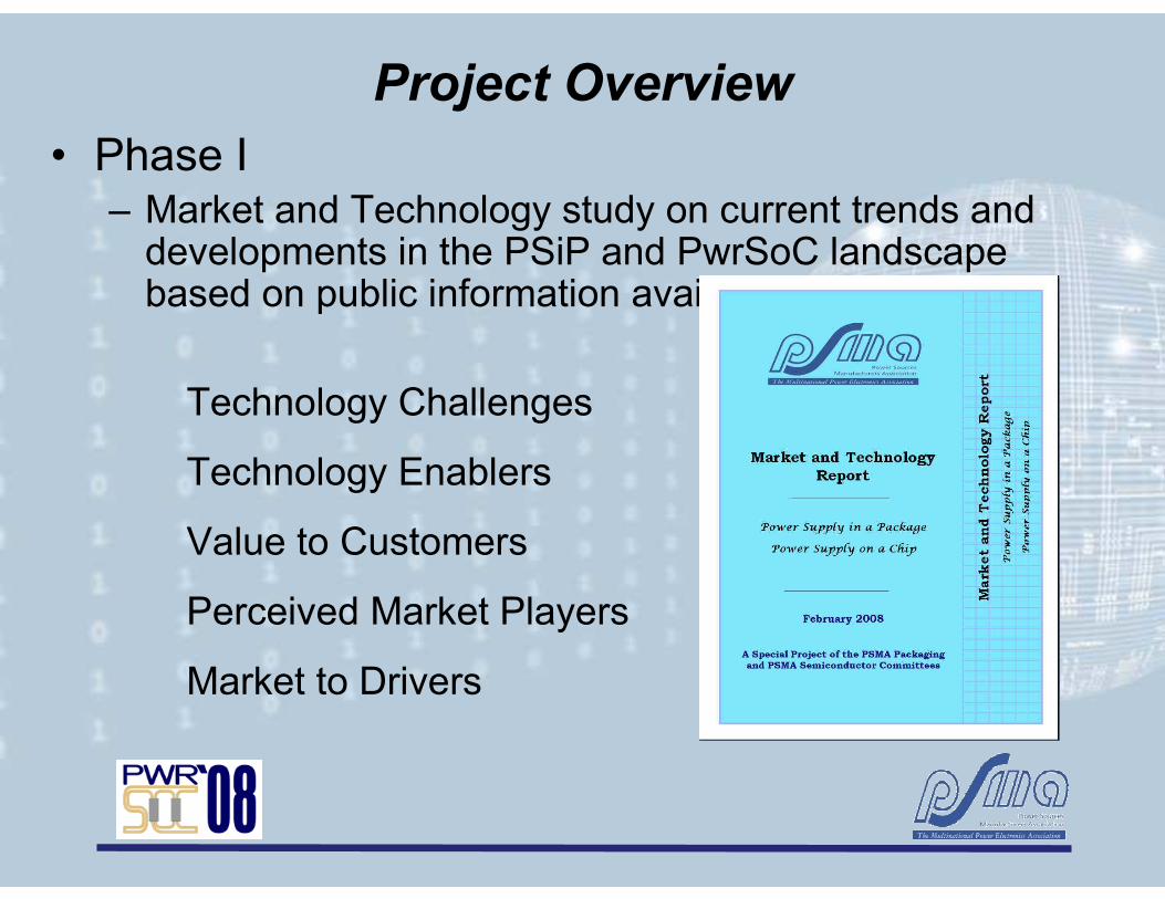
Project Overview
• Phase I– Market and Technology study on current trends and developments in the PSiP and PwrSoC landscape based on public information available.
Technology Challenges
Technology Enablers
Value to Customers
Perceived Market Players
Market to Drivers

PSiP Product
Lineage Power APTS/APXS006A0X:
Linear Technology
LTM 4600 Series
Delta NE 12S0A0V10PMFA
Bel Power Arrowhead Series
Vishay SiFX1300

PwrSoC Product
Enpirion, Inc.
This 26-pin IC packaged in a DFN contains a
totally integrated dc-dc converter with FETs,
controller, and an inductor. It occupies 135
mm2 pc board space.Fuji Electric Device Technology
Company
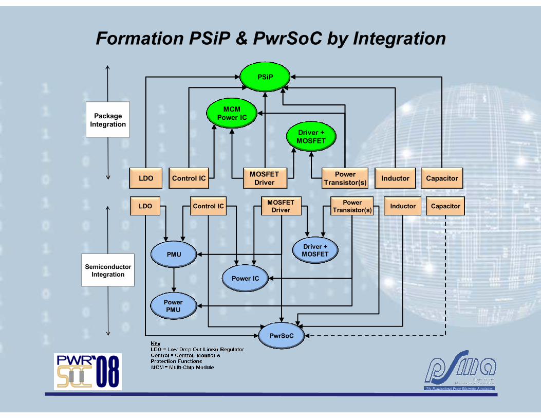
Formation PSiP & PwrSoC by Integration
Power
Transistor(s)
Driver +
MOSFET
MCM
Power IC
PSiP
Package
Integration
LDO Control ICMOSFET
DriverInductor Capacitor
Power
Transistor(s)LDO Control IC
MOSFET
DriverInductor Capacitor
Driver +
MOSFET
Power
PMU
PMU
Power IC
PwrSoC
Semiconductor
Integration

Historic Packaged Integration Roadmap
1990 20001980 2006
Experimental
Commercial Product
Relative Level of Density
(Functions/m
m3)
Ignition
Systems
CPES
Modules
Siemens
TempFET®
PSiP
Multi-chip
Power ICs
Pico
Type
Supplies
Bricks

Historic Semiconductor Integration Roadmap
1990 20001980 2006
Experimental
Commercial Product
Relative Level of Integration
MotorolaHigh Side
Switch
Toshiba
Motor Drive
Chip
IR
SmartFET®
Power
PMU
Multiple
Switcher
PMU
High Side
Switch
HV Motor
Drive IC
Single
Switcher
PMU
PwrSoC
Siemens
TempFET®
LV Motor Drive
Power IC

Voltage Ranges
• PSiP (12 Vin version)– Vin Range: 4 V to 28 V
– Majority Vin Range: 4.5 V to 18 V
– Vout Range: 0.6 V to 5.5 V
• PSiP (5 Vin version)– Vin Range: 2.2 V to 6 V
– Majority Vin Range: 3 V to 5.5 V
– Vout Range: 0.8 V to 5 V
– Majority Vout Range: 1 V to 4 V
• PwrSoC (5 Vin only)– Vin Range: 2.2 V to 5.5 V
– Vout Range: 0.8 V to 3.3 V
PwrSoC Input Voltage Range
0 0.5 1 1.5 2 2.5 3 3.5 4 4.5 5 5.5 6
EN5366
FB6831J
Vin (Volts)
(IBS = 5 Vin Product)
PwrSoC Output Voltage Range
0 0.5 1 1.5 2 2.5 3 3.5 4 4.5 5 5.5 6
EN5366
FB6831J
Vout (Volts)
(IBS = 5 Vin Product)
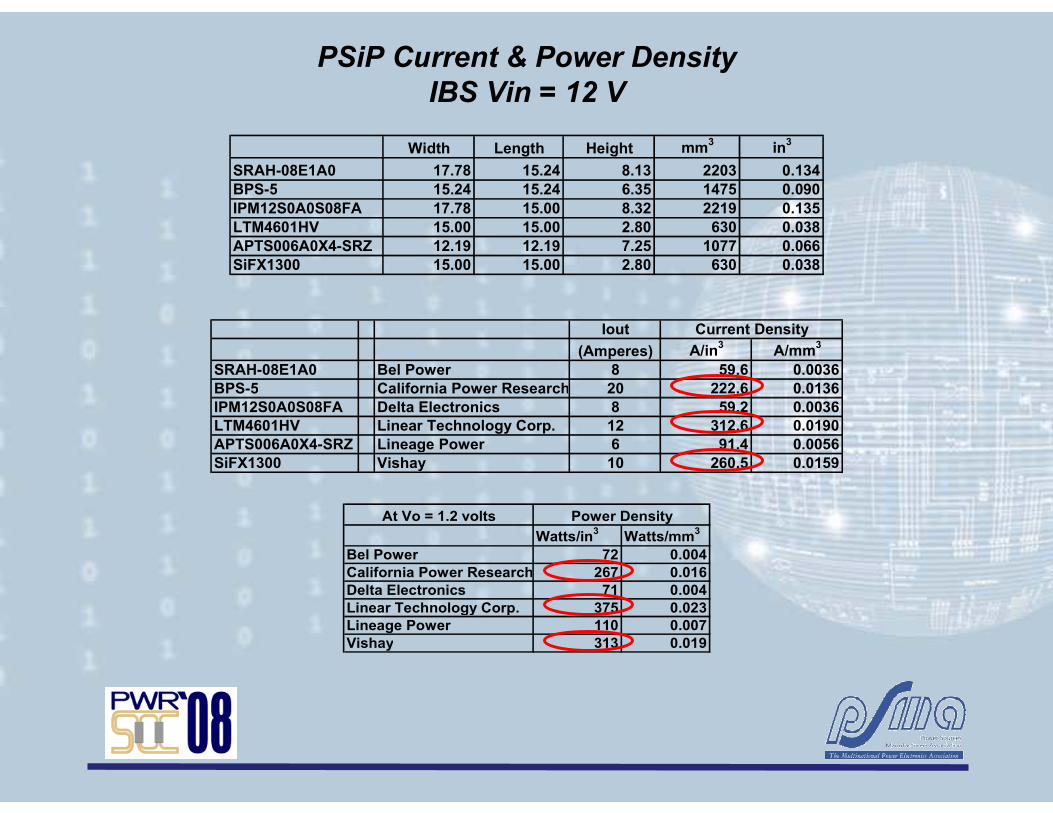
PSiP Current & Power Density
IBS Vin = 12 V
Width Length Height mm3
in3
SRAH-08E1A0 17.78 15.24 8.13 2203 0.134
BPS-5 15.24 15.24 6.35 1475 0.090
IPM12S0A0S08FA 17.78 15.00 8.32 2219 0.135
LTM4601HV 15.00 15.00 2.80 630 0.038
APTS006A0X4-SRZ 12.19 12.19 7.25 1077 0.066
SiFX1300 15.00 15.00 2.80 630 0.038
Iout
(Amperes) A/in3
A/mm3
SRAH-08E1A0 Bel Power 8 59.6 0.0036
BPS-5 California Power Research 20 222.6 0.0136
IPM12S0A0S08FA Delta Electronics 8 59.2 0.0036
LTM4601HV Linear Technology Corp. 12 312.6 0.0190
APTS006A0X4-SRZ Lineage Power 6 91.4 0.0056
SiFX1300 Vishay 10 260.5 0.0159
Current Density
At Vo = 1.2 volts
Watts/in3
Watts/mm3
Bel Power 72 0.004
California Power Research 267 0.016
Delta Electronics 71 0.004
Linear Technology Corp. 375 0.023
Lineage Power 110 0.007
Vishay 313 0.019
Power Density

Iout
(Amperes) A/in3
A/mm3
SRAH-12Fxx0 Bel Power 12 89.4 0.005
IPM04S0A0S10FA Delta Electronics 10 78.7 0.005
LTM4608 Linear Technology Corp. 8 347.3 0.021
MIC38300 Micrel 2.2 1769.9 0.108
MPD6S012S muRata 3 12.4 0.001
FX5455G10 Vishay 4 114.4 0.007
Current Density
PSiP Current & Power Density
IBS = 5 V
Width Length Height mm3
in3
SRAH-12Fxx0 17.78 15.24 8.13 2203 0.134
IPM04S0A0S10FA 17.78 15.00 7.82 2086 0.127
LTM4608 9.00 15.00 2.80 378 0.023
MIC38300 4.00 6.00 0.85 20 0.001
MPD6S012S 21.00 9.00 21.00 3969 0.242
FX5455G10 12.20 14.70 3.20 574 0.035
At Vo = 1.2 volts
Watts/in3
Watts/mm3
Bel Power 107 0.007
Delta Electronics 94 0.006
Linear Technology Corp. 417 0.025
Micrel 5841 0.356
muRata 15 0.001
Vishay 137 0.008
Power Density

PwrSoC Current and Power Density
IBS = 5 V
0
1
2
3
4
5
6
7
EN5366
FB6831J
Amperes (A)
Product
PwrSoC Output Current Rating
(IBS = 5 Vin Product)
0
200
400
600
800
1000
1200
1400
EN5366
FB6831J
Current Density (A/in3)
Product
PwrSoC Current Density Rating
(IBS = 5 Vin Product)
0.000
0.010
0.020
0.030
0.040
0.050
0.060
0.070
0.080
EN5366
FB6831J
Current Density (A/m
m3)
Product
PwrSoC Current Density Rating
(IBS = 5 Vin Product)
Width Length Height
mm mm mm mm3
in3
EN5366 Enpirion 10.00 12.00 1.85 222.0 0.0135
FB6831J Fuji 2.40 2.95 1.00 7.1 0.0004
Volume
Iout
Amperes A/in3
A/mm3
EN5366 Enpirion 6 444 0.027
FB6831J Fuji 0.5 1159 0.071
Current Density
Watts/in3
Watts/mm3
EN5366 Enpirion 532 0.032
FB6831J Fuji 1391 0.085
Power DensityAt Vo = 1.2 volts

PSiP2PwrSoC Phase I Trends – Current
Density vs. Frequency
0
200
400
600
800
1000
1200
1400
1600
1800
2000
0 200 400 600 800 1000 1200 1400 1600 1800 2000
Current Density (A/in2)
Frequency (kHz)
PSiP, IBS = 12 V
PSiP, IBS = 5 V

PSiP & PwrSoC
Switching Frequency
0
1000
2000
3000
4000
5000
6000
2000 2002 2004 2006 2008 2010
Frequency (kHz)
Year Introduced
PSiP, IBS = 12 V
PSiP, IBS = 5 V
PwrSoC
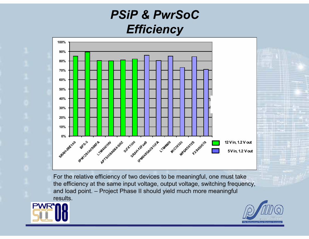
PSiP & PwrSoC
Efficiency
For the relative efficiency of two devices to be meaningful, one must take the efficiency at the same input voltage, output voltage, switching frequency, and load point. – Project Phase II should yield much more meaningful results.
0%
10%
20%
30%
40%
50%
60%
70%
80%
90%
100%
APTS006A0X4-SRZ
SRAH-12Fxx0
12 V in, 1.2 V out
5 V in, 1.2 V out
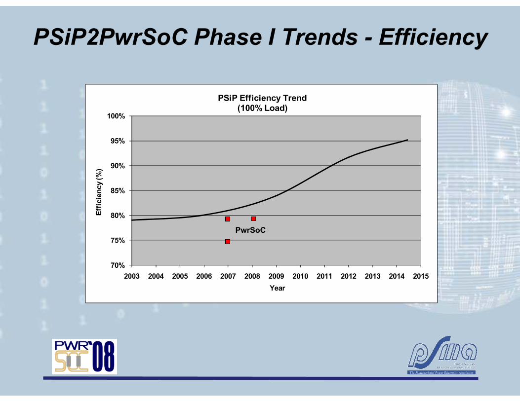
PSiP2PwrSoC Phase I Trends - Efficiency
70%
75%
80%
85%
90%
95%
100%
2003 2004 2005 2006 2007 2008 2009 2010 2011 2012 2013 2014 2015
Efficiency (%)
Year
PSiP Efficiency Trend(100% Load)
PwrSoC
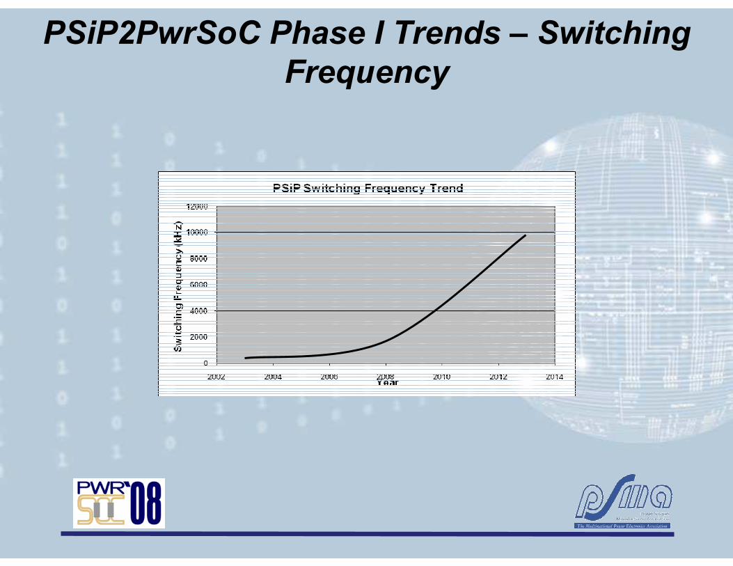
PSiP2PwrSoC Phase I Trends – Switching
Frequency

PSiP2PwrSoC Phase I Trends – Current Density

PwrSoC
Integrated Inductor Technology
Integrated MEMS inductor Technology, Source Enpirion
Traditional Inductor Technology
Air Core Inductor Technology
for RF Circuits

Potential PwrSoC Integrated Capacitor Technologies
Classic DRAM Circuit – Source NXP
Trench Capacitor with Atomic Layer Deposition (ALD)
Classic DRAM Circuit – Source NXP
Source NXP

PSiP Technology Influence Map
Technology Influence Map Application Enabling Map
= Barrier
High Current
LED Modules Packaging
High
Density
Inductor
Power IC
(Control +
DrMOS
Control IC
Technology
Close
Proximity
PSiP
Chip Scale Packages
Basic
Inductor
PSiP
Silicon
Advanced Magnetic
Materials
Power
MOSFET
MOSFET
Driver
Vertical
DMOS
Lateral
DMOS
Miniature
Embedded
Supplies
VRD or
Embedded VRM
uP or ASIC higher
dynamics
Portables,
Handheld Devices
Entertainment
Graphics
High
Performance
Servers
HD Interconnect
Adv. Thermal Designs Center Pad
Construction
Center LGA Construction
Faster Time-to-Market
Faster
Design-in
Primary
Application
Performance
Drivers
Power Supply Engineering Shortage
Drop-in
Designs
Higher Efficiency
Systems
High Pin-
Count IC
Packages
Low Noise
Regulators
Lower IC
Voltage
Increased
Number of
Voltage
Customization
Programmable
Voltages
Sources
Digital
Control
Analog
Control
RF Packaging
Technology
Data Center
Inefficiencies
High Density
Capacitor
RF
Technology
RF Technology
Peel back map a little at a time
The Map will be developed more fully as the result of the PSMA Phase II work.
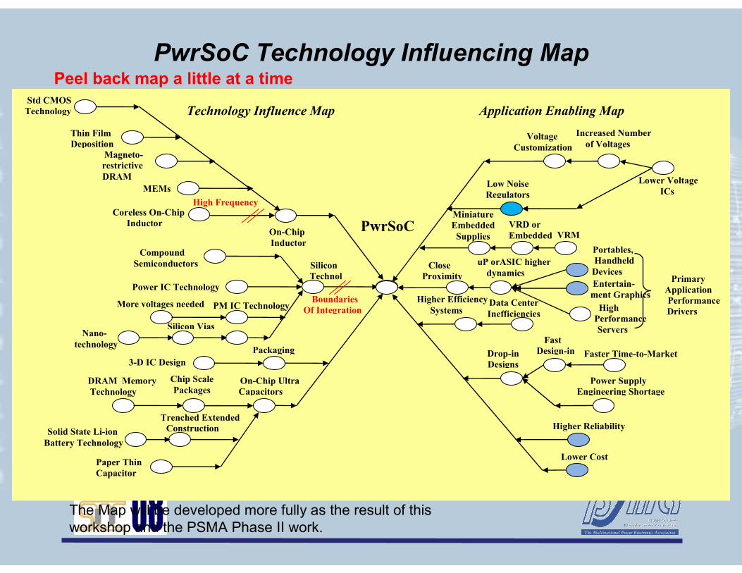
PwrSoC Technology Influencing Map
Technology Influence Map
Chip Scale
Packages DRAM Memory
Technology
On-Chip Ultra
Capacitors
Packaging
Silicon
Technol
On-Chip
Inductor
PwrSoC Coreless On-Chip
Inductor
Technology
High Frequency
Boundaries
Of Integration
3-D IC Design
Silicon Vias
MEMs
Power IC Technology
Compound
Semiconductors
PM IC Technology
Nano-
technology
Trenched Extended
Construction
More voltages needed
Solid State Li-ion
Battery Technology
Magneto-
restrictive
DRAM
Thin Film
Deposition
Std CMOS
Technology
Paper Thin
Capacitor
Technology
Close
Proximity
Miniature
Embedded
Supplies
VRD or
Embedded VRM
uP orASIC higher
dynamics
Portables,
Handheld
Devices
Entertain-
ment Graphics
High
Performance
Servers
Faster Time-to-Market
Fast
Design-in
Primary
Application
Performance
Drivers
Power Supply
Engineering Shortage
Drop-in
Designs
Higher Efficiency
Systems
Low Noise
Regulators
Lower Voltage
ICs
Increased Number
of Voltages Voltage
Customization
Data Center
Inefficiencies
Lower Cost
Higher Reliability
Application Enabling Map
The Map will be developed more fully as the result of this workshop and the PSMA Phase II work.
Peel back map a little at a time

Recent Events
• Product introduction rate quieted down over the past 6 months– Some suppliers are filling in some lower current offering– We expect introductions to increase significantly in the
next 18 months. We are in the “eye of the design”– One company has withdrawn from the PwrSoC market.– They feel they targeted the wrong market in the 300 ma to
600 ma range in 6 offerings and that the real market is much higher current
– They overestimated the acceptable market price.
• Hitachi has developed PSiP that includes input capacitor – claims 3% improvement in efficiency
•

Comparing PSiP and PwrSoC
• PwrSoC density is 48% higher than PSiP product
• PwrSoC’s and PSiP’s serve similar markets
• PwrSoC is definitely a lower current device than PSiP, yet we see PSiP products rated at below 1 ampere.
• Functionality is identical – one dc-dc synchronous buck converter.
• Surface mount packages dominate both products
• The first indication of price comparison between PSiP and PwrSoC devices show that it is too early to make an accurate comparison– We feel that an accurate perception is that PwrSoC will have a
lower cost than PSiP.

Role of PSiP and PwrSoC
• We see them sharing the power spectrum with the POL
• PwrSoC is at 9 A and expect to go higher
• PSiP is at 12 A and is expected to go beyond 20 A within 24 months
• Low end of PSiP is reaching deep into the PwrSoC lower range to well below 1 V but we expect them to retrench to the higher currents as soon as cost reduction is realized by the PwrSoC devices
• The embedded solution will remain a mainstream solution with PwrSoC and PSiP taking market share at an aggressive rate
PwrSoC PSiP POLIout
Current Range(Amperes)
0.3 7 12 90 150
Embedded Power IC & Discrete
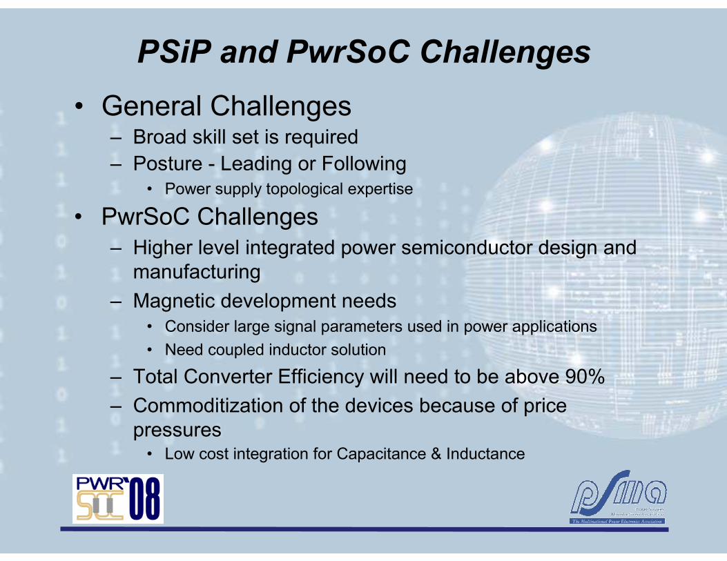
PSiP and PwrSoC Challenges
• General Challenges– Broad skill set is required– Posture - Leading or Following
• Power supply topological expertise
• PwrSoC Challenges– Higher level integrated power semiconductor design and
manufacturing
– Magnetic development needs• Consider large signal parameters used in power applications
• Need coupled inductor solution
– Total Converter Efficiency will need to be above 90%
– Commoditization of the devices because of price pressures• Low cost integration for Capacitance & Inductance

PSiP2PwrSoC Phase II
• Focus on understanding integration, packaging and technology trends based on a benchmark study of selected commercial products in the PSIP &PwrSoC space.
• The review is not intended to reveal proprietary design information. – Individual products will not be identified in the project, in interim or
final reports or presentations or in any publicity material related to the project
• Phase II report to be published 1Q09 Technology Challenges
• Project sponsorship opportunities are still available to interested parties.
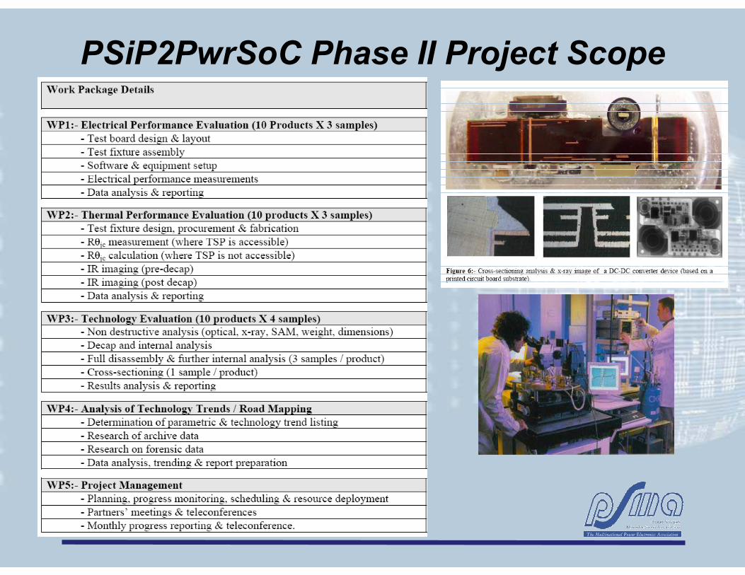
PSiP2PwrSoC Phase II Project Scope

Acknowledgements• Phase I PSMA Steering Committee
– Cian Ó Mathúna, Tyndall National Institute, Ireland
– Brian Narveson, Texas Instruments
– Alex Craig, Fairchild Semiconductor
– Doug Hopkins, SUNY, Buffalo
– Joe Horzepa, PSMA
– John Shen, University of Central Florida
• Phase I Contractor– Anagenesis, Inc.- Arnold Alderman
- Vicky Panossian
• Phase II Contractor– Tyndall National Institute – - Mr. Finbarr Waldron
- Dr. Ningning Wang- Mr. Kenneth Rodgers (Tyndall)
– Power Electronics Research Laboratory (PERL) at University College Cork, Ireland. - Dr. Raymond Foley- Mr. James Griffiths - Dr. Michael Egan
– Anagenesis, Inc. - Arnold Alderman- Vicky Panossian
Thank YouThank You
to the to the
PwrSoC 08 Sponsors, PwrSoC 08 Sponsors,
Organizers & AttendeesOrganizers & Attendees


