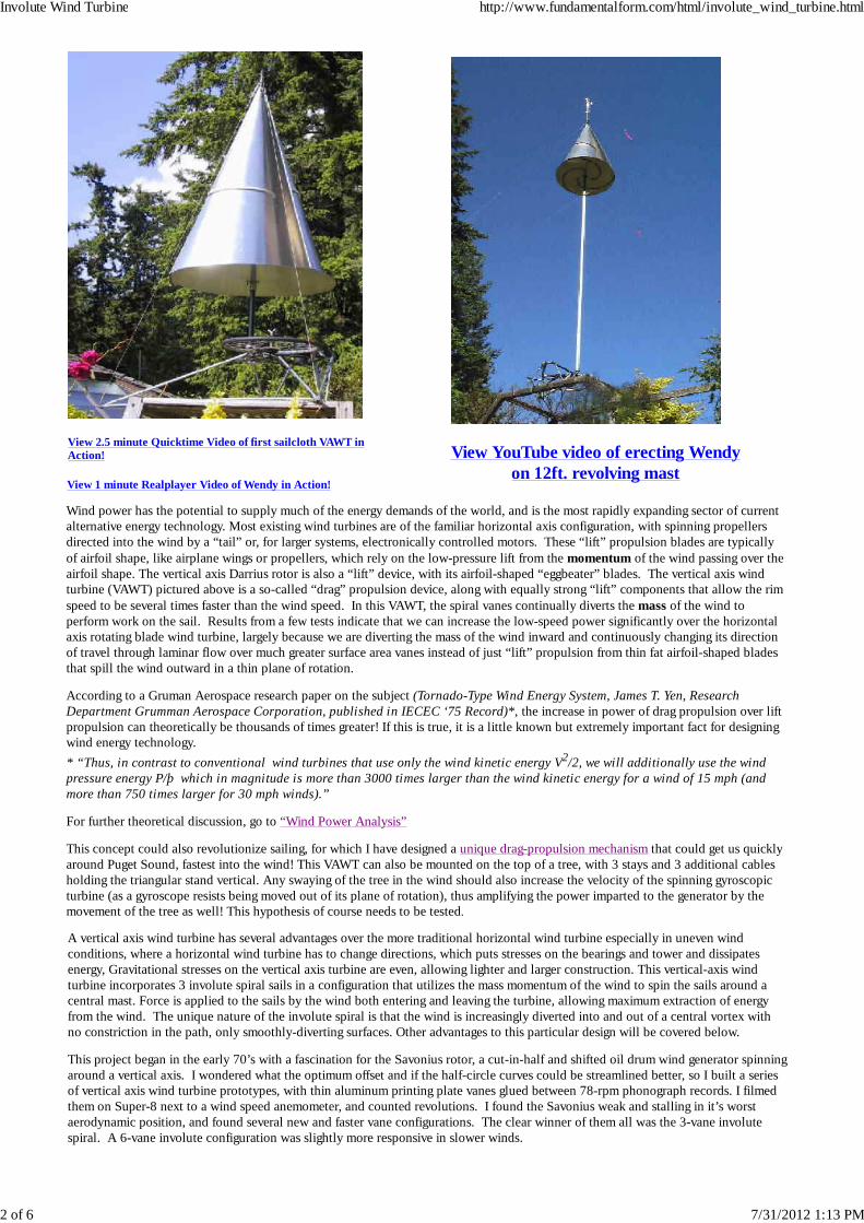
[ Home] [ Other Creations] [ Architecture] [ Fundamental Form] [ Energy Breakthroughs] [ Energy from Waste] [ Biomass Gasifier Breakthrough] [ Wind Power Analysis] [Involute Wind Turbine] [ Radical Wind-Turbine Boat] [ Water Energy] [ high- pressure fan] [ Writings] [ Contact] [ PLANS] [ Opportunities] REVOLUTIONARY NEW DESIGN! VERTICAL AXIS INVOLUTE SPIRAL WIND TURBINE VIEW VIDEO OF STREAMLINED FINNED TURBINE This more aerodynamic configuration, with 20ft tall revolving mast, weighs 21lb, with 6.5lb lb mast, + bearing, cables and tensegrity wires = 30lb total. The heavier generator & gearbox will be down below, where they are easy to work on. An anemometer on top and stiff telltales at vane openings will show wind movement as vanes turn into and out of wind. This drawing was first built with sailcloth vanes (right), which was very promising, but proved too flexible for optimum performance. The 3-vaned aluminum model shown below, named “Wendy the Windturbine”, was then built. It is a great improvement, producing significant power for it’s small size in a moderate breeze. To elevate Wendy into less turbulent wind a 12ft revolving extension tube was added, held rigid by another set of 3 guy cables from the base of the turbine (center picture). The entire rig --- turbine, mast, extension-tube, bearings, guy-cables weighs about 40lb and works very well. With a better bottom thrust bearing, this extension technique could be duplicated to raise the turbine much higher into stronger winds. Involute Wind Turbine http://www.fundamentalform.com/html/involute_wind_turbine.html 1 of 6 7/31/2012 1:13 PM
REVOLUTIONARY NEW DESIGN!VERTICAL AXIS INVOLUTE SPIRAL WIND TURBINE
VIEW VIDEO OF STREAMLINED FINNED TURBINE
This more aerodynamic configuration, with 20ft tall revolving mast, weighs 21lb, with6.5lb lb mast, + bearing, cables and tensegrity wires = 30lb total. The heavier generator& gearbox will be down below, where they are easy to work on. An anemometer on topand stiff telltales at vane openings will show wind movement as vanes turn into and out ofwind.
This drawing was first built withsailcloth vanes (right), which wasvery promising, but proved tooflexible for optimum performance.
The 3-vaned aluminum modelshown below, named “Wendy theWindturbine”, was then built. It isa great improvement, producingsignificant power for it’s small sizein a moderate breeze. To elevateWendy into less turbulent wind a12ft revolving extension tube wasadded, held rigid by another set of3 guy cables from the base of theturbine (center picture). Theentire rig --- turbine, mast,extension-tube, bearings,guy-cables weighs about 40lb andworks very well. With a betterbottom thrust bearing, thisextension technique could beduplicated to raise the turbinemuch higher into stronger winds.
View 2.5 minute Quicktime Video of first sailcloth VAWT inAction!
View 1 minute Realplayer Video of Wendy in Action!
View YouTube video of erecting Wendyon 12ft. revolving mast
Wind power has the potential to supply much of the energy demands of the world, and is the most rapidly expanding sector of currentalternative energy technology. Most existing wind turbines are of the familiar horizontal axis configuration, with spinning propellersdirected into the wind by a “tail” or, for larger systems, electronically controlled motors. These “lift” propulsion blades are typicallyof airfoil shape, like airplane wings or propellers, which rely on the low-pressure lift from the momentum of the wind passing over theairfoil shape. The vertical axis Darrius rotor is also a “lift” device, with its airfoil-shaped “eggbeater” blades. The vertical axis windturbine (VAWT) pictured above is a so-called “drag” propulsion device, along with equally strong “lift” components that allow the rimspeed to be several times faster than the wind speed. In this VAWT, the spiral vanes continually diverts the mass of the wind toperform work on the sail. Results from a few tests indicate that we can increase the low-speed power significantly over the horizontalaxis rotating blade wind turbine, largely because we are diverting the mass of the wind inward and continuously changing its directionof travel through laminar flow over much greater surface area vanes instead of just “lift” propulsion from thin fat airfoil-shaped bladesthat spill the wind outward in a thin plane of rotation.
According to a Gruman Aerospace research paper on the subject (Tornado-Type Wind Energy System, James T. Yen, ResearchDepartment Grumman Aerospace Corporation, published in IECEC ‘75 Record)*, the increase in power of drag propulsion over liftpropulsion can theoretically be thousands of times greater! If this is true, it is a little known but extremely important fact for designingwind energy technology.
* “Thus, in contrast to conventional wind turbines that use only the wind kinetic energy V2/2, we will additionally use the windpressure energy P/þ which in magnitude is more than 3000 times larger than the wind kinetic energy for a wind of 15 mph (andmore than 750 times larger for 30 mph winds).”
For further theoretical discussion, go to “Wind Power Analysis”
This concept could also revolutionize sailing, for which I have designed a unique drag-propulsion mechanism that could get us quicklyaround Puget Sound, fastest into the wind! This VAWT can also be mounted on the top of a tree, with 3 stays and 3 additional cablesholding the triangular stand vertical. Any swaying of the tree in the wind should also increase the velocity of the spinning gyroscopicturbine (as a gyroscope resists being moved out of its plane of rotation), thus amplifying the power imparted to the generator by themovement of the tree as well! This hypothesis of course needs to be tested.
A vertical axis wind turbine has several advantages over the more traditional horizontal wind turbine especially in uneven windconditions, where a horizontal wind turbine has to change directions, which puts stresses on the bearings and tower and dissipatesenergy, Gravitational stresses on the vertical axis turbine are even, allowing lighter and larger construction. This vertical-axis windturbine incorporates 3 involute spiral sails in a configuration that utilizes the mass momentum of the wind to spin the sails around acentral mast. Force is applied to the sails by the wind both entering and leaving the turbine, allowing maximum extraction of energyfrom the wind. The unique nature of the involute spiral is that the wind is increasingly diverted into and out of a central vortex withno constriction in the path, only smoothly-diverting surfaces. Other advantages to this particular design will be covered below.
This project began in the early 70’s with a fascination for the Savonius rotor, a cut-in-half and shifted oil drum wind generator spinningaround a vertical axis. I wondered what the optimum offset and if the half-circle curves could be streamlined better, so I built a seriesof vertical axis wind turbine prototypes, with thin aluminum printing plate vanes glued between 78-rpm phonograph records. I filmedthem on Super-8 next to a wind speed anemometer, and counted revolutions. I found the Savonius weak and stalling in it’s worstaerodynamic position, and found several new and faster vane configurations. The clear winner of them all was the 3-vane involutespiral. A 6-vane involute configuration was slightly more responsive in slower winds.
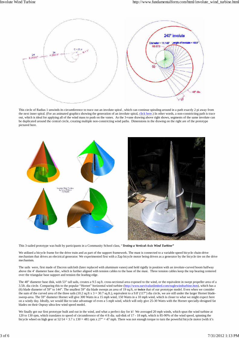
This circle of Radius 1 unwinds its circumference to trace out an involute spiral , which can continue spiraling around in a path exactly 2 pi away fromthe next inner spiral. (For an animated graphics showing the generation of an involute spiral, click here.) In other words, a non-constricting path is traceout, which is ideal for applying all of the wind mass to push on the vanes. As the 3-vane drawing above right shows, segments of the same involute canbe duplicated around the central circle, creating multiple non-constricting wind paths. Dimensions in the drawing on the right are of the prototypepictured here.
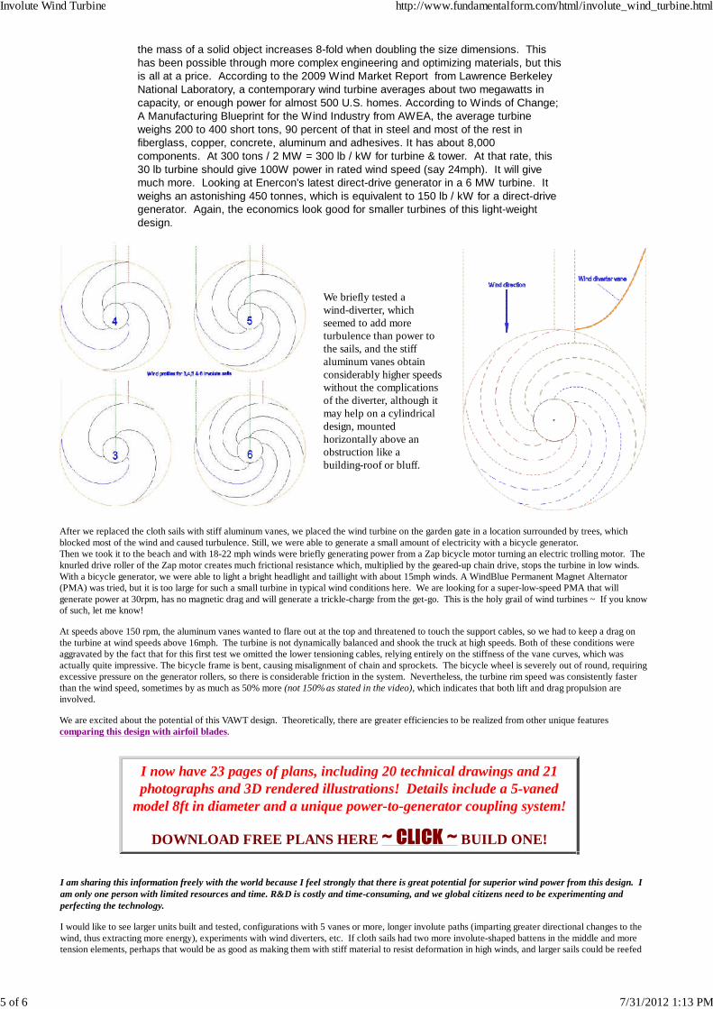
This 3-sailed prototype was built by participants in a Community School class, “Testing a Vertical-Axis Wind Turbine”
We utilized a bicycle frame for the drive train and as part of the support framework. The mast is connected to a variable-speed bicycle chain-drivemechanism that drives an electrical generator. We experimented first with a Zap bicycle motor being driven as a generator by the bicycle tire on the drivemechanism.
The sails were, first made of Dacron sailcloth (later replaced with aluminum vanes) and held rigidly in position with an involute-curved boom halfwayabove the 4’ diameter base disc, which is further aligned with tension cables to the base of the mast. Three tension cables keep the top bearing centeredover the triangular base support and tension the leading edge.
The 48” diameter base disk, with 53” tall sails, creates a 9.5 sq.ft. cross-sectional area exposed to the wind, or the equivalent in swept propeller area of a3.5ft. dia circle. Comparing this to the popular “Hornet” horizontal wind turbine (http://www.survivalunlimited.com/eaglewindturbine.htm), which has a(6) blade diameter of 59” to 144”. The smallest 59” dia blade sweeps an area of 19 sq.ft, or twice that of our prototype model. Even when we considerthe sum of the curved area of the three sails (10.2 sq.ft x 3 = 30.7 sq.ft.), equivalent to a 9.8' (117") dia circle, we are still under the larger Hornet blade-sweep-area. The 59” diameter Hornet will give 300 Watts in a 15 mph wind, 150 Watts in a 10 mph wind, which is closer to what we might expect hereon a windy day. Ideally, we would like to take advantage of even a 5 mph wind, which will only give 25-30 Watts with the Hornet specially-designed fatblades on their Ospray ultra-low wind speed model.
We finally got our first prototype built and out in the wind, and what a perfect day for it! We averaged 20 mph winds, which spun the wind turbine at120 to 130 rpm, which translates to speed of circumference of the 4 ft dia. sail-disk of 17 - 18 mph, which is 85-90% of the wind speed, spinning thebicycle wheel on high gear at 52/14 = 3.7 x 130 = 481 rpm x 27” = 47 mph. There was not enough torque to turn the powerful bicycle motor (with it’s
1.25” roller and much magnetic and frictional resistance at that speed ~ when we geared down it could almost balance the friction of the motor, but wedidn’t generate much power. Those of us taking part in the test (Larry, Blaine, Bill & Ebey) nevertheless considered it a successful test and excitingbeginning, for the following reasons:
Significant power was generated despite the flapping sails and severe imbalances. The cloth sails were too loose for the high winds, and the leading edge bowed inand out 3 or 4 inches as it spun, adding vibration & slowing it down considerably. The sails luffed badly on the upwind side, caving in and rippling the surfacecoming into the wind. This seemed to be the most severe dampening to the smoothspinning of the sails and their aerodynamic properties.The sails/disk/booms were quite imbalanced, especially as we tightened the tensionlines, which shook the truck it was mounted on, dissipating considerable powerand prevented higher speeds.We replaced the cloth sails with stiff aluminum sheets that keep their smoothprofile throughout their spin and are easier to tune the tension members andbalance the rig.
Another observation from our truck-roof mounting platform. While getting theturbine up in position certainly wasn’t a breeze in this 20 mph wind, once it was upand spinning, we were able to unstrap it and stand there talking for a while withouthaving to hold it down. Very little energy was offered in resistance by the turbinevanes, and the gyroscopic stabilization got us talking about how easy it would beto mount it on top of a tree, using the existing framework with 3 cables down tobolts in the tree 6 feet down. How much energy could we capture from the treeswaying?
What about adding more sails? Remember, this turbine achieves much of itspower from the impact of air molecules on the continuously-inward-spiralingturbine vanes. If we have 3 more vanes, we have doubled the molecular impactsfrom the air, and because the geometry of the passageways between the sails isnon-constricting, all impacts are moving the vane around the mast. This
proposition has been challenged by sailors and wind turbine experts alike...... only testing will tell..... What about making one with a clear lower disk, sowe can watch ribbons, photograph meter readouts, meditate on the expanding spirals?
Frequently Asked Questions:Q: why the “conical” design instead of a “cylindrical” configuration of greater wind shadow and surface area?I and others have experimented with cylindrical profiles. While the cylindrical cross section has greater surface area, thereare several advantages to the conical shape.
Engineering-wise, it is easier to build stiffer and lighter with tension/compression balance.The lightest, sturdiest support mechanism is with a bearing at the top held in place by guy cables. The conical sailconfiguration is ideally suited to this support method, whereas an extended support framework must be built on top ofthe upper disk to allow support cables to be oriented downward at the best support angle without touching the turbine.When you eliminate the top disk, you can build a larger conical turbine, with greater wind shadow than a cylindrical one ofthe same amount of material.Because the wind traveling through the conical design flows through a double involute path of varied length, there shouldbe an optimum region of the cone that is “tuned to the wind”, creating max power from a spectrum of wind speeds, so thisconfiguration may have aerodynamic advantages too.
We have hot been able to accurately determine the relative efficiencies of conical vs cylindrical design. Extensive wind tunneltesting is essential to optimize this technology.
What about combining the slow_speed vawt with an airfoil blade to get it turning in lighter winds?
The large vanes in involute spiral configuration create the most rotational thrust with the least turbulence at 1/3 to 1/6th thetip speed of a thin airfoil blade. I don’t believe the two technologies can be successfully integrated. The balance of highpressure thrust on the concave side of the curved vane with low pressure lift on the other side of the vane is a smoothlytransitioning phenomenon, which would be radically altered by any attempt to change the shape to create more lift at anyparticular location on the vanes. How many vanes of what size involute in what wind conditions are optimum?This and other important questions need to be determined in wind-tunnel experiments. Want to help? Although it would behighly interesting to employ flow-analysis software to predict performance and optimization of variables, I don’t trustcomputer simulations to give an accurate prediction of performance with respect to these variables, especially considering theunknown interactions happening in the center of the turbine (~ I suspect traveling vortex streets connecting intake & outlet ~)and with entrained air around the periphery. Counterweighted flow flaps have been mounted onto the leading edge of theturbine vanes and show a precise moment of switching from air entering to air exiting the channel as the turbine turns.
Size considerations:
Large commercial turbines get bigger and bigger, despite the “elephant” syndrome that
the mass of a solid object increases 8-fold when doubling the size dimensions. Thishas been possible through more complex engineering and optimizing materials, but thisis all at a price. According to the 2009 Wind Market Report from Lawrence BerkeleyNational Laboratory, a contemporary wind turbine averages about two megawatts incapacity, or enough power for almost 500 U.S. homes. According to Winds of Change;A Manufacturing Blueprint for the Wind Industry from AWEA, the average turbineweighs 200 to 400 short tons, 90 percent of that in steel and most of the rest infiberglass, copper, concrete, aluminum and adhesives. It has about 8,000components. At 300 tons / 2 MW = 300 lb / kW for turbine & tower. At that rate, this30 lb turbine should give 100W power in rated wind speed (say 24mph). It will givemuch more. Looking at Enercon's latest direct-drive generator in a 6 MW turbine. Itweighs an astonishing 450 tonnes, which is equivalent to 150 lb / kW for a direct-drivegenerator. Again, the economics look good for smaller turbines of this light-weightdesign.
We briefly tested awind-diverter, whichseemed to add moreturbulence than power tothe sails, and the stiffaluminum vanes obtainconsiderably higher speedswithout the complicationsof the diverter, although itmay help on a cylindricaldesign, mountedhorizontally above anobstruction like abuilding-roof or bluff.
After we replaced the cloth sails with stiff aluminum vanes, we placed the wind turbine on the garden gate in a location surrounded by trees, whichblocked most of the wind and caused turbulence. Still, we were able to generate a small amount of electricity with a bicycle generator.Then we took it to the beach and with 18-22 mph winds were briefly generating power from a Zap bicycle motor turning an electric trolling motor. Theknurled drive roller of the Zap motor creates much frictional resistance which, multiplied by the geared-up chain drive, stops the turbine in low winds.With a bicycle generator, we were able to light a bright headlight and taillight with about 15mph winds. A WindBlue Permanent Magnet Alternator(PMA) was tried, but it is too large for such a small turbine in typical wind conditions here. We are looking for a super-low-speed PMA that willgenerate power at 30rpm, has no magnetic drag and will generate a trickle-charge from the get-go. This is the holy grail of wind turbines ~ If you knowof such, let me know!
At speeds above 150 rpm, the aluminum vanes wanted to flare out at the top and threatened to touch the support cables, so we had to keep a drag onthe turbine at wind speeds above 16mph. The turbine is not dynamically balanced and shook the truck at high speeds. Both of these conditions wereaggravated by the fact that for this first test we omitted the lower tensioning cables, relying entirely on the stiffness of the vane curves, which wasactually quite impressive. The bicycle frame is bent, causing misalignment of chain and sprockets. The bicycle wheel is severely out of round, requiringexcessive pressure on the generator rollers, so there is considerable friction in the system. Nevertheless, the turbine rim speed was consistently fasterthan the wind speed, sometimes by as much as 50% more (not 150% as stated in the video), which indicates that both lift and drag propulsion areinvolved.
We are excited about the potential of this VAWT design. Theoretically, there are greater efficiencies to be realized from other unique featurescomparing this design with airfoil blades.
I now have 23 pages of plans, including 20 technical drawings and 21photographs and 3D rendered illustrations! Details include a 5-vaned
model 8ft in diameter and a unique power-to-generator coupling system!
DOWNLOAD FREE PLANS HERE ~ CLICK ~ BUILD ONE!
I am sharing this information freely with the world because I feel strongly that there is great potential for superior wind power from this design. Iam only one person with limited resources and time. R&D is costly and time-consuming, and we global citizens need to be experimenting andperfecting the technology.
I would like to see larger units built and tested, configurations with 5 vanes or more, longer involute paths (imparting greater directional changes to thewind, thus extracting more energy), experiments with wind diverters, etc. If cloth sails had two more involute-shaped battens in the middle and moretension elements, perhaps that would be as good as making them with stiff material to resist deformation in high winds, and larger sails could be reefed
We need funding to test the turbine mounted on a boat driving a screw propeller or preferably a drag-propulsion paddle mechanism of my revolutionarydesign, to do wind tunnel experiments, to build larger units with direct-drive generator, and to test upside down as a tidal-power generator. This willproduce much more power and test the hydrodynamics of the shape.
I have lots of ideas and suggestions. All I ask is that you inform me of your development work and let me offer suggestions and coordinate efforts andinformation so that all will benefit.
I am available as a consultant.
Email or write to:
Larry Dobson7118 Fiske RdClinton, WA [email protected] call 360-579-1763
BIO:
Larry Dobson is an energy consultant and has studied and experimented with new approaches and concepts in Alternative Energy Applications, notably,high temperature biomass combustion, heat-exchanger design, biogas systems, solar collector and heat storage technology, wind turbine design, human-powered vehicles, power linkages and superior articulated stilt designs. He is skilled in realistic 3D Solidmodeling (Computer-Aided-Design), steel andaluminum structural design, fabrication and TIG welding. Dobson has received grants from Alternative Sources of Energy Magazine, Washington StateEnergy Office, and U.S. Department of Energy - Office of Energy-Related Inventions, for work in alternative energy. He is featured in a book by AdamWoog, “Sexless Oysters and Self-Tipping Hats, 100 Years of Invention in the Pacific Northwest”
The water turbine designs pictured here are new approaches to low-head water power generation. Thanks to the instigation of RodJohnson and preliminary funding from Rich Gover, I designed, built and tested several concept prototypes and learned much about theinvolute spiral geometry and its potential for harvesting energy. Hopefully, these efforts will receive further funding and development inthe near future ~ the world needs new sources of non-polluting power now.
This page is introductory. To view the final detailed drawings, CLICK HERE .
All of these designs are built upon the involute spiral,which is essentially the unwinding of a circle. Imagine ablue string wound counterclockwise on a spool of radiusone. As it unwinds, the end of the string traces out an
involute path.
Low Head http://www.fundamentalform.com/html/low_head.html
1 of 11 7/31/2012 1:15 PM
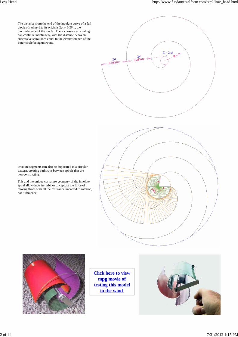
The distance from the end of the involute curve of a fullcircle of radius-1 to its origin is 2pi = 6.28..., thecircumference of the circle. The successive unwindingcan continue indefinitely, with the distance betweensuccessive spiral lines equal to the circumference of theinner circle being unwound.
Involute segments can also be duplicated in a circularpattern, creating pathways between spirals that arenon-constricting.
This and the unique curvature geometry of the involutespiral allow ducts in turbines to capture the force ofmoving fluids with all the resistance imparted to rotation,not turbulence.
Click here to viewmpg movie of
testing this modelin the wind.
Low Head http://www.fundamentalform.com/html/low_head.html
2 of 11 7/31/2012 1:15 PM
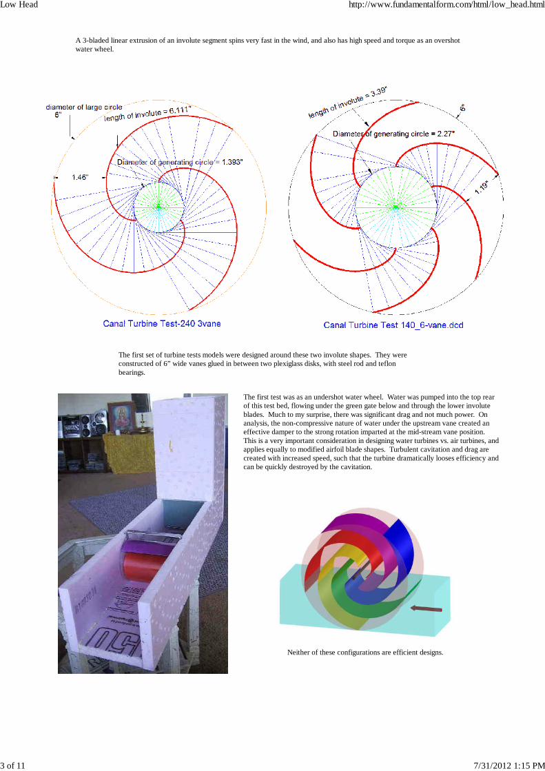
A 3-bladed linear extrusion of an involute segment spins very fast in the wind, and also has high speed and torque as an overshotwater wheel.
The first set of turbine tests models were designed around these two involute shapes. They wereconstructed of 6” wide vanes glued in between two plexiglass disks, with steel rod and teflonbearings.
The first test was as an undershot water wheel. Water was pumped into the top rearof this test bed, flowing under the green gate below and through the lower involuteblades. Much to my surprise, there was significant drag and not much power. Onanalysis, the non-compressive nature of water under the upstream vane created aneffective damper to the strong rotation imparted at the mid-stream vane position. This is a very important consideration in designing water turbines vs. air turbines, andapplies equally to modified airfoil blade shapes. Turbulent cavitation and drag arecreated with increased speed, such that the turbine dramatically looses efficiency andcan be quickly destroyed by the cavitation.
Neither of these configurations are efficient designs.
Low Head http://www.fundamentalform.com/html/low_head.html
3 of 11 7/31/2012 1:15 PM
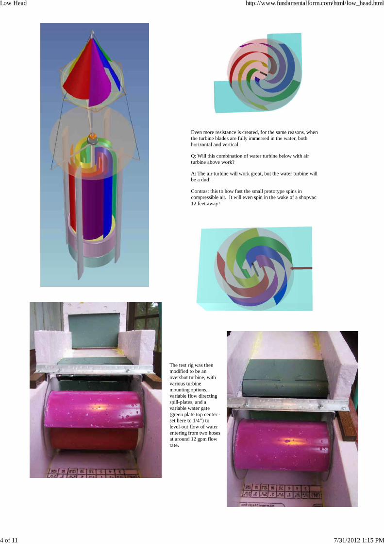
Even more resistance is created, for the same reasons, whenthe turbine blades are fully immersed in the water, bothhorizontal and vertical.
Q: Will this combination of water turbine below with airturbine above work?
A: The air turbine will work great, but the water turbine willbe a dud!
Contrast this to how fast the small prototype spins incompressible air. It will even spin in the wake of a shopvac12 feet away!
The test rig was thenmodified to be anovershot turbine, withvarious turbinemounting options,variable flow directingspill-plates, and avariable water gate(green plate top center -set here to 1/4”) tolevel-out flow of waterentering from two hosesat around 12 gpm flowrate.
Low Head http://www.fundamentalform.com/html/low_head.html
4 of 11 7/31/2012 1:15 PM
Click here for a video of testing both turbine configurations in overshot testbed.
This design has the unique property of providing higher torque as more power is being taken from the turbine, due to the greater amount and weight ofcaptured water that is being pulled down by gravity and contributing to the spin of the turbine.
Here are preliminary (not scientifically rigorous) results from the above tests:
•3 vanes 240degree, 1/4" gate = 139 rpm………circumference speed = 218ft/min = 136% of entering water speed•6 vanes 140degree, 1/4" gate = 149rpm……….circumference speed = 234ft/min = 145% speed of entering water•6 vanes 140degree, 3/16" gate = 147rpm……..circumference speed = 231ft/min = 143% speed of entering water (smoother but slower)
The above configuration is diagramed below as a 6-vaned 200degree involute 3ft diameter turbine with narrow inlet channel.
Low Head http://www.fundamentalform.com/html/low_head.html
5 of 11 7/31/2012 1:15 PM
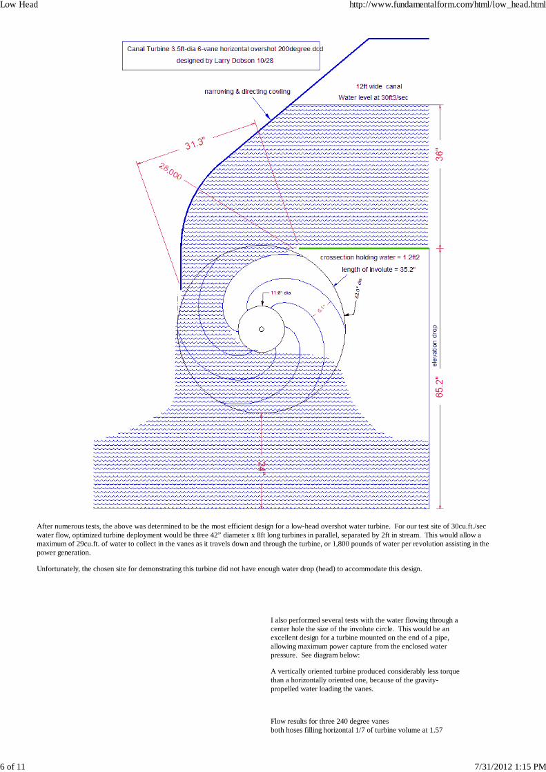
After numerous tests, the above was determined to be the most efficient design for a low-head overshot water turbine. For our test site of 30cu.ft./secwater flow, optimized turbine deployment would be three 42” diameter x 8ft long turbines in parallel, separated by 2ft in stream. This would allow amaximum of 29cu.ft. of water to collect in the vanes as it travels down and through the turbine, or 1,800 pounds of water per revolution assisting in thepower generation.
Unfortunately, the chosen site for demonstrating this turbine did not have enough water drop (head) to accommodate this design.
I also performed several tests with the water flowing through acenter hole the size of the involute circle. This would be anexcellent design for a turbine mounted on the end of a pipe,allowing maximum power capture from the enclosed waterpressure. See diagram below:
A vertically oriented turbine produced considerably less torquethan a horizontally oriented one, because of the gravity-propelled water loading the vanes.
Flow results for three 240 degree vanesboth hoses filling horizontal 1/7 of turbine volume at 1.57
Low Head http://www.fundamentalform.com/html/low_head.html
6 of 11 7/31/2012 1:15 PM
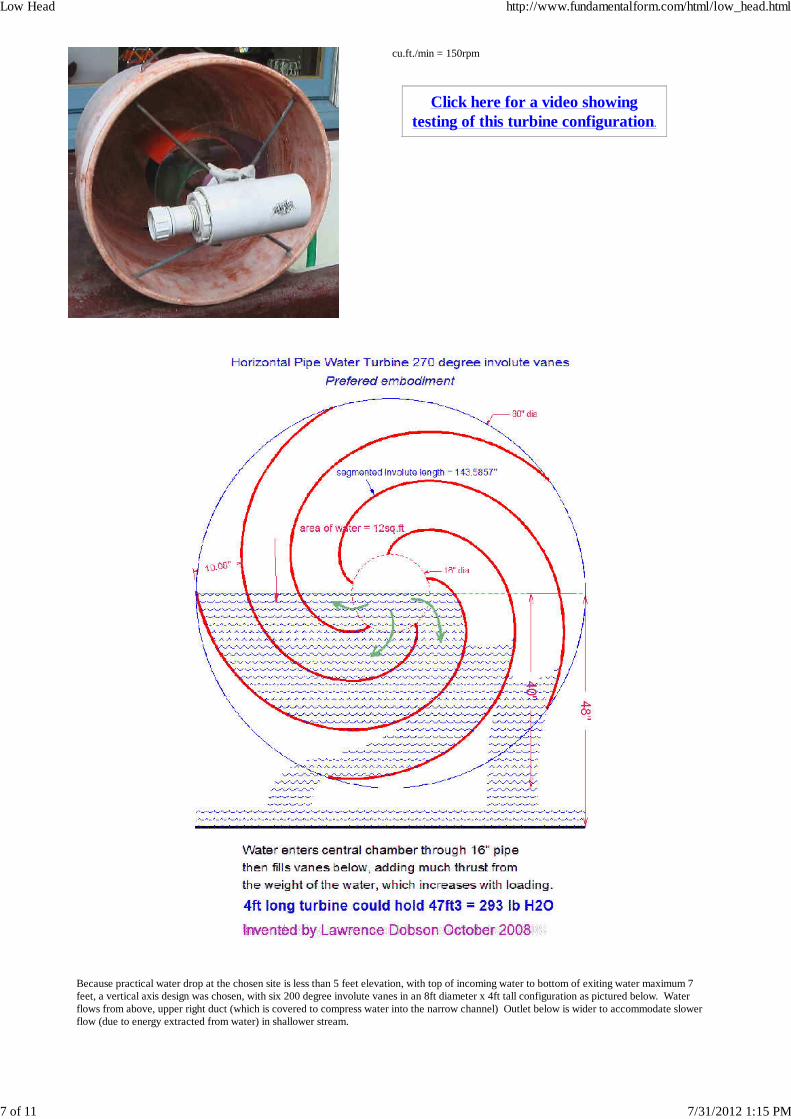
cu.ft./min = 150rpm
Click here for a video showingtesting of this turbine configuration.
Because practical water drop at the chosen site is less than 5 feet elevation, with top of incoming water to bottom of exiting water maximum 7feet, a vertical axis design was chosen, with six 200 degree involute vanes in an 8ft diameter x 4ft tall configuration as pictured below. Waterflows from above, upper right duct (which is covered to compress water into the narrow channel) Outlet below is wider to accommodate slowerflow (due to energy extracted from water) in shallower stream.
Low Head http://www.fundamentalform.com/html/low_head.html
7 of 11 7/31/2012 1:15 PM
To download a detailed dimension PDF drawing of this design, click here.
Low Head http://www.fundamentalform.com/html/low_head.html
8 of 11 7/31/2012 1:15 PM
The 3ft diameter horizontal axis turbine drawing above is designed to fit within the elevation drop parameters of the site.
STUDY THE OVERALL DIMENSIONS TO DETERMINE IF THIS IS INDEED POSSIBLE! The canal will flow through aconstriction, SLOPING FROM BELOW, to accelerate the water to around 100ft/sec at minimum depth of 14”.
5/20/09 ~ a high-volume flow test was conducted pouring from a 5gal bucket to augment the faucet flow.
Total flow through a 1” deep gate valve was 52.7gal/min
ratio of 4' wide x 3'dia turbine to 6" wide x 6"dia turbine = 8 times as wide and 48 times the volume1" deep equivalent to 8" deep on 4' wide turbine48 x 52.7 equivalent to 2530 gal/min = 338 cu.ft./min = 5.6cu.ft./sec = 2/5th the flowusing only 48" x 6" ratio, = 451 cu.ft./min = 7.5cu.ft./sec = 1/2 the flowspeed at max flow = 200rpm, which figures to 400rpm when flow speed is doubled.
This test indicates that the 3’ x 4’ turbine will handle the required flow of 15cu.ft./sec if speed is doubled in the constrictor.
CLICK HERE TO SEE VIDEO OF HIGH-VOLUME FLOW TEST
Low Head http://www.fundamentalform.com/html/low_head.html
9 of 11 7/31/2012 1:15 PM
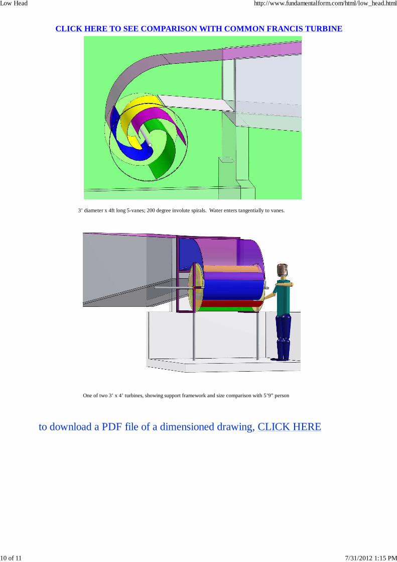
CLICK HERE TO SEE COMPARISON WITH COMMON FRANCIS TU RBINE
3’ diameter x 4ft long 5-vanes; 200 degree involute spirals. Water enters tangentially to vanes.
One of two 3’ x 4’ turbines, showing support framework and size comparison with 5’9” person
to download a PDF file of a dimensioned drawing, CLICK HERE
Low Head http://www.fundamentalform.com/html/low_head.html
10 of 11 7/31/2012 1:15 PM
The above concept drawing shows a test prototype of a drag-propulsion sail boat propelled by an involutespiral wind turbine, which should revolutionize sailboat design by creating very smooth and high efficiencytransfer of wind energy to pushing the water between the split hull of the boat. When the boat is anchored ina current, it can be generating electricity. The same mechanism can be used to extract power from anyshallow moving water when anchored in-stream. The multiple paddles are pulled through the water alongtracks by cables which direct them around pulleys and up out of the water as they return to the front.
For more details on this boat design, CLICK HERE
Low Head http://www.fundamentalform.com/html/low_head.html
11 of 11 7/31/2012 1:15 PM
[Low Head] [Other Turbines] [Final Drawings]
From http://en.wikipedia.org/wiki/Francis_turbine
Francis Turbine and generator Guide vanes at full flow setting (cut-away view)
The Francis turbine is a reaction turbine, which means that the working fluid changes pressure as it moves through the turbine, giving up its energy. A casement isneeded to contain the water flow. The turbine is located between the high pressure water source and the low pressure water exit, usually at the base of a dam.
The inlet is spiral shaped. Guide vanes direct the water tangentially to the runner. This radial flow acts on the runner vanes, causing the runner to spin. The guidevanes (or wicket gate) may be adjustable to allow efficient turbine operation for a range of water flow conditions.
As the water moves through the runner its spinning radius decreases, further acting on the runner. Imagine swinging a ball on a string around in a circle. If the stringis pulled short, the ball spins faster. This property, in addition to the water's pressure, helps inward flow turbines harness water energy.
Large Francis turbines are individually designed for each site to operate at the highest possible efficiency, typically over 90%.
Francis type units cover a wide head range, from 20 meters to 700 meters and their output varies from a few kilowatt to 1,000 megawatt.
In addition to electrical production, they may also be used for pumped storage; where a reservoir is filled by the turbine (acting as a pump) during low powerdemand, and then reversed and used to generate power during peak demand.
Francis turbines may be designed for a wide range of heads and flows. This, along with their high efficiency, has made them the most widely used turbine in theworld. Grand Coulee Dam uses a Francis Turbine.
COMPARED TO INVOLUTE TURBINE:
Requires much higher head (at least 5 times), pipe delivery at high speedwater delivered and redirected in complex compressing channelsgravity not utilizedwater pushes only to inside of vanes, not all the way throughflow is reversed only 140? degrees compared to 480 degrees of involute canal turbinesurface area of vanes much smallerflow not as streamlined and turbulence-freeWE SHOULD BE ABLE TO GET 90% EFFICIENCY TOO!
Banki turbine
From Wikipedia, the free encyclopedia
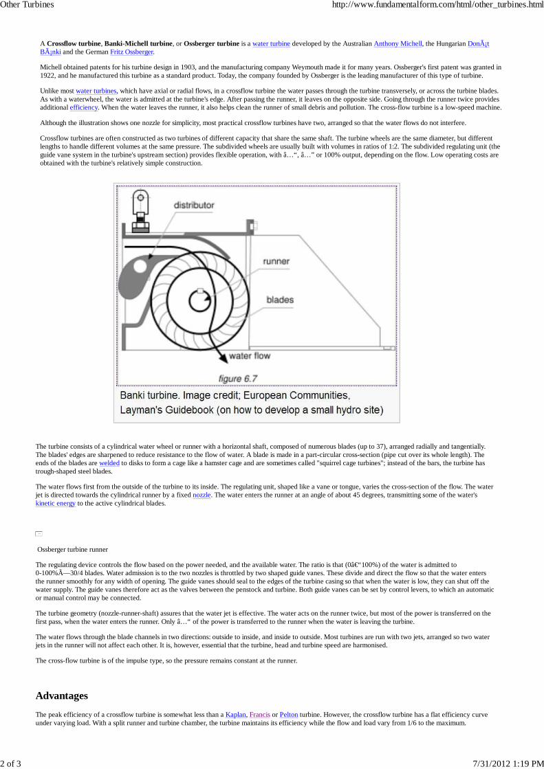
Banki turbine. Image credit; European Communities, Layman's Guidebook (on how to develop a small hydro site)
Other Turbines http://www.fundamentalform.com/html/other_turbines.html
1 of 3 7/31/2012 1:19 PM
A Crossflow turbine, Banki-Michell turbine, or Ossberger turbine is a water turbine developed by the Australian Anthony Michell, the Hungarian DonátBánki and the German Fritz Ossberger.
Michell obtained patents for his turbine design in 1903, and the manufacturing company Weymouth made it for many years. Ossberger's first patent was granted in1922, and he manufactured this turbine as a standard product. Today, the company founded by Ossberger is the leading manufacturer of this type of turbine.
Unlike most water turbines, which have axial or radial flows, in a crossflow turbine the water passes through the turbine transversely, or across the turbine blades.As with a waterwheel, the water is admitted at the turbine's edge. After passing the runner, it leaves on the opposite side. Going through the runner twice providesadditional efficiency. When the water leaves the runner, it also helps clean the runner of small debris and pollution. The cross-flow turbine is a low-speed machine.
Although the illustration shows one nozzle for simplicity, most practical crossflow turbines have two, arranged so that the water flows do not interfere.
Crossflow turbines are often constructed as two turbines of different capacity that share the same shaft. The turbine wheels are the same diameter, but differentlengths to handle different volumes at the same pressure. The subdivided wheels are usually built with volumes in ratios of 1:2. The subdivided regulating unit (theguide vane system in the turbine's upstream section) provides flexible operation, with â…“, â…” or 100% output, depending on the flow. Low operating costs areobtained with the turbine's relatively simple construction.
The turbine consists of a cylindrical water wheel or runner with a horizontal shaft, composed of numerous blades (up to 37), arranged radially and tangentially.The blades' edges are sharpened to reduce resistance to the flow of water. A blade is made in a part-circular cross-section (pipe cut over its whole length). Theends of the blades are welded to disks to form a cage like a hamster cage and are sometimes called "squirrel cage turbines"; instead of the bars, the turbine hastrough-shaped steel blades.
The water flows first from the outside of the turbine to its inside. The regulating unit, shaped like a vane or tongue, varies the cross-section of the flow. The waterjet is directed towards the cylindrical runner by a fixed nozzle. The water enters the runner at an angle of about 45 degrees, transmitting some of the water'skinetic energy to the active cylindrical blades.
Ossberger turbine runner
The regulating device controls the flow based on the power needed, and the available water. The ratio is that (0–100%) of the water is admitted to0-100%×30/4 blades. Water admission is to the two nozzles is throttled by two shaped guide vanes. These divide and direct the flow so that the water entersthe runner smoothly for any width of opening. The guide vanes should seal to the edges of the turbine casing so that when the water is low, they can shut off thewater supply. The guide vanes therefore act as the valves between the penstock and turbine. Both guide vanes can be set by control levers, to which an automaticor manual control may be connected.
The turbine geometry (nozzle-runner-shaft) assures that the water jet is effective. The water acts on the runner twice, but most of the power is transferred on thefirst pass, when the water enters the runner. Only â…“ of the power is transferred to the runner when the water is leaving the turbine.
The water flows through the blade channels in two directions: outside to inside, and inside to outside. Most turbines are run with two jets, arranged so two waterjets in the runner will not affect each other. It is, however, essential that the turbine, head and turbine speed are harmonised.
The cross-flow turbine is of the impulse type, so the pressure remains constant at the runner.
Advantages
The peak efficiency of a crossflow turbine is somewhat less than a Kaplan, Francis or Pelton turbine. However, the crossflow turbine has a flat efficiency curveunder varying load. With a split runner and turbine chamber, the turbine maintains its efficiency while the flow and load vary from 1/6 to the maximum.
Other Turbines http://www.fundamentalform.com/html/other_turbines.html
2 of 3 7/31/2012 1:19 PM
Since it has a low price, and good regulation, crossflow turbines are mostly used in mini and micro hydropower units less than two thousand kW and with headsless than 200 m.
Particularly with small run-of-the-river plants, the flat efficiency curve yields better annual performance than other turbine systems, as small rivers' water isusually lower in some months. The efficiency of a turbine determine whether electricity is produced during the periods when rivers have low heads. If theturbines used have high peak efficiencies, but behave poorly at partial load, less annual performance is obtained than with turbines that have a flat efficiencycurve.
Due to its excellent behaviour with partial loads, the crossflow turbine is well-suited to unattended electricity production. Its simple construction makes it easierto maintain than other turbine types; only two bearings must be maintained, and there are only three rotating elements. The mechanical system is simple, sorepairs can be performed by local mechanics.
Another advantage is that it can often clean itself. As the water leaves the runner, leaves, grass etc. will not remain in the runner, preventing losses. So althoughthe turbine's efficiency is somewhat lower, it is more reliable than other types. No runner cleaning is normally necessary, e.g. by flow inversion or variations ofthe speed. Other turbine types are clogged easily, and consequently face power losses despite higher nominal efficiencies.
BANKI TURBINE COMPARED TO INVOLUTE TURBINE:
all of the advantages of the Banki Turbine are present in the involute turbinesurface area of vanes much less than involutegravity not utilized with captured mass of waterwater pushes on upper vanes, then falls through center, creating turbulencewith water falling on inside of lower blades, debris could collect easier than involute, where water stays in vane to bottomflow is not reversed, extracting less power from waterdouble-pass flow through narrow vanes not as streamlined and turbulence-free as involuteWE SHOULD BE ABLE TO GET MUCH HIGHER EFFICIENCIES WITH VARYING STREAM FLOW!
Other Turbines http://www.fundamentalform.com/html/other_turbines.html