12
Date:08/03/17 Rev.:2.3 IOCard Displays II Manual
Date:08/03/17 Rev.:2.3
IOCard Displays II Manual

IOCard Displays II Manual
www.opencockpits.com 2
Index:
IOCARD DISPLAYS II MANUAL.................................................................................................................. 1
INDEX:.......................................................................................................................................................... 2
INTRODUCTION: ......................................................................................................................................... 3
DISPLAYS II: ............................................................................................................................................... 3 Components and outline:...................................................................................................................... 3 Connector's description: ....................................................................................................................... 4
INPUTS: ...................................................................................................................................................... 4 Displays direct to Displays II card: ....................................................................................................... 5 Displays conected through Opencockpits PCB´s:................................................................................ 5
TESTING THE CARD: .................................................................................................................................... 6 SOFTWARE INSTALLATION AND CONFIGURATION: .......................................................................................... 9
Variables definition and displays use: .................................................................................................. 9 Special characters and brightness: .................................................................................................... 10 Practical example: .............................................................................................................................. 10
LINKS OF INTEREST: ............................................................................................................................... 12
IOCard Displays II Manual
www.opencockpits.com 3
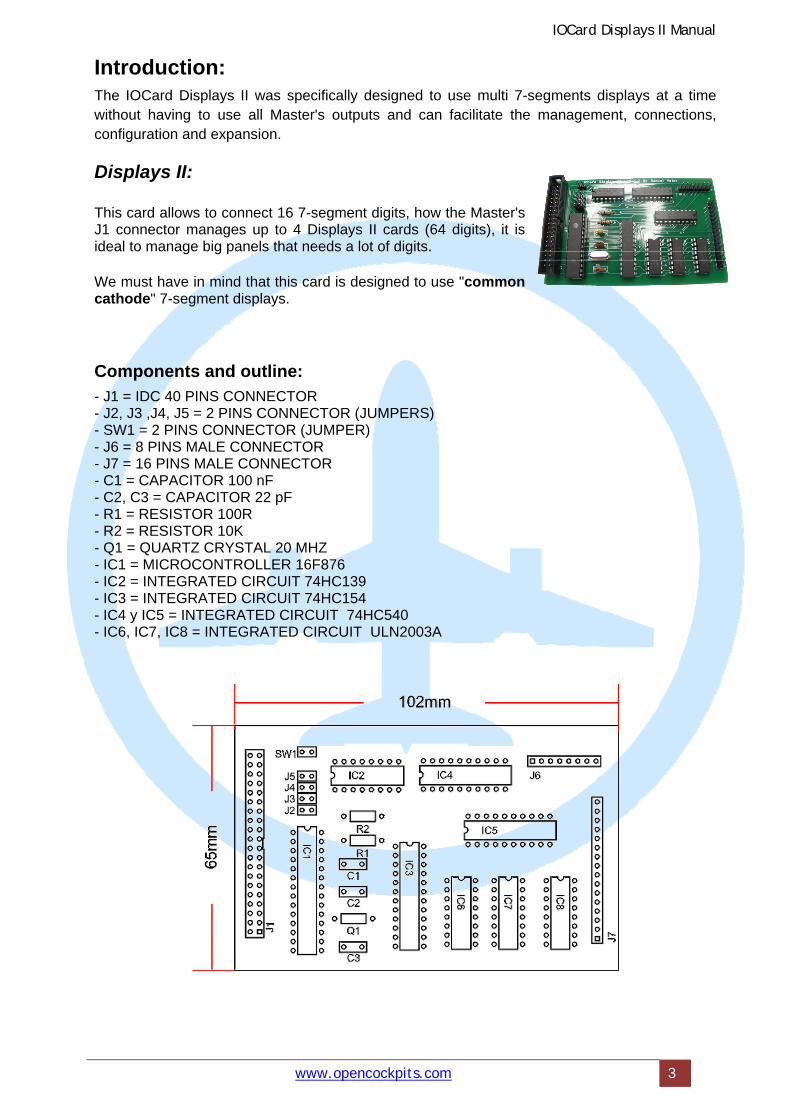
Introduction: The IOCard Displays II was specifically designed to use multi 7-segments displays at a time without having to use all Master's outputs and can facilitate the management, connections, configuration and expansion.
Displays II:
This card allows to connect 16 7-segment digits, how the Master's J1 connector manages up to 4 Displays II cards (64 digits), it is ideal to manage big panels that needs a lot of digits.
We must have in mind that this card is designed to use "common cathode" 7-segment displays.
Components and outline:
- J1 = IDC 40 PINS CONNECTOR - J2, J3 ,J4, J5 = 2 PINS CONNECTOR (JUMPERS) - SW1 = 2 PINS CONNECTOR (JUMPER) - J6 = 8 PINS MALE CONNECTOR - J7 = 16 PINS MALE CONNECTOR - C1 = CAPACITOR 100 nF - C2, C3 = CAPACITOR 22 pF - R1 = RESISTOR 100R - R2 = RESISTOR 10K - Q1 = QUARTZ CRYSTAL 20 MHZ - IC1 = MICROCONTROLLER 16F876 - IC2 = INTEGRATED CIRCUIT 74HC139 - IC3 = INTEGRATED CIRCUIT 74HC154 - IC4 y IC5 = INTEGRATED CIRCUIT 74HC540 - IC6, IC7, IC8 = INTEGRATED CIRCUIT ULN2003A

IOCard Displays II Manual
www.opencockpits.com 4
Connector's description:
• J1 = INPUT DATA CONNECTOR FROM MASTER CARD. • J2, J3 ,J4, J5 = JUMPERS FOR DISPLAYS II IDENTIFICATION SELECTION. • SW1 = NOT USED. • J6 = 7-SEGMENTS OUTS. • J7 = COMMON CATHODE INPUTS.
Inputs: The inputs from Master card are builded with flat 40 contacts cable, that is to say we use old hard disk IDE cables with IDC connectors. How each Master card can manage up to 4 Displays II, we have to select wich Displays II card conected we want to use, for that we will use the J2 to J5 jumpers. That is to say, we will change the jumpers to select the displays order as shown:
Closed jumper Card order Displays numbers
J2 1st 0-15
J3 2nd 16-31
J4 3rd 32-47
J5 4th 48-63
How we see at the photo:
IOCard Displays II Manual
www.opencockpits.com 5
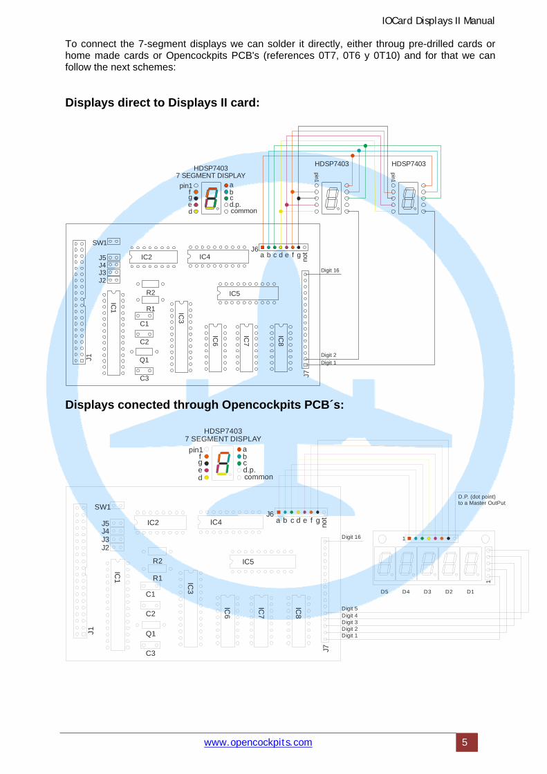
To connect the 7-segment displays we can solder it directly, either throug pre-drilled cards or home made cards or Opencockpits PCB's (references 0T7, 0T6 y 0T10) and for that we can follow the next schemes:
Displays direct to Displays II card:
R2
a
a
b
b
c
cd.p.common
d
d
e
e
f
fpin1
g
g
not
R1
SW1
HDSP7403HDSP7403
7 SEGMENT DISPLAY
HDSP7403
J5
pin1
pin1
J6
Digit 1
Digit 2
Digit 16J4J3J2
IC3
IC1
IC5
IC4IC
8
IC7
IC6
IC2
J1
J7
C1
C2
Q1
C3
Displays conected through Opencockpits PCB´s:
R2
a
a
b
b
c
cd.p.common
d
d
e
e
f
fpin1
g
g
not
R1
SW1
HDSP74037 SEGMENT DISPLAY
J5J6
1
D1D2D3D4D5
D.P. (dot point)to a Master OutPut
1
Digit 1Digit 2Digit 3Digit 4Digit 5
Digit 16J4J3J2
IC3
IC1
IC5
IC4
IC8
IC7
IC6
IC2
J1
J7
C1
C2
Q1
C3
IOCard Displays II Manual
www.opencockpits.com 6
The feeding for displays comes from Master's bus (40 contacts flat cable). It is obvious that Master card must be 5V feeded. The examples shown above are designed for Agilent HDSP displays, that are compatibles with Opencockpits displays, but we can modify the connections for a different pinout, the only condition is that the displays must be "common cathode". In the case we use the displays decimal point (D.P.), this point can be connected directly to a Master's output and is not necessary to connect the common or connect a resistor because the Displays II works in multiplexed mode, for that 7-segment displays will never suffer overloads avoiding segment meltings.
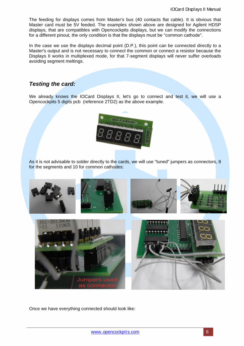
Testing the card:
We already knows the IOCard Displays II, let's go to connect and test it, we will use a Opencockpits 5 digits pcb (reference 2TD2) as the above example.
As it is not advisable to solder directly to the cards, we will use "tuned" jumpers as connectors, 8 for the segments and 10 for common cathodes:
Once we have everything connected should look like:
IOCard Displays II Manual
www.opencockpits.com 7
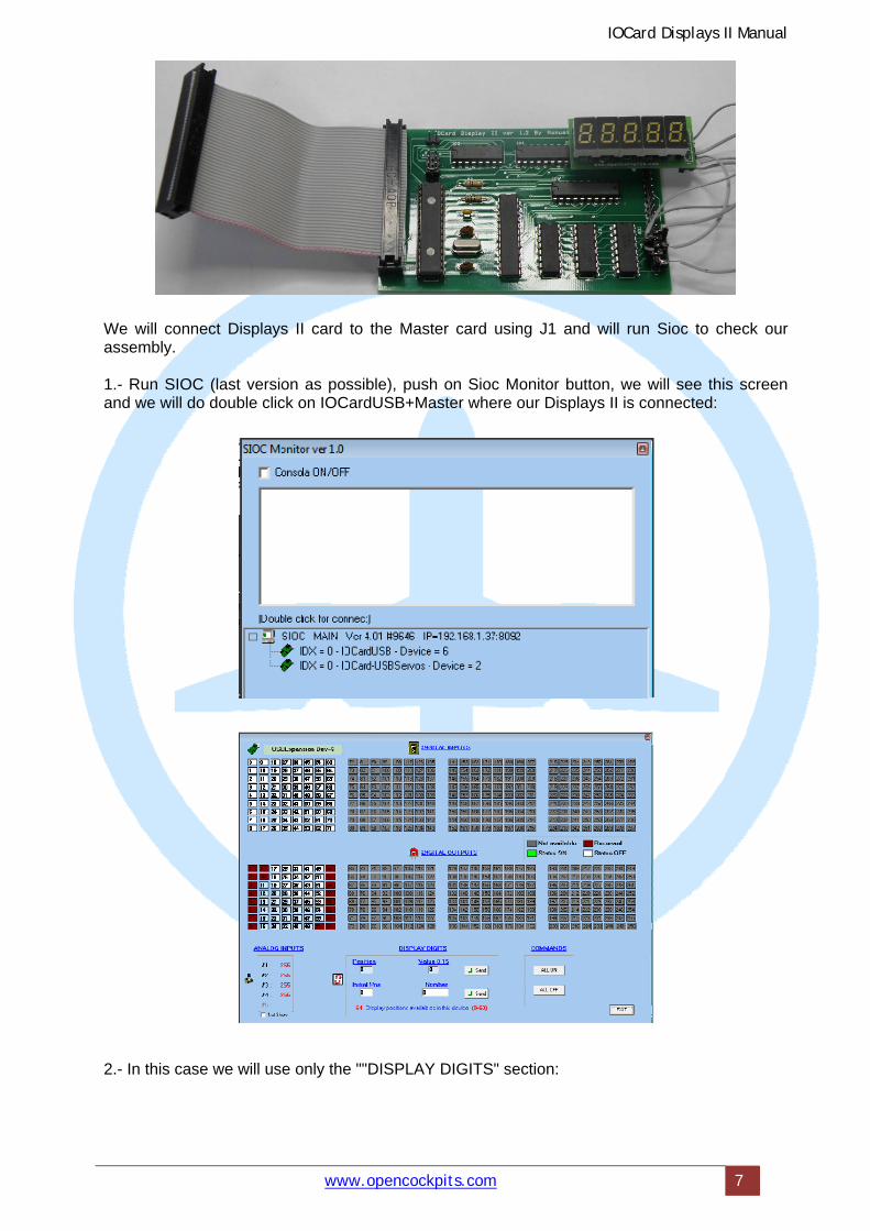
We will connect Displays II card to the Master card using J1 and will run Sioc to check our assembly. 1.- Run SIOC (last version as possible), push on Sioc Monitor button, we will see this screen and we will do double click on IOCardUSB+Master where our Displays II is connected: 2.- In this case we will use only the ""DISPLAY DIGITS" section:
IOCard Displays II Manual
www.opencockpits.com 8
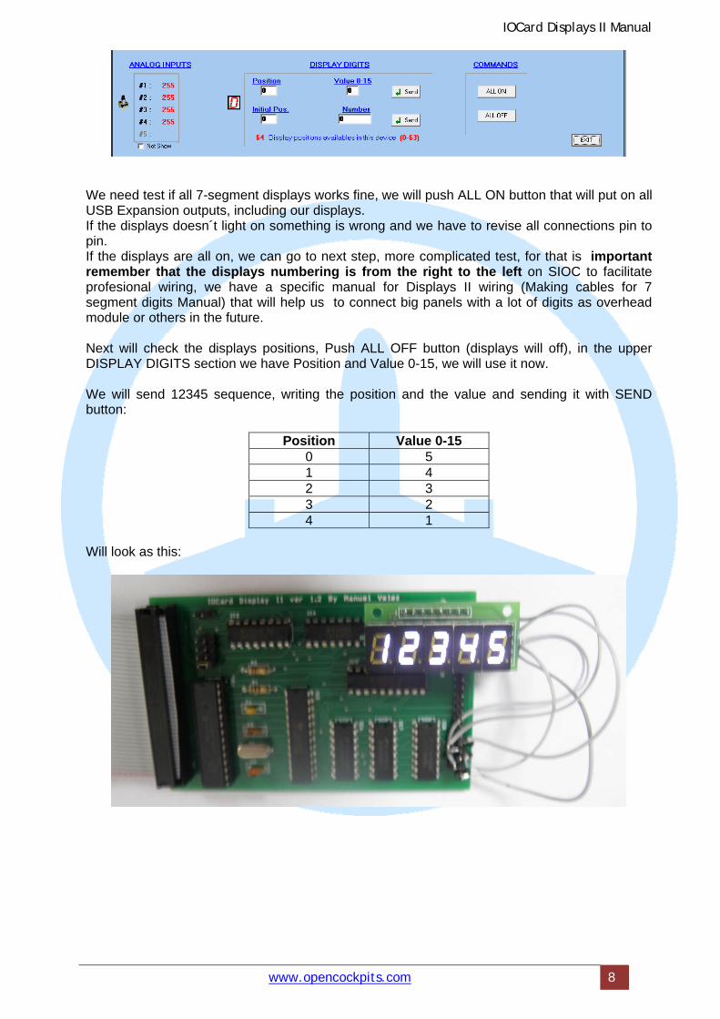
We need test if all 7-segment displays works fine, we will push ALL ON button that will put on all USB Expansion outputs, including our displays. If the displays doesn´t light on something is wrong and we have to revise all connections pin to pin. If the displays are all on, we can go to next step, more complicated test, for that is important remember that the displays numbering is from the right to the left on SIOC to facilitate profesional wiring, we have a specific manual for Displays II wiring (Making cables for 7 segment digits Manual) that will help us to connect big panels with a lot of digits as overhead module or others in the future. Next will check the displays positions, Push ALL OFF button (displays will off), in the upper DISPLAY DIGITS section we have Position and Value 0-15, we will use it now. We will send 12345 sequence, writing the position and the value and sending it with SEND button:
Position Value 0-15 0 5 1 4 2 3 3 2 4 1
Will look as this:

IOCard Displays II Manual
www.opencockpits.com 9
Software installation and configuration: Already knows how to check Displays II cards and 7-segment displays, now we have to program it on SIOC, we will need following software: SIOC, Flight Simulator as FS2004, FS2009, FSX, Xplane, etc., Necessary plugins for simulator, Etc. At the end of this document there is a list of links to download the necessary software to put into practice this manual.
Variables definition and displays use:
Look some theory, the digit's variable declaration: Var 0001, Name digit_0, Link IOCARD_DISPLAY, Device 0, Digit 0, Numbers 1 Device, IDX number of USBExpansion where is connected the Displays II card. Digit, less signifiant physical digit (the righter digit or units) of cipher we want to use. Numbers, represents how many digits we want to send to display. If we want put "5" at righter digit, we only have to assign "5" to the variable: v0001 = 5 or digit_0 = 5 to use more than a digit we have in mind the next: Imagine that we have to send the captains MCP heading (three digits), that turns from 0 to 359 degrees: Var 1000 // captain's heading { &HDG = v1000 } Var 3000, Name HDG, Link IOCARD_DISPLAY, Device 0, Digit 0, Numbers 3 This code means that variable v3000 (HDG) will show V1000 value at display placed on device 0 (our only Master connected), starting from digit 0 (less value or righter digit of three 7-segments display), using 3 displays (0, 1 & 2). We must remember that we have to assembly the displays all together in this order: 2, 1, 0.
IOCard Displays II Manual
www.opencockpits.com 10
Special characters and brightness:
To visualize special characters we can use specific codes on SIOC as shown: -999999 = digit off, -999998 = digit shows "-", -999997 = digit shows "6" (with upper segment on), -999996 = digit shows "t", -999995 = digit shows "d", -999994 = digit shows "_", Also we can control the brightness of the digits using the value -999994 and then sending the brightness value bettween 0 and 15.
Practical example:
// ***************************************************************************** // * Config_SIOC ver 4.01 - By Manuel Velez - www.opencockpits.com // ***************************************************************************** // * FileName : test_displays1.txt // * Date : 15/03/2012 Var 0002, Link IOCARD_SW, Input 1 // switch status { IF V0002 = 1 { V0008 = 1 // led on V0003 = 1 // 1 on digit 0 V0004 = 2 // 2 on digit 1 V0005 = 3 // 3 on digit 2 V0006 = 4 // 4 on digit 3 V0007 = 5 // 5 on digit 4 } ELSE { V0008 = 0 // led off V0003 = -999999 // display off V0004 = -999999 // display off V0005 = -999999 // display off V0006 = -999999 // display off V0007 = -999999 // display off } } Var 0003, Link IOCARD_DISPLAY, Digit 0, Numbers 1 Var 0004, Link IOCARD_DISPLAY, Digit 1, Numbers 1 Var 0005, Link IOCARD_DISPLAY, Digit 2, Numbers 1 Var 0006, Link IOCARD_DISPLAY, Digit 3, Numbers 1 Var 0007, Link IOCARD_DISPLAY, Digit 4, Numbers 1 Var 0008, Link IOCARD_OUT, Output 11 // end of file test_displays1.txt How we can see the operation is to easy: -First we declare tha variable connected to the switch wich will activate or deactivate the displays and indicator LED that will indicate if switch is on or off, then we will send the values for show 12345 cipher.

IOCard Displays II Manual
www.opencockpits.com 11
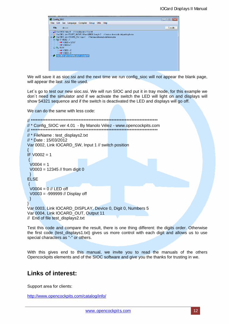
-At the first IF condition we can see that switch connected to input "1", when is activated (value 1) sends to variable v0008 value 1 to activate the LED and send the desired values to the variable digits v0003, 4, 5, 6 & 7. -If the switch value is 0, then sends to v0008 variable the value 0 that is necessary to off the led indicator and also send off code to the digit's variables v0003, 4, 5, 6 & 7. Save the file and run it on SIOC, push CONFIG button. Config_sioc will run with a blank .ssi page. We will create a new sioc.ssi from our test_displays1.txt file. We will select the test_displays1.txt file and will appear this: A compilation log We already see that file compilation is done on three stages. Always so. When everything is ok a green OK is shown. This reveals that all gone well, if a red cross appears this will mean that there is something wrong, for example, we have forgotten a } or a = sign or have a broken line. This occurs often when we copy a fragment of file. Then, we close the log compilation clicking on the OK button and now we will see our script on Sioc window converted in .ssi format. We will se something like:
IOCard Displays II Manual
www.opencockpits.com 12
We will save it as sioc.ssi and the next time we run config_sioc will not appear the blank page, will appear the last .ssi file used. Let´s go to test our new sioc.ssi. We will run SIOC and put it in tray mode, for this example we don´t need the simulator and if we activate the switch the LED will light on and displays will show 54321 sequence and if the switch is deactivated the LED and displays will go off. We can do the same with less code: // ***************************************************************************** // * Config_SIOC ver 4.01 - By Manolo Vélez - www.opencockpits.com // ***************************************************************************** // * FileName : test_displays2.txt // * Date : 15/03/2012 Var 0002, Link IOCARD_SW, Input 1 // switch position { IF V0002 = 1 { V0004 = 1 V0003 = 12345 // from digit 0 } ELSE { V0004 = 0 // LED off V0003 = -999999 // Display off } } Var 0003, Link IOCARD_DISPLAY, Device 0, Digit 0, Numbers 5 Var 0004, Link IOCARD_OUT, Output 11 // End of file test_displays2.txt Test this code and compare the result, there is one thing different: the digits order. Otherwise the first code (test_displays1.txt) gives us more control with each digit and allows us to use special characters as "-" or others. With this gives end to this manual, we invite you to read the manuals of the others Opencockpits elements and of the SIOC software and give you the thanks for trusting in we.
Links of interest: Support area for clients: http://www.opencockpits.com/catalog/info/


