IODINE COLLECTION STUDIES -A REVIEW R. Dennis, L. Silverman, and F. Stein Harvard School of Public Health ABSTRACT Results of past iodine collection studies conducted by the Harvard Air Clean- ing Laboratory under AEC contract are reviewed briefly. Performance data not previously reported are given for metal and mineral collectors {fibrous and gran- ular) under a variety of operating conditions. Major test objectives are to deter- mine which media afford optimum removal of radioactive iodine from laboratory, process, or reactor gas streams. Although activated carbon, silver nitrate- coated Berl saddles, and caustic scrubbers have been used successfully in certain applications, none of these meet all of the following requirements: (1) 90 to 99. 9% removal of iodine, (2) low resistance to air flow, (3) extended service life - up to two years, (4) operational at temperatures up to 300°C, (5) corrosion resistant, and (6) noncombustible. Screening tests indicate that bronze, copper and silver plated-copper meshes are efficient collectors for high iodine concentrations, > 1 Mg. /M3, but erratic in performance when concentrations are low, 10- 6 Mg. /M3. Variability with low iodine concentrations is apparently related to the physical state of iodine, i. e. molecular, chemically complexed, or partic - ulate-adsorbed. Our data and that from other sources suggest that iodine aerosols will differ greatly in the field, depending upon the physical and chemical properties of other aerosol components, operating temperatures, and gas retention time prior to treatment. In order to designate by what mechanisms iodine is removed by a certain collector rigorous aerosol definition is required. Current ACL testing is de- signed to determine insofar as possible the behavior of molecular and particulate- adsorped iodine by analysis of iodine gas streams for particle size and number. All iodine generation techniques used in our studies will be evaluated. INTRODUCTION Iodine collection studies were first undertaken by the Harvard Air Cleaning Laboratory in 1956 at the request of the Sanitary Engineering and Environmental Group, Division of Reactor Development, U. S. Atomic Energy Commission. This investigation was included in the air and gas cleaning project (involving re- search, development, and evaluation of gas cleaning equipment) conducted at Harvard University under contract with the U. S. Atomic Energy Commission since 1948. -327-
Transcript
IODINE COLLECTION STUDIES - A REVIEW
R. Dennis, L. Silverman, and F. Stein Harvard School of Public Health
ABSTRACT
Results of past iodine collection studies conducted by the Harvard Air Cleaning Laboratory under AEC contract are reviewed briefly. Performance data not previously reported are given for metal and mineral collectors {fibrous and granular) under a variety of operating conditions. Major test objectives are to determine which media afford optimum removal of radioactive iodine from laboratory, process, or reactor gas streams. Although activated carbon, silver nitratecoated Berl saddles, and caustic scrubbers have been used successfully in certain applications, none of these meet all of the following requirements: (1) 90 to 99. 9% removal of iodine, (2) low resistance to air flow, (3) extended service life - up to two years, (4) operational at temperatures up to 300°C, (5) corrosion resistant, and (6) noncombustible. Screening tests indicate that bronze, copper and silver plated-copper meshes are efficient collectors for high iodine concentrations,
> 1 Mg. /M3, but erratic in performance when concentrations are low, 10-6 Mg. /M3. Variability with low iodine concentrations is apparently related to the physical state of iodine, i. e. molecular, chemically complexed, or partic -ulate-adsorbed. Our data and that from other sources suggest that iodine aerosols will differ greatly in the field, depending upon the physical and chemical properties of other aerosol components, operating temperatures, and gas retention time prior to treatment.
In order to designate by what mechanisms iodine is removed by a certain collector rigorous aerosol definition is required. Current ACL testing is designed to determine insofar as possible the behavior of molecular and particulateadsorped iodine by analysis of iodine gas streams for particle size and number. All iodine generation techniques used in our studies will be evaluated.
INTRODUCTION
Iodine collection studies were first undertaken by the Harvard Air Cleaning Laboratory in 1956 at the request of the Sanitary Engineering and Environmental Group, Division of Reactor Development, U. S. Atomic Energy Commission. This investigation was included in the air and gas cleaning project (involving research, development, and evaluation of gas cleaning equipment) conducted at Harvard University under contract with the U. S. Atomic Energy Commission since 1948.
-327-
At the inception of our research program, it had been established by various investigators that activated charcoal (1) (2), silver nitrate-coated saddles (3), and caustic scrubbers (4) (5) would provide satisfactory collection of radioactive iodine for certain process off-gases. However, it did not appear that the above techniques would be suitable for treating large gas volumes discharging at elevated temperatures which might be anticipated from reactor ventilation or cooling air systems, or from special reactor designs. Aside from the inherent problems of cost, size, and resistance to gas flow associated with scale-up, the combustibility of carbon and large scrubbing liquid demands suggested that dry collection be explored. Furthermore, it appeared that the functions of particulate collection and iodine removal might be consolidated within a single device with proper selection of materials. Results of preliminary tests by this laboratory showed that silver plating (chemical) of 4 micron diameter mineral wool fibers afforded iodine collection efficiencies greater than 90. 0 per cent. Although the plating was not satisfactory due to non-uniform distribution and short service life, the tests demonstrated the feasibility of a heat resistant, fiber matrix coated with an active iodine adsorbent. In the event that the collector were to be designed solely for iodine removal, it was desired that the required adsorbing surface occupy a relatively small volume and operate at very low gas flow resistance.
From the onset of our experiments, it was apparent that in addition to high temperature-high volume systems there was a need for efficient, economical iodine collectors in many other processes. Radioactive iodine is usually present in off-gases from dissolvers, uranium and plutonium separations, and contaminated exhaust air from hot laboratory facilities. Under certain conditions, it may also appear in reactor cooling air. Gas volume requirements may vary anywhere from 100 to 400, 000 cu. ft. per minute or greater and temperatures may range from ambient to 1500°C for certain air or gas cooled reactor effluents. The variety of applications indicated that development of a universal iodine collector was very unlikely. However, to guide research in a direction consistent with existing needs, the following tentative performance criteria were established for iodine collection equipment by Silverman, et al (4).
1. Efficiency of at least 90 per cent for control of continuous low level omissions and greater than 99, 99 per cent where hazardous situations may arise.
2. Retention of several grams of radioactive iodine with no significant change in resistance or efficiency.
3. Unmaintained filter life of two years, if possible.
4. Effective operation at temperatures ranging from ambient to 300°C.
5. Minimal interference by materials such as oxides of nitrogen, nitric acid mists, ammonia, hydrogen fluoride, hydrogen chloride or other corrosive substances and organics found iri dissolver and other off-gases.
6. Operation at face velocities of at least l foot per second with a resistance less than 1 inch of water. Should gas volumes be low, however, higher resistance might be acceptable.
-328-
7. Minimal space requirement for adaptation to existing ducts or piping.
8. Fireproof or resistant to both decay heat and combustion.
The various methods of iodine collection investigated by this laboratory were selected on the basis that they would at least fulfill certain specific applications. It was obvious that activated charcoal and organic plastic fibers would be unsuitable for high temperature operation and that hydrogen fluoride would exclude use of mineral fibers. Results of initial screening tests reported by Silverman, et al (4) were based on collector rating with sublimed iodine-127. The low sensitivity of chemical methods (0. 1 mg I2 per cu. m. of air the minimum detectable quantity) required the use of high iodine concentrations, ::::=- 10 mg. per cu. m. in the test gas stream, approximately 1 o4 to 1 o7 times greater than might be expected in practice. On the basis of comparative tests, it was possible to exclude several materials which displayed low efficiencies, low holding capacities, or high resistances.
In test results reported previously (6) we found that a vacuum-plated silver coating on slag wool fibers showed the highest efficiency, > 99. 9 per cent, and lowest resistance, 1. 1 inch water, of the several chemical and metallic coatings investigated. These included KI, AgN03, Cd-Sb, and Ag.
Tests with metal ribbon (tin and copper) and zinc granules showed superior performance for copper at room temperature, ==- 99. 9 per cent efficient and < 0. 1 inch of water resistance at a face velocity of 1 foot per second. Copper ribbon, however, failed completely after 25 hours of hot operation at 300°C. Silver plated copper mesh displayed a slightly lower efficiency at room temperature, 99. 91 per cent, but showed no decrease in performance after 100 hours of continuous operation at 300°C. It was noted that the sHver plated copper, once used at 300°C, became a poor iodine collector when returned to room temperature, c::::: 31 per cent efficient. Continued high efficiency, > 99. 6 per cent, was attained, however, when gas temperature was again elevated to 300°C.
The presence of moisture and elevated temperatures resulted in higher efficiencies with both copper and silver-plated copper mesh confirming the fact that the primary iodine collecting mechanism was chemi-sorption. Our tests with gross iodine concentrations, > 10 mg. per cu. m. indicated that NH3, HN03, and H 2S did not interfere with iodine collection.
Of the several materials tested in the mineral adsorbent category - activated alumina, Attapulgus clay, Thirsty Glass (porous glass granules), silica gel, and uncoated slag wool fibers - none were more than 86 per cent efficient. Activated carbon was the only granular adsorbent showing high efficiencies, ::::=- 99. 98 per cent. A specially prepared rayon fiber, 250 denier, containing 40 per cent activated carbon by weight appeared to be nearly as effective as the activated carbon granules.
It was also noted that a 6-12 mesh silica gel impregnated with Rochelle salts to deposit an elemental silver coating yielded efficiencies in the range or those reported for activated carbon, 99. 92 per cent. Although we have not continued
-329-
testing of this particular collector, we think that it might be used to replace carbon when a potential fire hazard exists.
As a result of the screening tests, it was concluded that metal fiber meshes merited further study based upon the high efficiencies with I-127. Some of our test results which have been reported previously (6) are included in another section of this report since they had a direct bearing on later test procedures.
Test Equipment and Procedures
1. Equipment Arrangement
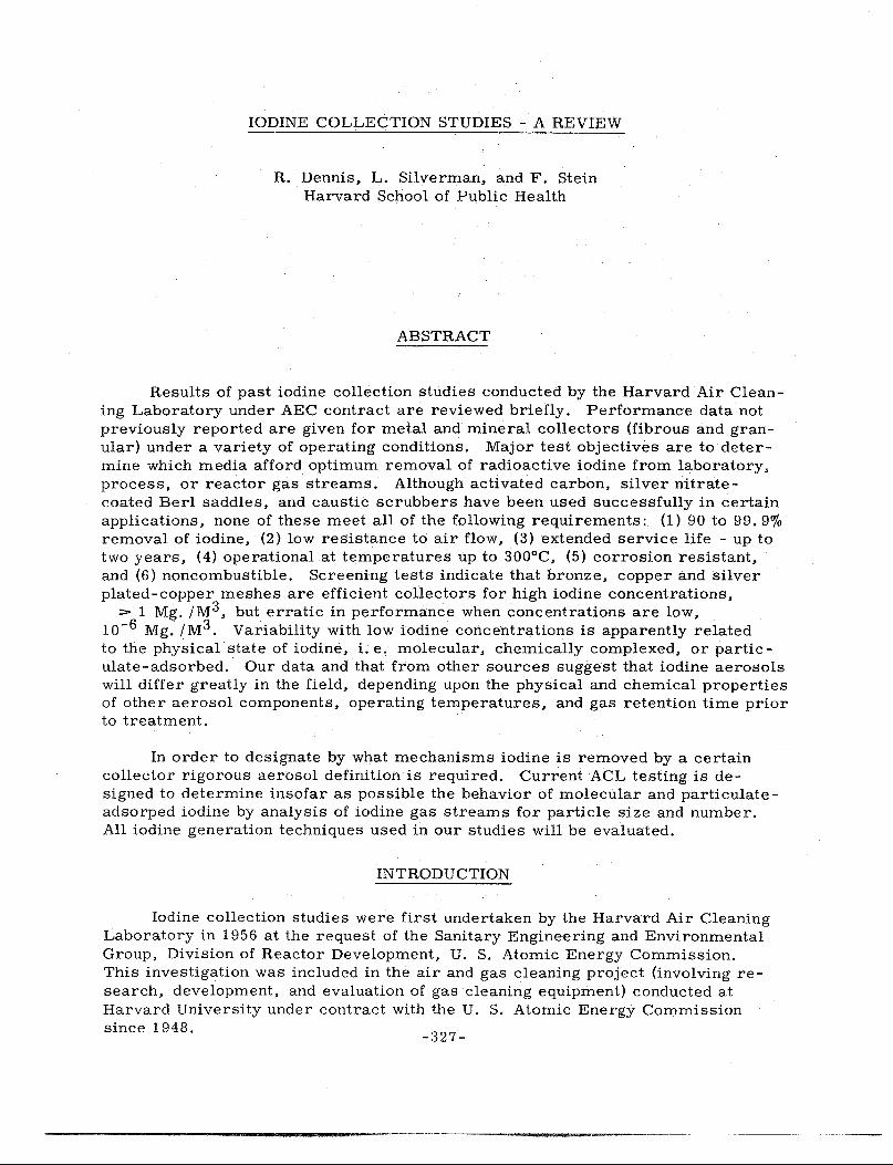
All tests reported here were conducted on a laboratory scale using the test apparatus illustrated in Figure 1. Fibrous or granular media were packed in 12 inch long Pyrex glass tubes, either 1 inch or 7 I 8 inch in diameter. All-glass joints were used in the later phases of the study to minimize wall adsorption problems. The gas stream containing the iodine aerosol (14 1 pm) was split immediately upstream of the inlet to the collector tube by a symmetrical "Y" tube so that half the stream was drawn to the upstream sampling unit. The remainder of the test aerosol, about 7 lpm, passed through the fibrous or granular bed and was collected in entirety as the downstream sample.
2. Iodine Generation
One method of generating iodine aerosols is shown in Figure 1. A solution of I-131 or a mixture of I-131 and I-127 in carbon tetrachloride was allowed to drip slowly into a heated "U 11 tube evaporator which was swept by prefiltered air. Air prefilters were removed when tests were to be conducted in the presence of normal background atmospheric dust concentrations. A second 11U 11 tube was connected in parallel with the evaporator tube for sublimation of I-127 crystals when high concentrations were desired. Production of an I-131 aerosol by heating Na I-131 to 400°C was conducted in similar equipment except that an electric heating element surrounded the 11 U 11 tube. This aerosol could also be fortified by placing a second 11 U 11 tube in parallel containing I-127 crystals.
In a few cases an additional filtration unit was installed immediately downstream of the Na I-131 decomposition tube to remove fine particulate matter produced by heating of Na I-131. An all-glass paper filter was ordinarily used for precleaning supply air. A special membrane type filter (10 mu pore diameter)':' was also investigated as a means of decreasing nuclei concentrations.
Based upon tests reported previously (6) (7), it was evident that the generation method and concentration of iodine in the gas stream would have considerable bearing on experimental results. Ideally, we would have preferred to conduct our studies under field conditions to obtairi realistic performance data. However, since our program was restricted to small scale laboratory tests, it was necessary to accept I-131 sources in whatever form available. Several methods of
~~Type VF, Millipore Filter Corporation, Bedford, Massachusetts, U. S. A.
-330-
I w w ..... I
LEGEND I GLASS TUBE-0.875
111.0., 12• LONG
2 SILVERED COPPER RIBBON
3 THERMOMETER
4 LEAD SHIELD
5 U-TUBE EVAPORATOR
6 TEFLON NEEDLE VALVE 7 IOOINE131 IN CCL4
8 BURET
9 BUBBLER
10 AIR FILTER
11 MANOMETER
12 SURGE BOTTLE
13 ORIFICE 14 LEIMAN PUMP
FIG. I - IODINE131 COLLECTION TEST APPARATUS
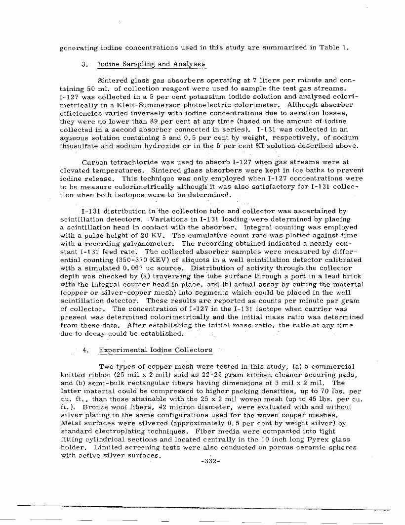
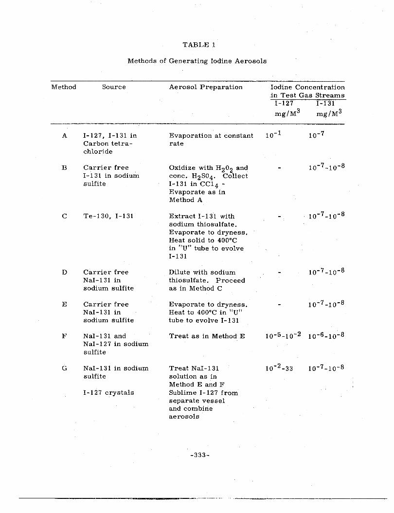
generating iodine concentrations used in this study are summarized in Table 1.
3. Iodine Sampling and Analyses
Sintered glass gas absorbers operating at 7 liters per minute and containing 50 ml. of collection reagent were used to sample the test gas streams. 1-127 was collected in a 5 per cent potassium iodide solution and analyzed colorimetrically in a Klett-Summerson photoelectric colorimeter.. Although absorber efficiencies varied inversely with iodine concentrations due to aeration losses, they were no lower than 89 per cent at any time (based on the. amount of iodine collected in a second absorber connected in series). 1-131 was collected in an aqueous solution containing 5 and O. 5 per cent by weight, respectively, of sodium thiosulfate and sodium hydroxide or in the 5 per cent KI solution described above.
Carbon tetrachloride was used to absorb I-127 when gas streams were at elevated temperatures. Sintered glass absorbers were kept in ice baths to prevent iodine release. This technique was only employed when 1-127 concentrations were to be measure colorimetrically although it was also satisfactory for I-131 collection when both isotopes were to be determined.
I-1 31 distribution in the collection tube and collector was ascertained by scintillation detectors. Variations in I-131 loading were determined by placing a scintillation head in contact with the absorber. Integral counting was employed with a pulse height of 20 KV. The cumulative count rate was plotted against time with a recording galvanometer. The recording obtained indicated a nearly constant I-131 feed rate~ The collected absorber samples were measured by differential counting (350""370 KEV) of aliquots in a well scintillation detector calibrated with a simulated O. 067 uc sou:tce. Distribution of activity through the collector depth was checked by (a) traversing the tube surface through a port in a lead brick with the integral counter head in place, and (b) actual assay by cutting the material (copper or silver-copper mesh) into segments which could be placed in the well scintillation detector. These results are reported as counts per minute per gram of collector. The concentration of I-127 in the I-131 isotope when carrier was present was determined colorimetrically and the initial mass ratio was determined from these data. After establishing the initial mass ratio, the ratio at any time due to decay could be established.
4. Experimental Iodine Collectors
Two types of copper mesh were tested in this study, (a) a commercial knitted ribbon (25 mil x 2 mil) sold as 22-25 gram kitchen cleaner scouring pads, and (b) semi-bulk rectangular fibers having dimensions of 3 mil x 2 mil. The latter material could be compressed to higher packing densities, up to 70 lbs. per cu. ft., than those attainable with the 25 x 2 mil woven mesh (up to 45 lbs. per cu. ft.). Bronze wool fibers, 42 micron diameter, were evaluated with and without silver plating in the same configurations used for the woven copper meshes. Metal surfaces were silvered (approximately 0. 5 per cent by weight silver) by standard electroplating techniques. Fiber media were compacted into tight fitting cylindrical sections and located centrally in the 10 inch long Pyrex glass holder. Limited screening tests were also conducted on porous ceramic spheres with active silver surfaces.
-332-
TABLE 1
Methods of Generating Iodine Aerosols
Method Source Aerosol Preparation Iodine Concentration in Test Gas Streams
I-127 1-131
mg/M3 mg/M3
A l - 12 7, l -1 31 in Evaporation at constant 10-1 10-7 Carbon tetra- rate chloride
B Carrier free Oxidize with H 2o2 and 10-7-10-8 1-131 in sodium cone. H2So 4. Collect sulfite 1-131 in CCl4 -
Evaporate as in Method A
c Te-130, 1-131 Extract 1-131 with 10-7-10- 8
sodium thiosulfate. Evaporate to dryness. Heat solid to 400°C in "U" tube to evolve 1-131
D Carrier free Dilute with sodium 10-7 -10- 8
Nal-131 in thiosulfate. Proceed sodium sulfite as in Method C
E Carrier free Evaporate to dryness. 10-7 -10-8 Nal-131 in Heat to 400°C in "U" sodium sulfite tube to evolve 1-131
F Nal-131 and Treat as in Method E 10-5-10-2 10-6-10-8 Nal-127 in sodium sulfite
G Nal-131 in sodium Treat Nal-131 10-2 -33 10-7-10-8 sulfite solution as in
Method E and F 1-127 crystals Sublime I-127 from
separate vessel and combine aerosols
-333-
Test Results
1. Miscellaneous Metal Meshes
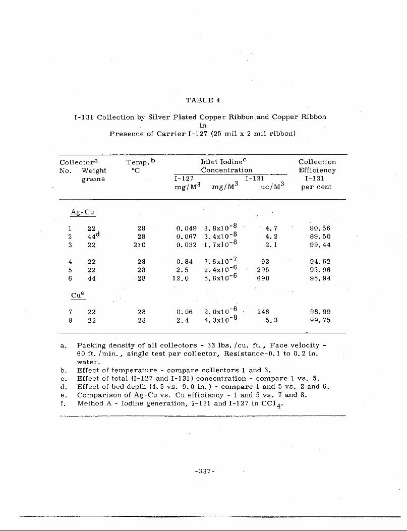
Tests on several types of metal fiber units, Table 2, indicate I-131 collection efficiencies in the range of 95-99 per cent for a carrier-free aerosol. Earlier tests (4) Table 4 showed approximately the same results for iodine concentrations (I-131 and I-127) 107-108 times larger. Extrapolation of the latter values in conjunction with observed efficiencies of greater than 99. 9 per cent for I-127 in. high (50 mg. /m3) concentrations indicated that very low-10-20 per cent efficiencies, should have been obtained when total iodine concentrations were in the range of 1 o-8 to 10-6 mg. /m 3.
It had also been expected that the greater surface area of the 2 x 3 mil Ag-Cu media would have resulted in improved performance relative to the 2 x 25 mil meshes. Contradictory effects were also noted for prefiltration of supply air, Tests 1-4, Table 2. Inconsistent performance was attributed to differences in method of aerosol generation as demonstrated by data presented later in this paper.
Qualitatively, a comparison of collectors in Table 2 does indicate that for similar flow rates (60 ft. per min. face velocity) the resistance of the 25 x 2 mil mesh is much lower than that for other metal fibers.
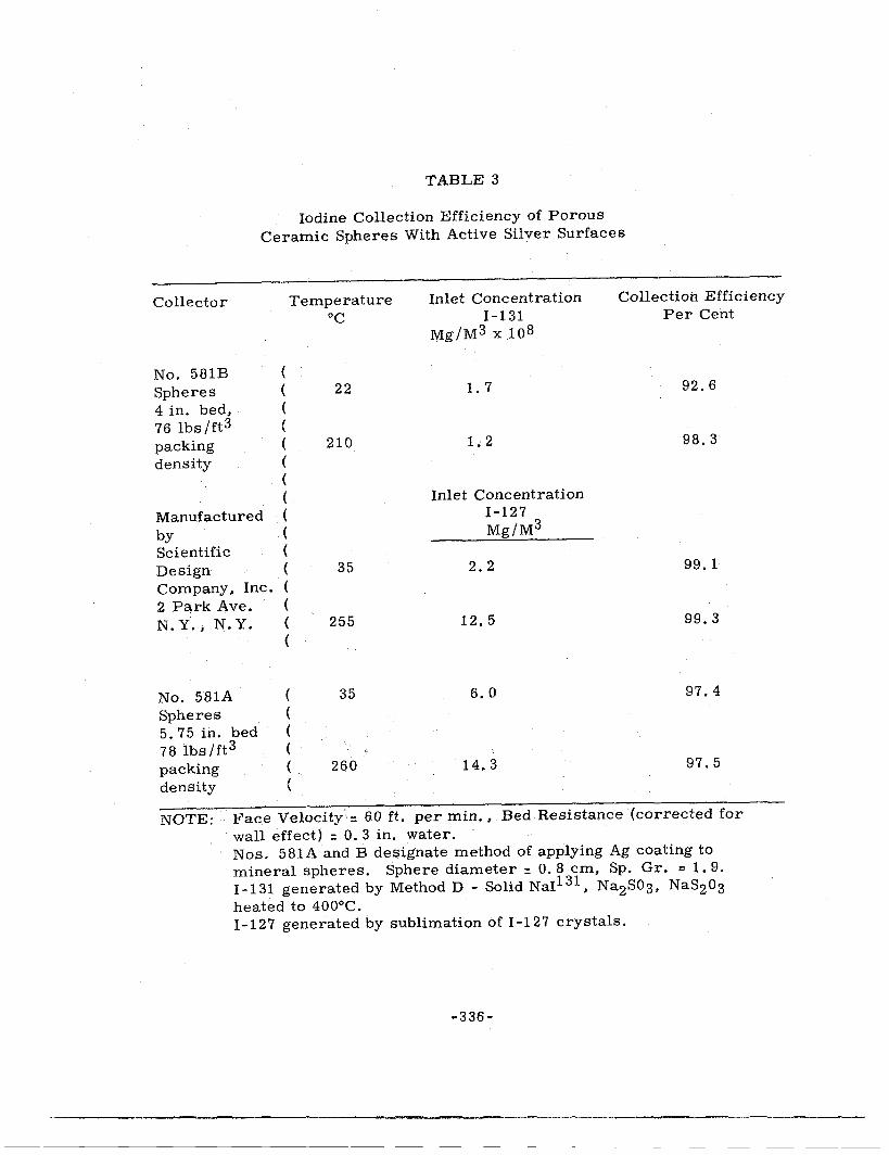
2. Porous Silver-Coated Ceramic Spheres
Results of limited screening tests on porous ceramic spheres with two types of silver coatings are shown in Table 3. Although the physical characteristics were about the same for No. 581A and 581B spheres*, the difference in method of applying the active silver surface was reflected in I-127 tests, i.e. 99. 2 and 97. 4 per efficient, respectively, for spheres 581 B and 581 A. Carrierfree iodine-131 tests on 581B media showed slightly lower efficiencies than those previously reported for Ag-Cu meshes.
3. Effect of Iodine Generation Method on Ag-Cu Mesh Efficiency
The tests reported in the following section depict mainly an extended study of iodine generation methods. Our primary objective was to determine which iodine generation technique would be most suitable for rating iodine collectors in the laboratory. A summary of our initial experiments with I-131 and Ag-Cu collectors has been presented in Table 4 since the results of these tests determined in large part the pattern for future investigations. It had not been expected that a reduction of total iodine concentration to the 1. 0 mg. per cu. m. range would have such a marked effect on collection efficiency. Although we had considered the fact that iodine and other gases could adsorb on atmospheric dust, the contact time between particulates and gas during transit from the generator to collector (0. 1 to 0. 2 sec.) appeared too brief for significant iodine adsorption.
>!<Scientific Design Co., Inc., 2 Park Ave., N. Y., N. Y.
- :-rn 4-
TABLE 2
IODINE-131 COLLECTION EFFICIENCY OF METALLIC RIBBON AND FIBERS
Test Collector Packing Resistance Inlet Concentration Collection b Bed
Number Densi?[ In. Water a I-131 3 8
Efficiency Temperature lbs /ft uc/m 3 mg/m xlO Percent oc
1 Ag-Cu 2 x 3 mils 44 1. 5 4.8 3.9 96.0 30
2 Ag-Cu 2 x 3 mils 44 1. 5 1. 4 1. 1 92.6c 30
3 Ag-Cu 2 x 3 mils 44 1. 5 1. 6 1. 3 99.0c 275
4 Ag-Cu 2 x 3 mils 22 0.3 11. 4 9. 3 98.2 275
I 5 ;:i!~~; :~1:sure d w 36 0. 2 1. 8 1. 5 95.9 30 w CJl I 6 Ag-Cu 2 x 25 mils
NOTE: Iodine Generated by Method E - Solid Nar131 and Na2so3 heated to 400°C
(a) Filtration velocity = 60 ft. per min. , Bed depth = 4 in. (b) Average of 2 to 3, 30 minute tests (c) Supply air prefiltered with 1106-B glass paper (d) Continuous room air filtration
Collector
No. 581B Spheres 4 in. bed, 76 lbs/ft3 packing density
TABLE 3
Iodine Collection Efficiency of Porous Ceramic Spheres With Active Silver Surfaces
( ( ( ( ( ( ( (
Temperature oc
22
210
Inlet Concentration I-131
Mg/M3 x 108
1. 7
1.2
Collection Efficiency Per Cent
92.6
98.3
Manufactured (
Inlet Concentration I-127 Mg/M3 by (
Scientific (
Design ( 35 2.2 99. 1
Company. Inc. (
2 Park Ave. (
N.Y.,N.Y. ( 255 12.5 99.3 (
No. 581A ( 35 6. 0 97.4
Spheres (
5. 75 in. bed (
78 lbs/ft3 (
packing ( 260 14. 3 97.5
density (
NOTE: Face Velocity = 60 ft. per min .• Bed Resistance (corrected for wall effect) = O. 3 in. water. Nos. 581A and B designate method of applying Ag coating to mineral spheres. Sphere diameter = O. 8 cm, Sp. Gr. c 1. 9. I-131 generated by Method D - Solid NaI131 • Na2S03, NaS203 heated to 400°C. I-12 7 generated by sublimation of I-12 7 crystals.
-336-
TABLE 4
I-131 Collection by Silver Plated Copper Ribbon and Copper Ribbon in
a. Packing density of all collectors - 33 lbs. /cu. ft., Face velocity -60 ft. /min., single test per collector, Resistance-0. 1 to 0. 2 in. water.
b. Effect of temperature - compare collectors 1 and 3. c. Effect of total (I-127 and I-131) concentration - compare 1 vs. 5. d. Effect of bed depth (4. 5 vs. 9. 0 in.) - compare 1 and 5 vs. 2 and 6. e. Comparison of Ag-Cu vs. Cu efficiency - 1 and 5 vs. 7 and 8. f. Method A - Iodine generation, I-131 and I-127 in CC1 4 .
-:337-
A large part of the iodine adsorbed on submicron particles, 0. 05 to O. 5 micron range would naturally be expected to penetrate the coarse fiber mesh based upon basic filtration theory.
Our tests with I-127 alone in large concentrations ( ::> 50 mg. per cu. m.) had shown no reduction in efficiency ( ::> 99. 9 per cent) when carbon tetrachloride vapor was injected into the gas stream simultaneously. In addition, diffusivity measurements of Chamberlain and Wiffen (7) indicated that molecular iodine was released by evaporating CCl4 solutions. However, the above findings do not necessarily imply that CCl4 vapors have no adverse effects when iodine concentrations are less than 50 mg. per cu. m. Accepting the data in Table 1 at face value the following conclusions can be drawn: (1) the collection efficiency for a given bed is a direct function of the iodine concentration in the gas stream; (2) doubling the length of the collector (9. 0 vs. 4. 5 inches) makes no improvement at all in collection efficiency; (3) maintaining the Ag-Cu bed at elevated temperature greatly improves collection effiCiency (90 to 99. 4 per cent); and (4) the copper mesh is superior to the silver plated copper when used at room temperature.
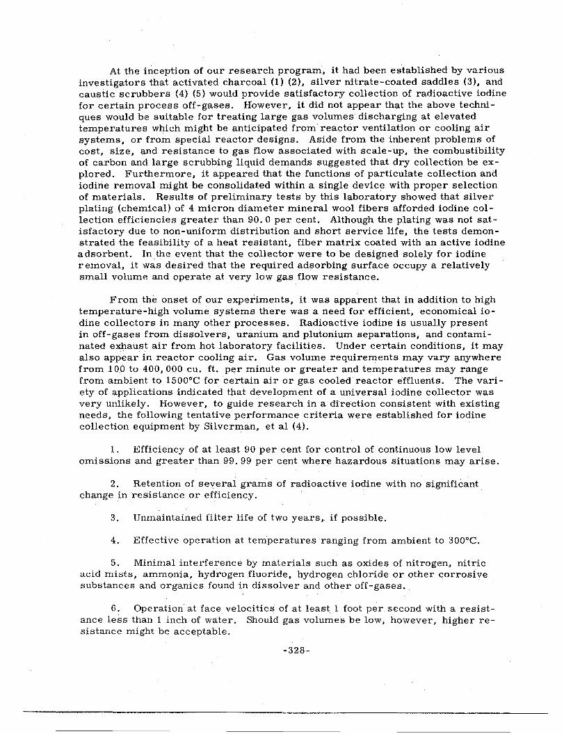
However, th~ mechanism of gaseous iodine collection by copper or silver is one of chem1- sorption wherein the iodine is irreversibly fixed as the metallic iodide at temperatures below 300°C. Accordingly, one should expect to find collection defined by the logarithmic-penetration law when the quantity of iodine is well below that required to saturate the collector surface. On this basis, a bed having the capacity to operate at 99. 99 per cent efficiency at high concentrations should perform at least as well at any lower concentration. It was interesting to note that when the collectors described in Table 4 were analyzed to determine the distribution of I-131 with respect to bed length, the bed efficiencies were actually found to be constant for approximately half their depth (Figure 2 ). Similar results have been reported by AEC (ORNL) and AERE (Harwell) studies. This has led to the conclusion that I-131 and I-127 in a purely gaseous form is readily collectable, 99. 99 per cent, and is represented in proportions essentially the same as those in the parent gas stream by the material deposited on the metal fibers. Since overall collection efficiency was in the 90-95 per cent range, it was further concluded that a 5 to 10 per cent fraction of the iodine mixture did not exist as molecular iodine, but rather as a particulate-adsorbed or chemically-complexed substance which adsorbed ineffectually on the collector .surface. These hypotheses appeared to explain why increasing the bed depth caused no measurable increase in efficiency. Improvement of efficiency at elevated temperature might be attributed solely to the rate of increase of the chemical reaction between iodine and the metal except for the fact tha.t efficiency measurements for gaseous iodine collection in the 99. 9+ per cent range were already indicated by bed activity distribution. It also seemed possible that desorption of iodine from particulates or decomposition of some iodine complex to liberate molecular iodine might have contributed to the higher efficiencies.
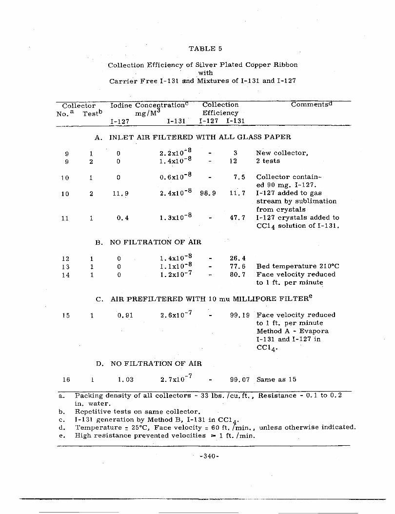
When a carrier-free I-131 solution in carbon tetrachloride, prepared by Method B, was injected into the test gas stream, I-131 collection efficiency fell to very low levels, 3 to 12 per cent (see Table 5), Prior loading of a test collector with 90 mg, of I-127 did not alter the efficiency although in theory one
-338-
a:: 0 ..... 0 w ...J ....I 0 0 i... 0
2 <: Ct: 0
:::::: w ... -
102------------------------~-----------~-
s
2
FACE VELOCITY• 60FT.IMIN. PACKING DENSITY• 33 LBS./ F'T 3 TEMPERATURE• 2s•c TOTAL IODINE INLET
10 1 t---+--LOADING(ll27+1131) • 2S MG/M3
OVERALL 1131 COLLECTION EFF ICIE NC Y • 96 t-
2
100..,__-+-+-------t----~-+------t--~~-+-~
s
2 t----_,...o:-----t-----T----t-----·--·--··· --·
10·1 1---~------------------l,__ ___ ~·-···
2 ~----------------i----··········--! I
10·2 ~: --------------~-!
5 I
2
10·3------------------------.. -· 0 2 3 4 "" COLLECT OR DEPTH· INCf-IE S
FIGURE 2. 1001NEl3I DISTRIBUTION WITHIN 5 INCH BED oi: Sil.VEA PLATED COPPER RIBBON
-339-
TABLE 5
Collection Efficiency of Silver Plated Copper Ribbon with
Carrier Free I-131 and Mixtures of I-131 and I-127
Collector No. a Testb
Iodine ConcentrationC mg/M3
Collection Efficiency
I-127 I-131
Commentsd
9 9
10
10
11
12 13 14
15
16
1 2
1
2
1
1 1 1
1
1
I-127 I-131
A. INLET AIR FILTERED WITH ALL GLASS PAPER
0 2. 2xl0.;. 8
0 1. 4x10⁻⁸
0 o.6x10- 8
11. 9 2.4xlo-8 98.9
0.4 1.3xlo-8
B. NO FILTRATION OF AIR
0 0 0
1. 4xlo-8
1. lx10-8 1. 2xlo-7
3 12
7.5
11. 7
47.7
26.4 77.6 80.7
New collector, 2 tests
Collector contain-ed 90 mg. I-127. I-127 added to gas stream by sublimation from crystals I-127 crystals added to CCl4 solution of I-131.
Bed temperature 210°C Face velocity reduced to 1 ft. per minute
C. AIR PREFILTERED WITH 10 mu MILLIPORE FILTERe
0.91 2.6xlo-7
D. NO FILTRATION OF AIR
1. 03 2.7x10- 7
99. 19 Face velocity reduced to 1 ft. per minute Method A - Evapora I -1 31 and I - 1 2 7 in CCl4.
99. 07 Same as 15
a. Packing density of all collectors - 33 lbs. I cu. ft., Resistance - 0. 1 to 0. 2 in. water.
b. Repetitive tests on same collector. c. I-131 generation by Method B, I-131 in CCl . d. Temperature = 25°C, Face velocity = 60 ft. f min., unless otherwise indicated. e. High resistance prevented velocities > 1 ft. /min.
-340-
might expect a preferential retention of 1-12 7 if the iodine were physically, rather than chemically, adsorbed. However, past tests had shown that a rather stable iodine complex must form on the metal surface since desorption was negligible below 300°C. When large concentrations of I-127 were added in conjunction with low concentrations of I-131, apparent differences in isotopic separation were noted. It was not clear whether results of Test 2 on Collector 10 were due to experimental error or to the fact that the I-12 7 phase was prepared separately by sublimation of crystals. 1-131 efficiency for Collector 11 appeared to be in closer agreement with carrier free tests.
It should be noted that the air supply was filtered with high efficiency allglass paper prior to entering the test systems for Collectors 9 through 11. Even though absolute particle removal was not obtained, it seemed that a partial removal of adsorption nuclei should have increased the relative concentration of molecular iodine and hence led to higher collection efficiency. According to tests on Collector 12, the opposite occurred, i. e .. the presence of dust particles appeared to be an adjunct to I-131 collection. On the other hand, when air velocity was reduced by a factor of 60, to 1 fL per minute, a significant increase in I-131 efficiency was noted, 26 to 81 per cent. This test, Collector 14, indicated that a large part of the I-131 was associated with particulate material which could be collected by diffusion to fiber surfaces at low gas velocities.
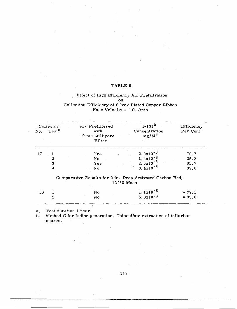
In view of the inconsistent data reported in Table 5, we decided to investigate other means of aerosol generation. Substituting Method C for I-131 generation, i. e. heating a sodium thiosulfate-sodium iodide-131 mixture to 400°C, we used a highly efficient prefilter (10 mu pore size Millipore filter) to screen out atmospheric particulates. Tests 1 through 4, Table 6, again demonstrated that some form of contamination, gas or dust present in normal atmospheric air, interferred with I-131 collection efficiency. As a matter of comparison, it was also confirmed that activated carbon was the best available iodine collector, Collector 18.
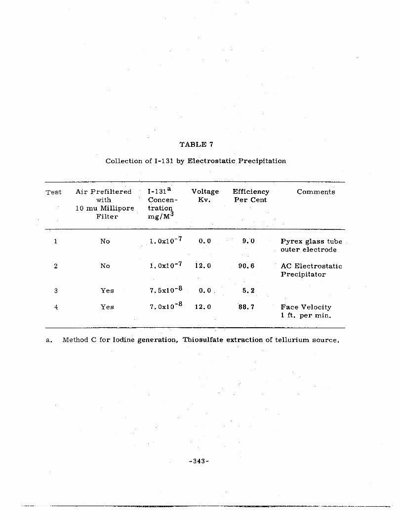
In an attempt to find out whether gaseous or particulate components of atmospheric aerosols were complexing agents for I-131, filtered and unfiltered air containing I-131 was passed through an A. C. electrostatic precipitator, Table 7.
With no filtration of air and no voltage on the precipitator, Test 1 indicated poor iodine retention, 9. 0 per cent. In contrast, with 12 KV across the electrode system and no filtration (Test 2) I-131 collection efficiency was increased to 90. 6 per cent.
Essentially the same results were obtained, however, when the air was prefiltered, Tests 3 and 4. Since an electrostatic precipitator is principally a particulate collector, it appeared that the I-131 generator itself was contributing solid particles to the system. Furthermore, insofar as very low concentrations of I-131 were concerned (1 o-7 to 1 o-8 mg. per cu. m.) a large fraction of the total iodine appeared to be attached in some manner to these solids.
-341-
Collector No. Testa
17 1 2 3 4
TABLE 6
Effect of High Efficiency Air Prefiltration on
Collection Efficiency of Silver Plated Copper Ribbon Face Velocity : 1 ft. /min.
Air Prefiltered with
10 mu Millipore Filter
Yes No Yes No
l-131b Concentration
mg/M3
2.ox10-8
1. 4xl o-8 2.5x10⁻⁸
3.4xlo-8
Efficiency Per Cent
70.7 35. 8 61. 7 39.0
Comparative Results for 2 in. Deep Activated Carbon Bed, 12/30 Mesh
18 1 2
a. Test duration 1 hour.
No No
1. lxl0-8
5.0xlo-8 > 99.1 > 99. 8
b. Method C for Iodine generation, Thiosulfate extraction of tellurium source.
-342-
TABLE 7
Collection of 1-131 by Electrostatic Precipitation
Test Air Prefiltered I-131a Voltage Efficiency Comments with Concen- Kv. Per Cent
2 No 1. oxio-7 12.0 90.6 AC Electrostatic Precipitator
3 Yes 7.5x10⁻⁸ o. 0 ' 5. 2
4 Yes 7. Oxl0-8 12.0 88.7 Face Velocity 1 ft. per min.
a. Method C for Iodine generation, Thiosulfate extraction of tellurium source.
-343-
At this point we changed to Method E for iodine generation, previously used by Chamberlain and Wiffen (7). We also decided to eliminate all prefiltering of air during the test series shown in Table 8 on the premise that the results would at least be conservatively low.
Our initial tests with carrier free 1-131 (lo-7 to 10-8 mg. per cu. m.) were very promising, Tests 1 and 2 on Collector 19, Table 8. Since the trend toward improved efficiencies with increasing iodine concentrations had been exhibited in all past studies, it was decided to fortify the Na 1-131 with Na 1-127 in amounts which would take us up to the 0. 1 to 1. 0 mg. per cu. m. range for total iodine concentration. As shown by tests 1 - 5 in Table 8, the collection efficiency increase was not very encouraging if at all significant, 96 to 97 per cent. However, since results of Table 7 suggested nuclei release from the iodine generator, we decided to introduce I-127 by sublimation of I-127 crystals in a parallel circuit to eliminate introduction of particulates from Na 1-127 decomposition. Based upon Tests 1 through 4 on Collector 20, introduction of 1-127 by sublimation yielded high collection efficiencies, ::..- 99. 5 per cent, when total iodine (l-131 and 1-127) concentrations.were ii;i the 10-2 to 1 mg. per cu. m. range. These results were considerably better than those reported for similar concentration ranges with iodine evolved from carbon tetrachloride, Method A (90 to 95 per cent). In addition there did not appear to be a significant isotopic difference in the collection of 1-131 and I-127, Collector 22, Test 1.
At the conclusion of tests reported in Table 8, we thought that we had sue -ceede.d in producing a test gas stream composed principally of molecular iodine. Although we did not believe that this aerosol typified field emissions, we did feel that it might enable the investigator to define the nature of the various iodine collection mechanism.
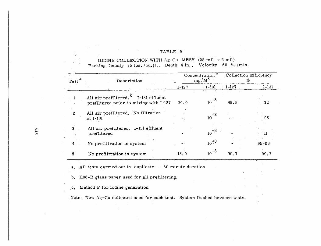
A final group of tests,were performed to determine whether prefiltration of air would show improved collection efficiencies relative to those outlined in Table 8. It is immediately seen from Table 9, .that the previously stated hypothesis, i. e. particulate adsorption of molecular iodine leads to lowered collection efficiency is contradicted. With prefiltration of all air entering the parallel branches of the iodine generator and filtration of the effluent from 1-131 "U" tube (Test 1) collection efficiency for 1-131 was only 22 per cent. in contrast to 99. 8 per cent for I-127. Theoretically, the filtration process should have caused a significant reduction in the concentration of adsorption nuclei. Removal of the special filter in the I-131 branch of the generator circuit, while still prefiltering all inlet air to the generator (Test 2) yielded the same 95 per cent efficiencies noted in Table 8 for I-131. However, as soon as we replaced the filter in the I-131 circuit (Test 3) the collection efficiency again reverted to low levels, 11 per cent. At the pres -ent time we have no sound explanation for this behavior. Obviously some change occurred in either the chemical or physical state of the I-131 as a result of the filtration process. If, for example, Na20 were formed during the decomposition of Na I-131 and subsequently hydrolyzed the presence of an alkali hydroxide film on the Ag-Cu surface might improve collection. (Sodium hydroxide in past tests was a very effective iodine collector.) Another possibility might be the formation of iodine-sulfur compounds as the result of sodium sulfite decomposition, which
·344-
TABLE 8
Effect of Iodine Generation Method and Iodine Concentration on Collection Efficiency of Ag-Cu Mesh
Collector No. Test
Time Min.
Inlet Concentration mg/M3
Collection Efficiency
19
20
21
22
1-131 1-127 1-131 1-127
Iodine Generation - Method E (Decomposition of Nal-131 and Nal-127)
1 30 7. 7x10- 8 95.95
2 30 6. 68x10-7 95.62
3 30 1. 07xio-7 l. l2x10-5 95.44
4 30 1. 02xio-7 8. 65x10-4 97.20
5 30 3.16xlo-6 2. 92xio-2 97.28
Iodine Generation - Method F (Sublimation of 1-127 and Decomposition ofNaI-131)
1 30 1.36xro-8 97.07
2 60 1. 84x10- 7 0.086 99.77
3 60 1.52x10⁻⁷ 0.268 99.75
4 30 8. 8 xio-8 1. 25 99.48
1 30 32.2 99.89
1 30 3.05xlo- 7 33.0 99.89 99.77
NOTE: Collector - Silver plated "Chore Girl", 22 grams, 4 in. bed depth, packing density = 35 lbs. /cu. ft., face velocity = 60 ft. /min.
-345-
I C>.l
*" Q')
I
TABLE 9
IODINE COLLECTION WITH Ag-Cu MESH (25 mil x 2 mil) Packing Density 35 lbs. I cu. ft., Depth 4 in., Velocity 60 ft. /min.
Concentration c mg/M3
Collection Efficiency a
Test
1
2
3
4
5
Description
I-127
All air prefiltered. b I-131 effluent prefiltered prior to mixing with I-127 · 20.0
All air prefiltered. No filtration of I-131 -
All air prefiltered. I-131 effluent prefiltered -
No prefiltration in system -
No prefiltration in system 13. 0
a. All tests carried out in duplicate - 30 minute duration
b. ll06-B glass paper used for all prefiltering.
c. Method F for iodine generation
I-131 I-127
10-8 99.8
..:8 10
10-8
10-8
10 -8
99.7
Note: New Ag-Cu collected used for each test. System flushed between tests.
% I-131
22
95
ll
95:..96
99.7
could not be readily adsorbed on silver or copper surfaces. (It should be noted that the carrier free Na I-131 was furnished in a sodium sulfite solution.)
The discrepancies reported in these data point out that experimental efforts should be directed first towards a thorough evaluation of iodine generation and sampling techniques prior to evaluation of potential iodine collectors.
There appears to be sufficient evidence based upon our studies and those of other investigators to indicate that background atmospheric or artifically produced aerosols interfere with the physical and chemical adsorption of molecular iodine on many materials. Unfortunately, the precise nature of the size and chemical composition of these presumably solid materials have not been defined. This is particularly true of the side-reaction products released during our attempts to generate molecular iodine by the methods described in this report.
We believe that a reasonable solution to the problem of generating a molecular iodine (in essentially carrier-free form) is available for small scale laboratory testing where minimal activity levels are desired. The proposed method involves irradiation of tellurium pellets prepared by powder metallurgy techniques to produce tellurium-132. Subsequent decay should release molecular or gaseous I-131 without the undesirable contaminants.
Prefiltration of carrier air or gas is readily obtainable with almost any desired level of particulate removal. However, rather than accept theoretical media ratings for particle size efficiency, we propose that air or gas samples be collected by thermal precipitation and be analyzed by electron microscopy for concentration and size data.
Since iodine encountered in various field applications may be accompanied by many gaseous or solid materials, provision should be made in the laboratory to introduce typical simulants into test gas streams and to determine their size, physical, and chemical properties.
We believe that relatively small .scale and inexpensive laboratory tests can be meaningful if all aspects of the aerosol system are rigorously described.
CONCLUSIONS
1. We do not consider that methods of generating I-131 which simultaneously evolve other gaseous or particulate materials are desirable for rating iodine collectors unless a typical field generation process is reproduced.
2. Investigation of the collecting mechanisms responsible for iodine collection, i. e. physical adsorption, chemi-sorption, absorption or particulate capture by inertial, diffusional or electrostatic processes, can be conducted successfully only if the physical and chemical properties of the components of the test aerosol are established by accurate analyses.
3. Laboratory testing of potential iodine collectors has considerable merit, despite current iodine generation problems, provided that collectors with proven field applications are used as reference standards.
-347-
REFERENCES
1. Finnigan, J. W. et al: Removal of Iodine Vapor from Gas Streams by Sorption on Charcoal. HW-26113, November 4, 1952.
2. Adams, R. E. and Browning, W. E.: Proposed Method for Removal of Radio-iodine from Experimental Off-Gas System of the ORR. ORNLCF-58-5-59, May 21, 1958, Oak Ridge, Tennessee.
3. Blasewitz, A. G.: Dissolver Off-Gas Filtration. Air Cleaning Seminar, Ames Laboratory, WASH 149, U. S. Atomic Energy Commission, March, 1954.
4. Rossano, A. T .• Jr .• Silverman, L. • and First. M. W.: A Preliminary Field Survey of Air Cleaning Activities at Atomic Energy Commission Facilities, September-November 1950. NYOl 580, Harvard University, February 1, 1951.
5. May. F. G. and Morris, J. B.: Performance of the BEPO Scrubber for Iodine Removal. AERE CE/M 226, Harwell, Berkshire, England, 1958.
6. Silverman, L .• Dennis, R., Kristal, E. and Stein, F. : Iodine Collection Studies. Proceedings of the Sixth Atomic Energy Commission Air Cleaning Conf. held at Idaho Falls, Idaho, July 7-9, 1959. TID-7593, October 1960, Office of Technical Services, Washington, D. C.
7. Chamberlain, A. C. and Wiffen, R. D. : Some Observations on the Behavior of Radio-Iodine Vapor in the Atmosphere. Geofisica Pura E. Applicata, Milano 42:42 (1959).
-348-
STUDIES OF SHOCK WAVE CLEANING OF HIGH TEMPERATURE FILTER MEDIA
C. E. Billings, R. A. Gussman, and L. Silverman Harvard School of Public Health
ABSTRACT
Early laboratory (shock tube) and field (NTS) studies have demonstrated that deposited dust can be removed from all types of particulate filters by low intensity shock waves. Fraction of dust dislodged was found to be equal to 1. 26 LP 0. 4 /DO. 8. (L = grams deposited dust per sq. ft. filter, P = overpressure, psi, D = filter depth, 6 or 12 inches). Subsequent tests with deep bed filters of refractory mineral wool in a 6 in. shock tube study indicated resistance could be restored to near original clean values by shock waves. Resistance reduction was proportional to 2P1 n for shock wave pressures created with burst diaphragms in the range of 3 to 16 in. Hg. These results were applied to a 1600 cfm mineral wool filter pilot plant unit for collection of high temperature metallurgical furnace fumes. Bursting diaphragm and explosive cartridges were used to generate the shock waves. Slow attrition of mineral wool fiber due to shock wave effects led to stainless steel wool as a high temperature medium. This report describes results obtained with stainless steel wool in laboratory and pilot scale studies on metallurgical fume.
Earlier work with mineral wools is reviewed, and results of screening several high temperature filter media cleaned by shock waves are presented. Methods of producing shock waves for filter cleaning applications, and shock wave dislodged particle disposal systems are described. A prototype high temperature (1000°F) stainless steel wool filter suitable for industrial, nuclear, and power plant stack gas cleaning is being tested and preliminary results are presented.
INTRODUCTION
Industrial, combustion, and nuclear energy processes produce fine particulates in high temperature gaseous effluents from furnaces, reaction vessels, kilns, etc., or could be from various reactor operating or accident.concepts. Commercial electrostatic precipitators, glass bag filters, and venturi or orifice plate high energy scrubbers are currently being applied to such problems. Requirements of high cost and space restrict widespread applications of electrostatic precipitators and cloth fabric filters. In addition, operating gas temperatures must be kept less than 500°F. Availability and disposal of water limits use of scrubbers.
-349-
------------------- ----------
Deep bed filtration offers a possible solution to many high temperature gas cleaning problems. Filters can be designed to collect any range of particle sizes at virtually any temperature. By adjusting filter media, size, and gas flow rate, any volume and particle loading can be treated. Inability to effectively clean deep bed filters when filtration resistance becomes uneconomic has been a limiting factor in widespread use of this approach. Recent developments in commercial screen and tube type collectors have been primarily concerned with methods of cleaning filters continuously to achieve maximum utilization of newer high temperature fabrics (500°F). Filter rate in these applications is also limited to values below 3 cfm per sq. ft. Collected dust ·and fume deposits at the fabric surface yielding a "filter cake" with low porosity and high resistance. Increased filter rate at low resistance can be achieved by "controlled porosity" in the filter-dust matrix as suggested by Hersey (1 ), and incorporated in his reverse-jet filter; which usually operates at filter rates of 5 to 20 times those in standard practice. Filtration in deep beds, or "defense in depth", has been advocated by Silverman (2), for the same purpose.
Our investigations have been concentrated on developing a deepbed filter which will operate at 20 to 200 cfm per sq. ft., at gas temperatures over 1000°F. By selection of suitable media, it is possible to achieve a dust-media porosity (or storage capacity, as reflected in increased life at these high velocities) considerably above normal fabric filtration results, _on sub-micron particles. Criteria for the filter include high temperature resistance, (independent of gas cooling auxiliaries), high velocity (to reduce space to a practical minimum), rapid cleaning (since with high velocity, it may require frequent cleaning), structural resistance to rapid cleaning actions ("permanent" media), on-stream cleaning (for maximum utilization of media), high efficiency, simplicity and reliability. All these factors can be reflected in minimal capital and operating costs. Although these criteria were established to provide an economical solution to metallurgical furnace fume problems of members of the American Iron and Steel Institute, they are also applicable to many other high temperature gas cleaning problems.
LABO RA TORY SHOCK TUBE STUDIES WITH MINERAL WOOL
Results of the effects of shock waves on AEC and coarse fiber glass filters have been reported for 20" diameter paper diaphragm laboratory shock tube studies (3) (4) and in simulated ventilation systems exposed to a nuclear explosion at NTS (5) (6) (7). Laboratory results indicated sub-damage level overpressures caused essentially' complete removal of previously deposited dust, the amount of dust removed being approximately proportional to the amount originally present (Li) (of the order of one to two pounds). Field studies at two locations showed the amount of material dislodged (F. R. ) was also approximately proportional to the cube root of the overpressure (1 to 3 psi) and inversely proportional to the filter depth in the direction of flow (6 and 12 ih. in AEC filters) (F. R. = 1. 26 Li PO. 4 /DO. 8).
-350-
A recent report describes laboratory studies of 6 in. diameter slag wool filters cleaned by the rupture-diaphragm shock wave technique (8). Decrease in filter resistance duet? fume removal (6 R, inches water at 100 fpm filtering velocity) was plotted as a function of blast overpressure (P, inches Hg in the driver chamber before rupture of the diaphragm) and it was found that cleaning "effect" was a function of the cube root of the overpressure. The actual operating equation for the 6 in. tube (with 6 in. diameter, 2 in. thickness, 5 pounds per cubic foot packing density filter) was found to be:
.d R = 2. 1 (P) 1 I 3
for P between the limits of 3 and 16 in. of mercury.
Laboratory studies showed effective cleaning could also be obtained with shock waves from . 22 caliber Ramset propellant cartridges on our 6 in. test unit (9). The average reduction in filter resistance caused by removal of fume ( ..6.R) is given as a function of cartridge powder charge and distance from detonation. The overpressure in the shock tube was measured with a strain gage transducer coupled to an oscilloscope. Filter initial resistance at 150 fpm in these studies was about 4 in. of water (at 250°F), and average final (fume loaded) resistance ranged from 6 to 9 in. of water. Collection efficiency had an average value of 93%, based on average inlet concentrations of 0. 03 grains/cu. ft. (STP). Filters were blast cleaned from 10 to 20 times before efficiency decreased to below 80% due to filter media attrition.
An approximate relationship for shock wave cleaning effects for . 22 caliber 11 Ramset 11 propellant cartridges in the 6 in. diameter tube (2 in. thick filter, 5 lbs per cu. ft. packing density) is:
.d R = 73 (Gms4 /Dist) 1 / 3
within the limits of 0. 1 to 0. 3 gms powder and 20 and 40 in. detonation distance (7 to 22 grains of powder per sq. ft. of filter surface).
Acetylene gas-air explosions were also tested on mineral wool and other media and found to be equally effective for filter cleaning.
FIELD STUDIES WITH MINERAL WOOL
Laboratory results were translated to a five-foot diameter 1600 cfm pilot plant and this unit was tested on electric furnace fume, using the shock wave from a 24 in. diaphragm of paper and plastic sheets (8).
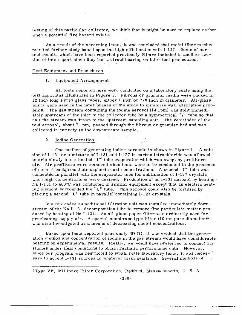
Shock wave cleaning in the 5 foot pilot plant was also tested with 12 gage shotgun blank cartridges (75 grains propellant) on a 400 ton open hearth furnace as shown in Figure 1.
-351-
-352-
Procedure for performing a test on the slag wool filter pilot plant was to start filter gas flow, record temperatures, flow, and color of effluent from fan stack, and sample simultaneously inlet, midpoint, (between agglomerator and filter) and effluent gas streams, stopping tests when gas flow became too low. The filter was then allowed to cool, and resistance of the filter was obtained at room air temperature. A singlf! (or multiple) 12 gage shotgun blast was used to clean the filter, then its resistahce was obtained again, after allowing the dislodged cloud to settle onto a wa.ier surface. Two tests were performed with "continuous 11 on-stream cleaning (without waiting to allow dislodged dust to settle) to evaluate settling on-stream as a direct approach to dislodged fume dis -posal. In these cases, one operator stood on top of the unit and fired a shell upon request from the test data recorder (Figure 1 ).
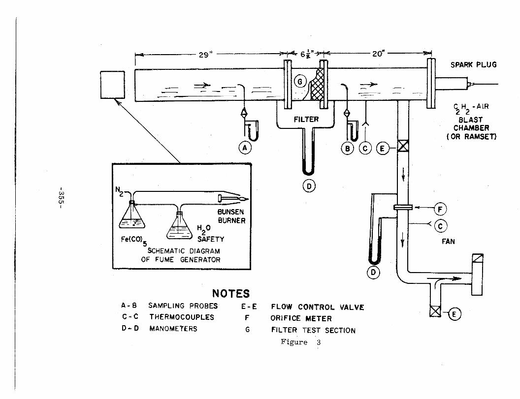
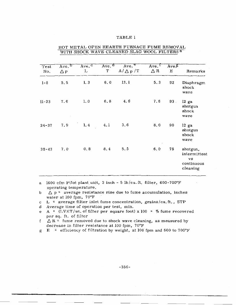
Forty-three tests were run on four separate filters with results as indicated in Table 1. Three filters were cleaned from 8 to 14 times before efficiency decreased to below 80%, when a new filter layer was installed. The last tests (38-43) were used to evaluate intermittent and continuous on-stream· cleaning. These latter data are plotted in summary form in Figure 2. Tests with continuous onstream cleaning (38 and 40) have higher resistance than those in which the filter compartment was shut off from the suction source before blasting (a 1. 5 minute period was allowed for blasted dust to settle). Results from this test series indicated that the slag wool filter could be cleaned from 10 to 15 times; however, fiber attrition resulted from blast wave action, causing the efficiency to decrease to 80%. We established that shock waves from small explosions could remove accumulated fine fume deposits from a deep filter. To withstand the repeated shocks a less fragile (more flexible and resilient) blast resistant media was required for continuous operation. A laboratory study of various refractory wools and other media was initiated.
HIGH TEMPERATURE FILTER MEDIA SCREENING TESTS
Our initial studies on high temperature fume filtration involved the concept which used inexpensive (1 cent per pound) slag wool as a ,replaceable filter media. Since periodic replacement included cost and complex considerations in design of a final filter unit, a comprehensive study of permanent media capable of being shock wave cleaned in place was undertaken.
Several filter materials were evaluated with respect to air flow-resistance characteristics, filtration efficiency for fine iron oxide fume, temperature stability, and blast wave resistance.
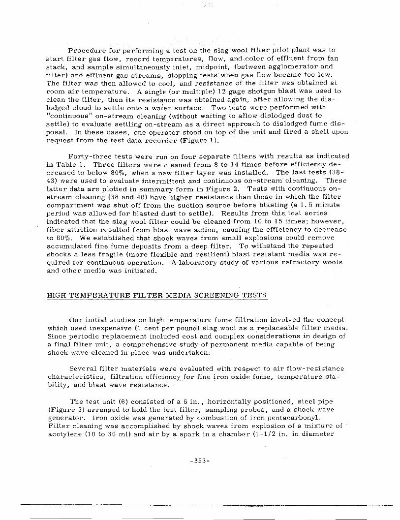
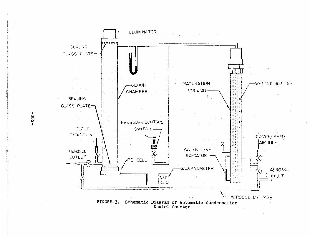
The test unit (6) consisted of a 6 in., horizontally positioned, steel pipe (Figure 3) arranged to hold the test filter, sampling probes, and a shock wave generator. Iron oxide was generated by combustion of iron pentacarbonyl. Filter cleaning was accomplished by shock waves from explosion of a mixture of acetylene (10 to 30 ml) and air by a spark in a chamber (1-1 /2 in. in diameter
-353-
18
17
16
15
~ 14 w ~ 13 ~ LL 12 o 11 (/) w :t: 10 0 :z - 9
IJJ 8 0 z <( 7 t-(/)
(/) 6 LL.I a::
5 a::
~ 4
LL 3
2
38 ( 0.25' CJr/cu. ft., st.)
41 (0.20)
_____ ..
ING 1.5 MINUTE QUIESCENT ERIOD FOR DISLODGED FUME TO SETTLE ONTO
WATE SURFACE 12.IN. BELOW FILTE )
42 (>I est.)
. .. ~9(0.05
0 CONTINUOUS EANING WITH 12 A• BLANK CARTRIOG£ (f)
CLEANED ON Y AT END OF TEST
O O 2 3 4 5 6 7 8 9 I 0 11 12 13 14 Figure 2 OPERATING TIME (MINUTES)
HOT METAL OPEN HEARTH FURNACE FUME REMOVAL WITH SHOCK WAVE CLEANED SLAG WOOL FILTERS a
Test Ave.b Ave.c Ave.a Ave. e Ave. f Ave.g No. D. p L T A/.6p/T .6R E
1-8 5.5 1. 3 6.0 13. 1 5.3 92
11-23 7.6 1. 0 6.8 4.6 7.6 93.
24-37 7. 9 1. 4 4.1 3.6 8.0 90
38-43 7.0 0.8 8.4 5.5 6.0 78
a 1600 cfm Pilot plant unit, 2 inch - 5 lb /cu. ft. filter, 600-700°F operating temperature.
Remarks
Diaphragm shock wave
12 ga shotgun shock wave
12 ga shotgun shock wave
shotgun, intermittent
vs continuous cleaning
b 6. p = average resistance rise due to fume accumulation, inches water at 100 fpm, 70°F
c L = average filter inlet fume concentration, grains/cu. ft., STP d Average time of operation per test, min. e A = (LVET /wt. of filter per square foot) x 100 = % fume recovered
per sq. ft. of filter f 6. R = fume removed due to shock wave cleaning, as measured by
decrease in filter resistance at 100 fpm, 70°F g E = efficiency of filtration by weight, at 100 fpm and 600 to 700°F
-356-
and 4 in. in length). From previous tests it was demonstrated that a distance of 20 in. between the filter and the opening of the blast chamber produced shock waves of sufficient intensity to clean the filter adequately.
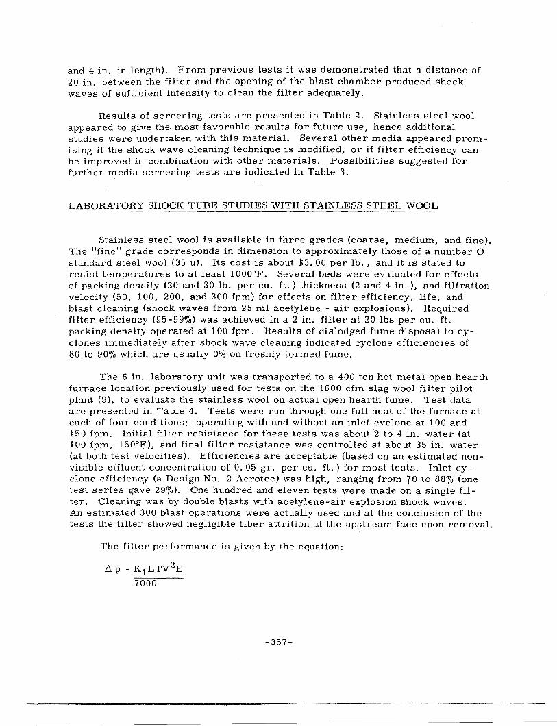
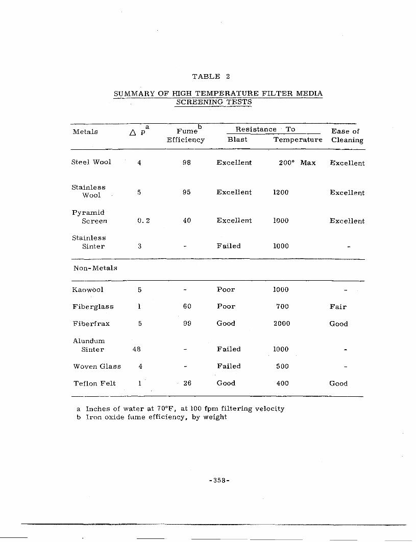
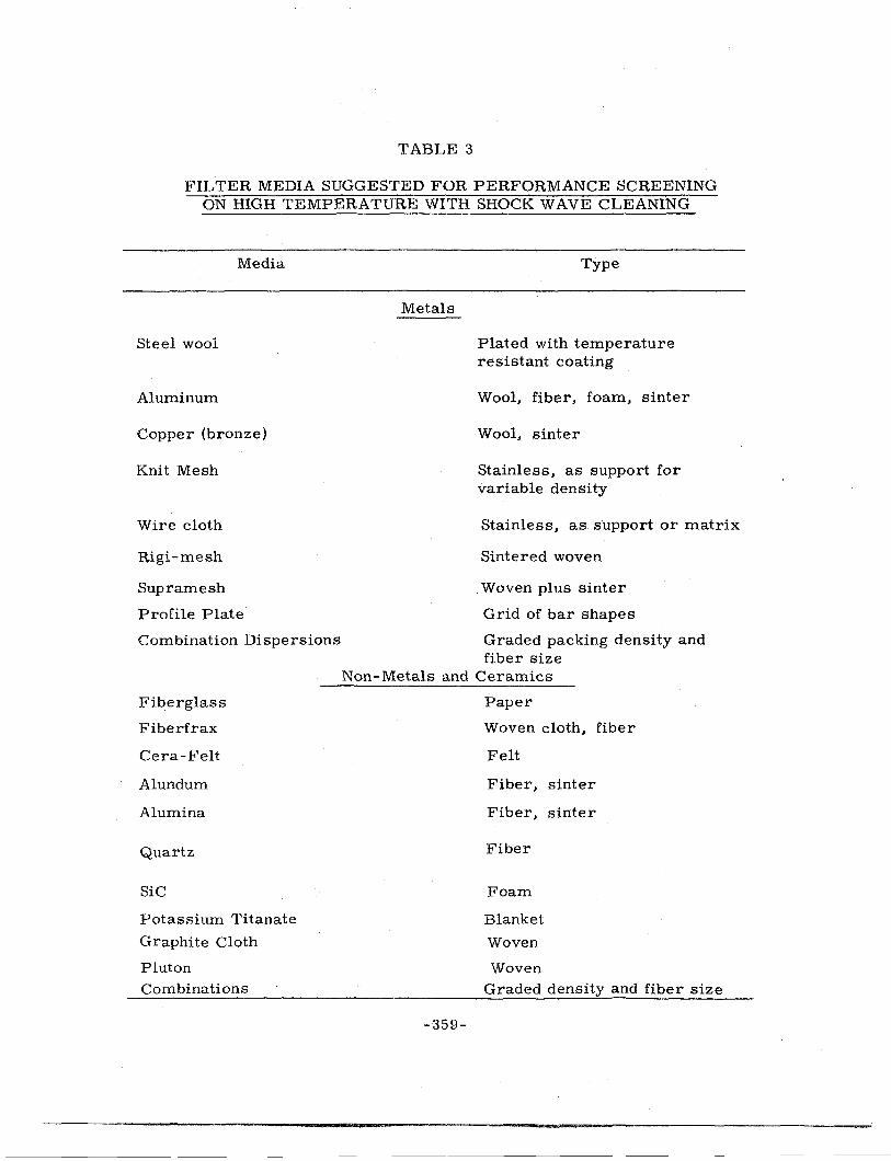
Results of screening tests are presented in Table 2. Stainless steel wool appeared to give th~ most favorable results for future use, hence additional studies were undertaken with this material. Several other media appeared promising if the shock wave cleaning technique is modified, or if filter efficiency can be improved in combination with other materials. Possibilities suggested for further media screening tests are indicated in Table 3.
LABO RA TORY SHOCK TUBE STUDIES WITH STAINLESS STEEL WOOL
Stainless steel wool is available in three grades (coarse, medium, and fine). The "fine" grade corresponds in dimension to approximately those of a number O standard steel wool (35 u). Its cost is about $3. 00 per lb., and it is stated to resist temperatures to at least 1000°F. Several beds were evaluated for effects of packing density (20 and 30 lb. per cu. ft.) thickness (2 and 4 in. ), and filtration velocity (50, 100, 200, and 300 fpm) for effects on filter efficiency, life, and blast cleaning (shock waves from 25 ml acetylene - air explosions). Required filter efficiency (95-99%) was achieved in a 2 in. filter at 20 lbs per cu. ft. packing density operated at 100 fpm. Results of dislodged fume disposal to cyclones immediately after shock wave cleaning indicated cyclone efficiencies of 80 to 90% which are usually Oo/o on freshly formed fume.
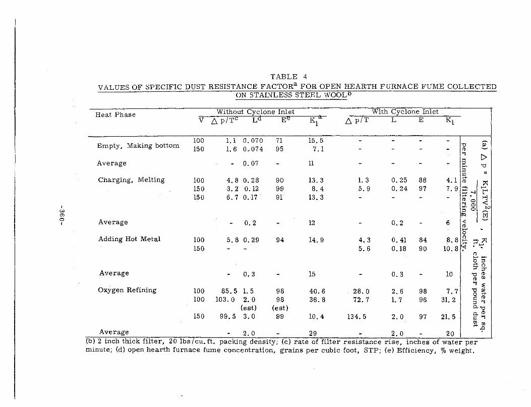
The 6 in. laboratory unit was transported to a 400 ton hot metal open hearth furnace location previously used for tests on the 1600 cfm slag wool filter pilot plant (9), to evaluate the stainless wool on actual open hearth fume. Test data are presented in Table 4. Tests were run through one full heat of the furnace at each of four conditions: operating with and without an inlet cyclone at 100 and 150 fpm. Initial filter resistance for these tests was about 2 to 4 in. water (at 100 fpm, 150°F), and final filter resistance was controlled at about 35 in. water (at both test velocities). Efficiencies are acceptable (based on an estimated nonvisible effluent concentration of 0. 05 gr. per cu. ft.) for most tests. Inlet cyclone efficiency (a Design No. 2 Aerotec) was high, ranging from 70 to 88% (one test series gave 29%). One hundred and eleven tests were made on a single filter. Cleaning was by double blasts with acetylene-air explosion shock waves. An estimated 300 blast operations were actually used and at the conclusion of the tests the filter showed negligible fiber attrition at the upstream face upon removal.
The filter performance is given by the equation:
-357-
TABLE 2
SUMMARY OF HIGH TEMPERATURE FILTER MEDIA SCREENING TESTS
Metals
Steel Wool
Stainless Wool
a D. p
4
5
Pyramid Screen 0.2
Stainless Sinter
Non-Metals
Kaowool
Fiberglass
Fiberfrax
Alundum
3
5
1
5
Sinter 48
Woven Glass 4
Teflon Felt 1
b Fume
Efficiency
98
95
40
60
99
26
Resistance To
Blast Temperature
Excellent 200° Max
Excellent 1200
Excellent 1000
Failed 1000
Poor 1000
Poor 700
Good 2000
Failed 1000
Failed 500
Good 400
a Inches of water at 70°F. at 100 fpm filtering velocity b Iron oxide fume efficiency, by weight
-358-
Ease of Cleaning
Excellent
Excellent
Excellent
Fair
Good
Good
TABLE 3
FILTER MEDIA SUGGESTED FOR PERFORMANCE SCREENING ON HIGH TEMPERATURE WITH SHOCK WAVE CLEANING
Media Type
Metals
Steel wool Plated with temperature resistant coating
Aluminum Wool, fiber, foam, sinter
Copper (bronze) Wool, sinter
Knit Mesh Stainless, as support for variable density
Wire cloth Stainless, as. support or matrix
Rigi-mesh Sintered woven
Supramesh Woven plus sinter
Profile Plate Grid of bar shapes
Combination Dispersions Graded packing density and fiber size
Non- Metals and Ceramics
Fiberglass Paper
Fiberfrax Woven cloth, fiber
Cera-Felt Felt
Alundum Fiber, sinter
Alumina Fiber, sinter
Quartz Fiber
filC Foom
Potassium Titanate Blanket
Graphite Cloth Woven
Pluton Woven Combinations Graded density and fiber size
-359-
TABLE 4
VALUES OF SPECIFIC DUST RESISTANCE FACTORa FOR OPEN HEARTH FURNACE FUME COLLECTED ON STAINLESS STEEL WOOL 5
Heat Phase Without Cyclone Inlet With Cyclone Inlet v f::::. p/TC O'i Ee Ka: !::::. p/T L E K1 1
Average - 2.0 - 29 - 2.0 - 20 (b) 2 inch thick filter, 20 lbs/cu. ft. packing density; (c) rate of filter resistance rise, inches of water per minute; (d) open hearth furnace fume concentration, grains per cubic foot, STP; (e) Efficiency, % weight.
We believe there are variations in K1 with both dust loading and velocity which are unknown at present. Values of K1 for 100 and 150 fpm with and without cyclone inlet are shown for each major phase of furnace operation. K1 ranges from 4 to 11 for operations other than oxygen blowing, with the cyclone in the inlet to the filter, and ranges from 7 to 15 with no cyclone in the inlet. With oxygen refining K
1 ranges from 8 to 30 approximately, with cyclone inlet, and from 10 to 40 with
out cyclone inlet. The K1 values are generally higher when oxygen is used, and are presumably independent of dust concentration (although this actually may not be true), This may indicate a significant change in fume particle size (smaller) during oxygen operation. Dust loadings are much higher (5 to 10 times) for oxygen refining.
Values of K 1 (specific dust resistance) for other dusts on ordinary bag collectors have been reported (10)(11 ). Values of Ki for fine fumes on cotton sateen bags are: titanium dioxide from 100 to 200 (being about 1 /3 of these on wool, a "deep bed" filter); freshly formed MgO, 240; tobacco (dust?) and carbon black (redispersed) 25 to 35 respectfvely; and 4 7 for lamp black. Data on these dusts was reported for filter velocities of 1 to 2 cfm I sq. ft. The values reported in Table 4 indicate that substantially greater amounts of fume may be held in a deep bed during filter surface, even with a 100 to 1 increase in filtration velocity.
STAINLESS STEEL WOOL FILTER PILOT PLANT STUDY
A 400 cfm pilot plant unit has been constructed for laboratory and field testing of stainless steel wool filters for high temperature furnace effluents. It includes automatic shock wave generation by propellant cartridge for on-stream cleaning, and contains a dynamic dislodged fume disposal system of a 64 tube (2 in. diam.) axial cyclonic collector positioned just below the filter bed (1-1 /2 in.) as shown in Figure 4.
The unit is constructed from H. R. S. channels in the shape of a box 28 in. square. A stainless steel wool filter is contained in a 6 in. channel box between two screens adjustable for bed thicknesses of 1 to 6 in. Effective bed area is 4 sq. ft. (2' x 2' ). It is fastened to the axial cyclonic dislodged fume collector (Farr Co. - Rotonamic, Model-R24) by means of extension flanges welded to the collector box.
The unit represents a modular prototype for one-cell of a multicell filter unit. It will be self-contained to have all features necessary for continuous automatic operation and represents a collection unit analogous to one bag of a bag house, or one cyclone tube of a multicell cyclone unit. Development of a full scale collection unit for particular application should require only multiplication of this basic unit to achieve an operational design of sufficient size to be suitable for the desired gas flow at the operational temperature, i.e., 50, 000 cfm would theoretically require 125 of these units, in whatever geometric arrangement seems best for the space available at a given installation.
TO AUXILIARY BLEED STREAM FAN (40 cfm) (RETURN TO INLET)
(SECONDARY FOR DISLODGED 4 FUME DISPOSAL)
This unit has been installed as indicated in Figure 4 for laboratory tests on jet-redispersed reagent iron oxide powder (1 u). Sampling probes are installed (a) in the inlet duct, (b) between the axial cyclonic dislodged dust collector and the filter bed, and (c) in the outlet duct, as shown. Resistance of the clean filter media (installed) is given by: d p (in. water) = 0. 0091 V (fpm filtering velocity), and the cyclonic collector by: 4P (in. water)= 3. 7 x 10⁻⁶ Q2 (cfm).
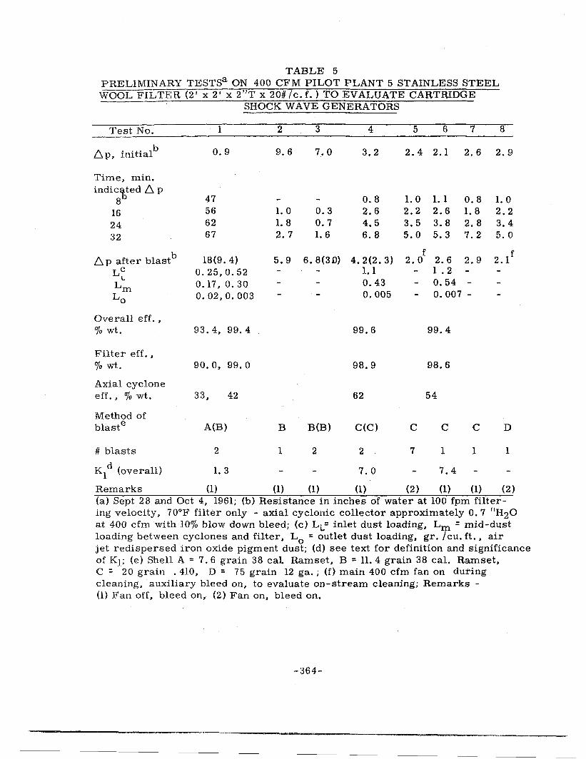
In order to evaluate cartridge shock wave generation methods, the unit was operated eight times with air-jet redispersed fine iron oxide powder, and cleaned with various test cartridge loadings. Results of these tests are presented in Table 5.
The effect of powder charge (shell loading, grains I sq. ft. filter area) on filter cleaning as determined from these tests is:
1. Main air flow off (auxiliary air on) 11 R ~ 17 (Powder charge, gr. I sq. ft. )
1 /
3
2. Main air flow on (auxiliary air on)
ll R '= 11. 4 (Powder charge, gr. /sq. ft. )1/ 3
The shock wave is about 30% less effective when main air flow is continued during cleaning, as indicated by the lower equation constant.
Filter efficiency was at all times acceptable, the outlet concentration being below visibility limits ( < 0. 05 gr. per cu. ft.).
Values of K 1 compare favorably with those cited above for stainless steel wool tests in the 6 in. laboratory prepilot unit. The axial cyclonic collector is apparently operating satisfactorily, as judged by amount of dislodged dust recovered from the auxiliary bleed stream cyclone.
DISLODGED FUME DISPOSAL STUDY
Performance of a two-tube axial cyclone in our 6 in. laboratory filter test unit is presented in Table 6 on carbonyl generated and air jet-redispersed iron oxide test aerosol.
Use of the axial cyclonic collector below fine stainless steel wool filter beds to capture shock wave dislodged fume agglomerates during on-stream filter operation is described above. Operation of this combination is indicated in Figure 4, fume entering the normal exit tube (with respect to the manufacturer's designed direction of flow) of the cyclonic device. As the shock wave passes through the filter bed, deposited fume is dislodged and projected into the cyclone in the normal (intended) direction. A continuous bleed stream (10% of full unit flow) is withdrawn
-363-
TABLE 5 PRELIMINARY TESTSa ON 400 CFM PILOT PLANT 5 STAINLESS STEEL WOOL FILTER (2' x 2' x 2"T x 20#/c.f.) TO EVALUATE CARTRIDGE
SHOCK WAVE GENERA TORS
Test No.
I\ . 't' lb up, 1n1 1a
Time, min. indicited 6 p
8 16 24 32
b 6. p after blast Lc
L
Lm Lo
Overall eff., % wt.
Filter eff., % wt.
Axial cyclone eff., % wt.
Method of blaste
# blasts
d K1
(overall)
1
0.9
47 56 62 67
18(9. 4) 0.25,0.52 0.17. o. 30 0.02,0.003
93.4, 99.4
90. o. 99. 0
33, 42
A(B)
2
1. 3
2
9.6
1. 0 1. 8 2. 7
5.9
B
1
3
7.0
0.3 0.7 1. 6
4
3.2
0.8 2.6 4.5 6.8
6. 8(30) 4. 2(2. 3) 1.1 0.43 0.005
B(B)
2
99.6
98.9
62
C(C)
2
7.0
5 6 7 8
2.4 2.1 2.6 2.9
1.0 1.1 2.2 2.6 3.5 3.8 5.0 5.3
o. 8 1. 0 1.8 2.2 2. 8 3. 4 7. 2 5. 0
f 2.0 2.6 2.9
c
7
l . 2 o. 54 -o. 007 -
99.4
98.6
54
c c
1 1
7.4
D
1
Remarks (1) (1) (1) (1) (2) (1) (1) (2) (a) Sept 28 and Oct 4, 1961; (b) Resistance in inches of water at 100 fpm filtering velocity, 7 0°F filter only - axial cyclonic collector approximately 0. 7 "H20 at 400 cfm with 10% blow down bleed; (c) LL= inlet dust loading, Lm = mid-dust loading between cyclones and filter, L
0 = outlet dust loading, gr. I cu. ft. , air
jet redispersed iron oxide pigment dust; (d) see text for definition and significance of K1; (e) Shell A = 7. 6 grain 38 cal Ramset, B = 11. 4 grain 38 cal. Ramset, C = 20 grain . 410, D = 75 grain 12 ga.; (f) main 400 cfm fan on during cleaning, auxiliary bleed on, to evaluate on-stream cleaning; Remarks -(1) Fan off, bleed on, (2) Fan on, bleed on.
-364-
TABLE 6 IRON OXIDE FUME EFFICIENCY AND RESISTANCE OF FARR COMPANY
"ROTONAMIC" (2-24) AXIAL CYCLONIC COLLECTOR
Test Loading Loading Efficiency Resistance No. Up-stream downstream Percent Initial Final Remarks
from the base of the Rotonamic unit and directed to an auxiliary collector system (an impinger operated at 2 cfm for these laboratory studies), and the dislodged fume is thus dynamically removed from the filter and discharged from the main unit in a small air volume, without halting primary air flow.
During combined filter and cyclone tests, it was not possible to separate cyclonic unit air flow resistance or iron oxide fume efficiency from that obtained from the filter, due to the very close (1 in.) spacing of the cyclone and filter.
Performance of a 2-tube cyclonic unit without the stainless steel wool filter in place has been determined. The cyclone was tested with air flow both in the direction we normally used it (reverse flow by manufacturer) and in the intended direction on iron pentacarbonyl-generated fume, and on air-jet redispersed technical grade Fe203. Main flow through the collector was 20 cfm, or 10 cfm per tube of the 2-tube Rotonamic collector which is 66% of the manufacturer's rating for the device. Samples were drawn isokinetically up and downstream of the device and analyzed gravimetrically.
With submicron fume at low loadings (tests 1-6 and 22-26) removal efficiency is essentially zero regardless of flow direction, and resistance to gas flow stays constant at about 3. 5 in. of water. Use of redispersed iron oxide powder at a moderate loading with the collector operated as intended (tests 12-16) yielded an average efficiency of 41 %. No plugging or gradual increase in base resistance of the cyclone unit was observed at this loading on this particle size. Upon increasing the loading by about an order of magnitude (collector op_erated in its normal intended direction) the efficiency increased to about 52% (average) (tests 17-21). Considerable plugging was observed at these loadings. Tests at high loading with collector reversed (the way we are currently using it in the filter unit) (tests 7-11) indicate an average (redispersed iron oxide) fume removal efficiency of 52%, or the same as was observed when operated in normal direction. More significant amounts of plugging were observed with the unit operated in the reverse direction.
High dust loadings apparently tend to plug tubes and vanes, and this can be reduced or eliminated by increasing bleed air volume. The highest bleed volume (30%) produced constant resistance in the device.
Other tests are planned to evaluate efficiency, resistance, and plugging problems with high loadings at 40 cfm per tube (266% of recommended flow).
CONCLUSIONS
1. Stainless steel wool filters 2 in. thick and 20 to 30 lbs per cu. ft. packing density will effectively filter hot metal open hearth furnace fume at 100 and 150 fpm. Effluent concentrations from the filter are considered essentially nonvisibie, based on an assumed concentration of about 0. 05 gr. per cu. ft.
-366-
2. Deep bed stainless steel wool filters apparently hold 5 to 20 times as much collected fume as do standard bag collectors (per unit resistance increase), even when the stainless wool filter is operated at 100 times the filtering velocity usually employed in cloth bag collectors.
3. Use of diaphragm, cartridge, or gas-air explosive generated shock waves for deep bed filter cleaning can restore filter operating resistance to essentially clean values.
4. Dislodged fume disposal studies have indicated that although the material will settle out of a quiescent gas in a few minutes, it can be removed from an entraining air stream at 70 to 90% efficiency with small diameter cyclones. Dislodged material has been demonstrated to be considerably agglomerated (8).
5. On-stream cleaning has been developed to eliminate the need to bypass the total air flow during cleaning.
6. Other refractory filter media can also be utilized for high temperature gas cleaning problems. Of the several already evaluated, plated or treated steel wool, aluminum, and certain ceramic materials appear to offer significant possibilities.
7. Shock wave generation methods used during these studies have been restricted to rupture diaphragm explosive, cartridge, and explosive gas-air mixtures. Other methods have been proposed and are under consideration.
ACKNOWLEDGEMENTS
We acknowledge with appreciation the assistance of L. H. Levenbaum, T. W. Baldwin, and our colleagues at the Harvard Air Cleaning Laboratory who obtained much of the test data. The American Iron and Steel Institute supported these studies through its Subcommittee on Air Pollution Abatement. Dr. A. D. Brandt, Mr. G. S. Reichenbach, Jr., and the Bethlehem Steel Company (Sparrows Point, Maryland) operations personnel cooperated in the successful field studies reported here. Cartridges and firearms used in field and laboratory investigations were supplied through the courtesy of Winchester-Western Division of OlinMathieson Chemical Company, New Haven, Connecticut. Mr. E. Lowry and his group provided thousands of trial explosives for our use.
-367-
REFERENCES
1. Hersey, H. T., Jr., New Developments in Reverse-Jet Filters, AIHA Quart., 14:3 (September 1953).
3. Billings, C. E., Dennis, R., and Silverman, L., Blast Damage to Air Cleaning Devices (Filter Tests}, USAEC, NY0-1595, Harvard University (November 1955).
4. Billings, C. E., Dennis, R. and Silverman, L., Blast Effects on Air Cleaning Equipment - Results of Filter Tests. Fourth AEC Air Cleaning Conference, TID-7513 (Pt. 1), (June 1956).
5. Dennis, R. and Billings, C. E., Blast Effects on an Air Cleaning System. USAEC, Operation Plumbbob Preliminary Report, CETG Proj. 34. 4, ITR-1475, (November 1957).
6. Levenbaum, L. H., Billings, C. E., Malani, N., Dennis, R., and Silverman, L., Progress Report on Harvard-American Iron and Steel Institute Research Project. Sixth AEC Air Cleaning Conference, TID-7593, (October 1960).
7. Dennis, R., Silverman, L., Kristal, E., Anderson, D. M., Billings, C. E., Stein, F., and Drinker, P., Air Cleaning Studies - Progress Report for July 1, 1957 to June 30, 1958. USAEC, NY0-4812, Harvard University (March 1961 ).
8. Billings, C. E., Silverman, L., Dennis, R., and Levenbaum, L., Shock Wave Cleaning of Air Filters, J APCA, .!._Q:318 (1960).
9. Billings, C. E. and Silverman, L., High Temperature Filter Media Performance With Shock Wave Cleaning. Presented at 1961 Annual Meeting of the American Industrial Hygiene Association, April 10-13, 1961, Detroit, Mich.
10. Billings, C. E., Gussman, R. A., Levenbaum, L. H., Baldwin, T. W., and Silverman, L., Open Hearth Stack Gas Cleaning Studies, Semi-Annual Progress Report (SA-14) for May 1, 1960 to October 31, 1960, Harvard University (November 1961 ).
11. Unpublished data.
-368-
DISCUSSION
HAYS: I have a question for Mr. Dennis on his review. The slide where you showed the inlet concentration effect on silver plate. Do you see the same effect on activated carbon beds?
DENNIS: We have essentially the same type of curve, that is, it decreases linearly on a semi-log plot with slight tailing off. The big difference is that the carbon, to the best of our knowledge (here we are using carbon as the absolute) is retaining approximately 100 per cent of the iodine. In the case of the copper, we are only retaining 90 to 95 percent of the total iodine, this is based upon the residual material collected in our downstream sample.
MACFARLANE: You mentioned the importance of surface preparation of your copper. Does the method of plating vary?
DENNIS: Our media was electroplated by conventional means. We sent the material to a local plating outfit and told them to silverplate it. We found no variance in the end products. Chalk River ran several treatments on a different type of copper mesh and found that the nature of the surface made a big difference in their results. However, they used different techniques in sampling. It is hard to tell whether the difference in performance is due to the copper or metal surface or to the sampling or aerosol generation method.
SIL VER MAN: I would add one point. Rochelle salt plating, or mirroring. chemical plate as with electroplated
We did plate glass and slag fibers with We found the same performance on
silver.
DENNIS: I would like to make this comment in reply to a question I answered this morning. When we evaluated the silver plated copper and took our gas temperatures up to 3oooc, we observed better performance than we had at room temperature. When we allowed the bed to cool down to room temperature, the silver oxide surface became. a poor collector at room temperature. When we elevated bed temperature again to 300°C, efficiency returned to the 99. 9 range. If a silver plated bed is once exposed to high temperature, it will be necessary to keep it at that temperature to guarantee effective service.
GEMMELL: It was my impression fron1 one of the papers this morning that it never did regain it. Is that right?
-369-
SILVERMAN: That was the understanding I had for room temperature collection.
GEMMELL: According to your data it does regain its efficiency. Is that correct?
DENNIS: Yes. This is based on 100 hours of operation, during which period the difference in efficiency was noted. We are not, however, talking about performance with the low order iodine concentrations most likely to occur in current field problems.
ADAMS: I didn't mean to leave the impression this morning that this silver plated copper did not regain its efficiency at elevated temperatures. I concur with Mr. Dennis' findings.
UNKNOWN: I would add one thing: I think Mr. Billings didn't mean to say that we adjusted this blowback system on the actual cyclones. We have run a large number of tests on the six-inch units and then scaled up.
This 400 CFM pilot plant, with sixty-four of these little fellows, is agreeing with our - - we have two in the six-inch bed that are acting in reverse to pass air through the exit pipe and then we blast, we force the heavy load to go through the cyclone in its normal direction during the shock wave and this is going to, if it coptinues to behave like we hope it does, is going to give us the opportunity to clean onstream continuously. We have tried blasting onstream continuously where we took the blasted material off through a cyclone externally to the system and this worked pretty well, but by being able to clean the bed, just as a water hammer goes down a pipe one way while the water is going the other way, we hope we can keep the resistance within a certain range.
SHAPIRO: In relation to the last comment, it might be of interest to know that we have been using a similar system in our feed materials plant for blowing back porous metal filters onstream which we do with a stream of air impulsed through a solenoid valve for a relatively short duration. We have been able to keep these filters onstream during normal operations with considerably high dust loading.
We have been doing this entirely by air pressure.
SILVERMAN: With what do you collect the dislodged material?
SHAPIRO: We knock it down into a hopper. We were unable to get satisfactory results when we had cyclones in the line. We apparently entrained enough fine materials and impacted them on the porous filter material so that our filter life was very short. We removed the cyclone and went to the straight blowback system and the system functions perfectly now.
SILVERMAN: Our original experience with pilot plant 4, the circular one Mr. Billings showed on the slide, was that we had to allow sufficient time
-370-
for the material to settle, otherwise it returned to the filter surface and we were in the same state before we blew it off. Unless we take the dust or fume out of the gas stream, re-entrainment and redeposition becomes a problem.
Our agglomerates are relatively small -- the glomerates are 0. 2 to 0. 3 u. If we catch them right away they are much larger, otherwise we couldn't explain the highly efficient cyclone performance. They are not tightly held agglomerates, however, and they can come apart easily.
SCHWENDIMAN: What is the efficiency of the cyclone? Do you have to have a filter on the end of the cyclone?
SILVERMAN: This is best explained by saying we get back onto the same filter. We get 70 to 90 percent on the cyclone and then its effluent, from the bypass flow is returned to the main filter. It is perpetual motion, but not quite.
BILLINGS: With respect to iodine on copper mesh, how much bed length did you extend this to on the theory that it should get better and better the longer you go?
DENNIS: At one foot per second velocity, with a four inch deep bed, the linear portion of the retention curve ended at approximately two to two and a half inches bed depth. At that point the theoretical residual amounted to 0. 1 - 0. 01 percent of the iodine retained in the first two and a half inches.
We tried the obvious, i.e., doubling the length of the bed which, in theory, should increase efficiency, when collecting a homogeneous material. However, we observed precisely the same collection that we had before. It appears that the iodine phase not immediately collectable would not be recovered by merely increasing bed depth.
CHEEVER: What is the charcoal mesh size that gives the highest decontamination factor at a given pressure drop?
DENNIS: We have not investigated charcoal from that point of view. There is much information in the literature now indicating that carbon is a good collector in the size range of 8 to 14 mesh and 6 to 12. mesh which applies to the carbons tested in our laboratory.
We have not made any attempt to correlate efficiency with granule size.
-371-
FACTORS IN CONDENSATION NUCLEI COUNTERS FOR MEASUREMENT OF AEROSOL AGGLOMERATION
Robert A. Gussman, Charles E. Billings, and Leslie Silverman Harvard School of Public Health
ABSTRACT
Industrial and nuclear energy processes produce air-borne suspensions of ultra-fine aerosols in effluents from metallurgical reduction furnaces, combustion and vaporization reactions of all kinds, and various reactor concepts. Economical gas cleaning devices for particles in the sub-micron range may be achieved by causing particles to grow by induced collision and agglomeration. This may be accomplished by utilizing various forces. Measurement of such agglomeration depends upon a knowledge of the number concentration of particles at successive times in a dynamic gas flow system. This paper presents some suggested methods for producing aerosol agglomeration in flowing gas streams; an outline of requirements for a continuous particle number concentration instrument to be used for assessing dynamic agglomeration; and a brief discussion of condensation nuclei counters for measuring aerosols. Since condensation nuclei can be grown in a supersaturated atmosphere to droplets of a homogeneous size, uses of this phenomena for dynamic particle concentration measurements on sub-micron particles are discussed. Diluter systems are described for the reduction of concentrations found in industrial aerosols (106-1011 p/ml) to levels useable in aerosol counters (1 o5 p/ml).
INTRODUCTION
Economic elimination of visible effluents from high temperature metallurgical furnaces is a major need in air pollution control. Such fumes are sub-micron in size and in the newer oxygen blown steel production operations concentrations greater than 2 gr/cu. ft. are commonly encountered. In industrial gas cleaning systems, agglomeration takes place .between the point at which the particulates are formed and entrained in an air stream, and any given point downstream. Devices such as waste heat boilers or filtering apparatus produce significant agglomeration. Particles in an aerosol collide due to Brownian motion and adhere, forming chains or lattices (called agglomerates). Other forces causing agglomeration present in dynamic systems are turbulence, electrostatic charge, and thermal convection. Specific external forces such as from electrical, magnetic, or sonic fields can be used. Increased agglomeration increases particle size and can improve the performance of inertial collectors or filtration devices. We have described methods for inducing significant agglomeration in furnace fume and have demonstrated by mechanical agglomeration devices (Silverman-A) increased filter life on open hearth furnace fume.
-372-
Methods to measure agglomeration (other than effects on filter life) are needed for rapid measurements in order to evaluate proposed studies involving external forces. Measurement of agglomeration in a dynamic system requires knowledge of the number concentration of particles at successive times and locations. The instrument needed for these evaluations should determine particle numbers without inducing or influencing agglomeration.
This paper describes development, operation and calibration of a particle concentration measuring instrument to be used for assessing dynamic agglomeration. Aerosols under study are used as condensation nuclei which grow in a supersaturated atmosphere to homogeneous size. Diluter systems to reduce particle con -centrations found in industrial stacks (1010 particles per 1 ml.) to within a range useable in counters (105) are essential. Possible errors and interferences in this device are also considered.
Agglomeration
A. Natural Agglomeration
When two particles suspended in a gas collide because of their random thermal (Brownian) motion, they generally adhere due to inter-particle forces to form one larger particle. The time rate of reduction of number concentration is given as:
where:
- dn = Kn2 dt
k = coagulation constant (approximately 3 x 10-lO ml/sec)
n = number of particles per ml. t = time, sec.
(1)
Coagulation of a homogeneous aerosol due to Brownian motion is theoretically independent of particle size up to about 1 or 2 microns, and depends only on particle concentration as indicated in Table 1. As the aerosol coagulates, it becomes heterogeneous and a new equation becomes necessary. Coagulation is more rapid for a heterogeneous aerosol such that coagulation of particles with sizes over a range of 1 to 8 occurs about 25% more rapidly. The theoretical rate equation (1) is modified for particles less than about 0. 5 u diameter; for heterogenity of particle size; and also for effects due to turbulence and other forces. The coagulation coefficient may be determined by measuring particle number concentration as a function of time.
B. Forces Applied to Increase Agglomeration
The following potential mechanisms are being considered for increasing the agglomeration rate of fine open hearth furnace fume (Silverman-A).
-373-
TABLE 1
Rate Of Coagulation Required To Reduce Number Of Particles To One Tenth Initial Number
No. per ml t 0 , sec.
1014 0.0003
1013 0.003
1012 0.03
1011 0.3
1010 3
109 30
108 300
107 3000
TABLE 2
Instrument Criteria for Measurement Of Agglomeration of Aerosol Particles
1. Dilution of industrial concentrations by several orders of magnitude
2. Continuous operation with instantaneous readout
3. Independent of initial size of aerosol particles
4. Independent of composition of aerosol particles or gases present
5. Independent of particles below a specified size
6. Charge effects negligible for particles of concern
-374-
1. Mechanical and thermal agitation 2. Deposition and Reentrainment 3. Use of auxiliary forces
a. Magnetic b. Electrostatic c. Sonic
4. Use of added aerosols a. Water sprays b. Steam c. Recycled aerosols d. Different particle shapes
5. Use of moving targets such as steel shot or extended surface packings to induce turbulence, deposition and reent rainment
We have demonstrated significant increases in the size of iron oxide fume particles deposited on filter fibers and reentrained by blast wave cleaning (Billings.,..B). Dislodged fumes can be collected in a small radius cyclone at greater than 80% efficiency, as compared to nothing retained on the freshly formed fume concentration. Other studies have shown large particle size after the gas passes waste heat boilers due to turbulence, thermal and inertial deposition and reentrainment (Silverman-B).
Our efforts to date have used the first mechanism (mechanical and thermal agitation) in a conveyor screw placed in a cylindrical chamber with tangential entry. This device is a primary inertial mechanical collector comparable to a small radius cyclone (inlet velocities of 400 feet per minute are utilized). It presents a long turbulent path providing contact time for the aerosol, and also increased surfaces for collision. The cooling effect provides a gradient for thermal precipitation and subsequent reentrainment produced by rotating the screw occasionally.
Future studies will include development of simple systems using mechanisms delineated above to produce agglomeration and increased fume particle size. Evaluation of various systems depends upon the development of a simple rapid field type instrument to yield information on the rate of change of number concentration in a flowing aerosol.
Instruments for the Measurement of Agglomeration
A. Criteria for an Instrument to Measure Agglomeration
Because of the tenuous nature of agglomerates formed in aerosols, the aggregates should be counted in vivo with minimal disrupting forces applied during measurement. In industrial aerosol systems, particle concentrations may be encountered as high as 1ol0 particles /ml, or higher. An instrument to discriminate and measure at these concentrations presently appears impractical. Some form
-375-
of dilution system will have to be employed to reduce particle concentrations several orders of magnitude, again with minimal disturbing forces applied to the particles. Other criteria desirable in a field-type instrument for measurement of industrial concentrations have been listed in Table 2.
Concentrations should be determined instantaneously (since agglomeration is time dependent) and continuously (to detect changes in agglomeration rate over short time intervals). The device should give particle counts independent of particle size, composition, charge, or contaminants in the carrier gas stream.
B. Visual Method for Assessing Agglomeration
We have measured agglomeration by precipitating samples of the airborne particles on carbon coated electron microscope grids and counting particles from electron photomicrographs. This method does not permit rapid screening of many potential agglomeration mechanisms.
C. Use of Size Dependent Collectors
Other studies have utilized the separation of particles by size to indicate particle growth. Field samples taken with impingers followed by filters on either side of a prototype rotary screw agglomerator indicated improved efficiency for the impinger located downstream of the device; however, substantial de-agglomeration appears to take place in sonic jets (Billings-B).
D. Filter Deposited Layer Porosity
We have also attempted to assess agglomeration by studying the porosity (i.e. air flow resistance) of layers of filtered iron oxide fume, using the Carman-Kozeny concept of porosity variation with particle size. Detectable changes in porosity were slight, and not a reliable index of aggregation state.
E. Particle Counters
There are a few direct optical particle counters, which measure light scattered by individual aerosol particles in vivo as they flow through a carefully defined measuring volume. While these devices give rapid read out of information, cost is of the order of $10, 000, and they are not yet portable enough for field use. They do not resolve particles below about 1I4 micron, and require elaborate dilution systems to reduce particle concentrations. This class of counters has potential for many aerosol problems, but the characterizing of complex agglomerates by this system will probably remain a drawback.
F. Condensation Nuclei Counters
Metallurgical furnace fume effluents contain large numbers of particles less than 1 micron, which is the practical upper size limit of condensation nuclei counters.
-376-
Condensation nuclei counter operation consists of drawing the aerosol (suitably diluted to 1 o5 particles per ml.) into a chamber and allowing it to come to equilibrium with water by means of wetted walls. By, rapidly lowering the pressure (adiabatic expansion), the temperature drops and moisture will condense upon particles present in the gas causing them to grow to the same size (5 to 10 microns) regardless of their initial size (submicron). If a light beam is directed through the chamber onto a photodetector, the grown liquid droplets scatter the light in proportion to their number concentration to reduce the signal at the detector, dependent only upon initial number concentration (independent of the original particle size).
The principle of condensing moisture upon nuclei of all types was first utilized by Aitken in 1888. Green developed an automatic Wilson cloud chamber to allow the droplets formed to be photographed under dark field illumination. Saunders has completely automated the cell so that it can be left unattended during an experiment while recording condensation droplet images on 16 mm movie film at fixed intervals of time. Our recent modification of his device utilizes the Polaroid camera to obtain results immediately and a further change will permit either camera to be operated at will, together with a photomultiplier for electrical readout. These instruments have a useful range of concentrations up to about 106 particles per ml.
In current condensation nuclei counters, adiabatic expansion is achieved by withdrawing a measured amount of air or by increasing chamber volume by withdrawing a piston or bellows at the bottom. The "batch" nature of this type of counter is a drawback, as indicated in our original criteria. We have briefly investigated dynamic condensation counters, in which a saturated aerosol stream is caused to flow through a cold cell and the resulting cloud observed photoelectrically. Various forms of cooling have been employed in the dynamic counter, including dry-ice cooling, Freon refrigerant (in our design the escaping pressurized refrigerant was used simultaneously as the flow inducer, dilution volume, and coolant): and a Hilsch vortex-tube cold source.
Disadvantages of current counters include the batch nature of the process and gaseous interferences in an industrial aerosol, i.e. so2-so3. Disadvantages in the dynamic condensation nuclei counters so far studied center on an inability to control the gas temperature closely at condensation, which governs supersaturation and degree of growth.
Theoretical Design Considerations of Condensation Nuclei Counters
Condensation nuclei consist of small particles of all compositions and ions from various sources. Moisture condensation upon particles is limited by (1) the wettability of surfaces, (2) nuclei size, and (3) ambient vapor pressure.
The upper limit of particle diameter which may be evaluated by condensation techniques is about one micron. The lower limit depends upon the initial supersaturation and is expressed mathematically by the Thompson-Gibbs equation (Green):
-377-
ln P = 2 ~ M -------Pcxi R T fJ r
where: r = radius of.the particle, cm M = molecular weight of the liquid p"' density of the liquid, gm. /cc. ~ ... surface tension of the liquid, dynes I cm.
R = gas constant, ergs /°K/mol T " absolute temperature P vapor pressure surrounding droplets, dynes /cm2
P(j) = vapor pressure over a plane surface, dynes I cm2 P .. supersaturation
PCP
(2)
The curve of this equation is presented in Figure 1, from which the minimum particle size upon which moisture will condense may be obtained for a particular value of supersaturation. If the particles bear an electrical charge, the equation is modified by a charging factor:
= R T ,.o
(3) ln p
p"°
The curve for charged particles is· shown by the dashed line in Figure 1, indicating that the effects of charging become negligible for particles whose radius is greater than 10- 7 cm.
Cooling necessary for the creating of supersaturation is obtained by adiabatically expanding the gas. Temperature change is calculated by the perfect gas laws:
[::] K-1
K
where: K = Cp/Cv.
= (4)
In the "volume defined" expansion method (Saunders-B), the aerosol is contained in a cylinder to which a closely fitting piston is attached and expansion takes place when the piston is sharply withdrawn. In the "pressure defined" system of Pollak and others, the aerosol is contained in a chamber and pressure is raised by the addition of filtered compressed air. Opening of a relief valve allows the chamber to expand back to atmospheric pressure, or the confined aerosol is expanded into a previously evacuated chamber. The volume defined method gives greater supersaturation (temperature drop) than the pressure defined method for equal expansion ratios but the pressure defined method requires only clean air for overpressuring.
-378-
rtja..."' I. 5 ~
0 r ~ u:: Ul 1.4 a:
I ':) w (/) -:i CD I
(/1 Lll er c... 1.3
t.2
I.I
1.0
r- --
I .
ts -- <,;;{
~6 _.)
r <t tn er:
-- 111 ___ c.. :J ({)4
------- --- -·· 2~M (£..)= RTfr Ln P-
10-8 10-7 10-6 10- 5
RADIUS , CM.
FIGURE 1. Supersaturation and Expansion Ratio to Cause Condensation on Small Particles {Pressure Defined)
10-4
Once the lower limit of particle size has been selected, the required expansion ratio may be calculated. The ratio of pressures (or volumes) may be arrived at by the use of a psychrometric chart or by equations (Pollak):
volume defined:
or
pressure defined:
where e 1 and e 2 = initial and final vapor pressure at temperatures
T 1 and T 2
V 1 and V 2 = initial and final volumes
P 1 and P 2 = initial and final pressures
(5)
(6)
It is possible to combine the foregoing equations into a relationship such that for a given initial radius the pressure ratio may be obtained. These equations have been solved for several values of the pressure ratio and these values superimposed upon the plot of the Thompson-Gibbs equation as shown in Figure 1.
From a consideration of the rate of diffusion of water vapor to the drop, it can be shown that the rate of change of drop radius is inversely proportional to the radius (or that the time rate of change of drop surface is constant) (Das Gupta). If it is assumed that during growth of particles to their final size the humidity is reduced to 100 per cent, then all the available water over 100 per cent humidity is condensed upon the particles. This amounts to several orders of magnitude over the original particle diameter as shown in Figure 2. Therefore, a single order of magnitude difference in original particle diameter would be negligible. (Rich-A).
The assumption that condensation ceases and evaporation begins when the saturation falls to 100 per cent is valid since it accounts for the greater part of the particle growth. Hygroscopic or charged particles will continue to grow at saturation values below 100 per cent. Figure 2 has been plotted on the basis of final droplet radius versus particle concentration for various supersaturation values and neglects the initial volume of the particles which are acting as condensation centers, although the minimum particle size is listed for each curve according to the Thompson-Gibbs equation. Supersaturations higher than 300 per cent may be used but care must be taken to avoid spontaneous molecular nucleation. The type of cloud chamber currently under investigation has a column length of 2 feet and an expansion ratio of 1. 21 (pressure defined) yielding an upper concentration limit of 5 x 1 o4 to 1 o5 particles per ml. with an initial particle size distribution of 90 per cent less than 1 micron. Doubling the column length would decrease light transmitted by about 30%.
PIOURE 2, Pinal Condensation Droplet Size as a Function or Initial Nuclei Concentration and Supersaturation
-381-
Description and Operation of Condensation Nuclei Counter
Our current research has been directed at accomplishing two major objectives: (1) the construction of a counter as a standard for accuracy and (2) a counter whose operation is completely automatic.
The main section of the p.utomatic counter (Model I) (Figures 3 and 4) is a combination light tube and pressure chamber of 2" i. d. tubing, 24" long, capped at each end with 1 /4" glass plates. In the initial design, pre-expansion saturation was obtained by lining the chamber with moistened blotting paper. Since blotting paper tends to give rise to possible counting errors, saturation is currently provided by a separate chamber immediately preceding the main column; this separate humidity chamber follows the scheme of Verzar, although the actual construction is different.
Illumination is provided by a standard microscope lamp facing the light sensing element (selenium barrier layer cell) photocurrent being measured by a galvanometer (0-50ua).
The sequence of operations for automatic control are as follows:
(a) Draw the sample through the chambers for a sufficient time to completely flush out the old sample.
(b) Seal the sample in the chamber by closing the inlet and exhaust valves. (c} Admit clean compressed air to the desired overpressure and hold for
30 to 60 seconds to equilibrate the mixture and lose the heat of compression. (d) Expand to atmospheric pressure and observe galvanometer reading. (e) Repeat cycle.
The present counter can now be connected to a timing actuator which will cause it to perform a complete cycle approximately every 3. 5 minutes. Various devices may be used to furnish a recording of the change in photocell current and particle number concentration.
Calibration of this unit was only moderately successful as it was difficult to maintain the day to day reproducibility of the readings on test aerosols. The reasons for this lack of reproducibility are apparently due to fog tube diameter and the separate moisturizing chamber. It has been found by Pollak that the optimum tube diameter is one inch. With smaller tube diameters considerable loss of nuclei to the tube walls results; in larger sizes turbulence is increased and the readings tend to "creep", causing observational difficulties. Our current design has a diameter of 2 inches which can explain, in part, the reading irregularities. The separate moisturing chamber (as contrasted with the wet lined fog tube) yield humidities of 94 to 96 per cent, causing dry walls in the fog tube. A cast porous ceramic liner prevents flaking in the fog tube method used by Pollak. Overpressure is critical and with the ceramic lined chamber, an expansion ratio of 1. 21 has been reported to be adequate.
-382-
I vu co vu i
5 F_;.\':_l\,:;
GLASS FU.TE
SEi.UNG
~LC'·i..IP
FXD":.r'.S:'.. N.
.C.EFQSGL C.LJTLE T
·u
Lil I
CLOUf'i
CHAMRER
T i !
I
Pfi ES '.:'il.Jl·d=: C::ONTRCt.
·------···-------~-----
SATURATION
COLUMf.i~
,; ;; :: 1,j
"'' 11 1111::.i II O 11 It 11,. 1! ll·u 1111 1111
:: 11
,11 ,,!l111t
''''"' ,,,, ". ,, 3 '.:It
If ;; ~· \I ltfl
11 '•11 11 •I
WET TED Bi.OTTER
fl lfll
11 11!11' r~~...--,,~llfl co .... R.:SSEf! :: ~::•1 IAlR ltJL[T
I I• t
PE C.-ll IL_J \'~~~~:T~~VE:\L '::!::: JL
I . . t. l :;''",. _Yr L- --, rGf.LvANOMETER ': :::::~ . AtR~S0L
Wiring Diagram of Automatic Condensation Nuclei Counter
In our present apparatus (Model I), the light beam has a diameter at the entrance of the fog tube of 1. 25 inches and an exit diameter of 5 inches. The intensity of the beam was measured as a photocell current of 50 microamperes. It can also be shown that not only must the light beam be absolutely parallel, but for extremely low concentrations the beam must converge slightly at the photocell. A lower light intensity is also desirable (10 microamps).
An advantage of the improved design suggested by Pollak is that if its con -st ruction features are reproduced in detail, no calibration is necessary. At the present time, two of the new Pollak counters have been constructed (Model II) and are to be calibrated with iron oxide fumes.
Use of devices such as the Saunders continuous condensation nuclei counter, or Pollak' s Stereo-Photomicrographic recorder, makes it possible to perform a direct correlation of extinction readings to an absolute count of particulate concentration.
Due to the upper limit of the instrument of 50, 000 to 100, 000 particles per ml. and the greater magnitude of open hearth stack loadings, it is necessary that a device be employed to reduce concentrations by a factor of at least 1 o5 . Some suggested systems for dilution are shown in Figure 5. Dilution may be obtained by adding clean air until the concentration is reduced to the desired level. This method is of little use for the concentrations under consideration because the smallest volume which may be practically sampled from a duct at isokinetic conditions is about 1 lpm. Multiplying this quantity by a factor of 105 would mean supplying absolutely clean dilution air in quantities of 100, 000 lpm, which is impractically high,
In Figure- 5A-C, the sampled air-stream is isokinetically split and a portion of the stream is filtered and re-mixed with the particulate bearing stream. The most practical dilution attained with these methods is in the order of 1O:1. However, this could be repeated in any number of stages until the desired dilution is attained. One method of bypassing rapid first stage filter plugging is to utilize variable area filters. In a third method, the aliquot removed for cleaning is discharged, and filtered atmospheric air is returned to the system. A variable dilution system is shown in Figure 5D. In this system, clean and dirty gas flows are controlled by means of variable orifices. A further advantage of the variable system is that orifice controls may be coupled, thus maintaining a desired dilution ratio while varying the total flow.
CONCLUfilONSANDSUMMARY
Studies have now been carried to the point where an accurate, reproducible, hand operated counter for atmospheric dusts and low stack concentrations is available. A completely automated system for operation can be applied to this counter. An additional feature which need not apply to agglomeration studies is that the counter is accurate on low concentrations ( < 100 particles per ml.). It would be, therefore, useful in such an application as the monitoring of "white" or "clean" rooms.
-385-
I0%(1SOKINE TICALLY)
TURBULENCE PRODUCER
A. l 0: I VOLUME DILUTER
,__--FIL T£R
C. X: I Fl LTER DILU1ER
B.10:1 EDUCTOR DILUTER
X (CLEAN GAS)
--VARIABLE
ORIFICES
0. )( : I VAFUABLE 0.L UTE'S~
FIGURE 5. Schemat1 Aerosol D1lutlon S7at .. a
-386-
REFERENCES AND ADDITIONAL BIBLIOGRAPHIC MATERIAL
A - Billings, C. E., Levenbaum, L. H., Kurker, C., Jr., Hickey, E. C., and Silverman, L., Further Investigations of the Continuous Slag Wool Filter, JAPCA 8 :53 (May 1958).
B - Billings, C. E., Gussman, R. A., Levenbaum, L. H., Silverman, L., and Baldwin, T. W., Open Hearth Stack Gas Cleaning Studies, Semi-Annual Report (SA-14), for May l, 1960 to October 31, 1960, Harvard University.
Dasgupta, N. H. and Ghosh, S. K. , A Report on the Wilson Cloud Chamber and its Applications in Physics, Rev. Modern Physics, Vol. 18, No. 2, April, 1946.
Fawcett, H. H. and Gardner, C., A Small Particle Detector, Industrial and Engineering Chemistry, 87 A-88A, December, 1958.
Fletcher, N. H., A Descriptive Theory of the Photodeactivation of Silver Iodide as an lee-Crystal Nucleus, Journal of Meterology, Vol. 16, No. 3, 249-255, June, 1959.
Fuchs, N. A., Evaporation and Droplet Growth In Gaseous Media, Pergamon Press, Ltd. (Oxford), 1959.
Green, H. L. and Lane, W. R., Particulate Clouds: Dusts, Smokes and Mists, Princeton, D. van Nostrand Co., Inc., 1957.
Houghton, H. G., Cloud Physics, Science, Vol. 129, 307-13, February 6, 1959.
Koenig, L. R., Submicron Determination of Silver Iodide, Analytical Chemistry, Vol. 31, No. 10, 1732-35, October, 1959.
Langmuir, I. and Blodgett, K. , Mathematical Investigation of Water Droplet Trajectories Final Report, RL-225, December 1944-July 1945, General Electric Co., June, 1949.
-387-
Langmuir, I., Schaefer, V. J., Vonnegut, B., Maynard, K., Smith-Johannsen, R., Blanchard, D., and Falconer, R. E., Project Cirrus, Final Report, RL-140, General Electric Co., December 20, 1948.
Langsdorf, A., The Diffusion Cloud Chamber, Industrial and Engineering Chemistry, Vol. 44, No. 6, 1298-1300, June, 1952.
Lyubov, B. Ya., The Nonsteady Rate of Nucleation of a New Phase under Great Supercooling, Translated from Koklady Akademii Nauk SSSR, 91, 245-48 (1953), Office of Technical Services, Washington, D. C., November 1953.
Metnieks, A. L. and Pollak, L. W., Instruction for Use of Photoelectric Condensation Nucleus Counters, Geophysical Bulletin No. 16, Dublin Institute for Advanced Studies, April, 1959.
Neiburger, M. and Wurtele, M. G., On the Nature and Size of Particles in Haze, Fog, and Stratus of the Los Angeles Region, Chemical Reviews, Vol. 44, No. 2, 21, 322-335 (April 1949).
Nolan, P. J. and Pollak, L. W. , The Calibration of a Photoelectric Nucleus Counter, Proceedings of the Royal Irish Academy, Vol. 51, 9-31, 1945-48.
Pollak, L. W. and Metnieks, A. L., Intrinsic Calibration of the Photoelectric Condensation Nucleus Counter Model 1957 with Convergent Light Beam, Technical (Scientific) Note, No. 9, 1960.
A - Rich, T. A., A New Condensation Nuclei Meter Air Sampling Instruments, A-4-1 to A-4-3, American Conference of Governmental Industrial Hygienists, Cincinnati, Ohio, 1960.
B - Rich, T. A., Characteristics of Airborne Particles, American Society of Mechanical Engineers, April 1, 1957.
A - Saunders, B. G., Cloud Chamber for Counting Nuclei in Aerosols, The Review of Scientific Instruments, Vol. 27, No. 5, 273-277, May, 1956.
B - Saunders, B. G., Cloud Chamber for Counting Condensation Nuclei in Aerosols, Oak Ridge National Laboratory, Oak Ridge, Tennessee, October 6, 1955.
C - Saunders, B. G., Cloud Chamber for Measuring the Particle Density of an Aerosol ORNL 1655, U. S. Government Printing Office, Washington, D. C., February 1 9, 1 9 5 4.
-388-
Schaefer, K. E., Airborne Condensation Droplets, Ions May Be Major Health Factors, Heating, Piping and Air Conditioning, pp. 101-105, May, 1959; pp. 123-25, June 1959; pp. 139-140, ·July 1959.
A - Silverman, L. and Billings, C. E., Air Pollution Control Research, Technical Meetings of the American Iron and Steel Institute 1958, pp. 511-49, A. I. S. I., New York, 1959.
B - Silverman, L., Research and Development of Equipment for Cleaning of High Temperature Gases, Trans. 21st Ann. Meeting, Ind. Hyg. Foundation (November 14-15, 1956).
Verzar, F., Condensation Nuclei Counter with Automatic Registration, Arch. f., Geophysic U Bioklin; A5, 372-76 (1953).
Vonnegut, Bernard, Production of lee Crystals by the Adiabatic Expansion of Gas, Nucleation of Supercooled Water Clouds By Silver Iodide Smokes, Influence of Butyl Alcohol on Shape of Snow Crystals Formed in the Laboratory, Project Cirrus, Occasional Report No. 5, General Electric Company, July 15, 1948.
Vonnegut, Bernard, Continuous Recording Condensation Nuclei Meter, Project Cirrus, Occasional Report No. 19, RL-300, General Electric Company, January 1, 1950.
Vonnegut, Bernard and Neubauer, Raymond, Detection and Measurement of Aerosol Particles by the Use of an Electrically Heated Filament, Project Cirrus, Occasional Report No. 5, RL-555, General Electric Company, September 1~ 1951.
Yaglou, C. P. and Benjamin, L. C., Diurnal and Seasonal Variations in the Small-Ion Content of Outdoor and Indoor Air, Heating, Piping, and Air Conditioning, 25-32, January, 1934.
Proceedings of The First International Symposium of Condensation Nuclei At Dublin, April, 1955, Geofisica Pura E Applicata, Milano, Vol. 31: II, 1955.
Proceedings of The Second International Symposium of Condensation Nuclei At Basle- Locarno, 19 5 6, Geofisica Pura E Applicata, Milano, Vol. 3 6, I, 1957.
Proceedings of The Third International Symposium of Condensation Nuclei At Cambridge, 1958, Geofisica Pura E Applicata, Milano, Vol. 42, I, 1959.