11
* † ‡ ¶ () e,i A p 2 A s 2 c s i sat k m n 3 q T e u i V cc V cg V f V p W 3 φ ω 0 ω p ν an ν ei * † ‡ ¶

Ion Acoustic Turbulence in the Hollow Cathode Plume of
a Hall E�ect Thruster
Sarah E. Cusson∗, Zachariah Brown†, Ethan T. Dale‡, Benjamin A. Jorns�, and Alec D. Gallimore¶
University of Michigan, Ann Arbor, MI, 48109
The ion acoustic turbulence in the plume of a hollow cathode operating in a
Hall e�ect thruster is experimentally and analytically characterized. A recent
theoretical study suggests that the increased resistivity as a result of the acous-
tic waves may dictate the cathode coupling voltage. The growth and strength
of these waves are susceptible to changes in the neutral density or facility back-
ground pressure. A Langmuir probe is used to measure the steady state plasma
parameters and wave properties with varying cathode �ow fraction and back-
ground pressure. Results show that with increasing cathode �ow fraction, the
cathode coupling voltage decreases. Additionally, with increasing �ow fraction,
the electron temperature decreases. Both of these are consistent with lower ion
acoustic turbulence strength. Ion saturation probes measure the wave proper-
ties. Results shows that the anomalous collision frequency grows with respect
to the classical collision frequency with decreasing cathode �ow fraction. This
suggests that ion acoustic turbulence strength is correlated with the cathode
coupling voltage in a Hall thruster for varying neutral density.
Nomenclature
()e,i = electron, ionAp = Probe area [m2]As = Sheath area [m2]cs = Ion sound speed [m/s]isat = Ion saturation current [A]k = wavenumver [1/m]m = mass [kg]n = density [1/m3]q = unit charge [C]Te = electron temperature [eV]ui = Ion drift speed [m/s]Vcc = Cathode coupling voltage [V]Vcg = Cathode to ground voltage [V]Vf = �oating potential [V]Vp = plasma potential [V]W = Wave energy density [J/m3]φ = potential [V]ω0 = cuto� frequency [Hz]ωp = plasma frequency [Hz]νan = anomalous collision frequency [Hz]νei = Coulomb collision frequency [Hz]
∗Ph.D. Candidate, Department of Aerospace Engineering, and AIAA Student Member†Ph.D. Candidate, Department of Aerospace Engineering, and AIAA Student Member‡Ph.D. Candidate, Department of Aerospace Engineering, and AIAA Student Member�Assistant Professor, Department of Aerospace Engineering, and AIAA Senior Member¶Robert J. Vlasic Dean of Engineering, College of Engineering, and AIAA Fellow
1
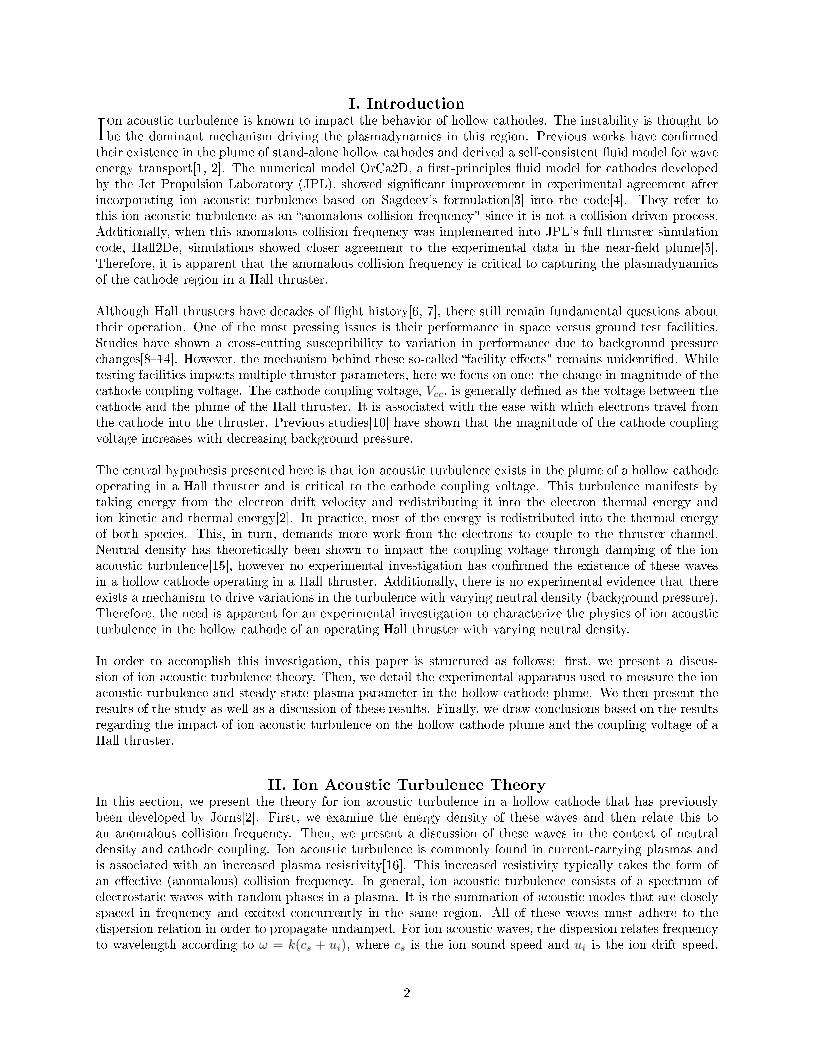
I. Introduction
Ion acoustic turbulence is known to impact the behavior of hollow cathodes. The instability is thought tobe the dominant mechanism driving the plasmadynamics in this region. Previous works have con�rmed
their existence in the plume of stand-alone hollow cathodes and derived a self-consistent �uid model for waveenergy transport[1, 2]. The numerical model OrCa2D, a �rst-principles �uid model for cathodes developedby the Jet Propulsion Laboratory (JPL), showed signi�cant improvement in experimental agreement afterincorporating ion acoustic turbulence based on Sagdeev's formulation[3] into the code[4]. They refer tothis ion acoustic turbulence as an �anomalous collision frequency" since it is not a collision driven process.Additionally, when this anomalous collision frequency was implemented into JPL's full thruster simulationcode, Hall2De, simulations showed closer agreement to the experimental data in the near-�eld plume[5].Therefore, it is apparent that the anomalous collision frequency is critical to capturing the plasmadynamicsof the cathode region in a Hall thruster.
Although Hall thrusters have decades of �ight history[6, 7], there still remain fundamental questions abouttheir operation. One of the most pressing issues is their performance in space versus ground test facilities.Studies have shown a cross-cutting susceptibility to variation in performance due to background pressurechanges[8�14]. However, the mechanism behind these so-called �facility e�ects" remains unidenti�ed. Whiletesting facilities impacts multiple thruster parameters, here we focus on one: the change in magnitude of thecathode coupling voltage. The cathode coupling voltage, Vcc, is generally de�ned as the voltage between thecathode and the plume of the Hall thruster. It is associated with the ease with which electrons travel fromthe cathode into the thruster. Previous studies[10] have shown that the magnitude of the cathode couplingvoltage increases with decreasing background pressure.
The central hypothesis presented here is that ion acoustic turbulence exists in the plume of a hollow cathodeoperating in a Hall thruster and is critical to the cathode coupling voltage. This turbulence manifests bytaking energy from the electron drift velocity and redistributing it into the electron thermal energy andion kinetic and thermal energy[2]. In practice, most of the energy is redistributed into the thermal energyof both species. This, in turn, demands more work from the electrons to couple to the thruster channel.Neutral density has theoretically been shown to impact the coupling voltage through damping of the ionacoustic turbulence[15], however no experimental investigation has con�rmed the existence of these wavesin a hollow cathode operating in a Hall thruster. Additionally, there is no experimental evidence that thereexists a mechanism to drive variations in the turbulence with varying neutral density (background pressure).Therefore, the need is apparent for an experimental investigation to characterize the physics of ion acousticturbulence in the hollow cathode of an operating Hall thruster with varying neutral density.
In order to accomplish this investigation, this paper is structured as follows: �rst, we present a discus-sion of ion acoustic turbulence theory. Then, we detail the experimental apparatus used to measure the ionacoustic turbulence and steady-state plasma parameter in the hollow cathode plume. We then present theresults of the study as well as a discussion of these results. Finally, we draw conclusions based on the resultsregarding the impact of ion acoustic turbulence on the hollow cathode plume and the coupling voltage of aHall thruster.
II. Ion Acoustic Turbulence TheoryIn this section, we present the theory for ion acoustic turbulence in a hollow cathode that has previouslybeen developed by Jorns[2]. First, we examine the energy density of these waves and then relate this toan anomalous collision frequency. Then, we present a discussion of these waves in the context of neutraldensity and cathode coupling. Ion acoustic turbulence is commonly found in current-carrying plasmas andis associated with an increased plasma resistivity[16]. This increased resistivity typically takes the form ofan e�ective (anomalous) collision frequency. In general, ion acoustic turbulence consists of a spectrum ofelectrostatic waves with random phases in a plasma. It is the summation of acoustic modes that are closelyspaced in frequency and excited concurrently in the same region. All of these waves must adhere to thedispersion relation in order to propagate undamped. For ion acoustic waves, the dispersion relates frequencyto wavelength according to ω = k(cs + ui), where cs is the ion sound speed and ui is the ion drift speed.
2

We can calculate the total wave energy density of the acoustic waves by summing the energy density of eachmode over frequency space as[2, 17],
W =neTe
ωpi∑ω0
[qφ(ω)]2 (1)
where W is the wave energy density, ωpi is the ion plasma frequency, and ω0 is the cuto� frequency. Thelower bound in Equation 1 is the frequency below which we do not expect to see ion acoustic turbulenceand thus accounting for lower frequencies would include contributions not associated with ion acoustic tur-bulence. This cuto� is associated with ion-neutral damping[2]. This method was previously employed byDodson[18] and Jorns[1]. Here, the cuto� frequency is taken as 200 kHz. The high frequency cuto� repre-sents a departure from linear growth and is thought to be the result of non-linear saturation such as electrontrapping[19], ion resonance broadening[20, 21] or non-linear ion Landau damping[22].
The anomalous collision frequency due to ion acoustic turbulence can be approximated via weak-turbulenttheory described by Sagdeev and Galeev[3]. Under the assumption that the damping at high frequency isthe result of non-linear ion Landau damping[1], this formulation is
νan = αωpeW
nTe(2)
where ωpe is the electron plasma frequency, and α is an empirically driven constant found to be O(10−2).Assuming that the waves are one-directional with the electron drift[23], we can substitute Equation 1 intoEquation 2 to get,
νan =αωpeT 2e
ωpi∑ω
[qφ(ω)]2 (3)
Previous work[1] has shown that neutral-ion collisions act to damp the growth of these modes. At con-stant current, there should be more neutral-ion collisions with increasing neutral density without a�ectingthe growth from inverse Landau damping of electrons. Saturation of these waves occurs when the dampingterms balance the growth terms. Increasing the neutral density should increase the neutral damping andtherefore lower the wave energy density amplitude[23]. In turn, as the neutral density increases, the ionacoustic turbulence should decrease[23]. Since the ion acoustic turbulence takes energy from the electrondrift, an increase in the energy density would slow the electrons more. This should make it harder for elec-trons to travel from the cathode to the thruster plume. Therefore, we expect that as the total wave energydensity increases, the voltage required to extract electron from the cathode, Vcc, should increase. Bringingthis all together, this would indicate that we should expect the cathode coupling voltage to increase as theneutral density decreases due to increasing turbulent energy.
In order to experimentally investigate this, we thus look for evidence of ion acoustic turbulence in thehollow cathode of an operating in a Hall thruster. Additionally, we aim to look at the variation in waveenergy density and cathode coupling change with neutral density.
III. Experimental ApparatusThis section outlines the experimental apparatus used to obtain cathode coupling voltage and wave energydensity measurements.
A. Thruster
We used the H9 Hall thruster for this experiment. The thruster is a single channel magnetically shielded Hallthruster jointly developed by NASA's Jet Propulsion Laboratory, the University of Michigan and the AirForce Research Laboratory[24, 25]. The thruster has a nominal power level of 9 kW and a similar design toother state-of-the art Hall thrusters. During this campaign, the thruster was run at a power level of 4.5 kW,
3
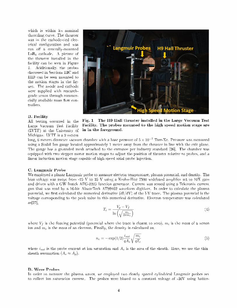
Fig. 1 The H9 Hall thruster installed in the Large Vacuum Test
Facility. The probes mounted to the high speed motion stage are
in in the foreground.
which is within its nominalthrottling curve. The thrusterwas in the cathode-tied elec-trical con�guration and wasrun o� a centrally-mountedLaB6 cathode. A picture ofthe thruster installed in thefacility can be seen in Figure1. Additionally, the probesdiscussed in Sections IIIC andIIID can be seen mounted tothe motion stages in the �g-ure. The anode and cathodewere supplied with research-grade xenon through commer-cially available mass �ow con-trollers.
B. Facility
All testing occurred in theLarge Vacuum Test Facility(LVTF) at the University ofMichigan. LVTF is a 9 meterslong, 6 meters diameter vacuum chamber with a base pressure of 5× 10⁻⁷ Torr-Xe. Pressure was measuredusing a Stabil Ion gauge located approximately 1 meter away from the thruster in line with the exit plane.The gauge has a grounded mesh attached to the entrance per industry standard [26]. The chamber wasequipped with two stepper motor motion stages to adjust the position of thruster relative to probes, and alinear induction motion stage capable of high speed axial probe injection.
C. Langmuir Probe
We employed a planar Langmuir probe to measure electron temperature, plasma potential, and density. Thebias voltage was swept from -25 V to 25 V using a Krohn-Hite 7500 wideband ampli�er set to 10X gainand driven with a GW Instek AFG-2225 function generator. Current was sensed using a Tektronix currentgun that was read by a 16-bit AlazarTech ATS9462 waveform digitizer. In order to calculate the plasmapotential, we �rst calculated the numerical derivative (dI/dV) of the I-V trace. The plasma potential is thevoltage corresponding to the peak value in this numerical derivative. Electron temperature was calculatedas[27],
Te =Vp − Vf
ln(√
mi
2πme
) (4)
where Vf is the �oating potential (potential where the trace is closest to zero), mi is the mass of a xenonion and me is the mass of an electron. Finally, the density is calculated as,
ne = − exp(1/2)isatqAs
√mi
qTe(5)
where isat is the probe current at ion saturation and As is the area of the sheath. Here, we use the thin-sheath assumption (As ≈ Ap).
D. Wave Probes
In order to measure the plasma waves, we employed two closely spaced cylindrical Langmuir probes setto collect ion saturation current. The probes were biased to a constant voltage of -36V using batter-
4
ies. The time-resolved current was inferred by measuring the voltage drop across a 100 Ohm low induc-tance metal foil resistor with another 16-bit ATS9462 analog waveform digitizer with a 65 MHz band-width. In order to obtain wave properties, a cross-correlation between the two probes was performed todetermine the dispersion of the plasma[2, 23]. Speci�cally, the Beall method analysis was used to pro-duce wave intensity plots of wavenumber vs frequency. The vector between the two probes de�ned thedirectional component of the wave being measured[28]. The power density traces were places into 10kHz bins to reduce noise in the high frequency spectrum. The probes were spaced 5.5 mm apart foraxial measurements. We binned the cross-correlation values into wavenumber bins of 8 rads/m. Addi-tionally, for low amplitude (i.e. φ << Te) electrostatic waves, we related the potential �uctuations as[2],
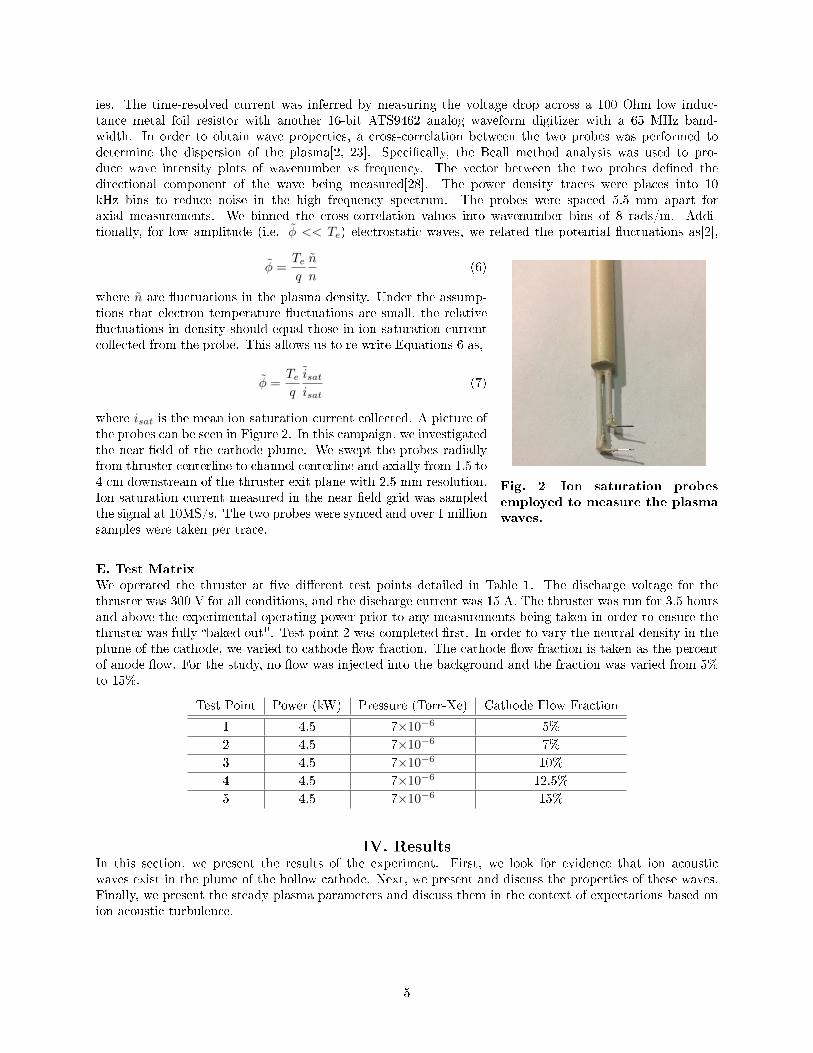
Fig. 2 Ion saturation probes
employed to measure the plasma
waves.
φ =Teq
n
n(6)
where n are �uctuations in the plasma density. Under the assump-tions that electron temperature �uctuations are small, the relative�uctuations in density should equal those in ion saturation currentcollected from the probe. This allows us to re-write Equations 6 as,
φ =Teq
isatisat
(7)
where isat is the mean ion saturation current collected. A picture ofthe probes can be seen in Figure 2. In this campaign, we investigatedthe near-�eld of the cathode plume. We swept the probes radiallyfrom thruster centerline to channel centerline and axially from 1.5 to4 cm downstream of the thruster exit plane with 2.5 mm resolution.Ion saturation current measured in the near �eld grid was sampledthe signal at 10MS/s. The two probes were synced and over 1 millionsamples were taken per trace.
E. Test Matrix
We operated the thruster at �ve di�erent test points detailed in Table 1. The discharge voltage for thethruster was 300 V for all conditions, and the discharge current was 15 A. The thruster was run for 3.5 hoursand above the experimental operating power prior to any measurements being taken in order to ensure thethruster was fully �baked-out". Test point 2 was completed �rst. In order to vary the neutral density in theplume of the cathode, we varied to cathode �ow fraction. The cathode �ow fraction is taken as the percentof anode �ow. For the study, no �ow was injected into the background and the fraction was varied from 5%to 15%.
Test Point Power (kW) Pressure (Torr-Xe) Cathode Flow Fraction
1 4.5 7×10⁻⁶ 5%
2 4.5 7×10⁻⁶ 7%
3 4.5 7×10⁻⁶ 10%
4 4.5 7×10⁻⁶ 12.5%
5 4.5 7×10⁻⁶ 15%
IV. ResultsIn this section, we present the results of the experiment. First, we look for evidence that ion acousticwaves exist in the plume of the hollow cathode. Next, we present and discuss the properties of these waves.Finally, we present the steady plasma parameters and discuss them in the context of expectations based onion acoustic turbulence.
5
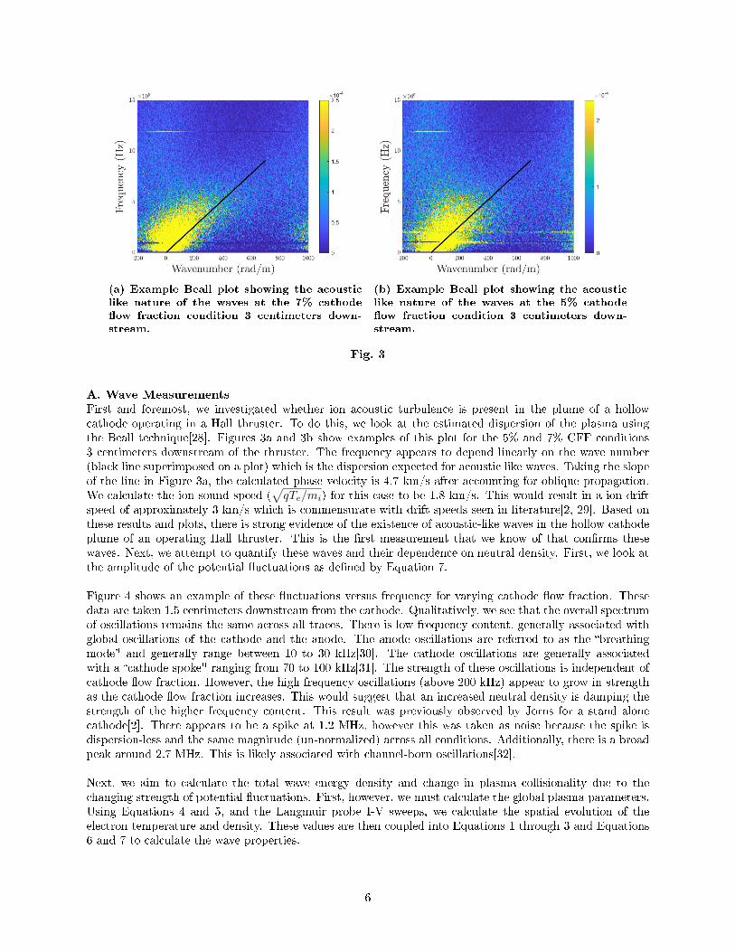
(a) Example Beall plot showing the acousticlike nature of the waves at the 7% cathode�ow fraction condition 3 centimeters down-stream.
(b) Example Beall plot showing the acousticlike nature of the waves at the 5% cathode�ow fraction condition 3 centimeters down-stream.
Fig. 3
A. Wave Measurements
First and foremost, we investigated whether ion acoustic turbulence is present in the plume of a hollowcathode operating in a Hall thruster. To do this, we look at the estimated dispersion of the plasma usingthe Beall technique[28]. Figures 3a and 3b show examples of this plot for the 5% and 7% CFF conditions3 centimeters downstream of the thruster. The frequency appears to depend linearly on the wave number(black line superimposed on a plot) which is the dispersion expected for acoustic like waves. Taking the slopeof the line in Figure 3a, the calculated phase velocity is 4.7 km/s after accounting for oblique propagation.We calculate the ion sound speed (
√qTe/mi) for this case to be 1.8 km/s. This would result in a ion drift
speed of approximately 3 km/s which is commensurate with drift speeds seen in literature[2, 29]. Based onthese results and plots, there is strong evidence of the existence of acoustic-like waves in the hollow cathodeplume of an operating Hall thruster. This is the �rst measurement that we know of that con�rms thesewaves. Next, we attempt to quantify these waves and their dependence on neutral density. First, we look atthe amplitude of the potential �uctuations as de�ned by Equation 7.
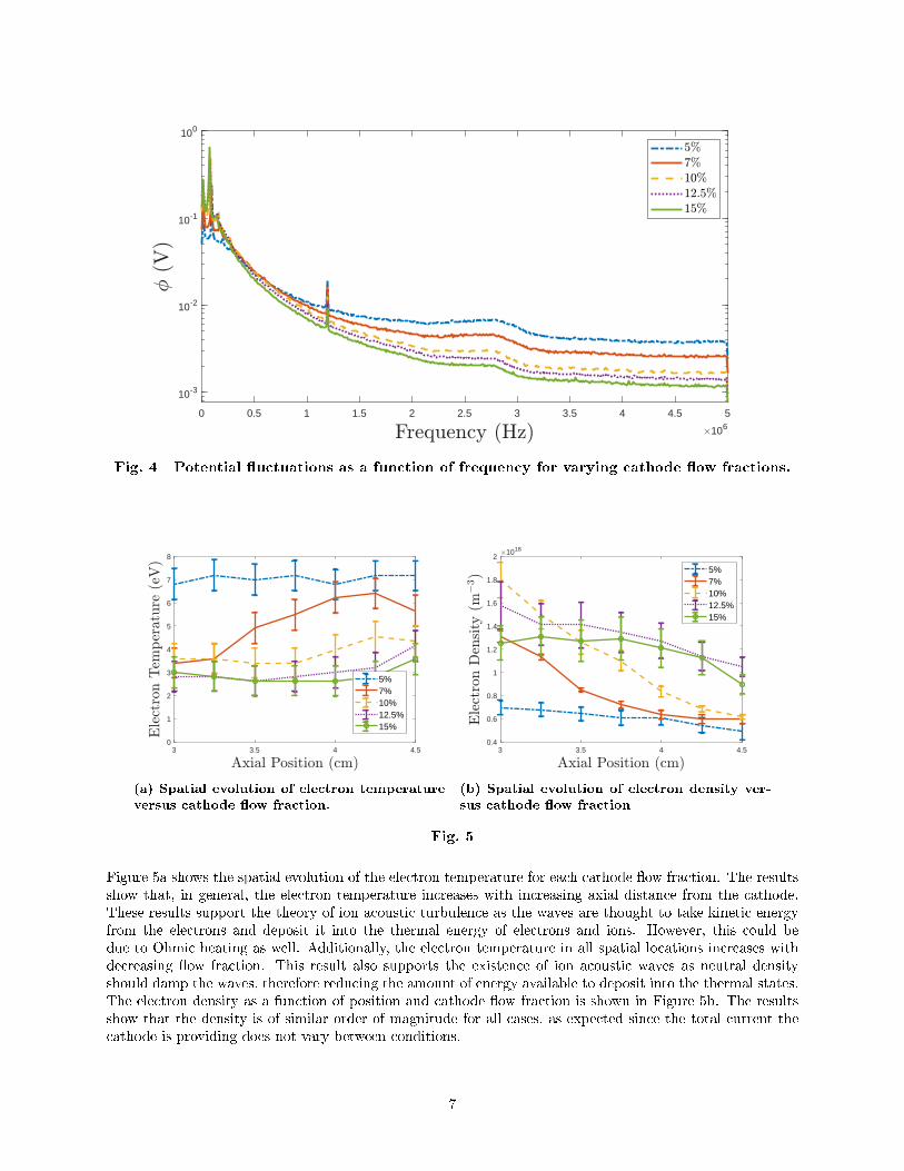
Figure 4 shows an example of these �uctuations versus frequency for varying cathode �ow fraction. Thesedata are taken 1.5 centimeters downstream from the cathode. Qualitatively, we see that the overall spectrumof oscillations remains the same across all traces. There is low frequency content, generally associated withglobal oscillations of the cathode and the anode. The anode oscillations are referred to as the �breathingmode" and generally range between 10 to 30 kHz[30]. The cathode oscillations are generally associatedwith a �cathode spoke" ranging from 70 to 100 kHz[31]. The strength of these oscillations is independent ofcathode �ow fraction. However, the high frequency oscillations (above 200 kHz) appear to grow in strengthas the cathode �ow fraction increases. This would suggest that an increased neutral density is damping thestrength of the higher frequency content. This result was previously observed by Jorns for a stand alonecathode[2]. There appears to be a spike at 1.2 MHz, however this was taken as noise because the spike isdispersion-less and the same magnitude (un-normalized) across all conditions. Additionally, there is a broadpeak around 2.7 MHz. This is likely associated with channel-born oscillations[32].
Next, we aim to calculate the total wave energy density and change in plasma collisionality due to thechanging strength of potential �uctuations. First, however, we must calculate the global plasma parameters.Using Equations 4 and 5, and the Langmuir probe I-V sweeps, we calculate the spatial evolution of theelectron temperature and density. These values are then coupled into Equations 1 through 3 and Equations6 and 7 to calculate the wave properties.
6
0 0.5 1 1.5 2 2.5 3 3.5 4 4.5 5
106
10-3
10-2
10-1
100
Fig. 4 Potential �uctuations as a function of frequency for varying cathode �ow fractions.
3 3.5 4 4.50
1
2
3
4
5
6
7
8
5%7%10%12.5%15%
(a) Spatial evolution of electron temperatureversus cathode �ow fraction.
3 3.5 4 4.50.4
0.6
0.8
1
1.2
1.4
1.6
1.8
21018
5%7%10%12.5%15%
(b) Spatial evolution of electron density ver-sus cathode �ow fraction
Fig. 5
Figure 5a shows the spatial evolution of the electron temperature for each cathode �ow fraction. The resultsshow that, in general, the electron temperature increases with increasing axial distance from the cathode.These results support the theory of ion acoustic turbulence as the waves are thought to take kinetic energyfrom the electrons and deposit it into the thermal energy of electrons and ions. However, this could bedue to Ohmic heating as well. Additionally, the electron temperature in all spatial locations increases withdecreasing �ow fraction. This result also supports the existence of ion acoustic waves as neutral densityshould damp the waves, therefore reducing the amount of energy available to deposit into the thermal states.The electron density as a function of position and cathode �ow fraction is shown in Figure 5b. The resultsshow that the density is of similar order of magnitude for all cases, as expected since the total current thecathode is providing does not vary between conditions.
7

We now look at the results from calculating the wave energy density and anomalous collision frequencywith respect to position for varying cathode �ow fractions. These results are seen in Figures 6a and 6b.There are two points of interest in the �uctuation strength plot: (1) the peak value increases with decreasing�ow fraction and (2) the waves peak closer to the cathode with decreasing �ow fraction. In Figure 6b, wesee that the collision frequency appears to decrease as a function of position. Additionally, the values forcollision frequency seen here are of the same order of magnitude previously reported[4].
1.5 2 2.5 3 3.5 40.03
0.04
0.05
0.06
0.07
0.08
0.09
0.1
0.11
0.12
0.13
(a) Relative strength of oscillation as a functionof position for each cathode �ow fraction case.
3 3.1 3.2 3.3 3.4 3.5 3.6 3.7 3.8 3.9 4107
108
(b) Anomalous collision frequency due to ionacoustic turbulence for each cathode �ow frac-tion case.
Fig. 6
V. DiscussionIn this section, we discuss the results presented above in the context of dominance in the plume and theimpact on the thruster operation.
3 3.1 3.2 3.3 3.4 3.5 3.6 3.7 3.8 3.9 4100
101
102
(a) Ratio of collision frequency due to ion acous-tic turbulence and classical Coulomb collisions.
5 6 7 8 9 10 11 12 13 14 154
6
8
10
12
14
16
18
20
(b) Average ratio of collision frequency due to ionacoustic turbulence and classical Coulomb colli-sions as a function of cathode �ow fraction.
Fig. 7
Figure 6b shows the total e�ective collision frequency due to ion acoustic turbulence. However, it is impos-
8
sible to frame these results without comparing them to the classic collision frequencies. If, these e�ectivefrequencies are orders of magnitude smaller than classically expected, then we would not expect ion acous-tic turbulence to play an important role in this region. However, if they are an appreciable fraction orlarger than classically expected, that would indicate that ion acoustic turbulence is important to considerin the plasmadynamics of the region. We calculate the classical collision frequency as the Coulomb collisionfrequency. The formulation for this is[33],
νei = 2.9× 10⁻¹²ne
T3/2e
[23− 1
2log
(10−6neT 3e
)](8)
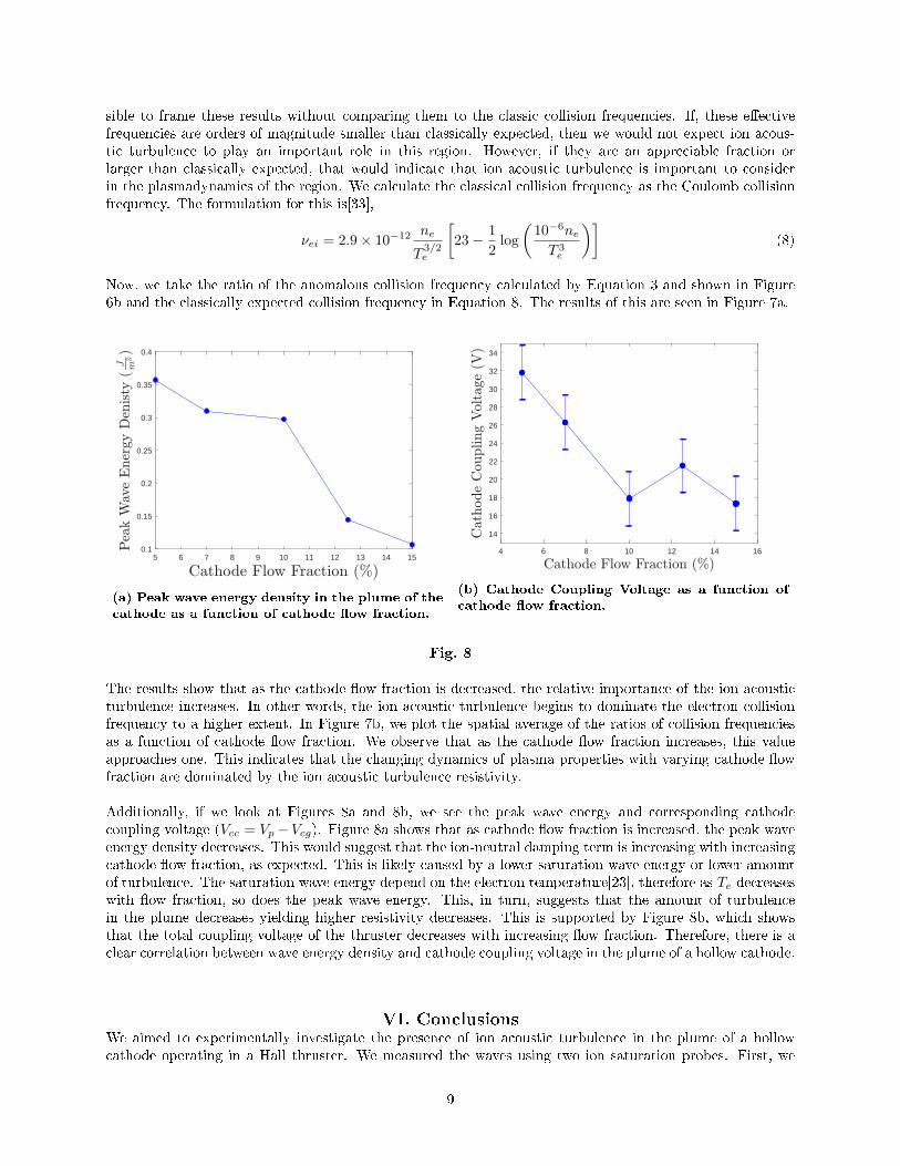
Now, we take the ratio of the anomalous collision frequency calculated by Equation 3 and shown in Figure6b and the classically expected collision frequency in Equation 8. The results of this are seen in Figure 7a.
5 6 7 8 9 10 11 12 13 14 150.1
0.15
0.2
0.25
0.3
0.35
0.4
(a) Peak wave energy density in the plume of thecathode as a function of cathode �ow fraction.
4 6 8 10 12 14 16
14
16
18
20
22
24
26
28
30
32
34
(b) Cathode Coupling Voltage as a function ofcathode �ow fraction.
Fig. 8
The results show that as the cathode �ow fraction is decreased, the relative importance of the ion acousticturbulence increases. In other words, the ion acoustic turbulence begins to dominate the electron collisionfrequency to a higher extent. In Figure 7b, we plot the spatial average of the ratios of collision frequenciesas a function of cathode �ow fraction. We observe that as the cathode �ow fraction increases, this valueapproaches one. This indicates that the changing dynamics of plasma properties with varying cathode �owfraction are dominated by the ion acoustic turbulence resistivity.
Additionally, if we look at Figures 8a and 8b, we see the peak wave energy and corresponding cathodecoupling voltage (Vcc = Vp−Vcg). Figure 8a shows that as cathode �ow fraction is increased, the peak waveenergy density decreases. This would suggest that the ion-neutral damping term is increasing with increasingcathode �ow fraction, as expected. This is likely caused by a lower saturation wave energy or lower amountof turbulence. The saturation wave energy depend on the electron temperature[23], therefore as Te decreaseswith �ow fraction, so does the peak wave energy. This, in turn, suggests that the amount of turbulencein the plume decreases yielding higher resistivity decreases. This is supported by Figure 8b, which showsthat the total coupling voltage of the thruster decreases with increasing �ow fraction. Therefore, there is aclear correlation between wave energy density and cathode coupling voltage in the plume of a hollow cathode.
VI. ConclusionsWe aimed to experimentally investigate the presence of ion acoustic turbulence in the plume of a hollowcathode operating in a Hall thruster. We measured the waves using two ion saturation probes. First, we
9

proved the existence of ion acoustic waves in the hollow cathode plume operating in a Hall thruster. Wethen showed that the relative strength of the collision frequency as compared to classical collision frequenciesgrows as neutral density drops. Additionally, we showed that both the peak wave energy density and thetotal thruster coupling voltage decrease with increasing cathode �ow fraction. Therefore, we concluded thatneutral density drops in the plume of a hollow cathode may increase the strength of ion acoustic turbulencetherefore increasing the coupling voltage. Particularly for externally mounted hollow cathodes, this wouldsuggest that the changes observed in coupling versus background pressure are due to the onset of ion acousticturbulence.
AcknowledgmentsThe authors would like to thank the entirety of the Plasmadynamics and Electric Propulsion Laboratory
for their assistance and advice throughout the duration of the experiment. The authors would like to acknowl-edge funding provided by the NASA Space Technology Research Fellowship grant numbers NNX15AQ43Hand NNX14AL65H, NSF GRFP grant number DGE 1256260 and AFOSR grant number FA9550-17-1-0035.
References[1] Jorns, B., Lopez Ortega, A., and Mikellides, I. G., �First-principles modelling of the IAT-driven anomalous
resistivity in hollow cathode discharges I: Theory,� 52nd AIAA/SAE/ASEE Joint Propulsion Conference, 2016,p. 4626.
[2] Jorns, B. A., Mikellides, I. G., and Goebel, D. M., �Ion acoustic turbulence in a 100-A LaB 6 hollow cathode,�Physical Review E, Vol. 90, No. 6, 2014, p. 063106.
[3] Sagdeev, R. Z., and Galeev, A. A., �Nonlinear plasma theory,� Nonlinear Plasma Theory, New York: Benjamin,1969, 1969.
[4] Lopez Ortega, A., Mikellides, I. G., and Jorns, B., �First-principles modeling of the IAT-driven anomalousresistivity in hollow cathode discharges II: Numerical simulations and comparison with measurements,� 52ndAIAA/SAE/ASEE Joint Propulsion Conference, 2016, p. 4627.
[5] Lopez Ortega, A., and Mikellides, I. G., �The importance of the cathode plume and its interactions with the ionbeam in numerical simulations of Hall thrusters,� Physics of Plasmas, Vol. 23, No. 4, 2016, p. 043515.
[6] Morozov, A., �The conceptual development of stationary plasma thrusters,� Plasma Physics Reports, Vol. 29,No. 3, 2003, pp. 235�250.
[7] Morozov, A., and Savelyev, V., �Fundamentals of stationary plasma thruster theory,� Reviews of plasma physics,Springer, 2000, pp. 203�391.
[8] Randolph, T., Kim, V., Kaufman, H., Kozubsky, K., Zhurin, V., and Day, M., �Facility e�ects on stationaryplasma thruster testing,� 23rd International Electric Propulsion Conference, 1993, pp. 1993�093.
[9] Hofer, R. R., and Anderson, J. R., �Finite Pressure E�ects in Magnetically Shielded Hall Thrusters,� 50thAIAA/ASME/SAE/ASEE Joint Propulsion Conference, 2014, p. 3709.
[10] Huang, W., Kamhawi, H., and Haag, T., �Facility e�ect characterization test of NASA's HERMes Hall thruster,�52nd AIAA/SAE/ASEE Joint Propulsion Conference, 2016, p. 4828.
[11] Nakles, M., and Hargus, W., �Background pressure e�ects on internal and near-�eld ion velocity distribution ofthe BHT-600 Hall thruster,� 44th AIAA/ASME/SAE/ASEE Joint Propulsion Conference & Exhibit, 2008, p.5101.
[12] Hofer, R. R., Peterson, P. Y., and Gallimore, A. D., �Characterizing vacuum facility backpressure e�ects onthe performance of a Hall thruster,� IEPC-01-045, 27th International Electric Propulsion Conference, Pasadena,CA, 2001.
[13] Huang, W., Kamhawi, H., and Haag, T., �E�ect of background pressure on the performance and plume of thehivhac hall thruster,� 2013.
10

[14] Spektor, R., and Tighe, W. G., �Laser Induced Fluorescence Measurements in a Hall Thruster as a Function ofBackground Pressure,� 52nd AIAA/SAE/ASEE Joint Propulsion Conference, 2016, p. 4624.
[15] Cusson, S. E., Jorns, B., and Gallimore, A., �Simple Model for Cathode Coupling Voltage Versus BackgroundPressure in a Hall Thruster,� 53rd AIAA/SAE/ASEE Joint Propulsion Conference, 2017, p. 4889.
[16] Horton, C. W., and Horton, W., Turbulent transport in magnetized plasmas, World Scienti�c, 2012.
[17] Stix, T., �Plasma waves,� A. I. P., New York, 1992.
[18] Dodson, C., Perez-Grande, D., Jorns, B., Goebel, D. M., and Wirz, R. E., �Laser-induced �uorescence mea-surements of energetic Ions in a 100-A LaB6 hollow cathode plume,� 52nd AIAA/SAE/ASEE Joint PropulsionConference, 2016, p. 4838.
[19] Nishikawa, K., and Wu, C.-S., �E�ect of electron trapping on the ion-wave instability,� Physical Review Letters,Vol. 23, No. 18, 1969, p. 1020.
[20] Sleeper, A. M., Weinstock, J., and Bezzerides, B., �Nonlinear theory and angular spectrum of the ion-acousticinstability,� The Physics of Fluids, Vol. 16, No. 9, 1973, pp. 1508�1518.
[21] Basu, A., Sharma, A. S., and Das, A., �Spectrum of turbulent ion acoustic waves in a magnetic �eld,� Plasmaphysics and controlled fusion, Vol. 27, No. 4, 1985, p. 433.
[22] Kadomtsev, B. B., �Plasma turbulence,� New York: Academic Press, 1965, 1965.
[23] Jorns, B. A., Dodson, C., Goebel, D. M., and Wirz, R., �Propagation of ion acoustic wave energy in the plumeof a high-current LaB 6 hollow cathode,� Physical Review E, Vol. 96, No. 2, 2017, p. 023208.
[24] Hofer, R. R., Cusson, S. E., Lobbia, R. B., and Gallimore, A. D., �The H9 Magnetically Shielded Hall Thruster,�35th International Electric Propulsion Conference, Atlanta,GA, 2017.
[25] Cusson, S. E., Hofer, R. R., Lobbia, R. B., Jorns, B. A., and Gallimore, A. D., �Performance of the H9 Magnet-ically Shielded Hall Thrusters,� 2017.
[26] Dankanich, J. W., Walker, M., Swiatek, M. W., and Yim, J. T., �Recommended Practice for Pressure Measure-ment and Calculation of E�ective Pumping Speed in Electric Propulsion Testing,� Journal of Propulsion andPower, 2016.
[27] Lobbia, R. B., and Beal, B. E., �Recommended Practice for Use of Langmuir Probes in Electric PropulsionTesting,� Journal of Propulsion and Power, 2017, pp. 1�16.
[28] Beall, J., Kim, Y., and Powers, E., �Estimation of wavenumber and frequency spectra using �xed probe pairs,�Journal of Applied Physics, Vol. 53, No. 6, 1982, pp. 3933�3940.
[29] Williams, G. J., Smith, T. B., Domonkos, M. T., Gallimore, A. D., and Drake, R. P., �Laser-induced �uorescencecharacterization of ions emitted from hollow cathodes,� IEEE Transactions on Plasma Science, Vol. 28, No. 5,2000, pp. 1664�1675.
[30] Choueiri, E., �Plasma oscillations in Hall thrusters,� Physics of Plasmas, Vol. 8, No. 4, 2001, pp. 1411�1426.
[31] Jorns, B. A., and Hofer, R. R., �Plasma oscillations in a 6-kW magnetically shielded Hall thruster,� Physics ofPlasmas, Vol. 21, No. 5, 2014, p. 053512.
[32] Brown, Z. A., and Jorns, B. A., �Spatial Evolution of Plasma Waves in the Acceleration Region and Near Fieldof a Magnetically Shielded Hall Thruster,� 54th AIAA/SAE/ASEE Joint Propulsion Conference, 2018.
[33] Goebel, D. M., and Katz, I., Fundamentals of Electric Propulsion: Ion and Hall Thrusters, Vol. 1, John Wiley& Sons, 2008.
11


