24
IONIZER USER MANUAL Model 2400 AirStat ® Digital Ceiling Emitter Ionizer
IONIZERU S E RMANUALModel 2400AirStat® Digital Ceiling Emitter Ionizer

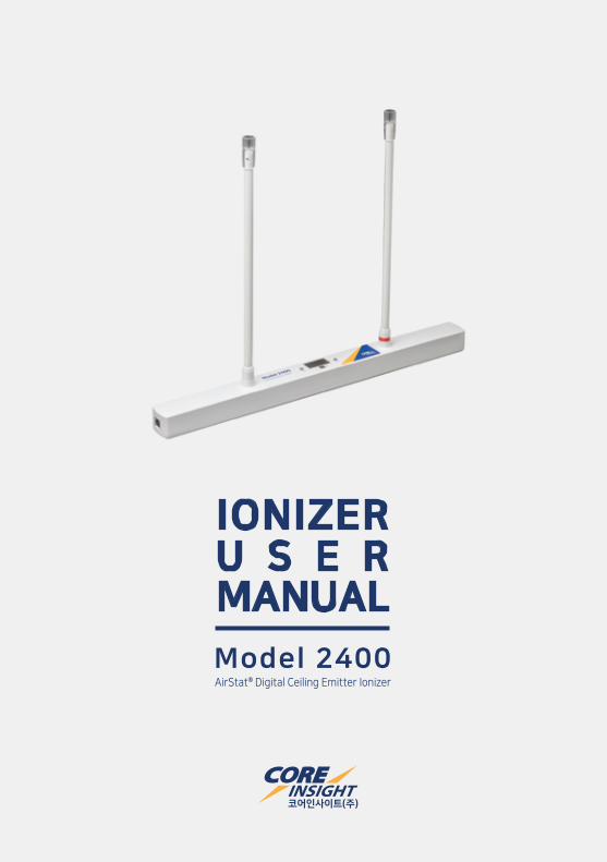
AirStat® Digital Ceiling Emitter Ionizer
IONIZERU S E RMANUALModel 2400
IONIZER USER MANUAL3
Contents
1. Core Insight Introduction
2. Ionization Technology A. Steady State DC Ionization
B. AC Ionization
C. Bipolar Pulsed AC Ionization
D. High Frequency AC Ionization
E. Pulsed DC Ionization
3. Application Guide A. Basic ESD Control
B. Ionization for CDM/CBE Controls
4. Cautions and Personal Safety A. Cautions
B. Personal Safety
5. General Specification
6. Drawings
7. Setup and Operation A. Introduction
B. Contents in the box
C. Descriptions for Model 2400
D. Installation
E. Turning on the ionizer
F. Parameter Settings
8. Maintenance
9. Warranty and Services
4
5
7
9
11
12
12
21
22
Core Insight Introduction
Core Insight is an ionization system manufacturer and supplier to ESD and
contamination control areas. Core Insight also provides ESD Test and
Measurement equipment, Professional Audit Kits, EMI Noise Filters and
EOS/ESD Technical Services include ESD Training, Process Assessment, ESD
Control Program Development, Product Qualification Testing per ANSI/ESD
Standards, Device Testing and System Level ESD Testing per IEC 61000-4-2.
Core Insight is a major ESD supplier in the fields of semiconductors, flat
panel displays, automotive, and electronic manufacturing. Core Insight was
founded in 2003 and is a representative for ProStat, On-Filter, Monroe
Electronics, Electro-Tech Systems, and Dangelmayer Associates etc.
1
4Copyright by CORE INSIGHT, INC.This user manual contents may change without pre-notification.
The CoreStat® Self-Balanced Ionization System uses steady-state DC
ionization technology with an isolated high voltage section in its power
supply. It maintains intrinsically balanced offset voltage performance
within its specification ranges. All Model 300 series and Model 3000 series
ionizers use CoreStat® steady-state DC technology which does not need
adjustment of ion output to maintain balance performance. Only periodic
cleaning emitter points is needed for maintaining decay performance.
Core Insight also offers traditional AC ionization technology for industrial
applications such as roll to roll or winding & unwinding of films for
static-related contamination issues.
Core Insight offers bipolar Pulsed AC ionizers which operate at a lower
frequency than conventional AC ionizers. The ionizer output parameters
are adjustable for applications such as flat panel display (FPD) and other
manufacturing environments.
High Frequency AC is alternative solution for replacement of conventional
AC for ESD control applications requiring very small package sizes. This
technology uses a lower high voltage level than conventional AC ionizers,
but much faster switching time from 16k Hz to 70k Hz. This type of ionizer
can achieve low offset voltage in ESD control application areas.
IONIZER USER MANUAL5
2 Ionization Technology
Pulsed DC ionization technology is the driver of Core Insight’s ionization
products for cleanroom particle contamination control. There are many
forms and configurations for this type of product which are used to reduce
particle contamination in many work areas such as semiconductor front-end,
back-end, flat panel display factories and many other industrial applications.
Core Insight offers several types of Charged Plate Monitors (CPM) or Test
Kits for ionizer performance testing for qualification and compliance
verification. Monroe Electronics’ Model 288 is the latest version of a CPM
using a highly accurate measurement technique based on voltage follower
technology. Model 300 is cost effective ionizer measurement CPM
equipment. Both CPMs can be remotely controlled to make measurements
using software for detailed analysis and test result reporting. Both CPMs
comply with the ANSI/ESD STM3.1 standard.
For compliance verification measurements, there is a hand-held fieldmeter
based test kit which has a smaller plate, external charging source and
integrated decay timer. This test kit meets the ANSI/ESD SP3.3 test
requirement.
For more detailed information about ionization and its test equipment,
please feel free to contact our sales representative
at [email protected] or your local contacts.
6
2 Ionization Technology
Copyrignt by CORE INSIGHT, INC.This user manual contents may change without pre-notification.
IONIZER USER MANUAL7
A. Basic ESD Control
Basic ESD control requirements for the electronics industry include
personal grounding, ESD safe worksurfaces, and ESD safe packaging
materials. Methods to accomplish this are well known and it is relatively
easy to establish in ESD protected area (EPA).
B. Ionization for CDM/CBE Controls
Every device has its own ESD sensitivity and can be damaged by ESD
greater than its sensitivity limit. According to many IC suppliers, over
99% of device ESD failures are Charged Device Model (CDM) or
CDM-like and not HBM. Due to increased use of automation and device
sensitivity continually going lower, vulnerability to device CDM is
increasing. Not only CDM, but also Charge Board Event (CBE) like ESD
issues are increasing due to device complexity and the large amount of
charge that can be stored on a printed circuit board.
Strategic guidance has been proposed by the ESD Association.
Lowering device charge level and increasing the resistance of device
contact materials are the key strategic elements to prevent ESD
damage. As ANSI/ESD S20.20-2014 (latest version) described, the
maximum allowable field strength is 125 V/inch for 200 V CDM
withstand threshold devices. Proper ionization is an important solution
to meet this requirement and will result in less CDM/CBE ESD failures in
production or field returns from customers.
Core Insight provides superior solutions for static related issues with
several types of ionization products and systems such as steady-state
DC, AC, pulsed AC, high frequency AC and pulsed DC ionizations.
For more detail information about ionization and ESD controls in
production, please feel free to contact our sales representative
at [email protected] or your local contacts.
3 Application Guide
8Copyright by CORE INSIGHT, INC.This user manual contents may change without pre-notification.
A. Cautions
The use of improper input voltage may result in poor performance or
damage of the unit.
There are no user serviceable parts inside this ionizer. Any
unauthorized service will void the warranty and may result in additional
repair charge.
B. Personal Safety
Before performing any maintenance on emitter points, shut down the
power to the ionizer. Allow a minute for high voltage power supply to
discharge. Do not wear wrist straps when accessing ionizer units for
maintenance.
Cautions and Personal Safety 4
IONIZER USER MANUAL9
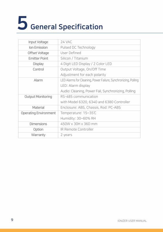
Input Voltage
Ion Emission
Offset Voltage
Emitter Point
Display
Control
Alarm
Output Monitoring
Material
Operating Environment
Dimensions
Option
Warranty
24 VAC
Pulsed DC Technology
User Defined
Silicon / Titanium
4 Digit LED Display / 2 Color LED
Output Voltage, On/Off Time
Adjustment for each polarity
LED Alarms for Cleaning, Power Failure, Synchronizing, Polling
LED: Alarm display
Audio: Cleaning, Power Fail, Synchronizing, Polling
RS-485 communication
with Model 6320, 6340 and 6380 Controller
Enclosure: ABS, Chassis, Rod: PC-ABS
Temperature: 15~35℃
Humidity: 30~60% RH
450W x 30H x 36D mm
IR Remote Controller
2 years
5 General Specification
10Copyright by CORE INSIGHT, INC.This user manual contents may change without pre-notification.
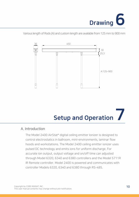
Various length of Rods (A) and custom length are available from 125 mm to 900 mm
A. Introduction
The Model 2400 AirStat® digital ceiling emitter Ionizer is designed to
control electrostatics in ballroom, mini-environments, laminar flow
hoods and workstations. The Model 2400 ceiling emitter ionizer uses
pulsed DC technology and emits ions for uniform discharge. For
accurate ion output, output voltage and on/off time can adjusted
through Model 6320, 6340 and 6380 controllers and the Model 5711R
IR Remote controller. Model 2400 is powered and communicates with
controller Models 6320, 6340 and 6380 through RS-485.
Drawing
450
30
25.3
A:125~900
36
6
Setup and Operation 7
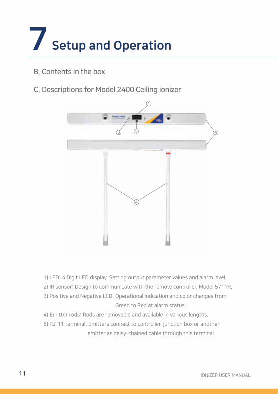
1) LED: 4 Digit LED display. Setting output parameter values and alarm level.
2) IR sensor: Design to communicate with the remote controller, Model 5711R.
3) Positive and Negative LED: Operational indication and color changes from
Green to Red at alarm status.
4) Emitter rods: Rods are removable and available in various lengths.
5) RJ-11 terminal: Emitters connect to controller, junction box or another
emitter as daisy-chained cable through this terminal.
IONIZER USER MANUAL11
B. Contents in the box
C. Descriptions for Model 2400 Ceiling ionizer
7 Setup and Operation
①
②③
④
⑤
D. Installation
Place the ceiling emitter ionizer in the desired location. For installation
of Model 2400, it is recommended to use additional brackets or other
mounting methods to securely attach the ionizers to the mounting
surface. Model 2400 is powered by Model 6320, 6340 and 6380
controllers. The maximum length of communication cable from
controller to junction box is about 10 meter and recommended cable
length between junction box and first ceiling emitter is about 5 meter.
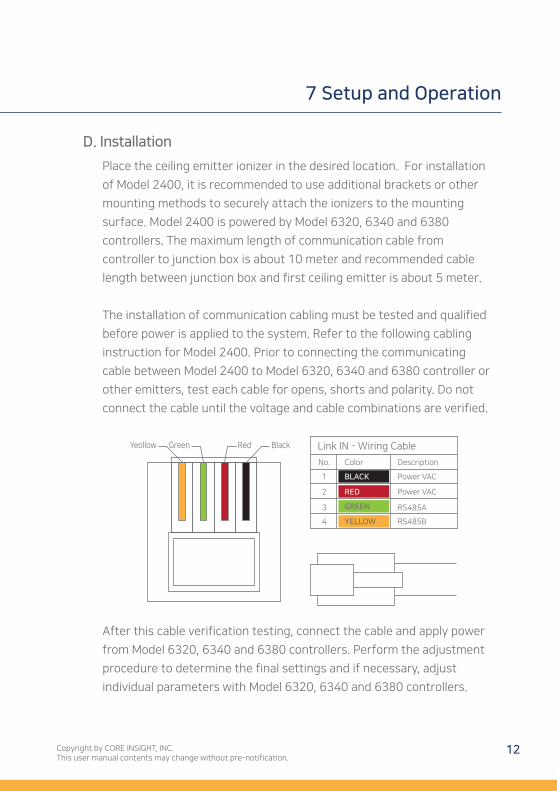
The installation of communication cabling must be tested and qualified
before power is applied to the system. Refer to the following cabling
instruction for Model 2400. Prior to connecting the communicating
cable between Model 2400 to Model 6320, 6340 and 6380 controller or
other emitters, test each cable for opens, shorts and polarity. Do not
connect the cable until the voltage and cable combinations are verified.
12Copyright by CORE INSIGHT, INC.This user manual contents may change without pre-notification.
After this cable verification testing, connect the cable and apply power
from Model 6320, 6340 and 6380 controllers. Perform the adjustment
procedure to determine the final settings and if necessary, adjust
individual parameters with Model 6320, 6340 and 6380 controllers.
7 Setup and Operation
Yeollow Green Red Black Link IN - Wiring Cable
No.
1
2
3
4
BLACK
RED
GREEN
YELLOW
Power VAC
Power VAC
RS485A
RS485B
Color Description
E. Turning on the ionizer
Once the Model 2400 is powered on, the LED will display light. Model 2400 can
communicate with Model 6320, 6340 and 6380 controllers to register the ID
number. Any number from #1 to #120 can be assigned as the ID number. Please
select the ID number desired, and after this ID registration, Model 2400 outputs
ions based on set output values.
IONIZER USER MANUAL13
7 Setup and Operation
14Copyright by CORE INSIGHT, INC.This user manual contents may change without pre-notification.
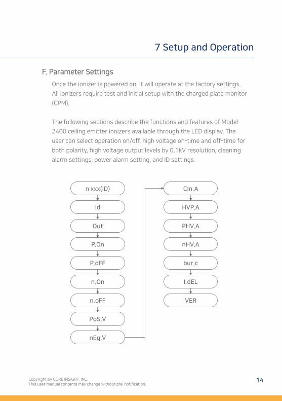
F. Parameter Settings
Once the ionizer is powered on, it will operate at the factory settings.
All ionizers require test and initial setup with the charged plate monitor
(CPM).
The following sections describe the functions and features of Model
2400 ceiling emitter ionizers available through the LED display. The
user can select operation on/off, high voltage on-time and off-time for
both polarity, high voltage output levels by 0.1kV resolution, cleaning
alarm settings, power alarm setting, and ID settings.
7 Setup and Operation
n xxx(ID) CIn.A
Id HVP.A
Out PHV.A
P.On nHV.A
P.oFF bur.c
n.On I.dEL
n.oFF
PoS.V
nEg.V
VER
IONIZER USER MANUAL15
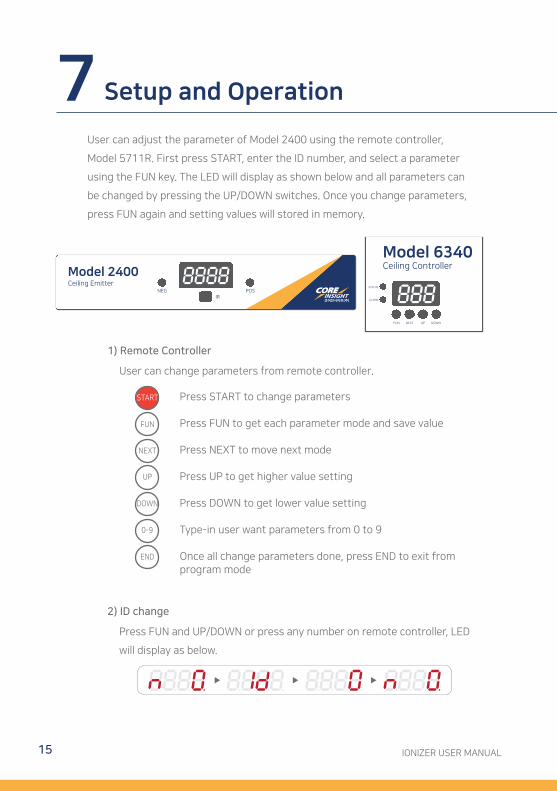
User can adjust the parameter of Model 2400 using the remote controller,
Model 5711R. First press START, enter the ID number, and select a parameter
using the FUN key. The LED will display as shown below and all parameters can
be changed by pressing the UP/DOWN switches. Once you change parameters,
press FUN again and setting values will stored in memory.
2) ID change
Press FUN and UP/DOWN or press any number on remote controller, LED
will display as below.
1) Remote Controller
User can change parameters from remote controller.
Press START to change parameters
Press FUN to get each parameter mode and save value
Press NEXT to move next mode
Press UP to get higher value setting
Press DOWN to get lower value setting
Type-in user want parameters from 0 to 9
Once all change parameters done, press END to exit from program mode
UP
DOWN
0-9
END
NEXT
FUN
START
7 Setup and Operation
16Copyright by CORE INSIGHT, INC.This user manual contents may change without pre-notification.
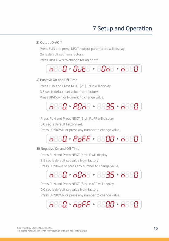
4) Positive On and Off Time
Press FUN and Press NEXT (2nd). P.On will display.
3.5 sec is default set value from factory.
Press UP/Down or Numeric to change value.
Press FUN and Press NEXT (3rd). P.oFF will display.
0.0 sec is default factory set.
Press UP/DOWN or press any number to change value.
3) Output On/Off
Press FUN and press NEXT, output parameters will display.
On is default set from factory.
Press UP/DOWN to change for on or off.
5) Negative On and Off Time
Press FUN and Press NEXT (4th). P.will display.
3.5 sec is default set value from factory
Press UP/Down or press any number to change value.
Press FUN and Press NEXT (5th). n.oFF will display.
0.0 sec is default set value from factory
Press UP/DOWN or press any number to change value.
7 Setup and Operation
IONIZER USER MANUAL17
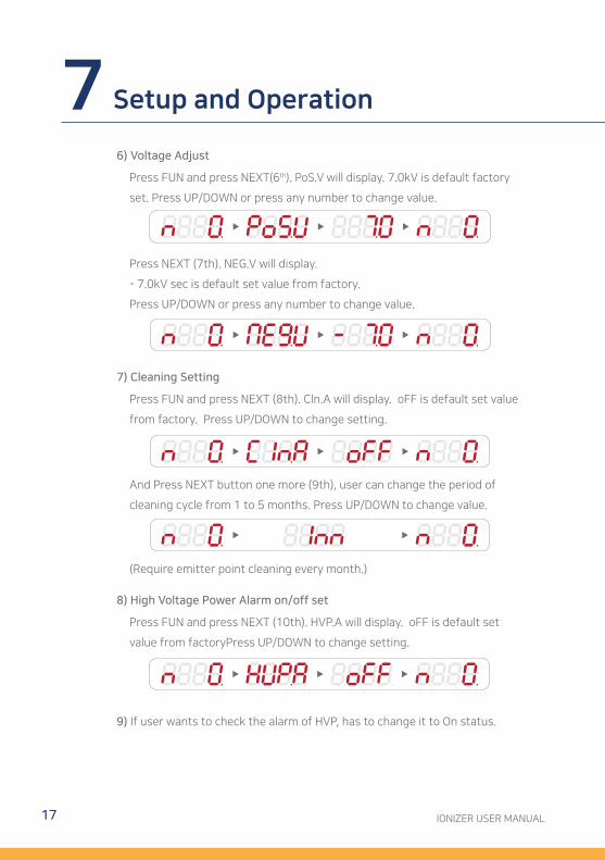
8) High Voltage Power Alarm on/off set
9) If user wants to check the alarm of HVP, has to change it to On status.
Press FUN and press NEXT (10th). HVP.A will display. oFF is default set
value from factoryPress UP/DOWN to change setting.
(Require emitter point cleaning every month.)
6) Voltage Adjust
Press FUN and press NEXT(6th). PoS.V will display. 7.0kV is default factory
set. Press UP/DOWN or press any number to change value.
Press NEXT (7th). NEG.V will display.
- 7.0kV sec is default set value from factory.
Press UP/DOWN or press any number to change value.
7) Cleaning Setting
Press FUN and press NEXT (8th). Cln.A will display. oFF is default set value
from factory. Press UP/DOWN to change setting.
And Press NEXT button one more (9th), user can change the period of
cleaning cycle from 1 to 5 months. Press UP/DOWN to change value.
7 Setup and Operation
18Copyright by CORE INSIGHT, INC.This use manual contents may change without pre-notification.
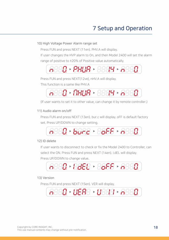
10) High Voltage Power Alarm range set
Press FUN and press NEXT (11en). PHV.A will display.
If user changes the HVP alarm to On, and then Model 2400 will set the alarm
range of positive to ±20% of Positive value automatically.
Press FUN and press NEXT(12ve), nHV.A will display.
This function is a same like PHV.A
(If user wants to set it to other value, can change it by remote controller.)
11) Audio alarm on/off
Press FUN and press NEXT (13en). bur.c will display. oFF is default factory
set. Press UP/DOWN to change setting.
12) ID delete
If user wants to disconnect to check or fix the Model 2400 to Controller, can
select the ON. Press FUN and press NEXT (14en). I.dEL will display.
Press UP/DOWN to change value.
13) Version
Press FUN and press NEXT (15en). VER will display.
7 Setup and Operation
A. Recommended Cleaning Materials:
1) Cleanroom-compatible cleaning cloths (polyester cloth is recommended)
2) Cleanroom-compatible swabs
3) Cleanroom solution of 50% IPA (electronic-grade isopropanol) / 50% de-ionized water
B. Cleaning inside of Enclosures
Moisten a cloth with the IPA solution. Wipe off any dirt that may have
accumulated inside of the unit.
C. Cleaning the Emitter Points
Turn off the unit. A swab moistened with the IPA solution may be used for
cleaning. Gently wipe the tips of the emitter points until the dirt is removed.
After cleaning allow the emitter point to dry out about 20 minutes. Turn power
back on.
IONIZER USER MANUAL19
Regular maintenance is required by user’s static control program and
compliance verification schedule. When user perform cleaning emitter
points, CPM test required to make sure output of ionizers are same as
before or any changes after cleaning.
8 Maintenance
Core Insight, Inc. provides a limited warranty for all ionizers. New
products manufactured or sold by Core Insight are guaranteed to be free
from defects in material or workmanship for a period of defined
schedules from the date of initial shipment. Core’s liability under its new
product warranty is limited servicing (evaluating, repairing or
replacement) any unit returned from customers that has not been
subjected to misuse, neglect, lack of routine maintenance, repair,
alteration or accident. In no event shall Core be liable for collateral or
consequential damages.
To obtain service under this warranty, please contact sales
representative at [email protected] or local contacts.
20Copyright by CORE INSIGHT, INC.This user manual contents may change without pre-notification.
Warranty and Service 9


IONIZER USER MANUAL MODEL 2400 AirStat® Digital Cei l ing Emitter Ionizer
Suite 503, 186, Galmachi-ro, Jungwon-gu, Seongnam-si, Gyeonggi-do, 13230, KOREATel: 82-31-750-9200 / Fax: 82-31-750-9205 / [email protected] / www.coreinsight.co.kr


