Page 1
GSJ: Volume 6, Issue 2, February 2018
GSJ© 2018 www.globalscientificjournal.com
GSJ: Volume 6, Issue 2, February 2018, Online: ISSN 2320-9186
www.globalscientificjournal.com
IOT BASED MONITORING OF GENERATOR’S FUEL & BATTERY
LEVELS IN BASE STATION CELL SITES WITH SMS ALERT Edem Donald 1, Ezeofor Chukwunazo 2
1,2Department of Electrical/Electronic Engineering, University of Port Harcourt, Rivers State, Nigeria
KeyWords
Base Station (BS), GSM, Ultrasonic sensor, Web Technology, Generator, Microcontroller, Critical Alert.
ABSTRACT
This paper presents IoT Based Monitoring of Generator’s Fuel & Battery Levels in Base Station Cell Sites with SMS
Alert. In Telecommunication Network cell sites, generators are manually monitored by the site operators and the
process of monitoring the fuel and the battery levels of a generator installed in every cell site is not efficient. Cases
had been reported where sites shutdown for hours because of careless and unprofessional practice of the site oper-
ators, thereby imparting huge loss to the Telecommunication company. This problem has lingered and calls for seri-
ous concern. Therefore, this work introduced GSM based remote monitoring process to address the unprofessional
practice used by the cell site operator to monitor various generators. The proposed system comprises of both hard-
ware and software. The hardware part (transmitter section) consists of ultrasonic sensor, battery sensor, microcon-
troller, GSM module, power supply etc. while the receiver section is the mobile phone of the site operator. The
software part includes the algorithm and program code written in C++ programming language. The system trans-
mitter was carefully designed and tested. The result shows that the developed system perfectly monitored the level
of the fuel and the battery health of the generators in the targeted cell site and transmits the status (parameters) via
wireless to the site operator’s mobile phone. With this, cell sites can be sustained by monitoring the generators
powering the Base Stations remotely and alerting the site operator accordingly.
36
Page 2
GSJ: Volume 6, Issue 2, February 2018
GSJ© 2018 www.globalscientificjournal.com
1. Introduction
The management of generators’ fuel and battery levels in Telecommunication multiple cell sites remain a nightmare.
What is presently practiced by Nigeria’s telecommunication operators in managing Mobile base station cell sites is unpro-
fessional which continued to incur losses to the Telecommunication Network owners. We cannot continue to man cell
sites, one man per site, and expect optimal result. Human beings (Site Operators) are prone to errors and should not be
encouraged to be used to tackle such cases. In the past records, they contributed in most of the site failure due to delays
in response time, inadequate fueling of diesel tanks, inability to spot leakages in tanks etc. In addition to this, automating
the system with the use of technology rather than using human effort would be more efficient and effective. This paper
looks at the efficient way to man every cell site through Internet of Things (IoT) Technology.
2. Review of IoT Related works
Boopathi S. et al 2015 developed Smart Generator Monitoring system in Industry using microcontroller. In their work, they
used relay to detect the power failure, communicate to microcontroller which makes decision and finally alert the author-
ized person. Electrical power systems are nonlinear and have complex networks. Therefore, with the aid of a system
memory, the authorized user could keep track of the system and address any mishap using some predefined set of instruc-
tions stored in the embedded system. They further recommended that addition of generator parameters like oil level and
battery status could also be monitored and communicated to the authorized person [1].
A GSM based home security system was designed by Anshu Shrivastava et al (2013). The system designed monitors and
controls the home appliances such as lightning system, entertainment system, and fire alarm system. The home in that
way is protected as data is being collected and transmitted via GSM to the user and hence controlled remotely
by the user. In their work, though not cost effective, the home could be monitored and controlled with this smart system
and this was successfully implemented with the aid of sensors [2]. In 2013, Subhani also implemented a GSM Based Heart
Rate and Temperature Monitoring System [3]. The system monitors and reads the heart beat and temperature of a pa-
tient and transmits via GSM technology to the user or doctor who takes decision based on received data. The Doctor in
charge could administer to the patient remotely, saving time and cost of mobility, thereby increasing efficiency. A GSM
based monitoring and controlling system for agriculture which uses wireless sensor network to gather information on
farmland such as humidity and luminance in order to be properly guided as regards farming activities had also been im-
plemented by Bullli et al (2015) [4]. In their work, the information or data collected is transmitted via GSM to the farmer
for measures to be taken to enhance good yield of farm produce.
3. Proposed System Design
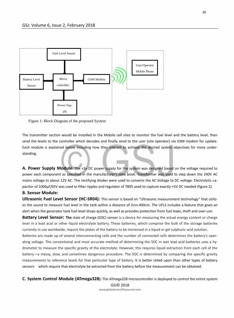
The proposed system hardware (transmitter’s side) design comprises of four modules namely fuel level & battery status
sensors, Microcontroller, Power supply, and GSM modem (figure 1).
37
Page 3
GSJ: Volume 6, Issue 2, February 2018
GSJ© 2018 www.globalscientificjournal.com
3.1: Transmitter Section
The transmitter section would be installed in the Mobile cell sites to monitor the fuel level and the battery level, then
send the levels to the controller which decodes and finally send to the user (site operator) via GSM modem for update.
Each module is explained below including how they interact to achieve the desired system objectives for more under-
standing.
A. Power Supply Module: The +5v DC power supply for the system was designed based on the voltage required to
power each component as specified in the manufacturer’s data book. Transformer was used to step down the 240V AC
mains voltage to about 12V AC. The rectifying diodes were used to converts the AC Voltage to DC voltage. Electrolytic ca-
pacitor of 1000µF/35V was used to filter ripples and regulator of 7805 used to capture exactly +5V DC needed (figure 2).
B. Sensor Module:
Ultrasonic Fuel Level Sensor (HC-SR04): This sensor is based on “Ultrasonic measurement technology” that utiliz-
es the sound to measure fuel level in the tank within a distance of 2cm-400cm. The UFLS includes a feature that gives an
alert when the generator tank fuel level drops quickly, as well as provides protection from fuel leaks, theft and over-use.
Battery Level Sensor: The state of charge (SOC) sensor is a device for measuring the actual energy content or charge
level in a lead acid or other liquid electrolyte battery. These batteries, which comprise the bulk of the storage batteries
currently in use worldwide, require the plates of the battery to be immersed in a liquid or gel sulphuric acid solution.
Batteries are made up of several interconnecting cells and the number of connected cells determines the battery's oper-
ating voltage. The conventional and most accurate method of determining the SOC in wet lead acid batteries uses a hy-
drometer to measure the specific gravity of the electrolyte. However, this requires liquid extraction from each cell of the
battery—a messy, slow, and sometimes dangerous procedure. The SOC is determined by comparing the specific gravity
measurements to reference levels for that particular type of battery. It is better relied upon than other types of battery
sensors which require that electrolyte be extracted from the battery before the measurement can be obtained.
C. System Control Module (ATmega328): The ATmega328 microcontroller is deployed to control the entire system
Battery Level
Sensor
Power Sup-
ply
Micro
controller:
GSM Modem
Fuel Level Sensor
User/Operator
Mobile Phone
Figure 1: Block Diagram of the proposed System
38
Page 4
GSJ: Volume 6, Issue 2, February 2018
GSJ© 2018 www.globalscientificjournal.com
performance because of its wonderful features as stated clearly in the manufacturer’s data sheet. The Arduino Uno is pro-
grammed to accept data from the two sensors, process and make proactive decisions, then send to GSM modem for
transmission (figure 2).
D GSM Modem Module (SIM900): This SIM900 delivers GSM/GPRS 850/900/1800/1900MHz performance for voice,
SMS, Data, and Fax in a small form factor and with low power consumption. It is deployed for wireless transmission of
sensor data to the site operator. The modem communicates with the microcontroller through ‘AT’ commands (figure 2).
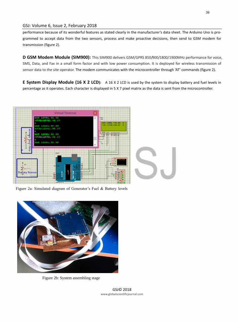
E System Display Module (16 X 2 LCD): A 16 X 2 LCD is used by the system to display battery and fuel levels in
percentage as it operates. Each character is displayed in 5 X 7 pixel matrix as the data is sent from the microcontroller.
Figure 2a: Simulated diagram of Generator’s Fuel & Battery levels
Remote monitoring system
Figure 2b: System assembling stage
39
Page 5
GSJ: Volume 6, Issue 2, February 2018
GSJ© 2018 www.globalscientificjournal.com
3.2 Receiver Section (Mobile Phone) The Cell site operator would receive an alert via his/her mobile phone concerning the status of the generator’s fuel level
and battery level (depending on the percentage usage like 20%, 40%, 60%, 80% etc. ) at an interval of time from all the
sites he/she would be managing.
3.3 System Algorithm The Microcontroller uses Algorithm to monitor and relay message to the site operator. The algorithm first initializes the
entire system; monitors the sensors and reads signals to determine the levels of the fuel and the battery. The Microcon-
troller takes decision based on the percentage usage of both concerned parameters. When the percentage usage drops to
80%, 60%, 40%, 20% etc., the system warns the site operator for necessary actions. The flow chart (figure 3) shows the
algorithm followed to carry out the function.
3.4 Multiple Cell Sites Setup
Yes No
o
Start
Send the data at intervals
to Operator
Get sensor data
Is data
critical?
Send a critical
alert
Keep logging
data
Figure 3: The system program Flow chart
40
Page 6
GSJ: Volume 6, Issue 2, February 2018
GSJ© 2018 www.globalscientificjournal.com
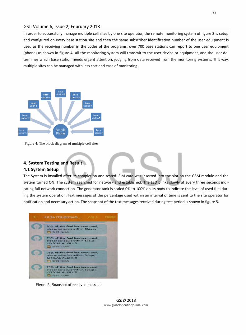
In order to successfully manage multiple cell sites by one site operator, the remote monitoring system of figure 2 is setup
and configured on every base station site and then the same subscriber identification number of the user equipment is
used as the receiving number in the codes of the programs, over 700 base stations can report to one user equipment
(phone) as shown in figure 4. All the monitoring system will transmit to the user device or equipment, and the user de-
termines which base station needs urgent attention, judging from data received from the monitoring systems. This way,
multiple sites can be managed with less cost and ease of monitoring.
4. System Testing and Result
4.1 System Setup The System is installed after its completion and tested. SIM card was inserted into the slot on the GSM module and the
system turned ON. The system searched for network and established. The LED blinks slowly at every three seconds indi-
cating full network connection. The generator tank is scaled 0% to 100% on its body to indicate the level of used fuel dur-
ing the system operation. Text messages of the percentage used within an interval of time is sent to the site operator for
notification and necessary action. The snapshot of the text messages received during test period is shown in figure 5.
Figure 4: The block diagram of multiple cell sites
Figure 5: Snapshot of received message
41
Page 7
GSJ: Volume 6, Issue 2, February 2018
GSJ© 2018 www.globalscientificjournal.com
4.2 System Data Logger Alert Message
a. Non Critical Message The non critical alert is the normal alert that is sent always when fuel and battaery percentage usage being monitored are
greater than the 15% set point (table 1). Figure 6a shows the non critical set point logging data alert displayed during the
test running period.
b. Critical Alert Message The critical alert message is the warning message sent to the cell site operator’s phone and other logging devices
only when the fuel and battery percentage usage is below or exactly at the set point of 15% (table 1).. Figure 6b
shows the data logger critical alert received during the test running period.
Table 1 shows the percentage set point for the system
Figure 6a: Non critical alert message in Percentage
Figure 6b: Critical alert message in Percentage
42
Page 8
GSJ: Volume 6, Issue 2, February 2018
GSJ© 2018 www.globalscientificjournal.com
4.3 System Operation The simulation of IoT Based battery and fuel levels monitoring system with SMS alert was done to showcase the
performance of the system. The battery and fuel levels were monitored by reading the voltage variations in the battery
strength and fuel level, mapped in analog form within the range (0-1023). This means that the sensors were able to
convert fuel level and battery strength sensed into voltage levels mapped in analog form between 0-1023 The 10bit
Analog to Digital Converter (ADC) converts sensor signals into its digital equivalent and sent to the microcontroller which
processed and then send to the display unit (in percentage).The discrete (digital) value taken and signalled at the following
percentage levels: 15 percent (critical value; attention needed), 20 percent, 40 percent, 60 percent, 80 percent. The
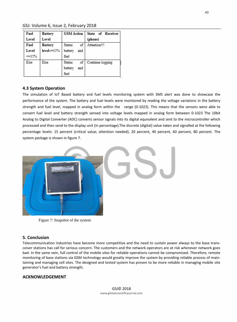
system package is shown in figure 7.
5. Conclusion Telecommunication industries have become more competitive and the need to sustain power always to the base trans-ceiver stations has call for serious concern. The customers and the network operators are at risk whenever network goes bad. In the same vein, full control of the mobile sites for reliable operations cannot be compromised. Therefore, remote monitoring of base stations via GSM technology would greatly improve the system by providing reliable process of main-taining and managing cell sites. The designed and tested system has proven to be more reliable in managing mobile site generator’s fuel and battery strength. ACKNOWLEDGEMENT
Figure 7: Snapshot of the system
43
Page 9
GSJ: Volume 6, Issue 2, February 2018
GSJ© 2018 www.globalscientificjournal.com
We would like to express our deepest appreciation to God for making this paper a success. Special thanks to our families for all their moral and financial support throughout the research work. Also our appreciation goes to SAP editors, for their commitment and quick response in attending to journal papers.
REFERENCES [1] Boopathi S., Jagadeeshraja M., Manivannan L., Dhanasu M. Smart.(2015),Generator Monitoring System in Industry Using Micro-
controller. American .Journal of Electrical Power and Energy Sytems.Vol.4,No.4,2015,pp..45-50.doi:10.11648/j.epes.20150404.13
[2] Anshu Shrivastava, Balkrishna Dwivedi , Deepak Parashar. (2013) “GSM Based Home Security System” international Journal Of
Emerging Trends In Electronics And Computer Science (IJETECS) Volume 2, Issue 4, April 2013.
[3] Subhani Sk. M.1, Sateesh G.N.V2, Chaitanya Ch.3 and PrakashBabu G.4 (2013) “Implementation of GSM Based Heart Rate
and ……Temperature Monitoring System”.
[4] BulliBabu R.,JonathanSoumith C.,Cherishma Sri Lakshmi T.& KeshavRao .R.(2015), GSM based Agriculture Monitoring and Control-
ling System.
[5] Soyoung Hwang and Donghui Yu (2012),“Remote Monitoring and Controlling .System Based on ZigBee Networks” International
Journal of Software Engineering and Its Applications Vol. 6, No. 3, July 2012.
*6+ Xu M., Fei Y., Zhao F., Zhu Q.(2009), “A remote medical monitoring system based .on GSM network”. Wireless Mobile and Computing
(CCWMC, 2009), IET .International Communication Conference, December
[7] Garcia J., (2011), “Integrated Off-Line Ballast for High Brightness LEDs with.Dimming Capability,” Circuits Syst., vol. 02, no. 04, pp.
338–351, 2011.
44


![Ultrasonic Based Distance Measurement System - News · PDF fileEE616 Electronic Design Lab Project Report, ... [2] K. J. Ayala, 8051 Microcontroller, ... GAIN AMPLIFIER ULTRASONIC](https://static.documents.pub/doc/80x56/5a700db87f8b9abb538b95a5/ultrasonic-based-distance-measurement-system-newswww8051projectsnetfilespublic133794617138097ft0reportpdfpdf.jpg)
