38
® David Tanis Technical Director EMEA 7 October 2009 When Data Centre Cabling Becomes Art
| Date post: | 20-Aug-2015 |
| Category: |
Technology |
| Upload: | ipexpo-online |
| View: | 1,584 times |
| Download: | 0 times |

®
David TanisTechnical Director EMEA7 October 2009
When Data Centre Cabling Becomes Art

®
Page 2
Data Centre TrendsData Centre Trends
Data Centre Consolidation Data Centre Expansion Merger / Acquisition
Technology Refresh/ Migration (18-36 months)
Server and SAN Virtualisation Blade server deployment Enhancing SAN connectivity architecture
New Data Centre Build - Greenfield Business Continuity/Disaster Recovery
®
Page 3
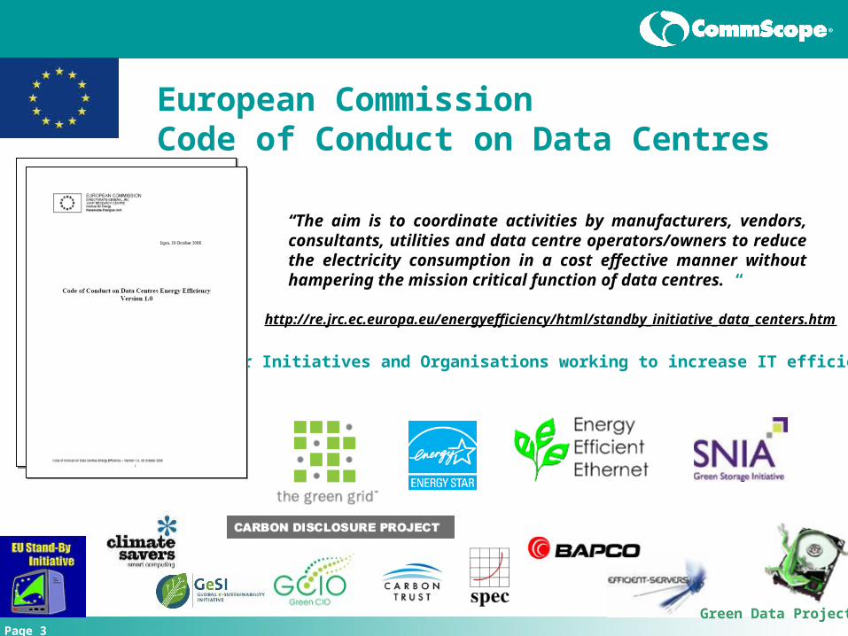
European CommissionCode of Conduct on Data Centres
http://re.jrc.ec.europa.eu/energyefficiency/html/standby_initiative_data_centers.htm
“The aim is to coordinate activities by manufacturers, vendors, consultants, utilities and data centre operators/owners to reduce the electricity consumption in a cost effective manner without hampering the mission critical function of data centres. “
Other Initiatives and Organisations working to increase IT efficiency
Green Data Project

®
Page 4
Data Centre Cabling Best Practices

®
Page 5
Cable Placement and Cable Placement and Thermal ManagementThermal Management For every 10°C increase above 21°C, mean time to failure (MTTF) for active
equipment is reduced by 50%
The average large data centre provides 2.7 times more cooling than necessary due to poor airflow management in racks and cabinets
In most data centres 60% of conditioned airflow bypasses data equipment air intakes
Cabling issues consistently ranked as a top contributor to poor cooling in data centres

®
Page 6
Hot Aisle
Cold Aisle
Hot Aisle
Communications Cabling
Raised Floor
Standards-Based Data Centre Cable RoutingStandards-Based Data Centre Cable Routing
®
Page 7
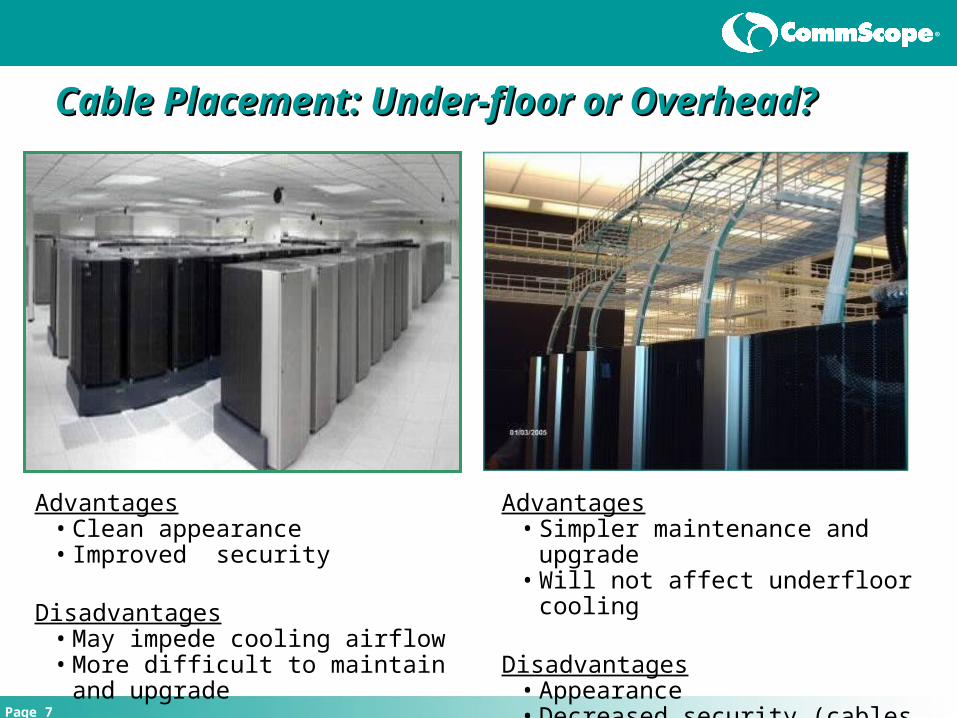
Cable Placement: Under-floor or Overhead?Cable Placement: Under-floor or Overhead?
Advantages• Clean appearance• Improved security
Disadvantages• May impede cooling airflow• More difficult to maintain and upgrade
Advantages• Simpler maintenance and upgrade• Will not affect underfloor cooling
Disadvantages• Appearance• Decreased security (cables exposed)

®
Page 8
Data Centre Cabling Standards
®
Page 9
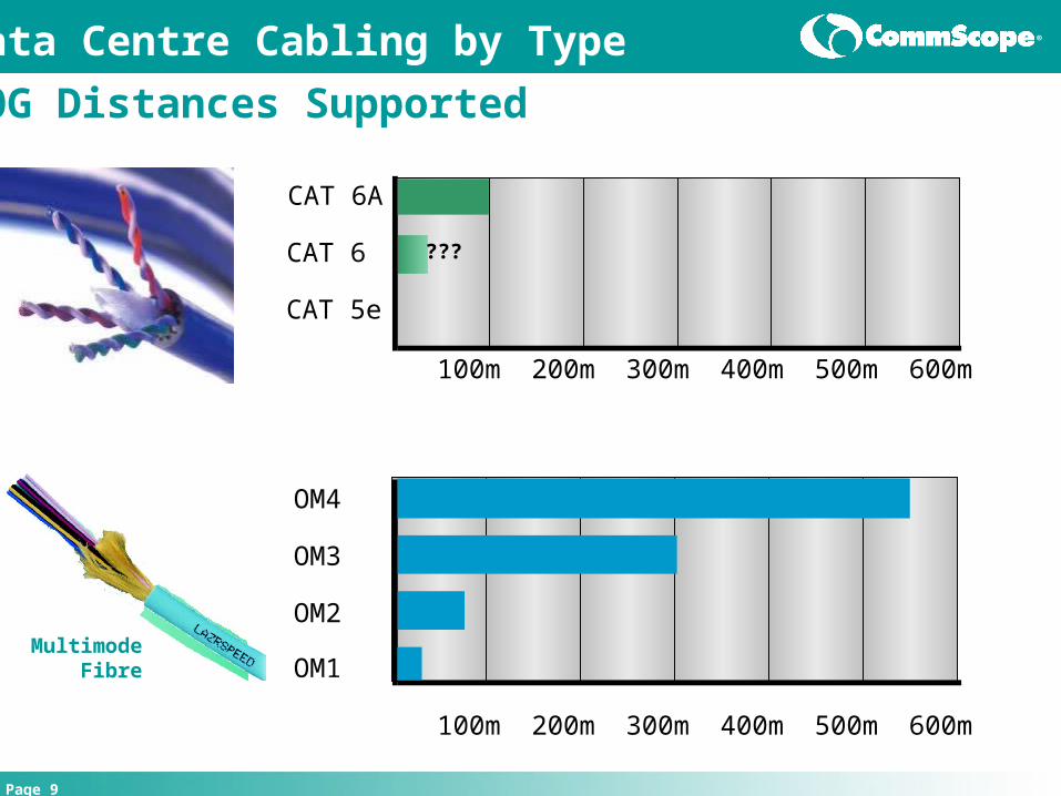
OM4
OM3
OM2
OM1
100m 200m 300m 400m 500m 600m
CAT 6A
CAT 6
CAT 5e
100m 200m 300m 400m 500m 600m
???
Data Centre Cabling by Type
10G Distances Supported
Multimode Fibre
®
Page 10
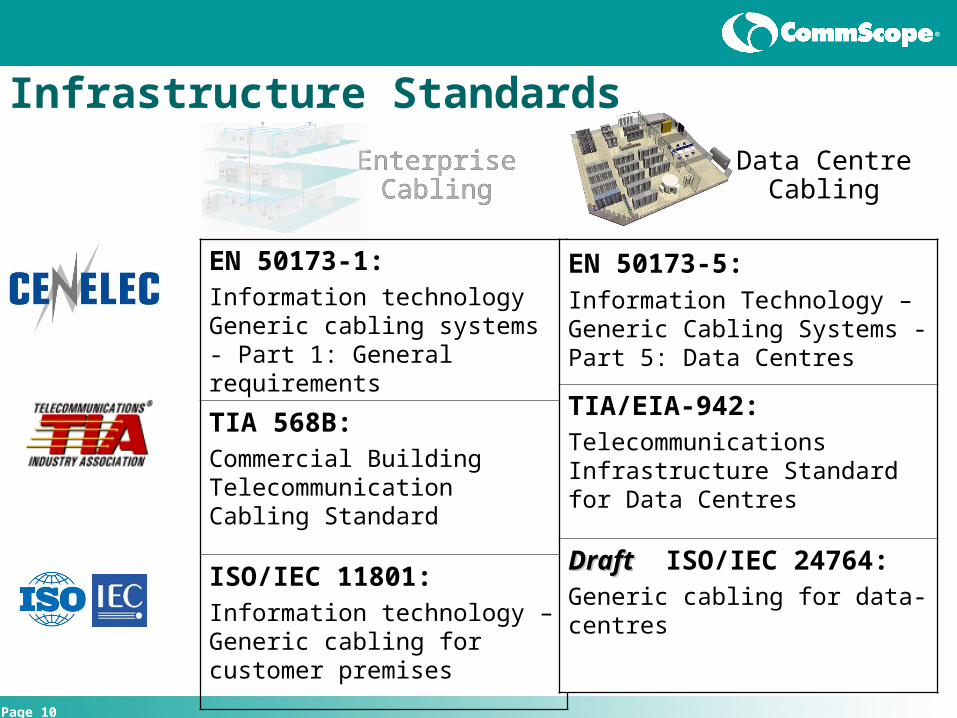
Infrastructure Standards
EnterpriseCabling
Data CentreCabling
EnterpriseCabling
EN 50173-1: Information technology Generic cabling systems - Part 1: General requirements
TIA 568B: Commercial Building Telecommunication Cabling Standard
ISO/IEC 11801: Information technology – Generic cabling for customer premises
EN 50173-5: Information Technology –Generic Cabling Systems - Part 5: Data Centres
TIA/EIA-942: Telecommunications Infrastructure Standard for Data Centres
DraftDraft ISO/IEC 24764: Generic cabling for data-centres

®
Page 11
Infrastructure Standards Infrastructure Standards for the Data Centrefor the Data Centre
Media
2007
Minimum Class E
OM3 recommended OS1
SFF (1-2 fibres) MPO (> 2 fibres)
EN 50173-5TIA/EIA-942
2005
Cat 6 recommended
OM3 recommended OS1
2009?
Class EA
OM3 recommended OS2
LC (1-2 fibres) MPO (> 2 fibres)
ISO 24764
Published
Copper
Fibre
Connector

®
Page 12
Basic Data Basic Data CentreCentre Topology Topology Source - TIA-942Source - TIA-942
Main Distribution Area
(Routers, backbone LAN/SAN switches, PBX)
Main Distribution Area
(Routers, backbone LAN/SAN switches, PBX)
Horiz Dist’n Area( LAN/SAN/KVM
switches)
Horiz Dist’n Area( LAN/SAN/KVM
switches)
Equip Dist’n Area(Rack/Cabinet)
Equip Dist’n Area(Rack/Cabinet)
Horiz Dist’n Area( LAN/SAN/KVM
switches)
Horiz Dist’n Area( LAN/SAN/KVM
switches)
Equip Dist’n Area(Rack/Cabinet)
Equip Dist’n Area(Rack/Cabinet)
Equip Dist’n Area(Rack/Cabinet)
Equip Dist’n Area(Rack/Cabinet)
Horiz Dist’n Area( LAN/SAN/KVM
switches)
Horiz Dist’n Area( LAN/SAN/KVM
switches)
Zone Dist AreaZone Dist Area
Entrance Room(Carrier Equip &
Demarcation)
Entrance Room(Carrier Equip &
Demarcation)
Access ProvidersAccess Providers
Offices, Operations Centre, Support
Rooms
Offices, Operations Centre, Support
Rooms
Telecom Room(Office & Operations
Centre LAN)
Telecom Room(Office & Operations
Centre LAN)
Backbone Cabling
Backbone Cabling
Horizontal CablingHorizontal CablingHorizontal Cabling
Horizontal Cabling
Horizontal Cabling
Backbone
Cabling
Computer Room

®
Page 13
Studies show that average usage rate of stand-alone servers is only around 20%
Virtualisation allows multiple applications to run on the same server
Provides better utilisation of servers, rack space AND power
Server VirtualisationServer VirtualisationDriving the Need for 10GDriving the Need for 10G
Uplink must be able to handle increased traffic load 10G cabling required!
Virtualisation Study:Annual Power and Cooling savings of €570 per virtualised application
Source:

®
Page 14
Internet selling prices 14/7/09
10G: Server Adapter Price Comparison10G: Server Adapter Price Comparison
Price:
10GBASE-T
£ 365
Distance: 100 meters
10GBASE-SR
£ 1,058
550 meters (OM4 Fibre)
10GBASE-CX4
£ 637
10 meters
®
Page 15
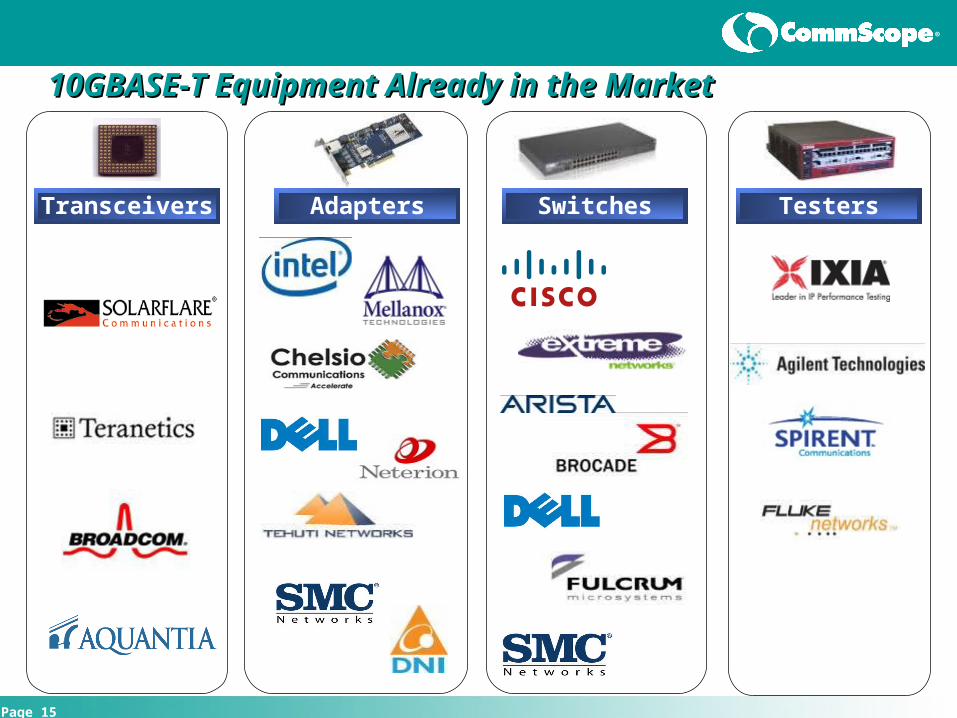
10GBASE-T Equipment Already in the Market 10GBASE-T Equipment Already in the Market
Transceivers Adapters Switches Testers
®
Page 16
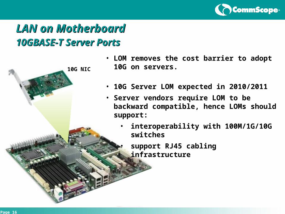
LAN on MotherboardLAN on Motherboard10GBASE-T Server Ports10GBASE-T Server Ports
• LOM removes the cost barrier to adopt 10G on servers.
• 10G Server LOM expected in 2010/2011
• Server vendors require LOM to be backward compatible, hence LOMs should support:
• interoperability with 100M/1G/10G switches
• support RJ45 cabling infrastructure
10G NIC

®
Page 17
Pre-Terminated Cabling for Data Centres Pre-Terminated Cabling for Data Centres
®
Page 18
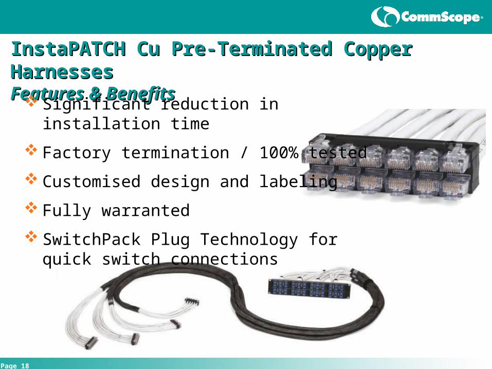
InstaPATCH Cu InstaPATCH Cu Pre-Terminated Copper HarnessesPre-Terminated Copper Harnesses Features & BenefitsFeatures & Benefits
Significant reduction in installation time
Factory termination / 100% tested
Customised design and labeling
Fully warranted
SwitchPack Plug Technology for quick switch connections

®
Page 19
erline
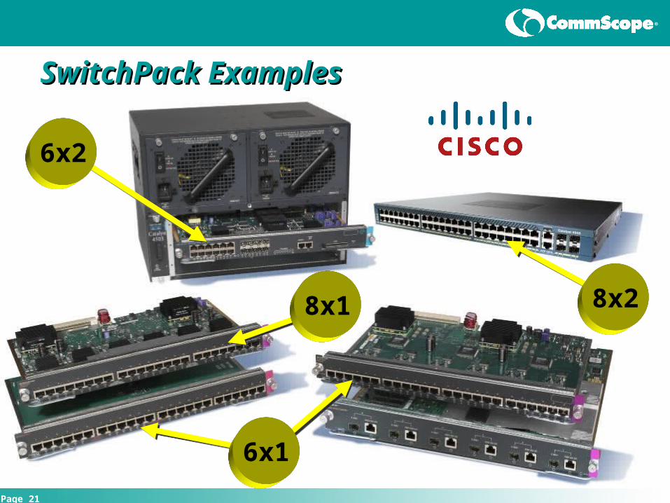
Switch Harness: SwitchPack to JackSwitch Harness: SwitchPack to Jack High-density Switchport to
Patch Panels– 6, 8, 12, 16-port versions– Cisco, HP, Foundry and
others– Cat6 and Cat6A
Switch EndSwitch End
®
Page 20
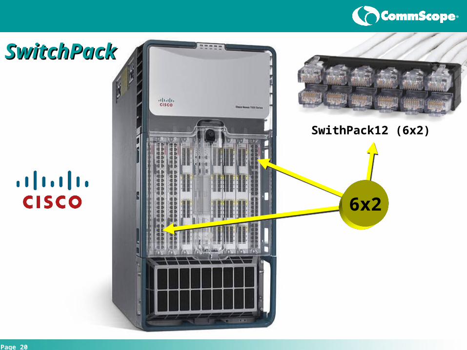
6x2
SwithPack12 (6x2)
SwitchPackSwitchPack
®
Page 21
SwitchPack ExamplesSwitchPack Examples
8x2
6x2
6x1
8x1

®
Page 22
From Elevation View to InstallationFrom Elevation View to Installation

®
Page 23
Pre-Terminated Fibre Solutions
Fibre Cables pre-terminated with MPO connector
Designed to length, fibre count and type
All cables and modules tested in factory
Installation time reduced significantly

®
Page 24
Fibre Array Cabling and the MPOFibre Array Cabling and the MPOIdeally Suited for Upgrade to Parallel TransmissionIdeally Suited for Upgrade to Parallel Transmission
MPO Connectors
Proven technology supporting serial transmission today
Compliant with TIA-568B.1 AD7 Array Polarity Addendum
Method B (InstaPATCH Plus) No polarity-correcting components
Supports 2-fiber connectivity and parallel applications
Recommended in upcoming standards revisions:
EN 50174-2: Cabling installation – Installation Planning and Practices
ISO/IEC 14763-2 Installation and Test

®
Page 25
Standard ProductsStandard Products
RS
-232
Link
10/100 Mb/s
Active CP
RS
-232
Link
10/100 Mb/s
Active CP
RS
-232
Link
10/100 Mb/s
Active CP
RS
-232
Link
10/100 Mb/s
Active CP
Array Patch Cords
1000G2 IPShelves
8 MPO AdapterPanels
InstaPATCH Trunk Cables
Fibre Patch Cords
1000G2 IPShelves
1000G2 IPShelves
InstaPATCH Plus DM2-24LC Modules
Cross Connect Director Rack

®
Page 26
High Density Installation becomes High Density Installation becomes unmanageable using jumpersunmanageable using jumpers
SAN Director
With InstaPATCH
®
40G and 100GbE40G and 100GbE
®
Page 28
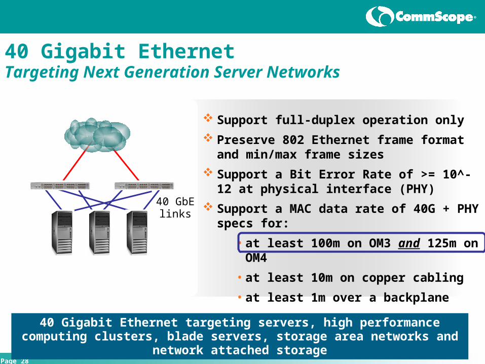
40 Gigabit Ethernet Targeting Next Generation Server Networks
40 GbE links
Support full-duplex operation only
Preserve 802 Ethernet frame format and min/max frame sizes
Support a Bit Error Rate of >= 10^-12 at physical interface (PHY)
Support a MAC data rate of 40G + PHY specs for:
• at least 100m on OM3 and 125m on OM4
• at least 10m on copper cabling
• at least 1m over a backplane
40 Gigabit Ethernet targeting servers, high performance computing clusters, blade servers, storage area networks and network attached storage

®
Page 29
40GbE: Baseline Draft Fibre Options40GbE: Baseline Draft Fibre Options
4-Lane ParallelPHY
40 Gigabit Media Independent Interface (XLGMII), 4 Lanes40 Gigabit Attachment Unit Interface (XLAUI), 4 Lanes
40 Gigabit MAC
MSA
4 CWDM~1310 nm 10 km
OS2PMD
40GBASE-LR4
LR4
CFP
4 Lane850 nm 100 m
OM3PMD
40GBASE-SR4
SR4
QSFPSNAP-12
®
Page 30
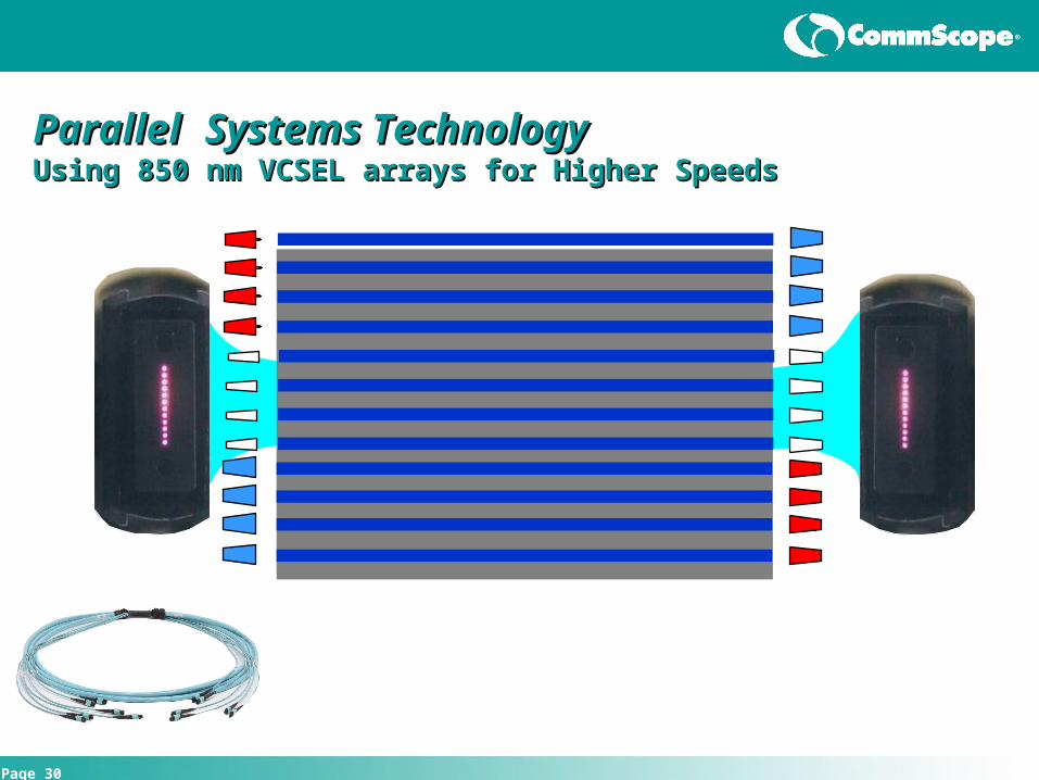
ParallelParallel Systems TechnologySystems Technology
Using 850 nm VCSEL arrays for Higher SpeedsUsing 850 nm VCSEL arrays for Higher Speeds

®
Page 31
Adding Intelligence to the Data CentreAdding Intelligence to the Data CentreiPatch System for Intelligent Infrastructure iPatch System for Intelligent Infrastructure ManagementManagement

®
Page 32
Why Consider Intelligent Infrastructure in the DC?Why Consider Intelligent Infrastructure in the DC?Meeting Today’s IT ChallengesMeeting Today’s IT Challenges
Pressure to Achieve More with Less…
Streamlining of Workflow Processes
Disaster Recovery and Fault Management
Data Centre Growth and Manageability
Regulatory, Compliance and Security
• Sarbanes-Oxley
• HIPAA
• ISO 17799 / ISO 27001
Best Practices Industry Standards
• CoBiT, ITIL, FCAPS, ISO 20000…

®
Page 33
Desktop User LAN Voice Server Application WAN OSI Layer 1
Collecting Data for the Configuration Collecting Data for the Configuration Management Database (CMDB)Management Database (CMDB)

®
Page 34
Convocation Hall to Rothman Centre path CH-Rothman
Location FROM eqipment # Cable # TO equipment
Rm. 142 USER-306 1A STPATCH 1B PAA-0134-01F-01PAA-0134-01F-01 1A 0134F-02B-01F-01(1) 13A F24-0134-02B-04
Rm. 272 F24-0134-02B-04 13B STPATCH 3B F24-0134-02B-01F24-0134-02B-01 3A 0135F-0134-03(3) 3A F24-0135-1BA-03
Rm. 124 F24-0135-1BA-03 3B STPATCH 37B F48-0135-1BA-01F48-0135-1BA-01 37A 0038F-0135-01(37) 37A F48-0038-1BA-01
Rm. 25A F48-0038-1BA-01 37B STPATCH 55B F96-0038-1BA-01F96-0038-1BA-01 55A 0038F-0088-01(7) 7A F24-0088-1BA-01
bsmt F24-0088-1BA-01 7B STPATCH 15B F96-0088-1BA-01F96-0088-1BA-01 15A 0088F-0103-01(15) 15A F96-0103-1BA-01
bsmt NEMA F96-0103-1BA-01 15B STPATCH 61B F96-0103-1BA-01F96-0103-1BA-01 61A 0104F-0103-01(13) 13A F96-0104-1BA-01
bsmt cage F96-0104-1BA-01 13B STPATCH 3B F24-0104-1BA-01F24-0104-1BA-01 3A 0104F-0132-01(3) 3A F24-0132-1BA-03
bsmt rm.14 F24-0132-1BA-03 3B STPATCH 5B F24-0132-1BA-01F24-0132-1BA-01 5A 0006F-0132-01(5) H5 F96-0006-01A-01
rm. 1069 F96-0006-01A-01 61B STPATCH 7B F24-0006-01A-01F24-0006-01A-01 7A 0006F-0033-01(7) 7A F24-0033-1BA-01
rm. 52 F24-0033-1BA-01 7B STPATCH 5B F96-0033-1BA-02F96-0033-1BA-02 5A 0033F-0073-03(5) 17A F96-0073-01A-01
rm. 129A F96-0073-01A-01 17B STPATCH 5B F96-0073-01A-01F96-0073-01A-01 5A 0073F-0078-03(5) 17A F96-0078-03A-02
machine rm. F96-0078-03A-02 17B STPATCH 11B F96-0078-03A-01F96-0078-03A-01 B3 0036F-0078-01(23) 11A F24-0036-GRA-01
Lockers F24-0036-GRA-01 11B STPATCH 65B F96-0036-GRA-01F96-0036-GRA-01 65A 0036F-0009-01(17) 17A F96-0009-1BA-04
The Hub!! F96-0009-1BA-04 17B STPATCH 3B F72-0009-1BA-01F72-0009-1BA-01 A3 0009F-0010-01(3) 15A F24-0010-1BA-01
rm. 3 F24-0010-1BA-01 15B STPATCH 1B F24-0010-1BA-04F24-0010-1BA-04 1A 0010F-A010-01(1) 1A PAA-A010-1BA-01
bsmt PAA-A010-1BA-01 1B STPATCH 1A PAA-A010-01A-01Stage PAA-A010-01A-01 1B STPATCH 1A USER-080
Best Case
• Excel spreadsheet or Cable Management Software
• Manually updated
• Reliance on technician for accuracy
• Not “real-time”
• Must be audited for accuracy
Worst Case
Mapping the Physical Layer without an Intelligent SystemMapping the Physical Layer without an Intelligent System

®
Page 35
Patch Cord ManagementPatch Cord ManagementThe “Spaghetti” ChallengeThe “Spaghetti” Challenge

®
Page 36
Switch
Server
iPatchProvides Physical Connectivity Map
ZDA
Logical ConnectionServer to Switch
®
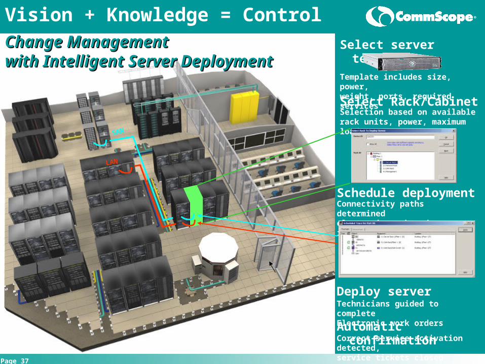
Page 37
Select server template
Vision + Knowledge = Control
Change ManagementChange Managementwith Intelligent Server Deploymentwith Intelligent Server Deployment
Template includes size, power,weight, ports, required services
Deploy serverTechnicians guided to completeElectronic work orders
Automatic confirmationCorrect service activation detected,service tickets closed
Schedule deploymentConnectivity paths determinedelectronic work orders issued
Select Rack/CabinetSelection based on availablerack units, power, maximum load
LAN
SAN

®
Page 38
Thank You


