92
15-601046 Issue 17a - (07 March 2011) H323 IP Telephone Installation IP Office

15-601046 Issue 17a - (07 March 2011)
H323 IP Telephone Installation
IP Office

H323 IP Telephone Installation Page 215-601046 Issue 17a (07 March 2011)IP Office
© 2011 AVAYA All Rights Reserved.
NoticesWhile reasonable efforts have been made to ensure that the information inthis document is complete and accurate at the time of printing, Avayaassumes no liability for any errors. Avaya reserves the right to make changesand corrections to the information in this document without the obligation tonotify any person or organization of such changes.
Documentation disclaimerAvaya shall not be responsible for any modifications, additions, or deletionsto the original published version of this documentation unless suchmodifications, additions, or deletions were performed by Avaya.
End User agree to indemnify and hold harmless Avaya, Avaya's agents,servants and employees against all claims, lawsuits, demands and judgmentsarising out of, or in connection with, subsequent modifications, additions ordeletions to this documentation, to the extent made by End User.
Link disclaimerAvaya is not responsible for the contents or reliability of any linked Web sitesreferenced within this site or documentation(s) provided by Avaya. Avaya isnot responsible for the accuracy of any information, statement or contentprovided on these sites and does not necessarily endorse the products,services, or information described or offered within them. Avaya does notguarantee that these links will work all the time and has no control over theavailability of the linked pages.
WarrantyAvaya provides a limited warranty on this product. Refer to your salesagreement to establish the terms of the limited warranty. In addition, Avaya’sstandard warranty language, as well as information regarding support for thisproduct, while under warranty, is available to Avaya customers and otherparties through the Avaya Support Web site: http://www.avaya.com/support.Please note that if you acquired the product from an authorized Avaya reselleroutside of the United States and Canada, the warranty is provided to you bysaid Avaya reseller and not by Avaya.
LicensesTHE SOFTWARE LICENSE TERMS AVAILABLE ON THE AVAYA WEBSITE,HTTP://SUPPORT.AVAYA.COM/LICENSEINFO/ ARE APPLICABLE TO ANYONEWHO DOWNLOADS, USES AND/OR INSTALLS AVAYA SOFTWARE,PURCHASED FROM AVAYA INC., ANY AVAYA AFFILIATE, OR AN AUTHORIZEDAVAYA RESELLER (AS APPLICABLE) UNDER A COMMERCIAL AGREEMENTWITH AVAYA OR AN AUTHORIZED AVAYA RESELLER. UNLESS OTHERWISEAGREED TO BY AVAYA IN WRITING, AVAYA DOES NOT EXTEND THISLICENSE IF THE SOFTWARE WAS OBTAINED FROM ANYONE OTHER THANAVAYA, AN AVAYA AFFILIATE OR AN AVAYA AUTHORIZED RESELLER, ANDAVAYA RESERVES THE RIGHT TO TAKE LEGAL ACTION AGAINST YOU ANDANYONE ELSE USING OR SELLING THE SOFTWARE WITHOUT A LICENSE. BYINSTALLING, DOWNLOADING OR USING THE SOFTWARE, OR AUTHORIZINGOTHERS TO DO SO, YOU, ON BEHALF OF YOURSELF AND THE ENTITY FORWHOM YOU ARE INSTALLING, DOWNLOADING OR USING THE SOFTWARE(HEREINAFTER REFERRED TO INTERCHANGEABLY AS “YOU” AND “ENDUSER”), AGREE TO THESE TERMS AND CONDITIONS AND CREATE ABINDING CONTRACT BETWEEN YOU AND AVAYA INC. OR THE APPLICABLEAVAYA AFFILIATE (“AVAYA”).
Avaya grants End User a license within the scope of the license typesdescribed below. The applicable number of licenses and units of capacity forwhich the license is granted will be one (1), unless a different number oflicenses or units of capacity is specified in the Documentation or othermaterials available to End User. "Designated Processor" means a singlestand-alone computing device. "Server" means a Designated Processor thathosts a software application to be accessed by multiple users. "Software"means the computer programs in object code, originally licensed by Avayaand ultimately utilized by End User, whether as stand-alone products orpre-installed on Hardware. "Hardware" means the standard hardwareoriginally sold by Avaya and ultimately utilized by End User.
License typesDesignated System(s) License (DS). End User may install and use each copyof the Software on only one Designated Processor, unless a different numberof Designated Processors is indicated in the Documentation or other materialsavailable to End User. Avaya may require the Designated Processor(s) to beidentified by type, serial number, feature key, location or other specificdesignation, or to be provided by End User to Avaya through electronic meansestablished by Avaya specifically for this purpose.
CopyrightExcept where expressly stated otherwise, no use should be made of materialson this site, the Documentation(s) and Product(s) provided by Avaya. Allcontent on this site, the documentation(s) and the product(s) provided byAvaya including the selection, arrangement and design of the content isowned either by Avaya or its licensors and is protected by copyright and otherintellectual property laws including the sui generis rights relating to theprotection of databases. You may not modify, copy, reproduce, republish,upload, post, transmit or distribute in any way any content, in whole or inpart, including any code and software. Unauthorized reproduction,transmission, dissemination, storage, and or use without the express writtenconsent of Avaya can be a criminal, as well as a civil, offense under theapplicable law.
Third Party Components Certain software programs or portions thereof included in the Product maycontain software distributed under third party agreements ("Third PartyComponents"), which may contain terms that expand or limit rights to usecertain portions of the Product ("Third Party Terms"). Information regardingdistributed Linux OS source code (for those Products that have distributed theLinux OS source code), and identifying the copyright holders of the ThirdParty Components and the Third Party Terms that apply to them is availableon the Avaya Support Web site: http://support.avaya.com/Copyright.
Preventing toll fraud"Toll fraud" is the unauthorized use of your telecommunications system by anunauthorized party (for example, a person who is not a corporate employee,agent, subcontractor, or is not working on your company's behalf). Be awarethat there can be a risk of toll fraud associated with your system and that, iftoll fraud occurs, it can result in substantial additional charges for yourtelecommunications services.
Avaya fraud interventionIf you suspect that you are being victimized by toll fraud and you needtechnical assistance or support, call Technical Service Center Toll FraudIntervention Hotline at +1-800-643-2353 for the United States and Canada.For additional support telephone numbers, see the Avaya Support Web site:http://support.avaya.comSuspected security vulnerabilities with Avaya products should be reported toAvaya by sending mail to: [email protected].
TrademarksAvaya and Aura are trademarks of Avaya, Inc.The trademarks, logos and service marks (“Marks”) displayed in this site, thedocumentation(s) and product(s) provided by Avaya are the registered orunregistered Marks of Avaya, its affiliates, or other third parties. Users arenot permitted to use such Marks without prior written consent from Avaya orsuch third party which may own the Mark. Nothing contained in this site, thedocumentation(s) and product(s) should be construed as granting, byimplication, estoppel, or otherwise, any license or right in and to the Markswithout the express written permission of Avaya or the applicable third party.Avaya is a registered trademark of Avaya Inc. All non-Avaya trademarks arethe property of their respective owners.
Downloading documentsFor the most current versions of documentation, see the Avaya Support Website: http://www.avaya.com/support
Contact Avaya SupportAvaya provides a telephone number for you to use to report problems or toask questions about your product. The support telephone number is1-800-242-2121 in the United States. For additional support telephonenumbers, see the Avaya Web site: http://www.avaya.com/support
H323 IP Telephone Installation Page 315-601046 Issue 17a (07 March 2011)IP Office
Contents
ContentsIP Office H323 IP Phones1.
..................................................................... 81.1 Supported Phones
..................................................................... 91.2 System Capacity
..................................................................... 101.3 Phone Firmware
..................................................................... 111.4 Simple Installation
..................................................................... 121.5 Installation Requirements
..................................................................... 131.6 Licenses
..................................................................... 141.7 Network Assessment
..................................................................... 151.8 Voice Compression
..................................................................... 171.9 QoS
..................................................................... 171.10 Potential VoIP Problems
..................................................................... 181.11 User PC Connection
..................................................................... 191.12 Power Supply Options
..................................................................... 211.13 File Server Options
..................................................................... 221.14 File Auto Generation
..................................................................... 231.15 Control Unit Memory Card
Installation2...................................................................... 282.1 Adding Licenses
..................................................................... 292.2 Creating/Editing the Settings File
..................................................................... 312.3 Manually Creating Extensions
..................................................................... 322.4 Phone Connection
..................................................................... 332.5 Static Address Installation
..................................................................... 342.6 Phone Registration
..................................................................... 352.7 Extension & User Setup
..................................................................... 352.8 Phone Security
..................................................................... 362.9 Backup Restore
..................................................................... 392.10 Listing Registered Phones
..................................................................... 402.11 Error Messages
Other Installation Options3...................................................................... 423.1 VPN Remote Phones
..................................................................... 453.2 VLAN and IP Phones
Static Administration Options4...................................................................... 534.1 QOS Option Settings
..................................................................... 534.2 Secondary Ethernet (Hub)/IR InterfaceEnable/Disable
..................................................................... 544.3 View Details
..................................................................... 554.4 Self-Test Procedure
..................................................................... 564.5 Resetting a Phone
..................................................................... 574.6 Site Specific Option Number
..................................................................... 584.7 Automatic Gain Control
Restart Scenarios5...................................................................... 615.1 Boot File Needs Upgrading
..................................................................... 615.2 No Application File or Application File NeedsUpgrading
..................................................................... 615.3 Correct Boot File and Application File AlreadyLoaded
Infrared Dialling6...................................................................... 656.1 Enabling the IR Port
..................................................................... 656.2 Dialling Phone Numbers
..................................................................... 666.3 Beaming Files During a Call
Alternate DHCP Server Setup7.
..................................................................... 697.1 Using a Windows DHCP Server
..................................................................... 727.2 Alternate Options
WML Server Setup8...................................................................... 758.1 Testing 4620 WML Browsing Using Xitami
..................................................................... 778.2 Setting the Home Page
..................................................................... 788.3 Apache Web Server WML Configuration
..................................................................... 788.4 Microsoft IIS Web Server WML Configuration
..................................................................... 798.5 Open URL Entry
...............................................................................81Index


H323 IP Telephone Installation Page 515-601046 Issue 17a (07 March 2011)IP Office
IP Office H323 IP Phones
Chapter 1.


H323 IP Telephone Installation Page 715-601046 Issue 17a (07 March 2011)IP Office
IP Office H323 IP Phones:
1. IP Office H323 IP PhonesThis documentation provides notes for the installation of supported Avaya 1600, 4600, 5600 and 9600 H323 IP phonesonto IP Office phone systems. It should be used in conjunction with the existing installation documentation for those seriesof phones, especially the following:
· 9600 Series IP Telephones Administrator Guide (16-300698)
· 4600 Series IP Telephone LAN Administrator Guide (555-233-507).
· 1600 Series IP Telephones Administrators Guide (16-601443).
· DHCP versus Static IP InstallationThough static IP installation of H323 IP phones is possible, installation using DHCP is strongly recommended. Theuse of DHCP eases both the installation process and future maintenance and administration. For static installations,following a boot file upgrade, all static address settings are lost and must be re-entered.
· Network AssessmentHigh quality voice transmission across an IP network requires careful assessment of many factors. Therefore:
· We strongly recommend that IP phone installation is only done by installers with VoIP experience.
· The whole customer network must be assessed for its suitability for VoIP, before installation. Avaya may refuseto support any installation where the results of a network assessment cannot be supplied. See NetworkAssessment for further details.
8
14

H323 IP Telephone Installation Page 815-601046 Issue 17a (07 March 2011)IP Office
1.1 Supported PhonesThis documentation provides installation notes for the following Avaya IP phone supported by IP Office. Other Avaya IPphones, for example 3600 Series and IP DECT are covered by separate installation documentation.
H323 IPPhones
SupportedModels
802.3af PoEClass
PC Port IP OfficeCoreSoftware
Class Idle
1600Series
1603 2 4.4W – 4.2 Q4 2008+.
1603SW 2 4.4W
1608 2 3.7W
1616 2 2.7W
4600Series
4601 2 3.5W – 3.0+
4602 1 – – 2.1+.
4602SW 2 3.5W
4606 0 4.1W Up to 3.2.
4610SW[1] 2 4.0W 3.0+.
4612 0 4.1W Up to 3.2.
4620 3 4.0W – 2.0+.
4620SW 2 –
4621SW[1] 2 5.75W 3.0+.
4624 0 4.1W Up to 3.2.
4625 3 6.45W 3.2+
5600Series
5601 2 3.5W – 3.0+.
5602 1 – –
5602SW 2 4.1W
5610SW[1] 2 3.1W
5620 3 3.6W
5621SW[1] 2 – 3.2+.
9600Series
9620L 1 2.0W 6.0+
9620C 2 3.9W
9630G 2 4.6W
9640 2 3.9W
9640G 2 3.9W
9650 2 4.7W
9650C 2 3.7W
9608 1 2.08W 6.1+
9611G 1 3.12W
9621G 2 3.49W
9641G 2 3.44W
1.VPNremote Support These phones can also be used with VPNremote firmware.
2.1603/1603SW These phones require a PoE Splitter unit in order to user PoE.

H323 IP Telephone Installation Page 915-601046 Issue 17a (07 March 2011)IP Office
IP Office H323 IP Phones: Supported Phones
1.2 System CapacitySystem capacity can be separated into two aspects; the number of configurable phone extensions and the number ofsimultaneous IP phone calls.
Extension CapacityThe maximum number of H323 IP phones supported by an IP Office system is based on that system's maximum capacityfor extensions of any type as listed in the table below. To find the capacity for IP phones remove the number of physicalnon-IP extensions installed on the system, ie. extension ports on the IP Office control unit and any external expansionmodules.
IP Office Unit MaximumExtensions
Maximum VCM Channels
IP406 V2 190 30
IP412 360 60
IP500 384 128
IP500 V2 384 148
Call CapacityThere are a number of situations where the IP Office system needs to provide a voice compression channel in order for anIP phone to make calls. These channels are provided by Voice Compression Modules (VCMs) installed in the IP Officesystem. The number of VCM channels required and how long the channel is required will depend on a number of factors.For further details see Voice Compression .
A simple summary is:
· A VCM channel is required during call setup.
· The VCM channel is released if the call is to/from another IP device using the same compression codec (thesupported VCM codecs are G711, G729 and G723a).
· The VCM channel is used for the duration of the call when the call is to/from/via a non-IP device (extension or trunkline).
· It should be remembered that VCM channels are also used for calls from non-IP devices to IP lines if those areconfigured in the IP Office system (IP, SIP and SES lines).
· Calls from IP phones to the IP Office voicemail server use a VCM channel.
· Note that on Small Office Edition systems with Embedded Voicemail, an additional channel is used for every callto voicemail.
15

H323 IP Telephone Installation Page 1015-601046 Issue 17a (07 March 2011)IP Office
1.3 Phone FirmwareThe firmware in Avaya IP phones is upgradeable and different releases of firmware are made available via the Avayasupport website. However H323 IP phones used on an IP Office system must only use the IP Phone software supplied withthe IP Office Manager application. Other versions of IP Phone software may not have been tested with IP Office and soshould not be used unless IP Office support is specifically mentioned in their accompanying documentation.
The phone firmware files are installed as part of the IP Office Manager application and are found in the applicationsinstallation directory. By default this is c:\Program Files\Avaya\IP Office\Manager.
For IP Office 4.2+, they firmware files are also available on the IP Office Administrator Applications CD from which IPOffice Manager is installed. The files are located in the \program files\Avaya\IP Office\Manager folder of theinstallation files. This makes it easier to locate all the files needed for IP phone installation though it also includes the .binfiles used for IP Office control and external expansion units.

H323 IP Telephone Installation Page 1115-601046 Issue 17a (07 March 2011)IP Office
IP Office H323 IP Phones: Phone Firmware
1.4 Simple InstallationThe diagram below shows a simple installation scenario that can be supported by all IP Office systems running IP OfficeRelease 6+.
This type of installation uses the following equipment:
· IP Office The IP Office control unit is performing a number of roles for the phones:
· DHCP Server The IP Office unit is acting as the DHCP server for the Avaya IP phones. Key settings such as the file serveraddress are entered into the IP Office configuration and then provided to the phones in addition to their IPaddress.The IP Office DHCP server can be configured to provide DHCP addresses only in response to requestsfrom Avaya IP phones. This allows an alternate DHCP server to be used for other devices that use DHCP.
· The IP Office control unit can provide DHCP support for up to 272 phones. Alternatively a separate DHCPserver can be used.
· H323 GatekeeperIP phones require an H323 gatekeeper to which they register. The gatekeeper then controls connecting calls tothe phone. In this scenario the IP Office control unit acts as the H323 Gatekeeper.
· File ServerDuring installation the IP phones need to download software and settings files for a file server. If the IP Officecontrol unit is fitted with a memory card (mandatory on IP500 v2 control units), that card can be used as thefile source.
· The IP Office control unit with memory card can act as the file server for up to 50 phones. Alternatively a3rd-party HTTP server can be used.
· The IP Office control unit with a memory card is not supported as a file server for 9608, 9621 and 9641phones. This also applies to using the IP Office Manager application for TFTP-HTTP relay. These phones areonly supported when using a 3-part HTTP file server for firmware.
· Switch The IP Office control units have limited numbers of LAN connection ports. They are intended to be connected to aLAN switch with port capacity for the customers network equipment.
· Power Supplies Each H323 IP phone requires a power supply.
· Individual Power Supply UnitsAn individual power supply unit can be used with each phone. This will require a power supply socket at eachphone location. Note that for phones using a button module add-on, for example a EU24 or BM32, an individualpower supply unit is a requirement.
· Power over Ethernet SupplyMost Avaya IP phones can be powered from an 802.3af Power over Ethernet (PoE) power supply. The IP Officesystem does not provide PoE ports so a separate PoE switch or PoE injector devices will be required to power aphone using PoE.

H323 IP Telephone Installation Page 1215-601046 Issue 17a (07 March 2011)IP Office
1.5 Installation RequirementsTo install an IP phone on IP Office, the following items are required:
· o Extension Number and User DetailsA full listing of the planned extension number and user name details is required. The planned extension numbermust be unused and is requested by the phone during installation.
· o Power SuppliesEach phone requires a power supply. Avaya IP phones do not draw power from the IP Office. A number of optionsexist for how power is supplied to the phones. See Power Supply Options .
· o LAN SocketAn RJ45 Ethernet LAN connection point is required for each phone.
· o Category 5 CablingAll LAN cables and LAN cable infrastructure used with H323 IP phones should use CAT5 cabling. Existing CAT3cabling may be used but will be limited to 10Mbps (maximum).
· o LAN CablesCheck that an RJ45 LAN cable has been supplied with the IP phone for connection to the power supply unit. You willalso need an additional RJ45 LAN cable for connection from the power unit to the customer LAN.
· A further RJ45 LAN cable can be used to connect the user's PC to the LAN via the IP phone [not supported on4601, 4602, 5601 and 5602 H323 IP phones].
· o Voice Compression ChannelsThe IP Office Unit must have voice compression channels installed. Channels are required during the connection ifcalls involving IP phones and may also be required during the call. See Voice Compression Channels for fulldetails.
· For Small Office Edition units, either 3 or 16 voice compression channels are pre-built into the unit.
· For IP400 control units, voice compression channels are provided by fitting a Voice Compression Module .
· For IP500 control units, channels are installed using a IP500 VCM base card and licenses or using IP400 VCMmodules on an IP500 Legacy Card.
· o DHCP ServerThe IP Office Unit can perform this role for up to 5 IP phone devices. If another DHCP server already exists, thismay be able to do DHCP for the H323 IP phones, see Alternate DHCP Servers . Static IP addressing can also beused, if required, but is not recommended.
· For IP500 IP Office 4.2+ systems, up to 272 IP phones are supported using the IP Office Manager.
· o HTTP/TFTP File ServerA PC running the IP Office Manager application can perform this role for up to 5 H323 IP phones. An IP Officecontrol unit with a memory card can use that memory card as the source for up to 50 phones. Otherwise analternate HTTP file server is required.
· The IP Office control unit with a memory card is not supported as a file server for 9608, 9621 and 9641phones. This also applies to using the IP Office Manager application for TFTP-HTTP relay. These phones areonly supported when using a 3-part HTTP file server for firmware.
· o H323 GatekeeperThe IP Office Unit performs this role.
· o IP Office Manager PCA PC running Manager is required for IP Office Unit configuration changes. This PC should have a static IP address.
· o IP Telephone SoftwareThe software for IP phone installation is installed into the IP Office Manager program folder during Managerinstallation.
· o Licence KeysFor IP Office Release 6, licenses Avaya IP Endpoint licenses are required on IP500 and IP500 V2 systems. Refer toLicenses.
19
15
15
68

H323 IP Telephone Installation Page 1315-601046 Issue 17a (07 March 2011)IP Office
IP Office H323 IP Phones: Installation Requirements
1.6 LicensesThe following licensing rules apply to the support of Avaya H323 IP phones on IP Office Release 6 systems.
IP500 and IP500 V2 IP Office SystemsOn IP500 and IP500 V2 systems, Avaya IP Endpoint license are these licenses are required for Avaya H323 IP phones.This includes all 1600, 4600, 5600, 9600, IP DECT, DECT R4, T3 IP, Spectralink and VPN phones supported by IP OfficeRelease 6.
· The system will automatically license 12 Avaya IP phones for each IP500 VCM 32 or VCM 64 card installed in thesystem without requiring additional licenses to be added to the configuration.
· Additional Avaya IP phones are licensed either by the addition of Avaya IP Endpoints licenses above or theconversion of legacy IP500 VCM Channels licenses to Channel Migration licenses (see below).
· By default licenses are consumed by each Avaya IP phone that registers with the IP Office in the order that theyregister. The license is released if the phone unregisters. However, it is possible to reserve a license for particularphones in order to ensure that they phones always obtain a license. This is done through the Reserve Avaya IPEndpoint Licence setting of each IP extension.
· Avaya IP phones without a license will still be able to register but will be limited to making emergency calls only(Dial Emergency short code calls). The associated user will be treated as if logged off and the phone will display "No license available". If a license becomes available, it will be assigned to any unlicensed DECT handsets first andthen to any other unlicensed Avaya IP phone in the order that the phones registered.
· For existing IP500 systems being upgraded to IP Office Release 6, the existing VCM channels and IP500 VCMChannels license are treated as follows:
· For each IP400 VCM card installed in the system, each VCM channel supported by the card allows support for 3Avaya IP phones.
· For each IP500 VCM32 and IP500 VCM64 card installed in the system, the 4 unlicensed VCM channelspreviously provided by each card are converted to allow unlicensed support of 12 Avaya IP phones.
· For each legacy IP500 VCM Channels license, the license are converted Channel Migration licensessupporting 3 Avaya IP phones. See the Channel Migration license below.
· The IP500 VCM 32 and IP500 VCM 64 cards will provide their full capacity of VCM channels, ie. providing up to32 or 64 channels depending on the card type and the codecs being used.
Other IP Office SystemsOn other IP Office systems, licenses are only required for phones using VPNremote firmware.

H323 IP Telephone Installation Page 1415-601046 Issue 17a (07 March 2011)IP Office
1.7 Network Assessment· WARNING: A Network Assessment is Mandatory
When installing H323 IP phones on an IP Office system, it is assumed by Avaya that a network assessment hasbeen performed. If a support issue is escalated to Avaya, Avaya may request to see the results of the networkassessment and may refuse to provide support if a suitable network assessment was not performed.
Current technology allows optimum network configurations to deliver VoIP with voice quality close to that of the publicphone network. However, few networks are optimum and so care should be taken assessing the VoIP quality achievableacross a customer network.
Not every network is able to carry voice transmissions. Some data networks have insufficient capacity for voice traffic orhave data peaks that will impact voice traffic on occasion. In addition, the usual history of growing and developingnetworks by integrating products from many vendors makes it necessary to test all the network components forcompatibility with VoIP traffic.
A network assessment should include a determination of the following:
· A network audit to review existing equipment and evaluate its capabilities, including its ability to meet both currentand planned voice and data needs.
· A determination of network objectives, including the dominant traffic type, choice of technologies and setting voicequality objectives.
· The assessment should leave you confident that the network will have the capacity for the foreseen data and voicetraffic, and can support H323, DHCP, TFTP and jitter buffers in H323 applications.
The network assessment targets are:
· Latency: Less than 180ms for good quality. Less than 80ms for toll quality. This is the measurement of packet transfer time in one direction. The range 80ms to 180ms is generally acceptable.Note that the different audio codecs used each impose a fixed delay caused by the codec conversion as follows:
· G711: 20ms.
· G723a: 80ms.
· G729: 40ms.
· Packet Loss: Less than 3% for good quality. Less than 1% for toll quality.Excessive packet loss will be audible as clipped words and may also cause call setup delays.
· Jitter: Less than 20ms. Jitter is a measure of the variance in the time for different packets in the same call to reach their destination.Excessive jitter will become audible as echo.
· Duration: Monitor statistics once every minute for a full week.The network assessment must include normal hours of business operation.

H323 IP Telephone Installation Page 1515-601046 Issue 17a (07 March 2011)IP Office
IP Office H323 IP Phones: Network Assessment
1.8 Voice CompressionCalls to and from IP devices can require conversion to the audio codec format being used by the IP device. For IP Officesystems this conversion is done by voice compression channels. These support the common IP audio codecs G711, G723and G729a.
For IP400 control units channels can be added by fitting IP400 Voice Compression Modules (VCMs). For the IP500 controlunits, channels can be added using IP500 VCM cards, IP500 Combination Cards and or IP400 Voice Compression Modules.
The voice compression channels are used as follows:
Call Type Voice Compression Channel Usage
IP Device to Non-IPDevice
These calls require a voice compression channel for the duration of the call. If no channel isavailable, busy indication is returned to the caller.
IP Device to IP Device Call progress tones (for example dial tone, secondary dial tone, etc) do not require voicecompression channels with the following exceptions:
· Short code confirmation, ARS camp on and account code entry tones require a voicecompression channel.
· Devices using G723 require a voice compression channel for all tones except callwaiting.
When a call is connected:
· If the IP devices use the same audio codec no voice compression channel is used.
· If the devices use differing audio codecs, a voice compression channel is required foreach.
Non-IP Device to Non-IP Device
No voice compression channels are required.
Music on Hold This is provided from the IP Office's TDM bus and therefore requires a voice compressionchannel when played to an IP device.
Conference Resourcesand IP Devices
Conferencing resources are managed by the conference chip which is on the IP Office's TDMbus. Therefore, a voice compression channel is required for each IP device involved in aconference. This includes services that use conference resources such as call listen, intrusion,call recording and silent monitoring.
Page Calls to IP Device IP Office 4.0 and higher only uses G729a for page calls, therefore only requiring one channelbut also only supporting pages to G729a capable devices.
Voicemail Services andIP Devices
Calls to the IP Office voicemail servers are treated as data calls from the TDM bus. Thereforecalls from an IP device to voicemail require a voice compression channel.
Fax Calls These are voice calls but with a slightly wider frequency range than spoken voice calls. IPOffice only supports fax across IP between IP Office systems with the Fax Transport optionselected. It does not currently support T38.
T38 Fax Calls IP Office 5.0+ supports T38 fax on SIP trunks and SIP extensions. Each T38 fax call uses aVCM channel.
Within a Small Community Network, a T38 fax call can be converted to a call across an H323SCN lines using the IP Office Fax Transport Support protocol. This conversion uses 2 VCMchannels.
In order use T38 Fax connection, the Equipment Classification of an analog extensionconnected to a fax machine can be set Fax Machine. Additionally, a new short code featureDial Fax is available.
Note: T3 IP devices must be configured to 20ms packet size for the above conditions to apply. If left configured for 10mspacket size, a voice compression channel is needed for all tones and for non-direct media calls.

H323 IP Telephone Installation Page 1615-601046 Issue 17a (07 March 2011)IP Office
Measuring Channel UsageThe IP Office System Status Application can be used to display voice compression channel usage. Within the Resourcessection it displays the number of channel in use. It also displays how often there have been insufficient channels availableand the last time such an event occurred.
The IP500 VCM cards, the level of channel usage is also indicated by the LEDs (1 to 8) on the front of the IP500 VCMcard.
Installing VCM CardsRefer to the IP Office Installation manual.

H323 IP Telephone Installation Page 1715-601046 Issue 17a (07 March 2011)IP Office
IP Office H323 IP Phones: Voice Compression
1.9 QoSWhen transporting voice over low speed links it is possible for normal data packets (1500 byte packets) to prevent ordelay voice packets (typically 67 or 31 bytes) from getting across the link. This can cause unacceptable speech quality.
Therefore, it is vital that all traffic routers and switches in the network to have some form of Quality of Service (QoS)mechanism. QoS routers are essential to ensure low speech latency and to maintain sufficient audible quality.
IP Office supports the DiffServ (RFC2474) QoS mechanism. This is based upon using a Type of Service (ToS) field in the IPpacket header. On its WAN interfaces, IP Office uses this to prioritize voice and voice signalling packets. It also fragmentslarge data packets and, where supported, provides VoIP header compression to minimize the WAN overhead.
Note
· IP Office does not perform QoS for its Ethernet ports including the WAN Ethernet port on the Small Office Edition.
1.10 Potential VoIP ProblemsIt is likely that any fault on a network, regardless of its cause, will initially show up as a degradation in the quality of VoIPoperation. This is regardless of whether the fault is with the VoIP telephony equipment. Therefore, by installing a VoIPsolution, you must be aware that you will become the first point of call for diagnosing and assessing all potential customernetwork issues.
Potential Problems
· End-to-End Matching StandardsVoIP depends upon the support and selection of the same voice compression, header compression and QoSstandards throughout all stages of the calls routing. The start and end points must be using the same compressionmethods. All intermediate points must support DiffServ QoS.
· Avoid HubsHubs introduce echo and congestion points. If the customer network requires LAN connections beyond the capacityof the IP Office Unit itself, Ethernet switches should be used. Even if this is not the case, Ethernet switches arerecommended as they allow traffic prioritization to be implemented for VoIP devices and for other device such asthe Voicemail Server PC.
· Power Supply Conditioning, Protection and BackupTraditional phone systems provide power to all their attached phone devices from a single source. In a VoIPinstallation, the same care and concern that goes into providing power conditioning, protection and backup to thecentral phone system, must now be applied to all devices on the IP network.
· MulticastingIn a data only network, it is possible for an incorrectly installed printer or hub card to multicast traffic without thatfault being immediately identified. On a VoIP network incorrect multicasting will quickly affect VoIP calls andfeatures.
· Duplicate IP AddressingDuplicate addresses is a frequent issue.
· Excessive UtilizationA workstation that constantly transmits high traffic levels can flood a network, causing VoIP service to disappear.
· Network AccessAn IP network is much more open to users connecting a new device or installing software on existing devices thatthen impacts on VoIP.
· Cabling ConnectionsTechnically VoIP can (bandwidth allowing) be run across any IP network connection. In practice, Cat5 cabling isessential.

H323 IP Telephone Installation Page 1815-601046 Issue 17a (07 March 2011)IP Office
1.11 User PC ConnectionTo simplify the number of LAN connections from the user's desk, it is possible to route their PC Ethernet LAN cable viasome H323 IP phones. The LAN cable should be connected from the PC to the socket with a PC symbol ( ) at the back ofthe IP phone. The PC's network configuration does not need to be altered from that which it previously used for directconnection to the LAN.
Except for phones with a G suffix, this port supports 10/100Mbps ethernet connections. Phones with a G suffix alsosupport 1000Mbps Gigabit connections. For other phones a separate Gigabit Adapter (SAP 700416985) must be used. Thisdevice splits the data and voice traffic before it reaches the phone, providing a 10/100Mbps output for the phone and a10/100/1000Mbps output for the PC. The adapter is powered from the phone's existing PoE supply or 1151 type powersupply unit. Refer to the "Gigabit Ethernet Adapter Installation and Safety Instructions" (16-601543).

H323 IP Telephone Installation Page 1915-601046 Issue 17a (07 March 2011)IP Office
IP Office H323 IP Phones: User PC Connection
1.12 Power Supply OptionsEach H323 IP phone requires a power supply. They do not draw power from the IP Office phone system. Listed below arethe power supply options that can be used.
Spare Wire Power OptionsThe following power supplies use the normally unused pin 7 & 8 connections in the CAT3 or CAT5 network cable. This isreferred to as "spare wire" or "mid-span" power supply units. They can be used with 4600 Series and 5600 Series IPphones.
· Avaya 1151D1 Power Supply Unit (PSU)A power supply unit for a single IP phone. Has a LINE port for the LAN cable from the IP Office, and a PHONE portfor the LAN cable to the IP phone. Power into the PSU requires a 90 to 264V AC, 47 to 63HZ mains supply. A greenLED indicates when power is available.
· Avaya 1151D2 Power Supply UnitSame as the 1151C1 above but with integral battery backup. When AC mains supply is removed, the battery willpower the IP phone for between 8 hours at light load (2 Watts) and 15 minutes at full load (20 Watts). A green LEDindicates when power is available. A yellow LED indicates when the backup is charging. The green LED flashes whenthe phone is running from the backup battery.
Dedicated Plug-Top Power Supply Units1600 Series IP phones can be powered using plug-top PSU's. Different models of PSU exist for various power outletsockets. These connect to the phone using a barrel connector.

H323 IP Telephone Installation Page 2015-601046 Issue 17a (07 March 2011)IP Office
802.3af Power over Ethernet (PoE) OptionsIEEE 802.3af is a standard commonly known as Power over Ethernet (PoE). It allows network devices to receive power viathe network cable using the same wires as the data signals. All the H323 IP phones supported on IP Office also supportthis standard. Note that for phones being used with an add-on unit such as an EU24, EU24BL or BM32, an individual powersupply must be used rather than PoE.
· Exceeding the Class limit of a PoE port or the total Class support of a PoE switch may cause incorrect operation.
· Avaya 1152A1 Power Distribution Unit (Mid-Span Power Unit)This is a 1U high 19-inch rack mountable unit. It is available in models to support 6, 12 or 24 PoE devices includingH323 IP phones. For each device, it provides a RJ45 data in ports and a matching RJ45 data and power out port. Itcan support a maximum of 200 Watts or a peak of 16.8 Watts per port.
· Power of Ethernet (POE) SwitchThe Avaya P333T-PWR Switch is a Ethernet LAN switch which also provides PoE input for up to 24 devices includingH323 IP phones.
· IP Phone Inline AdaptorThis adaptor allows 4602, 4602SW, 4620, 4621 and 4625 H323 IP phones and 5600 Series equivalents to bepowered from a Cisco Catalyst power blade. Using these adaptors, up to 24 H323 IP phones can be supported on asingle power blade. The phones do not provide the Catalyst switch with information on their power requirementsand future changes to Catalyst switch software may affect operation.

H323 IP Telephone Installation Page 2115-601046 Issue 17a (07 March 2011)IP Office
IP Office H323 IP Phones: Power Supply Options
1.13 File Server OptionsDuring installation and maintenance, the phones download software and settings files. In order to do this a phone firstrequest files for an HTTPS server. If it gets no response it then tries to obtain the files from an HTTP server. 4600 and5600 Series phones will then try TFTP. The address of the server to use is provided through DHCP or entered during staticphone installation.
· The phones will check the file server every time they are restarted. However if they do not find it they will continueby using the existing files they have. Therefore there is no requirement for the file sever to be permanentlyavailable. The file server is only required during phone installation and maintenance.
· The IP Office control unit with a memory card is not supported as a file server for 9608, 9621 and 9641phones. This also applies to using the IP Office Manager application for TFTP-HTTP relay. These phones areonly supported when using a 3-part HTTP file server for firmware.
The following options are available for the file server for IP phones being installed on an IP Office system.
File Server Description Up to XPhones
TFTP HTTP HTTPS 9608/9621/9641Phones
IP Office Manager When running, the IP OfficeManager acts as a HTTP/TFTPserver for file requests fromphones.
5 – –
IP Office UnitMemory Card
For IP Office control units fittedwith an additional memory card,that card can be used toprovided the software files.Various other files can beauto-generated by the IPOffice if not present on thememory card.
50 – –
3rd PartySoftware
3rd Party HTTP and TFTP fileserver software is available frommany sources including Avaya.
–
22

H323 IP Telephone Installation Page 2215-601046 Issue 17a (07 March 2011)IP Office
1.14 File Auto GenerationFor IP Office 5.0+, for systems configured to use the IP Office control unit's memory card as the file server source, the IPOffice is able to auto-generate the necessary file in response to a phone request if the specific file is not present on thecard. This operation is supported for the following files:
· 16xxupgrade.txt This file will list the the firmware files for 1600 Series series phones supported by the IP Office. The last line willcontain the filename 46xxsettings.txt.
· 46xxupgrade.scr This file will list the firmware files for 4600 Series and 5600 Series phones supported by the IP Office. The last linewill contain the filename 46xxsettings.txt.
· 96xxupgrade.txt This file will list the the firmware files for 1600 Series series phones supported by the IP Office. The last line willcontain the filename 46xxsettings.txt.
· For both the files above, the appropriate .bin files must be manually copied to the memory card. The IP Office5.0 Manager application provides controls for this.
· The contents of the files above are System Locale dependant as different firmware files are required tosupport certain language locales (for example Russia).
· 46xxsettings.txt This file will match the file supplied with the IP Office 5.0+ Manager application except as follows:
· The BRIURI value will be set to indicate the IP Office memory card as location for backup and restore actions.
· The LANG1FILE to LANG4FILE values for 1600 Series phone non-English language files will be determinedfrom the best match to the system locale and the most common user locales. Languages supported are Dutch,French, French (Canadian), German, Italian, Latin Spanish, Portuguese, Russian, Spanish.
· 1600 Series Language files If the 46xxsettings.txt file is auto-generated, the matching 1600 Series phone languages specified in that file willalso be auto-generated.
· <ext>_16xxdata.txt If the 46xxsettings.txt file is auto-generated, it will specify the IP Office memory card as the location for phonesto backup and restore user settings. If no file exists for a user, a file will be auto-generated.

H323 IP Telephone Installation Page 2315-601046 Issue 17a (07 March 2011)IP Office
IP Office H323 IP Phones: File Auto Generation
1.15 Control Unit Memory CardThe memory card used with IP406 V2, IP500 and IP500 V2 systems can be used to store files including those used byAvaya IP Phones.
· Non-Avaya supplied Compact Flash memory cards can be used for this type of file storage. However, they will notsupport embedded voicemail.
· If an Avaya supplied memory card is used, any files stored in this way will reduce the message storage capacity ofthe Compact Flash memory card.
· The IP500 V2 control unit requires a System SD card at all times and this card normally holds a full set of IP Officefirmware files including those used by Avaya IP phones.
Transferring Files Using IP Office ManagerIP Office 4.2+ allows the contents of the memory card in a system to be viewed and updated. This is done using IP OfficeManager and requires the same user name and password access as used for configuration changes.
1.Within IP Office Manager, select File | Advanced | Embedded File Management.
2.The Select IP Office discovery menu is shown. Select the IP Office systems whose memory card you want to viewand click OK.
3.Enter a user name and password for configuration access to that system.
· TFTP: Received TFTP Error "Not Found" in the Manager status bar indicates that no card was detected in
the selected system. To select another system use File | Open File Settings. To return Manager to normalconfiguration mode select File | Configuration.
4.The contents of the card are shown in Manager.
· For IP Office 5.0+, all the phone firmware files can be transferred by selecting File | Upload Phone Files orfor IP500 V2 systems File | Upload System Files. This will automatically select the phone firmware files thatManager has available and transfer them to the memory card.
· New files can be drag and dropped to the Files section of the currently selected folder or transferred using File| Upload File.... The transfer is serial and can be interrupted by other activities on the IP Office system.Therefore it is recommended that files are transferred in small batches.
· Existing files can be deleted by right-clicking on the file and selecting Delete.
· Files can be downloaded from the card by right-clicking on the file and selecting Download. The file isdownloaded to the Manager applications working directory.
5.When transfers have been completed, to select another system use File | Open File Settings. To return Managerto normal configuration mode select File | Configuration.


H323 IP Telephone Installation Page 2515-601046 Issue 17a (07 March 2011)IP Office
Installation
Chapter 2.

H323 IP Telephone Installation Page 2615-601046 Issue 17a (07 March 2011)IP Office
2. InstallationCheck the following before beginning installation:
1.o IP Office Manager PCCheck that the applications for configuring and monitoring an IP Office system are available and able to connect tothat system.
· o Check that IP Office Manager and IP Office System Status Application (SSA) or System Monitor are installedand can be used to connect to the IP Office system.
· o Verify that you can receive the configuration from the system and send it back to the IP Office.
· o Ensure that the Manager PC has been given a static IP address.
2.o Voice Compression ChannelsThe IP Office Unit must be fitted with a voice compression channels . Use either SSA or System Monitorapplication to verify that the voice compression channels are available. SSA list the VCM channels on the Resources screen. The initial lines of Monitor output include the item VCOMP= which will state the number ofchannels installed in the control unit.
3.o Avaya IP Endpoint Licenses If installing onto an IP500 or IP500 V2 system, each phone requires a license.
4.o File Server SettingsUsing Manager, receive the configuration from the IP Office. Select System and then select the System tab. Checkthe following:
· o System NameOn the System tab ensure that a Name for the IP Office Unit has been entered.
· o TFTP Server IP AddressIf using TFTP to download software file to the phones, enter the TFTP server address here. This address is usedby the IP phones (excluding 1600 Series) being supported by IP Office DHCP. If another DHCP server is beingused, that address must be set via the DHCP settings on that server, see Alternate DHCP Setup .
· The default 0.0.0.0 will cause the phones to broadcast for any TFTP server available on the same subnetas themselves.
· To use the memory card installed in the system, enter the LAN1 IP address of the IP Office system (theaddress is shown on the LAN1 tab). To use this option the card must be loaded with the IP phone softwarefiles, see Control Unit Memory Card .
· If a 3rd-party TFTP server is being used, set the IP address to the address of the PC running thatsoftware.
· o HTTP Server IP AddressIP Office 4.2+ supports the use of HTTP for file requests from IP phones. This is necessary for 1600 Seriesphones and is supported by all other Avaya IP phones. This address is used by the IP phones being supportedby IP Office DHCP. If another DHCP server is being used, that address must be set via the DHCP settings onthat server, see Alternate DHCP Setup .
· The default 0.0.0.0 disables HTTP support.
· For IP Office 4.2, using the Embedded Voicemail memory card is also supported for HTTP file requests forup to 50 IP phones. This is done by setting the TFTP Server IP Address and HTTP Server IP Addressto match the control units IP address. This is supported for up to 50 IP phones.
· If a 3rd-party HTTP server is being used, set the IP address to the address of the PC running thatsoftware.
5.o H323 Gatekeeper SettingsSelect System and then select the LAN1 tab. Select the Gatekeeper sub tab. Check the following settings:
· o H323 Gatekeeper EnabledEnsure that this option is enabled.
· o H323 Auto-created ExtnThis installation process assumes that this option is enabled until after installation of the phones has beencompleted. If not enabled the you must manually add extensions to the IP Office configuration beforeinstallation. See Manually Creating Extensions .
· o H323 Auto-create UserThis installation process assumes that this option is enabled until after installation of the phones has beencompleted. If not enabled the you must manually add users to the IP Office configuration before installation.
· o Primary Site Specific Option NumberDevices being supported by DHCP can request device specific information using a site specific option number(SSON). This method is used for Avaya IP phones to request phone specific information from a DHCP server.For IP phones beign supported by IP Office DHCP, the SSON set here should match that being used by thephones. By default Avaya 4600 and 5600 Series IP phones use the 176 as their SSON.
15
68
23
68
31

H323 IP Telephone Installation Page 2715-601046 Issue 17a (07 March 2011)IP Office
Installation:
· Secondary Site Specific Option Number (IP Office 4.2+)This field allows a second SSON to be specified for use by IP phones. By default Avaya 1600 Series IP phonesuse 242 as their SSON.
6.o DHCP Server If not using the IP Office for DHCP, check that the alternate DHCP server has been configured for the IP phones. Itwill need to include details of the files server and gateway settings. See Alternate DHCP Setup . If using the IPOffice for DHCP, select System and then the LAN1 or LAN2 tab.
· o DHCP ModeCheck that the IP Office is set as Server. This allows it to respond to DHCP requests on its subnet.
· o Number of DHCP IP AddressesSet this to a number sufficient for all the IP devices, including phones, that will be supported by the IP OfficeDHCP.
· o Advanced/DHCP Pools (IP500 4.2+)For IP Office 4.2+ on IP500 systems, multiple ranges of IP addresses can be configured for use by IP OfficeDHCP. In addition, the IP Office DHCP can be restricted to Avaya IP phones only by selecting Apply to AvayaIP Phones Only.
7.o IP Phone Software and Settings FilesThe software for IP phone installation is supplied on the IP Office Administrator Applications CD. Those files must beplaced on the file server. The files are automatically installed as part of the IP Office Manager application and so arealready present if IP Office Manager is used as the file server.
· If another source is used as the file server, the software and settings files must be copied to that server. Forpre-IP Office 4.2 system the files must be copied from the Manager application folder. For IP Office 4.2+ thefiles can be copied from the location program files\Avaya\IP Office\Manager on the installation CD.
· If it does not exist already an additional file, 46xxsettings.txt, is also required. See Creating a 46xxsettings.txt File .
8.o Extension Number and User Name DetailsA full listing of the planned extension number and user name details is required. The planned extension numbermust be unused and is requested by the phone during installation.
68
29

H323 IP Telephone Installation Page 2815-601046 Issue 17a (07 March 2011)IP Office
2.1 Adding LicensesOn IP500 and IP500 V2 systems, each Avaya IP phone requires a license. This includes all 1600, 4600, 5600, 9600, IPDECT, DECT R4, T3 IP, Spectralink and VPN phones supported by IP Office Release 6.
· The system will automatically license 12 Avaya IP phones for each IP500 VCM 32 or VCM 64 card installed in thesystem without requiring additional licenses to be added to the configuration.
· Additional Avaya IP phones are licensed either by the addition of Avaya IP Endpoints licenses above or theconversion of legacy IP500 VCM Channels licenses to Channel Migration licenses (see below).
· By default licenses are consumed by each Avaya IP phone that registers with the IP Office in the order that theyregister. The license is released if the phone unregisters. However, it is possible to reserve a license for particularphones in order to ensure that they phones always obtain a license. This is done through the Reserve Avaya IPEndpoint Licence setting of each IP extension.
· Avaya IP phones without a license will still be able to register but will be limited to making emergency calls only(Dial Emergency short code calls). The associated user will be treated as if logged off and the phone will display "No license available". If a license becomes available, it will be assigned to any unlicensed DECT handsets first andthen to any other unlicensed Avaya IP phone in the order that the phones registered.
· For existing IP500 systems being upgraded to IP Office Release 6, the existing VCM channels and IP500 VCMChannels license are treated as follows:
· For each IP400 VCM card installed in the system, each VCM channel supported by the card allows support for 3Avaya IP phones.
· For each IP500 VCM32 and IP500 VCM64 card installed in the system, the 4 unlicensed VCM channelspreviously provided by each card are converted to allow unlicensed support of 12 Avaya IP phones.
· For each legacy IP500 VCM Channels license, the license are converted Channel Migration licensessupporting 3 Avaya IP phones. See the Channel Migration license below.
· The IP500 VCM 32 and IP500 VCM 64 cards will provide their full capacity of VCM channels, ie. providing up to32 or 64 channels depending on the card type and the codecs being used.

H323 IP Telephone Installation Page 2915-601046 Issue 17a (07 March 2011)IP Office
Installation: Adding Licenses
2.2 Creating/Editing the Settings FileDuring installation, the H323 IP phones request software by downloading and following instructions within the 46xxupgrade.scr file. This file is provided as part of the IP Office Manager software and should not normally bechanged.
The last lines of the 46xxupgrade.scr file instruct the phone to request the file 46xxsettings.scr or 46xxsettings.txt.If present, that file is downloaded and used to set customer site specific options for the H323 IP phones. It is this46xxsettings file that is used to contain site specific options for phones and should be edited to meet the customerrequirements before installation of the phones.
File Auto-Generation For IP Office 5.0+, when using the IP Office's memory card for file serving, a number of files including the 46xxsettings.txtfile can be auto-generated .
Manually Editing the File1.Using Windows Notepad or any other plain text editing tool, open the 46xxsettings.txt file.
2.Edit the file as required. The file contains numerous comments and notes. Further details of the various settings arecontained in the 4600 Series IP Telephone LAN Administrator Guide. For some specific options see the notes below.
· A # character at the start of a line comments out the command on that line. Note however that for someoptions the phones will assume a default value if the option in the 46xxsettings.txt file is commented out. Forexample if SET PHNOL is commented out, the phones will assume the addition of a dial 9 prefix to numbers.
3.Place this file in the same folder as the 4600 Series IP Phone software files including the 46xxupgrade.scr file.Normally this is the same folder as the Manager application.
4.Ensure that you have a copy of the edited file.
Dialing PrefixFor IP Office systems the addition or removal of dialing prefixes is normally done by the IP Office system rather thanindividual phones or applications. For IP Office operation the following changes are recommended in the ENHANCED LOCAL
DIALING RULES section of the 46xxsettings.txt file.
· Change ## SET ENHDIALSTAT 0 to ENDIALSTAT 0.
· Change ## SET PHNOL 9 to SET PHNOL "".
802.1Q TaggingUnless specifically required for the customer network, for IP Office operation it is recommended that ## SET L2Q 0 is
changed to SET L2Q 2.
WML Web Server SetupIf a WML web site has been setup for viewing by phone users, see WML Server Setup , the site address is set throughthe 46xxsettings file. Change ## WMLHOME http://..... to WMLHOME followed by the required address.
22
74

H323 IP Telephone Installation Page 3015-601046 Issue 17a (07 March 2011)IP Office
1600/9600 Series Phone LanguagesIn addition to English, the 1600 and 9600 phones can support up to 4 language other languages. This is done by thephones downloading languages files specified in the 46xxsettings.txt file. Currently 9 non-English language files areprovided as part of the IP Office Manager installation.
Language 1600 File 9600 File
Dutch mlf_dutch.txt mlf_9600_dutch.txt
French Canadian mlf_french_can.txt mlf_9600_french_can.txt
French mlf_french_paris.txt mlf_9600_french_paris.txt
German mlf_german.txt mlf_9600_german.txt
Italian mlf_italian.txt mlf_9600_italian.txt
Latin Spanish mlf_spanish_latin.txt mlf_9600_spanish_latin.txt
Portuguese mlf_portuguese.txt mlf_9600_portuguese.txt
Russian mlf_russian.txt mlf_9600_russian.txt
Spanish mlf_spanish.txt mlf_9600_spanish.txt
The files to download to the phones are defined in the # SETTINGS1603, # SETTINGS1608 and # SETTINGS1616 sections of
the 46xxsettings.txt file. To have the phone download a language file, remove the ## in front of one of the SET options
and change the file name to match the required language.
Backup/RestorePhones can use an HTTP server as a location to which the user's phone settings are backed up and restore when they logon or off the phone. See Backup Restore for full details. 36

H323 IP Telephone Installation Page 3115-601046 Issue 17a (07 March 2011)IP Office
Installation: Creating/Editing the Settings File
2.3 Manually Creating ExtensionsIf installing without auto-create extensions enabled, then VoIP extensions and associated users must first be created in IPOffice Manager.
The procedure below covers the minimum required to create a VoIP extension and associated user. Further customizationis as per any extension and user.
1.In Manager, receive the system's configuration.
2.To display the list of existing extensions, click Extension in the left-hand panel. Right-click on the right-handpanel and select New.
3.In the Extn tab, set the following:
· Extension IDFor non-VoIP extension this number is assigned automatically. For a VoIP extension, enter any number so longas it is unique, i.e. not already used by another extension.
· Base ExtensionEnter the extension number to assign to the phone. Again, this must be unique.
4.In the VoIP tab, the required IP Address and/or MAC Address can be set if required for additional phone security.See Phone Security .
5.To add the new extension, click OK.
6.To display the list of existing users, click User in the left-hand panel. Right-click on the right-hand panel andselect New.
7.In the User tab set the following:
· NameEnter a name for the extension user. The name must be unique. If voicemail is in use, this name will be usedas the basis for a new mailbox with matching name.
· ExtensionThis must match the extension number set in the VoIP extension created above.
8.Click on the Button Programming tab.
9.For the first three buttons, you must click on the Action field and select Appearance | Appearance.
10.Click on OK.
11.When all new IP phone extension being added have been setup, send the new configuration back to the system.Set the Reboot Mode to Immediate or When Free as Extension changes cannot be merged.
35

H323 IP Telephone Installation Page 3215-601046 Issue 17a (07 March 2011)IP Office
2.4 Phone ConnectionIn this process the phone is connected to its power source and the ethernet LAN. As soon as the phone is powered up itwill start to request information.
1.Follow the steps in Preparation . If these steps are not followed, installation will fail. Ensure that the selected fileserver is running and that the required files are present. Check that the DHCP server is running.
2.Connect the network LAN cable to the data-in socket of the power supply being used for the phone.
· On 1151 power supply units, the socket is marked LINE.
· On the 1152 power supply units, the lower sockets are data-in.
3.Connect the LAN cable supplied with the IP phone from the power supplies data and power out socket to the socketwith a LAN port symbol ( ) at the back of the IP phone.
· On 1151 power supply units, the socket is marked PHONE.
· On the 1152 power supply units, the upper sockets are data and power.
4.The phone's message indicator should glow red for a few seconds. The phone will then begin its software loading.
5.After a short delay, the phone displays Initializing and then Loading…. The loading phase may take a fewminutes.
6.If the phone has an existing software boot file (ie. it has been previously installed), it will load that file and thendisplay Starting....
7.If the phone displays No Ethernet, check the connection to the LAN.
8.The phone displays DHCP and a timer as it attempts to request an IP address and other information from a DHCPserver. On 4601 and 5601 phones, initially all lamps will be on as the phone initializes. All lamps on (with thebutton a lamp flashing) indicates attempting DHCP.
· To switch to static address installationPress * whilst DHCP is shown if you want to enter static address installation. See Static Address Installation. This is not recommended for 4601 and 5601 IP phones.
9.After a few seconds, DHCP negotiation should be completed. If the timer reaches more than 60 seconds, it couldindicate an error in either the network or DHCP server configuration.
10.Once DHCP has completed successfully, the phone will display HTTP or TFTP as it request files from the file serverindicated by the DHCP settings. The first file requested is the 46xxupgrade.scr file. This file contains details of theother files that the phone should load.
· The phones will go through a sequence of loading files, restarting and loading further files until the files on thephone match those listed for it in the 46xxupgrade.scr file. For phones with some files already installed, thesequence may vary depending on whether the existing files match those specified in the 46xxupgrade.scrfile.
· On 4601 and 5601 phones, all lamps will be on with both the button a and button b lamps flashing whilst fileloading is attempted and occurring.
11.The phone now requests additional files according to the instructions it found in the 46xxupgrade.scr file. Thephone will go through a cycle of requesting files, loading files and then transferring the files into its flash memory.
12.Following file loading, the phone displays Ext. =. See Phone Registration .
26
33
34

H323 IP Telephone Installation Page 3315-601046 Issue 17a (07 March 2011)IP Office
Installation: Phone Connection
2.5 Static Address InstallationStatic addressing is only necessary when a DHCP server is unavailable or not desired. For ease of maintenance andinstallation, it is strongly recommended that a DHCP server is installed and that static addressing is avoided. Following aboot file upgrade, static address information must be reinstalled. This process is not supported on 4601 and 5601 phones.
1.Follow the steps in Phone Connection until DHCP is shown on the phone display. Press * at this point to switchthe phone to static address installation.
· Existing installed phones can be made to start static address installation using the following key sequence.While the phone is on-hook and idle, press MUTE 2 3 3 7 # (MUTE A D D R #).
2.The phone will display a sequence of settings and the existing value for each of those settings. To accept thecurrent value, press # or enter a value and then press #.
3.While entering data in the following actions it may sometimes be necessary to backspace. The method for doing thisvaries according to the phone type:
· 4602, 5602: Speaker key.
· 4606: Conference key.
· 4612 & 4624: Previous key.
· 4610, 4620, 4625, 5610, 5620: Left-most key.
4.The settings shown for static address installation are:
· Phone=This is the phone's IP address. To accept the current value, press # or enter a value and then press #. Ifentering a new value, press the * key to enter a '.' character between digits.
· CallSv= This is the address of the H323 gatekeeper. For IP Office systems this is the IP address of the IP Office LAN1.
· CallSvPort=This is the Gatekeeper transport layer port number. For Avaya IP phones the value used should be 1719. Toaccept the current value, press # or enter a value and then press #.
· Router= This is the address of the phone's default IP gateway. For IP Office this is typically the IP address of the IPOffice LAN1. To accept the current value, press # or enter a value and then press #.
· Mask= This is the phone's IP Mask (also called the subnet mask). The mask is used with the IP address to indicate thephone's subnet. This should match the IP mask set for the IP Office Unit.
· FileSv= This is the address of the file server from which the phone should request software and settings files. Enter theaddress of the TFTP or HTTP configured with the Avaya IP phone software file set.
· 802.1Q= To change the setting press *. Press # to accept the value.
· VLAN ID= For details of VLAN configuration see VLAN and IP Phones .
5.If you go through without changing anything the phone displays No new values. Press #.
· If the phone displays Enter command power off and on again.
6.Once all the values have been entered or the existing values accepted the phone will display Save new values?.To save the values press #. The phone will save the values and then restart using those values.
· If a new boot program is downloaded from the TFTP server after you enter static address information, you willneed to re-enter your static address information.
32
45
H323 IP Telephone Installation Page 3415-601046 Issue 17a (07 March 2011)IP Office
2.6 Phone RegistrationFor new phones and phones that have been reset , the phone will request an extension number. If auto-create isenabled the extension number used, if free, will create new extension and user entries in the IP Office configuration. Ifauto-create is not enabled, the extension number used must match a VoIP extension entry within the IP Officeconfiguration, see Manually Creating Extensions .
1.Following file loading the phone will request extension information:
· Ext. =Enter the extension number the phone should use and press #. Wrong Set Type is displayed if you try to usethe extension number of an existing non-IP extension.
· On 4601 and 5601 phones, this stage is indicated by the lamp at the top of the phone and on the MESSAGES button flashing 0.5 seconds on/off.
· Password =The password used is as follows:
· If using auto-create for a new user and extension, just enter any number and press #. Any digits enteredfor a password here are not validated or stored.
· If not using auto-create extension for a new extension, enter the user's Login Code as set in the IP Officeconfiguration.
· During subsequent phone restarts, even though the password is requested, it will only be validated if thephone's extension number is changed.
2.Test that you can make and receive calls at the extension.
56
31

H323 IP Telephone Installation Page 3515-601046 Issue 17a (07 March 2011)IP Office
Installation: Phone Registration
2.7 Extension & User SetupIf installing using auto-create extensions, you can now use IP Office Manager to open the IP Office unit's configuration andalter the extension and user settings for the phone.
The following process covers the minimum extension and user setup required.
1.In Manager, receive the system's configuration.
2.To display the list of existing extensions, click Extension.
3.The icon indicates VoIP extensions. A new extension will have been created matching the extension numberentered above. In the extension's VoIP tab, the Compression Mode default is Automatic Selection.
4.To display the list of existing users, click User. In the list of users, a new user will have been created matchingthe VoIP extension number above.
5.Double-click on the IP phone extension user to display their settings.
6.In the User tab, set the user Name and Full Name as required.
7.Click the Digital Telephony tab.
8.For the first three buttons, you must click on the Action field and select Appearance | Appearance.
9.Click OK.
10.When all new IP phone extension have been setup, send the new configuration back to the system. Set the RebootMode to Immediate or When Free as extension changes cannot be merged.
2.8 Phone SecurityThere are a number of methods by which additional security can be implemented to ensure that an IP phone does notadopt the identity of another.
· Disable Auto-Create ExtensionFollowing installation, disabling Auto-Create Extn Enabled in the IP Office Manager System | Gatekeeper tabstops new IP devices from assigning themselves as new extensions.
· Restrict the IP AddressEntering a value for this field in the extension's VoIP tab will restrict usage to devices configured with that address.
· Set a User Login CodeIf a user Login Code is set, then any other IP device trying to log on as that extension must also enter the correctlogin code. If a login code is set, the user can use hot desk to log off and log on elsewhere.

H323 IP Telephone Installation Page 3615-601046 Issue 17a (07 March 2011)IP Office
2.9 Backup Restore1600 Series H323 IP Telephones support using an HTTP server as the location to which they can backup and restore userspecific data. These options are used if the location of the HTTP server for backup/restore has been specified in the phone46xxsettings file.
· The address of the HTTP server for backup/restore operation is separate from the address of the HTTP server usedfor phone firmware files downloads.
· The HTTP server being used for backup/restore will require configuration changes to allow the phones to send filesto it.
· For IP Office 5.0, the IP Office memory card can be used as the location for backup/restore of user settings. Thatincludes file auto generation . When using auto-generation, some settings within the restore file are based onthe user's IP Office settings.
Backup is used when the phone user logs out of the phone. During the log out process, the phone creates a file containingthe user specific data and sends that to the BRURI location. The file is named with the user's extension number and _16xxdata.txt, for example 299_16xxdata.txt.
Restore is used when a user logs in at the phone. The phone sends a file request for the appropriate file based on theusers extension number. If the file is successfully retrieved the phone will import the settings and, after a "Retrieval OK"message, continue as normal. If the file cannot be retrieved, a "Retrieval failed" message is displayed and the phone willcontinues with its existing settings.
Specifying the BRURI Value1.Open the 46xxsettings.txt file.
2.Locate the line containing the SET BRURI value.
3.If the line is prefixed with # characters, remove those and any space.
4.After SET BRURI, enter a space and then the address of the HTTP backup server, for example SET BRURIhttp://192.168.0.28. If necessary you can specify the path to a specific server directory and or include a specificport number, for example SET BRURI http://192.168.0.28/backups:8080.
HTTP AuthenticationHTTP authentication can be supported. If set it will be used for both the backup and the restore operations. Theauthentication credentials and realm are stored in the phone's reprogrammable non-volatile memory, which is notoverwritten when new telephone software is downloaded.
Both the authentication credentials and realm have a default values of null. If the HTTP server requires authentication, theuser is prompted to enter new credentials using the phone. If the authentication is successful, the values used are storedand used for subsequent backup and restore operations.
Manual Backup/Restore ControlUsers can request a backup or restore using the Advanced Options Backup/Restore screen as detailed in the user guide fortheir specific telephone model.
22

H323 IP Telephone Installation Page 3715-601046 Issue 17a (07 March 2011)IP Office
Installation: Backup Restore
1600 Series Phone Backup FileThe following is an example of a backup/restore file for a 1600 Series phone user.
ABKNAME001=Extn201ABKNUMBER001=201ABKNAME002=Extn201adABKNUMBER002=201ABKNAME003=Extn203ABKNUMBER003=203Redial=0Call Timer=0Visual Alerting=1Call Log Active=1Log Bridged Calls=1Log Line Calls=1Log Calls Answered by Others=0Audio Path=2Personalized Ring=7Handset AGC=1Headset AGC=1Speaker AGC=1Error Tone=1Button Clicks=0Display Language=English
The table below lists entries that may be found in the backup file. Note that values are not written unless the setting hasbeen changed by the user. For IP Office 5.0+, those items indicated as IP Office are controlled by values stored andsupplied by the user's IP Office settings.
Field Description IPOfficeUser
ABKNAMEmmmABKNUMBERmmm
These paired entries are used for personal contacts entered into the phone. The mmmvalue in each pair in replace by a 3 digit number starting with 001. The first line of thepair stores the contact name, the second line stores the phone number for the contact.
LANGUSER Display language. The language name is stored.
LOGACTIVE Call log active on (1) or off (0).
LOGBRIDGED Log bridged calls on (1) or off (0).
LOGLINEAPPS Log line calls on (1) or off (0).
LOGOTHERANS Log calls answered by others on (1) or off (0).
OPTAGCHAND Handset Automatic Gain Control on (1) or off (0). –
OPTAGCHEAD Headset Automatic Gain Control on (1) or off (0). –
OPTAGCSPKR Speaker Automatic Gain Control on (1) or off (0). –
OPTAUDIOPATH Audio Path –
OPTCLICKS Button Clicks on (1) or off (0).
OPTERRORTONE Error Tone on (1) or off (0).
PERSONALRING Personalized Ring. A numeric value (1 to 8) for the selected ring is stored.
PHNREDIAL Redial
PHNSCRONCALL Go to call screen on calling on (1) or off (0). –
PHNSCRONALERT Go to call screen on ringing on (1) or off (0). –
PHNTIMERS Call Timer on (1) or off (0).
PHNVISUALALERT Visual alerting on (1) or off (0).

H323 IP Telephone Installation Page 3815-601046 Issue 17a (07 March 2011)IP Office
HTTP Server Configuration for Backup/Restore
For IIS Web ServersCreate a backup folder under the root directory of your web server. All backup files will be stored in that directory.
For example, if your backup folder is C:/Inetpub/wwwroot/backup, the 46xxsettings.txt file should have a line similarto SET BRURI http://www.website.com/backup/.
1.Go to Start | Settings | Control Panel | Administrative Tools and select, depending on the Windows version,Internet Information Services Manager or Internet Information Services.
2.Right click on the folder created for backup or right click on Default Web Site if there is no specific backupdirectory.
3.Select Properties.
4.In the Directory tab, make sure the Write box is checked.
5.Additional step for IIS 6.0:
1.Go to Start | Settings | Control Panel | Administrative Tools.
2.Below Default Web Site, select Web Services Extension.
3.Make sure the WebDAV option is set to Allowed.
For Apache Web ServersCreate a backup folder under the root directory of your Web server. Make the folder writable by everyone. All backup fileswill be stored in that directory.
For example, if the backup folder is C:/Program Files/Apache Group/Apache2/htdocs/backup, the 46xxsettings.txtfile should have a line similar to SET BRURI http://www.website.com/backup/.
1.Edit your Web server configuration file httpd.conf.
2.Uncomment the two LoadModule lines associated with DAV:
LoadModule dav_module modules/mod_dav.soLoadModule dav_fs_module modules/mod_dav_fs.so
· Note: If these modules are not available on your system, typically the case on some Unix/Linux Apacheservers, you have to recompile these two modules (mod_dav & mod_dav_fs) into the server. Other waysto load these modules might be available. Check your Apache documentation athttp://httpd.apache.org/docs/ for more details.
3.Add the following lines in the httpd.conf file:
## WebDAV configuration#DavLockDB "C:/Program Files/Apache Group/Apache2/var/DAVLock"<Location />Dav On
</Location>
4.For Unix/Linux Web servers the fourth line might look more like: DavLockDB/usr/local/apache2/var/DAVLock
5.Create the var directory and make it writable by everyone. Right click Properties | Security | Add | Everyone |Full Control.

H323 IP Telephone Installation Page 3915-601046 Issue 17a (07 March 2011)IP Office
Installation: Backup Restore
2.10 Listing Registered PhonesUsing TFTP, a list can be obtained from the IP Office system of all the registered RAS users which includes H323 IPphones. For example:
Extn2602,2602,192.168.42.2,1720ains600,2600,192.168.42.10,1026Extn2601,2601,192.168.42.4,1720New,2702,192.168.42.200,1720
1. In Windows, select Start | Run and enter cmd for the Windows command line interpreter.
2.If necessary, use cd commands to select the directory into which you want the list placed as the current directory.
3.Enter tftp -i xxx.xxx.xxx.xxx get nasystem/h323_ras_list yyyyyyyy.txt where:
· xxx.xxx.xxx.xxx is the IP address of the IP Office unit.
· yyyyyyy.txt is the name of a text file that does not already exist in that directory.
4.The TFTP command will confirm when the file has been successfully transferred.
5.To close the command line interpreter window, type exit.
6.Open the text file using Wordpad or a similar tool.
The IP Office Monitor application (Sysmon) can also show how many phones have registered and how many are currentlywaiting to register. The System | Print trace filter option must be selected to see these messages. This appears as lines ofthe form:
792ms PRN: GRQ from c0a82c15 --- RAS reaches the maximum capacity of 10; Endpoints registered 41

H323 IP Telephone Installation Page 4015-601046 Issue 17a (07 March 2011)IP Office
2.11 Error MessagesThe 4600 Series H323 IP phones issue error messages in English only.
· Checksum errorDownloaded application file was not downloaded or saved correctly. The phone automatically resets and attempts tore-initialize.
· DHCP: CONFLICTAt least one of the IP addresses offered by the DHCP server conflicts with another address. Review DHCP serveradministration to identify duplicate IP addresses.
· Failed to set phone IP addressThe IP phone was originally installed on one switch with Static Addressing and has subsequently been installed onanother switch with an active DHCP server assigning dynamic IP addresses. Reset the phone.
· File too large cannot save fileThe phone does not have sufficient room to store the downloaded file. Verify the proper filename is administered inthe TFTP script file and that the proper application file is located in the appropriate location on the TFTP server.
· Hardware failureHardware failure prevented downloading of application file. Replace the phone.
· IP Address in use by anotherThe phone has detected an IP address conflict. Verify administration to identify duplicate IP addresses.
· No EthernetWhen first plugged in, the IP phone is unable to communicate with the Ethernet. Verify the connection to theEthernet jack, verify the jack is Category 5, verify power is applied on the LAN to that jack, etc.
· No file server addressThe TFTP server IP address in the IP phone's memory is all zeroes. Depending on the specific requirements of yournetwork, this may not be an error. If appropriate, either administer the DHCP server with the proper address of theTFTP server, or administer the phone locally using the ADDR option.
· Resetting on URQRestarting following a reboot of the IP Office Unit.
· System busyThe resource being called upon should be checked for its availability. If it appears operational and properly linked tothe network, verify addressing is accurate and a communication path exists in both directions between the phoneand the resource.
· Timeout ErrorProtocol timeout error. Retry. If failure continues, check network congestion, addresses, etc. to identify cause oftimeout.
· TFTP ErrorRequest for file from TFTP server timed out. Check that IP Office Manager or the indicated TFTP source within the IPOffice configuration are running and that the 4600 Series phone software files are available.
· Wrong Set TypeAnother device is already assigned to the extension number of the IP phone.

H323 IP Telephone Installation Page 4115-601046 Issue 17a (07 March 2011)IP Office
Other Installation Options
Chapter 3.

H323 IP Telephone Installation Page 4215-601046 Issue 17a (07 March 2011)IP Office
3. Other Installation Options3.1 VPN Remote PhonesAvaya IP Office VPNremote firmware can be used to connect IP phones at remote locations to the IP Office via IPSec VPNtunnels. IP Office 4.1 and higher supports this with some 4600 Series and 5600 Series IP phones. IP Office Release 6 alsosupports VPNremote on 9600 Series phones supported by IP Office.
Key components are:
1.IP Office VPNremote Phone FirmwareThis firmware is provided on the IP Office Administrator Applications DVD for IP Office 4.1 and higher. IP OfficeVPNremote firmware is provided for the 4610SW, 4621SW, 5610SW and 5621SW phones and 9600 Series phonesonly. Other VPNremote phones are not supported.
2.TFTP ServerDuring installation a HTTP server is required to load the firmware onto the phones. The same TFTP server as beingused for internal IP phone extensions can be used.
3.IP Office VPNremote Phone LicensesThe operation of VPNremote phones with IP Office is licensed using VPN IP Extension licenses entered into the IPOffice's configuration. The licenses control the number of VPNremote phones supported by the IP Office.
· For IP Office Release 6 this does not apply to IP500 and IP500 V2 control units which license all Avaya IPphones including VPN ones using Avaya IP Endpoint licenses.
4.VPN Security GatewayVPNremote phones uses VPN protocols not directly supported by the IPSec VPN tunnels that can be provided by IPOffice control units. Therefore the VPN tunnel from the VPNremote phones must end at a compatible VPN gatewaydevice. The device being used must support one of the following methods:
· Avaya GatewaysAvaya security gateway devices (SG and VSU) use an Avaya proprietary protocol called CCD.
Avaya SG Series (4.6 firmware or higher). Avays VSU Series (3.2 firmware or higher).
· Non-Avaya GatewaysNon-Avaya VPN gateways with IKE Extended Authentication (Xauth) with Preshared Key (PSK). Installationnotes exists for the following listed below. This does not imply any recommendation of those devices by Avayaor preclude other devices. Note that Avaya cannot guarantee support for services through non-Avaya devices.
Cisco VPN 300 Series Concentrators.
Cisco PIX 500 Series Security Appliances.
Juniper Networks NetScreen Series VPN Devices.
Juniper Networks Secure Services Gateway 500 Series.
Juniper Networks Integrated Security Gateway (ISG) Series.
Netgear FVS338 VPN Router.
Kentrox Q2300 VPN Router.
Adtran Netvanta 3305 VPN Router.
Sonicwall Tz170 VPN Router.
Netgear FVX538 VPN Router.

H323 IP Telephone Installation Page 4315-601046 Issue 17a (07 March 2011)IP Office
Other Installation Options: VPN Remote Phones
Installation DocumentationThis document only covers notes and differences specific to installation of VPNremote phones with IP Office. Theinstallation and configuration of Avaya VPNremote phones is covered in a number of existing documents available from theAvaya support website (http://support.avaya.com).
Product Section Title Doc Reference
VPNremote Phone VPNremote for the 4600 Series IP Telephones Administrators Guide 19-600753
VPNremote for 4600 Series IP Telephone User Installation andConfiguration Quick Start - Self Installer
19-602363
IP Office Technical Tip 184 - Configuring a VPN Remote IP Phone with a NetgearFVS338 VPN Router.
322690
Technical Tip 185 - Configuring a VPN Remote IP Phone with a KentroxQ2300 VPN Router.
322702
Technical Tip 186 - Configuring a VPN Remote IP Phone with an AdtranNetvanta 3305 VPN Router.
322714
Technical Tip 190 - Configuring a VPN Remote IP Phone with a SonicwallTz170 VPN Router.
325830
Technical Tip 196 - Configuring a VPN Remote IP Phone with a NetgearFVX538 VPN Router.
327056
Supported VPNremote Phone FirmwareUnless otherwise advised, only the firmware provided on the IP Office Administrator Applications DVD should be used forVPNremote phones connected to an IP Office. That firmware is tested with the IP Office release represented by the DVDfor correct operation. The firmware is located in a zip file in the folder \bin\VPN Phone.
Whilst other VPNremote firmware releases may be made available by Avaya for download, those firmware release may nothave been specifically tested with IP Office.

H323 IP Telephone Installation Page 4415-601046 Issue 17a (07 March 2011)IP Office
Configuring the IP Phone for VPNremoteIn addition, a VPN Phone Allowed checkbox option is present on the Extension | VoIP settings tab of IP extensions. Thischeckbox is used to indicate to the IP Office, which IP extensions are VPNremote and therefore require use of a license.
1.Using IP Office Manager, receive the current configuration from the IP Office system.
2.Click on Extension and select the entry for the IP extension.
3.Select the VoIP tab.
4.Enable VPN Phone Allowed.
5.Click OK.
6.Repeat this for any other existing IP extensions that are going to be converted to VPN connection.
7.Save the configuration back to the IP Office system.
Configuring 4600 Series VPN Remote Phones for IP Office LicensingBy default, 5600 Series phones running VPNremote firmware use licenses available from the IP Office to which theyconnect. However 4600 Series phones running VPNremote can be licensed in a number of ways and so need to beinstructed to use the IP Office for licensing.
In order to inform that 4600 Series VPNremote phones to use IP Office licensing, the following line must be added to the 46vpnsettings.txt file:
· SET SMBLIC 1

H323 IP Telephone Installation Page 4515-601046 Issue 17a (07 March 2011)IP Office
Other Installation Options: VPN Remote Phones
3.2 VLAN and IP PhonesThis section describes the configuration of an VLAN networking infrastructure for use with Avaya IP Office and 4600 SeriesIP Phones. In this example an HP Procurve Ethernet 2626 PWR Ethernet switch is used to manage the VLAN’s. A basicunderstanding of the IEEE 802.2p/q standard is required.
The use of VLAN allows separate collision domains to be created on Ethernet switches. In the case of IP Office and IPPhones the advantages are:
1.It allows PC’s to continue in the same IP subnet while IP Phones can use a new and separate IP addressing scheme.
2.Broadcast traffic is not propagated between the PC data network and the IP Phones voice network. This helpsperformance as otherwise broadcast traffic must be evaluated by all receivers.
3.VLAN networking and traffic prioritisation at layer 2 are closely bound together in the same 802.2 standard. It istherefore easier to maintain L2 QOS when using a VLAN.
The table below shows the three ways in which VLAN can be deployed with an Ethernet Switch. The first two methodsrequire only elementary configuration and as this document assumes both PC and IP Phones share the same Ethernetport, the focus will be the third method (overlapping).
Type Description Advantages Disadvantages
No VLAN Both Voice and Data occupy thesame collision domain
Simple configuration PC broadcast traffic adverse effect onVoice traffic.
Requires two ports per user (one for IPPhone and one for PC).
Physical VLAN Separate VLAN for data and voice Simple configuration Requires two ports on switch (one forIP phone and one for PC.
OverlappingVLAN
A single port on the switchcarrying both the IP Phones aswell as the PC traffic.
Requires only a single portfor both PC and IP Phone.
PC broadcast traffic cannotadversely effect Voicetraffic.
Complex configuration.

H323 IP Telephone Installation Page 4615-601046 Issue 17a (07 March 2011)IP Office
VLAN and DHCPThe use of VLAN has implications on DHCP if DHCP is being used for support of IP phones and or PC’s. The table belowdetails the available options when using a single port for PC and IP Phones on a VLAN enabled network.
DHCP Option Description
None (Static addressing) Manual configuration of each IP Phone.
Separate DHCP Servers Two PCs, one for each VLAN.
Multihomed DHCP Server A single PC with two NIC Cards; one for each VLAN.
DHCP Relay The option must be supported by the Ethernet switch.
If using DHCP, when the IP Phone starts it will first perform a DHCP discovery without a VLAN tag. If the DHCP replycontains a new VLAN setting (scope option 176), the Phones will release all existing IP parameters and then perform anew DHCP discovery using the supplied VLAN ID. If the IP Phone does not get a new VLAN ID, the phone will continue withthe settings provided in the original DHCP reply.
The VLAN ID can also be passed to the phones through the 46xxsettings file. Again if this method is used the IP phone willrelease all its existing IP parameters and perform a new DHCP discovery on the supplied VLAN ID.
A potential error loop condition can occur if the DHCP server and 46setting files have conflicting VLAN values. This isbecause the IP Phones release all their IP parameters and restart if their VLAN ID is changed. Another way this error loopcan occur is if two DHCP servers are used; The Avaya 4600 IP Phone would repost this condition if it occurs.
As stated, when an IP phone is given a new VLAN ID, via TFTP or DHCP, it will immediately releases its current IPparameters and issue a new DHCP request using the new VLAN ID. In this way, when the IP Phones are first a DHCP replyfrom the DHCP server on the data VLAN, it contains the VLAN ID of the voice VLAN. The phone will release the data VLANsettings and send a new DHCP request tagged for the voice VLAN.
Data VLAN DHCP Settings
Option Data VLAN DHCP Settings Voice VLAN DHCP Settings
IP Address 192.168.43.x 192.168.202.x
Mask 255.255.255.0 255.255.255.0
3: Router 192.168.43.1 192.168.202.1
176 L2Q=1, L2QVLAN=202,VLANTEST=0
MCIPADD=192.168.202.1, MCPORT=1719, TFTPSRVR=192.168.202.XVLANTEST=0
The VLANTEST parameter is the length of time the IP Phone is to continue DHCP requests in a VLAN (0 means unlimitedtime).

H323 IP Telephone Installation Page 4715-601046 Issue 17a (07 March 2011)IP Office
Other Installation Options: VLAN and IP Phones
Example setup - OverviewThe network is devised to allow the user PC to connect to the switch port of the IP Phone. A single cable then connects PCand IP Phone to the Ethernet Switch. For the purpose of this example VLAN 209 is used for voice traffic and VLAN 210 fordata traffic. The LAN1 interface of the IP Office control unit resides on the voice VLAN while the LAN2 interface resides inthe data VLAN. Communications between the voice and data VLAN’s is facilitated by the IP Office control unit’s routerfunction.
HP-Switch - ConfigurationShown below are the web and CLI configuration output from the HP Procurve Switch.. These where obtained using theconfiguration guidelines which can found below.
Figure 1 HP Procurve Web Configuration

H323 IP Telephone Installation Page 4815-601046 Issue 17a (07 March 2011)IP Office
HP Procurve CLI output
; J8164A Configuration Editor; Created on release #H.08.60
hostname "AvayaLabs"snmp-server community "public" Unrestrictedvlan 1name "Native"untagged 1-2,4,7-26ip address 192.168.202.201 255.255.255.0no untagged 3,5-6exitvlan 209name "Red [Voice]"untagged 5tagged 3exitvlan 210name "Blue [Data]"untagged 3,6exitgvrpspanning-tree
The table below summaries the HP configuration for ports and VLAN’s.
Port VLAN 209Voice
VLAN 210Data
Description
3 Tagged Untagged This port was added to both VLAN 209 and VLAN 210. However there is animportant difference between adding to these VLAN’s. When adding port 3 toVLAN 209 the Mode option must be tagged but untagged when adding to VLAN210.
5 Untagged – This port is included only in VLAN 209 and not included in VLAN 210. The Modeoption must be set to Untagged for port 5 in this VLAN.
6 – Untagged Port 6 is included only in VLAN 210 and not included in VLAN 209. The Modeoption MUST be set to Untagged in this VLAN.
The operation of this network is dependant on the functionality defined in HP documentation. Specifically HP refers to thistype of VLAN operation as Overlapping VLAN. The configuration relies also on that fact that Avaya 4600 IP Phones supportVLAN operation .

H323 IP Telephone Installation Page 4915-601046 Issue 17a (07 March 2011)IP Office
Other Installation Options: VLAN and IP Phones
Example System Overview
IP Office ConfigurationThe table below details the configuration for IP Office. Additionalconfiguration is not required by IP Office in support 802.1 Tagging.
Option Value
IP Address LAN1 192.168.202.1
IP Mask LAN1 255.255.255.0
IP Address LAN2 192.168.43.1
IP Mask LAN2 255.255.255.0
Router 192.168.202.1
Call Server 192.168.202.1
IP Phone- ConfigurationFor this example the IP phone was configured withfixed IP addressing as shown below:
Option Value
IP Address 192.168.202.50
IP Mask 255.255.255.0
Router 192.168.202.1
Call Server 192.168.202.1
VLANID 209
VLAN Switch ConfigurationThe table below summaries the HP configuration for ports andVLAN’s.
Port VLAN 209 Voice VLAN 210 Data
3 Tagged Untagged
5 Untagged –
6 – Untagged
The PC –ConfigurationShown below is the IP configuration of the PC1; nooption in support of 802.1p or 802.1q is enabled onthe PC.
Option Value
IP Address 192.168.43.22
IP Mask 255.255.255.0
Router 192.168.43.1
SummaryOn the port on which the PC and IP phone resides two types of Ethernet frames can be received (i.e. sent from Phone orPC).
1.Tagged Packets are sent by IP Phone
2.Untagged packets are sent by PC
When an untagged packet is sent by the PC attached to the IP Phone port it will be propagated only to VLAN 210. This isbecause when we added the port 3 to VLAN 210 the Mode option was specified as untagged. While for the other VLAN(210) the option Tagged was select for port 3 in VLAN 209. Therefore tagged packets will go to VLAN 209 while theuntagged will go to 210.
When a packet is originated from an IP Phone it is tagged. Because the option un-tagged is selected for port 5 in VLAN209 then the 802.1 tag is removed before the switch forwards the packet to this port. Similarly when an untagged packetis originated and sent by IPO the switch will tag the packet before forwarding LAN port 3.


H323 IP Telephone Installation Page 5115-601046 Issue 17a (07 March 2011)IP Office
Static AdministrationOptions
Chapter 4.
H323 IP Telephone Installation Page 5215-601046 Issue 17a (07 March 2011)IP Office
4. Static Administration OptionsA number of settings can be altered through the phone after installation.
· Values assigned through static administration override any set through the 46xxsettings.txt file. They will remainactive for the IP phone until a new boot file is downloaded.
These procedures should only be used if you are using static address installation. Do not use these procedures if you areusing DHCP.
· To set parameters for all H323 IP phones on a system, you can edit the 46XXsettings.scr script file.
Hold vs MuteMany of the static administration features are accessed using key sequences that begin by pressing either MUTE or HOLD. In recent firmware releases preferences has been given to using MUTE and some phones, for example the 1600 Series,will only support MUTE.
Entering Data for Administrative OptionsThis section describes how to enter data for the administrative options.
1.All local procedures are started with the phone idle. Then dialling MUTE and then a sequence of up to 7 numbersfollowed by #.
2.After the MUTE button is pressed, a 6-second timeout is in effect between button presses. If a valid button is notpressed within 6 seconds of the previous button, the collected digits are discarded and no administrative option isstarted.
3.Attempts to enter invalid data are rejected and the phone emits an error beep.
4.If a numeric digit is entered for a value or for a field of an IP address or subnet mask after only a zero has beenentered, the new digit will replace the zero.
5.To go to the next step, press #.
6.To backspace within a field depends upon the phone type:
· 4601, 4602, 5601, 5602: Speaker key.
· 4606: Conference key.
· 4612 & 4624: Previous key.
· 4610, 4620, 4625, 5610, 5620: Left-most key.

H323 IP Telephone Installation Page 5315-601046 Issue 17a (07 March 2011)IP Office
Static Administration Options:
4.1 QOS Option SettingsAdministering QoS options is not mandatory, but it is highly recommended. Use the following procedure to set Quality ofService (QoS) options.
1.While the phone is on-hook and idle, press the following sequence: MUTE 7 6 7 # (MUTE Q O S #).
2.The current 802.1Q settings are shown in sequence:
· L2 audio=This is the phone's current 802.1 audio parameter. To accept the current value, press # or enter a value(between 0 and 7) and then press #.
· L2 signaling=This is the phones 802.1 signaling parameter. To accept the current value, press # or enter a value (between 0and 7) and then press #.
· L3 audio=This is the phone's Differential Services audio parameter. To accept the current value, press # or enter a value(between 0 and 63) and then press #.
· L3 signaling=This is the phone's Differential Services signaling parameter. To accept the current value, press # or enter avalue (between 0 and 63) and then press #.
3.If no new values were entered during this procedure, No new values is displayed. To end the procedure, press #.
4.If new values were entered during this procedure, Save new values? is displayed. To end the procedure or savethe new values, press #. New values being saved is displayed and the phone returns to normal operation.
4.2 Secondary Ethernet (Hub)/IR Interface Enable/DisableUse the following procedure to enable or disable the hub interface found on some H323 IP phones (usually marked with a
symbol). The default for the hub interface is enabled.
The same procedure can also be used to enable or disable the IR port found on some H323 IP phones, see InfraredDialling .
1.While the phone is on-hook and idle, press the following sequence: MUTE 4 6 8 # (MUTE I N T #). The phonesport settings are shown in sequence. The option vary between different models of phone.
· PHY2= This is the PC connection LAN socket marked as on the phone. Press 1 or 0 to enable or disable the hubinterface respectively. To continue, press #.
· IR= This is the infrared (IR) port located on the front of some H323 IP phones. Press 1 or 0 to enable or disable thehub interface respectively. To continue, press #.
2.If you changed the setting, Save new values? is displayed. To end the procedure or save the new values, press #.If you press #, New values being saved is displayed and then returns to normal operation.
64

H323 IP Telephone Installation Page 5415-601046 Issue 17a (07 March 2011)IP Office
4.3 View DetailsYou can use the following procedure to view a number of phone details. These are in addition to the other static addressand local administration options which can also be used to review settings.
1.While the phone is on-hook and idle, press the following sequence: MUTE 8 4 3 9 # (MUTE V I E W #).
· To display the set of details, press * at any time during viewing.
· To end the procedure and restore the user interface to its previous state, press #.
2.A sequence of values are displayed. The values available may vary between phone models and the level of IP phonesoftware installed on the phone. To display the next value press *. To exit the information display press #.
· ModelShows the phones model number; for example, 4624D02A.
· MarketShows 1 for export or 0 for domestic (US). Not displayed on all phone types.
· Phone SNShows the phone's Serial Number.
· PWB SNShows the phone's Printed Wiring Board Serial Number.
· PWB comcodeShows the PWB's comcode.
· MAC addressShows the phone's MAC address as paired hexadecimal numbers.
· L2 taggingIndicates whether L2 tagging is on, off or set to auto.
· VLAN IDThe VLAN ID used for the phone. The default is 0.
· IP addressThe IP address assigned to the phone.
· Subnet maskThe subnet mask assigned to the phone.
· RouterThe router address assigned to the phone.
· File serverThe address of the file server assigned to the phone.
· Call serverThe address of the phone's H323 Gatekeeper.
· 802.1XThe current setting for 802.1X operation if being used.
· GroupThis displays the group value set on the phone. Group values can be used to control which options (bothfirmware and settings) a phone downloads. Refer to the 4600 Series Phones LAN Administrator Guide.
· ProtocolDisplay Default.
· filename1Shows the name of the phone application file in the phone's memory. These are values from within the boot fileloaded and not the actual file name.
· 10MBps Ethernet or 100Mbps EthernetShows the speed of the detected LAN connection.
· filename2Shows the boot file name and level. These are values from within the boot file loaded and not the actual filename.

H323 IP Telephone Installation Page 5515-601046 Issue 17a (07 March 2011)IP Office
Static Administration Options: View Details
4.4 Self-Test Procedure1.To start the IP phone self-test procedures, press the following sequence: MUTE 8 3 7 8 # (MUTE T E S T #). The
phone does the following:
· Each column of programmable button LED's is lit for half a second from left to right across the phone, in arepeating cycle. The Speaker/Mute LED and the message waiting LED are also lit in sequence.
· Buttons (other than #) generate a click if pressed.
· Phones with displays show Self test #=end for 1 second after self-test is started. Then a block character (allpixels on) is displayed in all display character locations for 5 seconds. Display of the block character is used tofind bad display pixels.
2.One of the following is finally displayed:
· If self-test passes:
Self test passed#=end
· If self-test fails:
Self test failed#=end
3.To end the self-test, press #. The phone returns to normal operation.

H323 IP Telephone Installation Page 5615-601046 Issue 17a (07 March 2011)IP Office
4.5 Resetting a Phone
Resetting a PhoneResetting a phone clears the phones user settings but retains system settings such as the DHCP and file server addresses.
1.While the phone is on-hook and idle, press the following sequence: MUTE 7 3 7 3 8 # (MUTE R E S E T #). Resetvalues? is displayed.
2.To cancel this procedure press *. To continue press #.
· WARNINGAs soon as you press #, all static information will be erased without any possibility of recovering the data.
3.Whilst the system values are reset to their defaults, Resetting values is displayed.
4.Once the system values are reset, Restart phone? is displayed.
· To end the procedure without restarting the phone, press *.
· To restart the phone, press #. The remainder of the procedure then depends on the status of the boot andapplication files. See Restart Scenarios .
Clearing a PhoneClearing a phone removes all data values including settings such as the DHCP and file server addresses. This returns thephone to almost its original out-of-box state. The phone will still retain the firmware files it has downloaded.
1.While the phone is on-hook and idle, press the following sequence: MUTE 2 5 3 2 7 # (MUTE C L E A R #). Clearall values? is displayed.
2.To cancel this procedure press *. To continue press #.
· WARNINGAs soon as you press #, all static information will be erased without any possibility of recovering the data.
3.Whilst the system values are reset to their defaults, Clearing values is displayed.
4.Once all values are cleared, the phone will restart as if a new phone.
60

H323 IP Telephone Installation Page 5715-601046 Issue 17a (07 March 2011)IP Office
Static Administration Options: Resetting a Phone
4.6 Site Specific Option NumberThe Site Specific Option Number (SSON) is used by IP phones to request information from a DHCP server that isspecifically for the phones and not for other IP devices being supported by the DHCP server. This number must matchedby a similarly numbered 'option' set on the DHCP server that define the various settings required by the phone.
The default SSON used by Avaya 4600 and 5600 Series IP phones is 176. The default SSON used by Avaya 1600 Series IPphones is 242. For phones being supported by IP Office DHCP, the SSON used by the phone must be matched by the sitespecific option numbers set in the IP Office configuration (System | LAN | Gatekeeper).
· WARNINGDo not perform this if using static addressing. Only perform this procedure if using DHCP addressing and the DHCPoption number has been changed from the normal default (176).
Setting the SSON on an IP Phone:
1.While the phone is on-hook and idle, press the following sequence: Mute 7 7 6 6 # (Mute S S O N #). SSON= isdisplayed followed by the current value.
2.Enter the new setting. This must be a number between 128 and 255.
3.To cancel this procedure, press * or press # to save the new value.
Setting the SSON on IP OfficeNote that changing the IP Office SSON settings requires the system to be rebooted.
1.In IP Office Manager, receive the system's current configuration.
2.Double-click System.
3.Click the LAN tab.
4.Select the Gatekeeper sub tab.
5.Set the Site Specific Option Number (SSON) fields to the required numbers. For IP Office 4.2+ two SSON fieldare available.
6.Click OK.
7.Send the configuration back to the system. Select Immediate or When Free as the Reboot Mode.

H323 IP Telephone Installation Page 5815-601046 Issue 17a (07 March 2011)IP Office
4.7 Automatic Gain ControlAutomatic Gain Control (AGC) raises the volume when a caller is speaking quietly and lowers the volume when the caller isloud. AGC can be separately switched on or off for the phone handset, headset and speaker.
The AGC settings for all H323 IP phones can also be set through the 46xxsetting.txt file. On some phones it can also beswitched on or off through the phone's user menus.
Switching automatic gain control on/off:
1.While the phone is on-hook and idle, press either MUTE 2 4 2 # (MUTE A G C #). The current AGC settings aredisplayed. Note that these may vary depending on the headset/speaker support provided by the phone model.
· Handset AGC =Press the indicated key for the required setting (0 = off and 1 = on) and then press #.
· Headset AGC = Press the indicated key for the required setting (0 = off and 1 = on) and then press #.
· Speaker AGC =Press the indicated key for the required setting (0 = off and 1 = on) and then press #.
2.The phone should return to it normal idle state.

H323 IP Telephone Installation Page 5915-601046 Issue 17a (07 March 2011)IP Office
Restart Scenarios
Chapter 5.

H323 IP Telephone Installation Page 6015-601046 Issue 17a (07 March 2011)IP Office
5. Restart ScenariosThe sequence of the restart process depends on the status of the boot and application files on the TFTP server and thosealready downloaded to the phone. This appendix explains the different scenarios possible.
All of the following start-up processes involve the same initial steps as the phone negotiates with the DHCP and the TFTPserver.
· After power is applied the phone displays Restarting….
· Initializing is then displayed.
· When either the application file (if there is one) or the boot code is uncompressed into RAM, Loading is displayed.Since this takes a while, asterisks, then periods, then asterisks are displayed on the second line to indicate thatsomething is happening.
· When control is passed to the code in RAM, Starting is displayed.
· The phone detects and displays the speed of the Ethernet interface in Mbps (that is 10 or 100). The message NoEthernet means the LAN interface speed cannot be determined.
· The Ethernet speed indicated is the LAN interface speed for both the phone and any attached PC.
· DHCP is displayed whilst the phone obtains an IP address and other information from the LAN's DHCP server. Thenumber of elapsed seconds is incremented until DHCP successfully completes.
· If the phone has been setup using static addressing (by pressing * when DHCP is shown), it will skip DHCP anduse the static address settings it was given.
· Note that uploading a new boot file at any time erases all static address information.
· TFTP is displayed whilst waiting for a response from the TFTP server. 46XXUPGRADE.SCR is displayed whilstdownloading the upgrade script TFTP server.
· TFTP Error: Timed Out is displayed if the phone cannot locate TFTP server or upgrade script file. If the phonehas been previously installed it will continue with the existing files in its memory.
· After the upgrade script is loaded, the sequence depends on the status of the files currently held in the phonesmemory, compared to those listed in the upgrade script.
· Boot File Need Upgrading .
· No Application File or Application File Needs Upgrading .
· Correct Boot File and Application File Already Loaded .
61
61
61

H323 IP Telephone Installation Page 6115-601046 Issue 17a (07 March 2011)IP Office
Restart Scenarios:
5.1 Boot File Needs UpgradingHaving processed the upgrade script file, the software determines that the name of the boot code file in the phone doesnot match that in the upgrade script. The script specifies the name of the new file to load.
· The phone displays the file name and the number of kilobytes loaded.
· The phone displays Saving to flash while the new boot file is stored in its flash memory. The percentage of the filestored and the number of seconds that have elapsed are shown. This will usually take longer than it took todownload the file.
· The phone displays Restarting as it prepares to reboot using the new boot file.
· The phone displays Initializing.
· While the new boot file is uncompressed into RAM, the phone displays Loading. Since this takes a while, asterisks,then periods, then asterisks are displayed on the second line to indicate that something is happening.
· When control is passed to the software that has just loaded, the phone displays Starting.
· The phone displays Clearing whilst the flash memory is erased in preparation for rewriting the code. Thepercentage of memory erased and number of elapsed seconds are also shown.
· Updating is displayed whilst the boot code is rewritten. The percentage of boot code rewritten and number ofelapsed seconds are also shown.
· When the new boot code has been successfully written into the flash memory, the phone resets so that the statusof the phone application files can be checked.
Continue with the next procedure; No Application File or Application File Needs Upgrading .
5.2 No Application File or Application File Needs UpgradingThis happens with normal application file upgrades. Having processed the upgrade script file, the software determines thatthe name of the boot file in the phone is the correct version. It next determines that the name of the application file doesnot match that stored in the phone.
· The phone displays the required file name as it downloads the file from the TFTP server. It also displays the numberof kilobytes downloaded.
· Saving to flash is displayed. The percentage of file stored and the number of seconds that have elapsed is alsodisplayed. This will usually take longer than it took to download the file.
· The phone is reset so that the new system-specific application file can be executed.
· Continue with the next procedure; Correct Boot File and Application File Already Loaded .
5.3 Correct Boot File and Application File Already LoadedThis happens with most normal restarts. Having processed the upgrade script file, the software determines that the nameof the boot file in the phone and the phone application file match those specified in the upgrade script.
· System-specific registration with the switch is started. The phone requests the extension number it should use andthe password.
· By default, the phone displays the last extension number it used. To accept, press #.
· Whilst a password request is shown, password verification is not performed except if the user changes theextension number.
· The password checked against is the user's Login Code stored in IP Office Manager.
· Upon completion of registration, a dial-tone is available on the phone.
61
61


H323 IP Telephone Installation Page 6315-601046 Issue 17a (07 March 2011)IP Office
Infrared Dialling
Chapter 6.

H323 IP Telephone Installation Page 6415-601046 Issue 17a (07 March 2011)IP Office
6. Infrared DiallingSome H323 IP phones include an infrared (IR) port at the front of the phone. This includes the 4606, 4612, 4624 and4620 phone. The port appears as a dark plastic window on the front edge of the phone, just below the normal diallingkeys.
You can use the IR port in the following ways:
· Dial a Number to Start a CallThis can be done by beaming the contact information held in a personal organizer address book.
· Swap Text Files During a CallIf calling another IP phone extension that has an IR port, text files can be beamed between extensions.
When using infrared beaming, the following must be remembered:
· The device beaming or receiving must be IrDA compatible. This is the case for most computer and personalorganizer IR ports.
· The range of transmission is typically a maximum of 5 feet (1.5 meters) and with a 5° degree spread (this is unlikeIR devices used for remote controls which typically beam over a long range and much wider angle spread).
· For details of enabling and using IR beaming from your personal organizer or PC, refer to the manufacturer'sinformation.
Note
· Some personal organizers can be set to beam to modems and mobile phones which use different transmissionformats. The personal organizer may need to be set to beaming to another PC/personal organizer for dialling towork.
· These features have been tested with several devices as indicated. However, this is not a commitment tocontinually test or support those devices against future levels of software.

H323 IP Telephone Installation Page 6515-601046 Issue 17a (07 March 2011)IP Office
Infrared Dialling:
6.1 Enabling the IR PortBy default, where fitted the IR port on H323 IP phones is enabled. If necessary, it can be disabled.
1.With the phone on-hook and idle, press MUTE 4 6 8 # (MUTE I N T #). PHY2= and the current status isdisplayed. This is the setting for the phone's pass-through Ethernet port.
2.To continue, press #. IR=. The current status is displayed.
3.Change the status if required by following the displayed prompts and then press #. The phone will restart.
6.2 Dialling Phone NumbersYou can use the IR port to receive phone numbers beamed from an IR enabled PC or pocket organizer device. Any devicethat can beam contacts in the VCard format (.vcf) can be used.
If you are unsure of the file format used by your IR device, you can try beaming a contact anyway. The display on the IPphone will show the name of the file it received. If that ends in .vcf, then the phone should dial the number in the VCardfile.
You will need to remember the following:
· The phone will only dial the first phone number in the VCard file.
· If your IP Office system has been setup to need a prefix for external dialling, that prefix must be in the VCardphone number.
In addition to dialling the phone number digits, the following additional characters can be included in the phone number:
· m = Mute
· c = Conference
· h = Hold
· t = Transfer
· , (comma) = 2-second pause
The following sections contains examples of dialling contacts by beaming from various different devices.
Palm OrganizerThe following was tested using a Palm Vx and M505. The connection setting (Prefs | Connection) must be Ir to PC/Handheld.
1.To enter the address book, click on the phone button or icon.
2.Locate the person or organization that you want to dial.
3.To go to Address View, click on the entry.
4.On the letters area of the graffiti pad, make a sweep from the bottom-left to the top-right. A set of icons shouldappear. Click on the beam icon. Alternatively, click on the menu icon and select Beam Address.
Windows Pocket PCThe following was tested using a Compaq iPAQ Pocket PC:
1.In Contacts, select the entry you want to dial.
2.Click Tools and then select Beam Contact. The Pocket PC will search for and then display the IR enabled devicesfound. The IP phone should appear on the list.
3.Select the IP phone and the contact information will be beamed to it.

H323 IP Telephone Installation Page 6615-601046 Issue 17a (07 March 2011)IP Office
6.3 Beaming Files During a CallDuring a call between two IR enabled extensions on the same system, you can also beam files between IR devices at eachend.
The types of file sendable and receivable will depend on those supported by the devices sending and receiving, as if theywere face to face.
VCard files can be exchanged without being interpreted as a number to dial.
Palm OrganizerThe following was tested using a Palm Vx and M505.
1.Inform the caller that you want to beam them a file and to have their Palm positioned in front of their extensions IRport ready to receive.
2.Locate the file that you want to send.
3.On the letters area of the graffiti pad, make a sweep from the bottom-left to the top-right. A set of icons shouldappear. Click on the beam icon. Alternatively, click on the Menu icon and select the displayed Beam option. Thephones should display the first eight characters and the file extension of the file being transferred.

H323 IP Telephone Installation Page 6715-601046 Issue 17a (07 March 2011)IP Office
Alternate DHCP Server Setup
Chapter 7.

H323 IP Telephone Installation Page 6815-601046 Issue 17a (07 March 2011)IP Office
7. Alternate DHCP Server SetupThe recommended installation method for H323 IP phones uses a DHCP server. When 5 or less H323 IP phones are beingsupported, the DHCP can be performed by the IP Office Unit itself. However, if more than 5 H323 IP phones are beingsupported, a separate DHCP server must be used.
· For IP Office 4.2+ running on an IP500 IP Office system, the full IP extension capacity is supported using the IPOffice for DHCP.
This document outlines, as an example, the basic steps for using a Windows server as the DHCP server for IP phoneinstallation. However, the principles of defining a scope is applicable to most DHCP servers.
You will need the following information from the customer's network manager:
· The IP address range and subnet mask the H323 IP phones should use.
· The IP Gateway address.
· The DNS domain name, DNS server address and the WINS server address.
· The DHCP lease time.
· The IP address of the IP Office unit.
· The IP address of the PC running Manager (this PC acts as a file server for the H323 IP phones during installation).

H323 IP Telephone Installation Page 6915-601046 Issue 17a (07 March 2011)IP Office
Alternate DHCP Server Setup:
7.1 Using a Windows DHCP Server
1. Checking for DHCP1.On the server, select Start | Program | Administrative Tools | Computer Management.
2.Under Services and Applications in the Computer Management Tree, locate DHCP.
3.If DHCP is not present then you need to install the DHCP components. Refer to the Microsoft documentation.
2. Windows DHCP Setup for H323 IP Phones
2a. Creating the ScopeA DHCP scope defines the IP addresses that the DHCP server can issue in response to DHCP requests. Different scopesmay be defined for different types of devices.
1.Select Start | Programs | Administrative Tools | DHCP.
2.Right-click on the server and select New | Scope.
3.The scope creation wizard will be started, click Next.
4.Enter a name and comment for the scope and click Next.
5.Enter the address range to use, for example from 200.200.200.1 to 200.200.200.15 (remember the host partcannot be 0).
6.Enter the subnet mask as either the number of bits used or the actual mask, for example 24 is the same as255.255.255.0 and click Next.
7.You can specify addresses to be excluded. You can do this either entering a range (e.g. 200.200.200.5 to200.200.200.7) and clicking Add, or entering a single address and clicking Add.
· Note: You should exclude the IP Office from this range, as the DHCP Options in the IP Office should bedisabled. This is only a recommendation. You can also accomplish this by leaving available addresses outside ofthe scopes range.
8.Click Next.
9.You can now set the lease time for addresses. If set too large, addresses used by devices no longer attached willnot expire and be available for reuse in a reasonable time. This reduces the number of addresses available for newdevices. If set too short, it will generate unnecessary traffic for address renewals. The default is 8 days. Click Next.
10.The wizard gives the option to configure the most common DHCP options. Select Yes and then click Next.
11.Enter the address of the gateway and click Add. You can enter several. When all are entered, click Next.
12.Enter the DNS domain (eg. example.com) and the DNS server addresses. Click Next.
13.Enter the WINS server addresses and click Add and then click Next.
14.You will then be asked if you wish to activate the scope. Select No and then click Next.
15.Click Finish. The new scope will now be listed and the status is Inactive.

H323 IP Telephone Installation Page 7015-601046 Issue 17a (07 March 2011)IP Office
2b. Adding a 242 OptionIn addition to issuing IP address information, DHCP servers can issue other information in response to requests fordifferent specific DHCP option numbers. The settings for each option are attached to the scope.
1600 Series H323 IP phones request option 242 from the DHCP server. The option should include defining the address ofthe phone's H323 gatekeeper (the IP Office) and the address of the HTTP file server.
1.Right-click on the DHCP server.
2.From the pop-up menu, select Predefined options.
3.Select Add.
4.Enter the following information:
· Name: 16xxOptions
· Data type: String
· Code: 242
· Description: IP Phone settings
5.Click OK.
6.In the string value field, enter the following:
MCIPADD=xxx.xxx.xxx.xxx,MCPORT=1719,HTTPSRVR=yyy.yyy.yyy.yyy,HTTPDIR=z, VLANTEST=0
where:
· MCIPADD= is the H323 Gatekeeper (Callserver) address. Normally, this is the IP Office Unit's LAN1 address.You can enter several IP addresses, separating each by a comma with no space. This allows specification of afallback H323 gatekeeper.
· Note: The phones will wait 3 minutes before switching to the fallback and will not switch back when thefirst server recovers, until the phone is rebooted.
· MCPORT= is the RAS port address for initiating phone registration. The default is 1719.
· HTTPSRVR= is the HTTP file server IP address. .
· HTTPDIR= is the HTTP file directory where the IP phone files are located. This entry is not required if thosefiles are in the server's root directory.
· VLANTEST= is the number of minutes phones should attempt to register on a specific VLAN before defaultingback to VLAN 0. This field is optional. A setting of 0 disables the fallback to registering on VLAN 0.
· The maximum string length is 127 characters. To reduce the length the TFTP Server address can be specifiedthrough attaching an Option 66 entry to the Scope. See Alternate Options .
7.Click OK.
8.Expand the server by clicking on the [+] next to it.
9.Click on the scope you just created for the 1600 phones.
10.In the right-hand panel, right-click on the scope and select Scope Options.
11.In the general tab, make sure 242 is checked.
12.Verify the String value is correct and click OK.
72

H323 IP Telephone Installation Page 7115-601046 Issue 17a (07 March 2011)IP Office
Alternate DHCP Server Setup: Using a Windows DHCP Server
2c. Adding a 176 Option4600 and 5600 Series H323 IP phones use option 176 rather than option 242 as above.
The option 176 can be setup to use the same HTTP file server as the 1600 Series phones. However some older 4600Series H3232 IP phones only support TFTP. Therefore the options for a TFTP scope are shown below.
1.Right-click on the DHCP server.
2.From the pop-up menu, select Predefined options.
3.Select Add.
4.Enter the following information:
· Name: 46xxOptions
· Data type: String
· Code: 176
· Description: IP Phone settings
5.Click OK.
6.In the string value field, enter the following:
MCIPADD=xxx.xxx.xxx.xxx,MCPORT=1719,TFTPSRVR=yyy.yyy.yyy.yyy,TFTPDIR=z, VLANTEST=0
where:
· MCIPADD= is the H323 Gatekeeper (Callserver) address. Normally, this is the IP Office Unit's LAN1 address.You can enter several IP addresses, separating each by a comma with no space. This allows specification of afallback H323 gatekeeper.
· Note: The phones will wait 3 minutes before switching to the fallback and will not switch back whenthe first server recovers, until the phone is rebooted.
· MCPORT= is the RAS port address for initiating phone registration.
· TFTPSRVR= is the TFTP Server IP Address. Normally, this is the IP address of the PC running Manager.
· TFTPDIR= is the TFTP Server directory where the IP phone files are located. This entry is not required if thosefiles are in the TFTP server's default directory.
· VLANTEST= is the number of minutes phones should attempt to register on a specific VLAN before defaultingback to VLAN 0. This field is optional. A setting of 0 disables the fallback to registering on VLAN 0.
7.The maximum string length is 127 characters. To reduce the length the TFTP Server address can be specifiedthrough attaching an Option 66 entry to the Scope. See Alternate Options .
8.Click OK.
9.Expand the server by clicking on the [+] next to it.
10.Click on the scope you just created for the 4600 phones.
11.In the right-hand panel, right-click on the scope and select Scope Options.
12.In the general tab, make sure 176 is checked.
13.Verify the String value is correct and click OK.
2d. Activate the Scope
The scope can be manually activated by right clicking on the scope, select All Tasks and select Activate. The activation isimmediate.
You should now be able to start installing H323 IP phones using DHCP. If Manager is being used as the HTTP or TFTPserver ensure that it is running on the specified PC.
72

H323 IP Telephone Installation Page 7215-601046 Issue 17a (07 March 2011)IP Office
7.2 Alternate OptionsIn this document, all IP phone information is issued through the Scope and the Option 176 settings. Depending on theDHCP server, other options may have to be used within the scope.
· Option 1 - Subnet mask
· Option 3 - Gateway IP Address If using more than one address, the total list can contain up to 255 total ASCII characters. You must separate IPaddresses with commas with no intervening spaces.
· Option 6 - DNS server(s) Address If using more than one address, the total list can contain up to 127 total ASCII characters. You must separate IPaddresses with commas with no intervening spaces. At least one address in Option 6 must be a valid, non zero,dotted decimal address.
· Option 15 - DNS Domain Name This string contains the domain name to be used when DNS names in system parameters are resolved into IPaddresses. This domain name is appended to the DNS name before the IP telephone attempts to resolve the DNSaddress. Option 15 is necessary if you want to use a DNS name for the HTTP server.
· Option 51 - DHCP Lease Time If this option is not received, the DHCP offer is not be accepted. Avaya recommends a lease time of six weeks orgreater. If this option has a value of FFFFFFFF hex, the IP address lease is assumed to be infinite as per RFC 2131,Section 3.3, so that renewal and rebinding procedures are not necessary even if Options 58 and 59 are received.Expired leases cause Avaya IP Telephones to reboot.
· Avaya recommends providing enough leases so an IP address for an IP telephone does not change if it isbriefly taken offline.
· DHCP standard states that when a DHCP lease expires, the device should immediately cease using its assignedIP address. If the network has problems and the only DHCP server is centralized, the server is not accessible tothe given telephone. In this case the telephone is not usable until the server can be reached.
· Avaya recommends, once assigned an IP address, the telephone continues using that address after the DHCPlease expires, until a conflict with another device is detected. The 1600 Series IP Telephone customizableparameter DHCPSTD allows an administrator to specify that the telephone either:
· Comply with the DHCP standard by setting DHCPSTD to 1
· Continue to use its IP address after the DHCP lease expires by setting DHCPSTD to 0. This is the default. Ifused, after the DHCP lease expires the telephone sends an ARP Request for its own IP address every fiveseconds. The request continues either forever, or until the telephone receives an ARP Reply. Afterreceiving an ARP Reply, the telephone displays an error message, sets its IP address to 0.0.0.0, andattempts to contact the DHCP server again.
· Option 52 - Overload Option If this option is received in a message, the telephone interprets the sname and file fields in accordance with IETFRFC 2132, Section 9.3, listed in Appendix B: Related Documentation.
· Option 53 - DHCP Message Type Value is 1 (DHCPDISCOVER) or 3 (DHCPREQUEST).
· Option 55 - Parameter Request List Acceptable values are: 1 (subnet mask), 3 (router IP address[es]), 6 (domain name server IP address[es]), 15(domain name), NVSSON (site-specific option number)
· Option 57 - Maximum DHCP Message Size
· Option 58 - DHCP Lease Renew Time If not received or if this value is greater than that for Option 51, the default value of T1 (renewal timer) is used asper IETF RFC 2131, Section 4.5.
· Option 59 - DHCP Lease Rebind Time If not received or if this value is greater than that for Option 51, the default value of T2 (rebinding timer) is used asper IETF RFC 2131, Section 4.5
Note
· The H323 IP phones, any Option 66 settings will be overridden by any TFTP entry in Option 176. Using Option 66 aspart of the Scope is useful if alternate Gatekeeper addresses are required in the Option 176 settings whilst keepingwithin the 127 character limit.

H323 IP Telephone Installation Page 7315-601046 Issue 17a (07 March 2011)IP Office
WML Server Setup
Chapter 8.
H323 IP Telephone Installation Page 7415-601046 Issue 17a (07 March 2011)IP Office
8. WML Server SetupThe 4610SW, 4620, 4620SW, 5610SW, 5620 and 5620 phones can act as WAP (Wireless Access Protocol) browsers. Thisallows them to view WML (Wireless Markup Language) pages. WML is a page coding language similar to HTML butintended for phone devices with small screens and no full keyboard.
To do WAP browsing, the phones need to be configured to access a home page. That home page can contain links andinformation appropriate to the customer installation.
This section looks at the setting up and configuration of a simple test system. The aim is to introduce the basic principlesof WAP browsing operation.
· For testing and demonstration purposes Avaya host a set of WML files at http://support.avaya.com/elmodocs/avayaip/4620/home.wml.
· Most PC web browsers cannot display .wml files. However Opera is able display WML pages which makes it a usefultool with which to test WML access and operation.
What WML is SupportedThe phones are WML 1.2 compliant WAP browsers. However, they do not support all WML 1.2 tags.
For details of those WML 1.2 tags supported, refer to the 4600 Series IP Telephone LAN Administrator's Guide.
WTAI (Wireless Telephony Application Interface) links are supported to allow numbers embedded in WML pages to bedialed from phones.

H323 IP Telephone Installation Page 7515-601046 Issue 17a (07 March 2011)IP Office
WML Server Setup:
8.1 Testing 4620 WML Browsing Using Xitami
1. IntroductionXitami is a small and simple web server application. It is used here to configure one of our LAN PC's as a web server ableto provide .wml pages is response to requests from an IP phone.
· Web Server PCAny Windows PC on the IP Office LAN. Ideally this PC should have a fixed IP address.
· Server SoftwareXitami can be obtained from http://www.imatix.com. A copy is available on the IP Office Documentation CD. Ifan alternate Apache or IIS web server is available refer to the section on configuring Apache or IIS for WMLfiles.
· Sample WML PagesA number of sample pages can be downloaded from http://support.avaya.com/japple/css/japple?PAGE=ProductArea&temp.productID=107755.
2. Installing the Web ServerFor this test we used a web server called Xitami. It is a simple, small and flexible web server for use on Windows basedPC's.
1.On the server PC, run Xitami.exe to start installation of the web server.
2.Accept the various defaults.
3.When asked for a User Name and Password, note the details entered.
4.When finished, select Run. The Xitami server appears as an icon.
5.To display the web servers basic properties, double-click . Note the IP addresses.
6.To close the window without stopping the web server, click Close.
7.Open the PC's web browser and enter http://<server IP address>. You should see the default Xitami webpages.
If there are other PC's on the IP Office LAN they should also be able to browse the web server's IP address.
3. Configuring the Xitami Web Server for WAPBasic web browsing consist of requests to the web server for .htm and .html text pages and .gif and .jpg images which arethen displayed by a browser program. WAP browsing uses different file types, wml for text and .wbmp for images.
The web server needs to be configured to recognize those file types, and several others, as files that might be requestedby a WAP browser program. This is done by adding what many web servers refer to as MIME types.
1.On the web server PC, open the folder C:\Xitami.
2.Using a plain text editor such as Notepad or WordPad, open the file Xitami.cfg.
3.Scroll down the file to the section [MIME]. You will see that it is a list of settings for different text, image andapplication files types.
4.Scroll the end of the file and add the following new set of MIME type for files that are supported by H323 IP phoneswith a WAP browser.
# WAP MIME types
wml=text/vnd.wap.wml
5.Save the file.
78 78
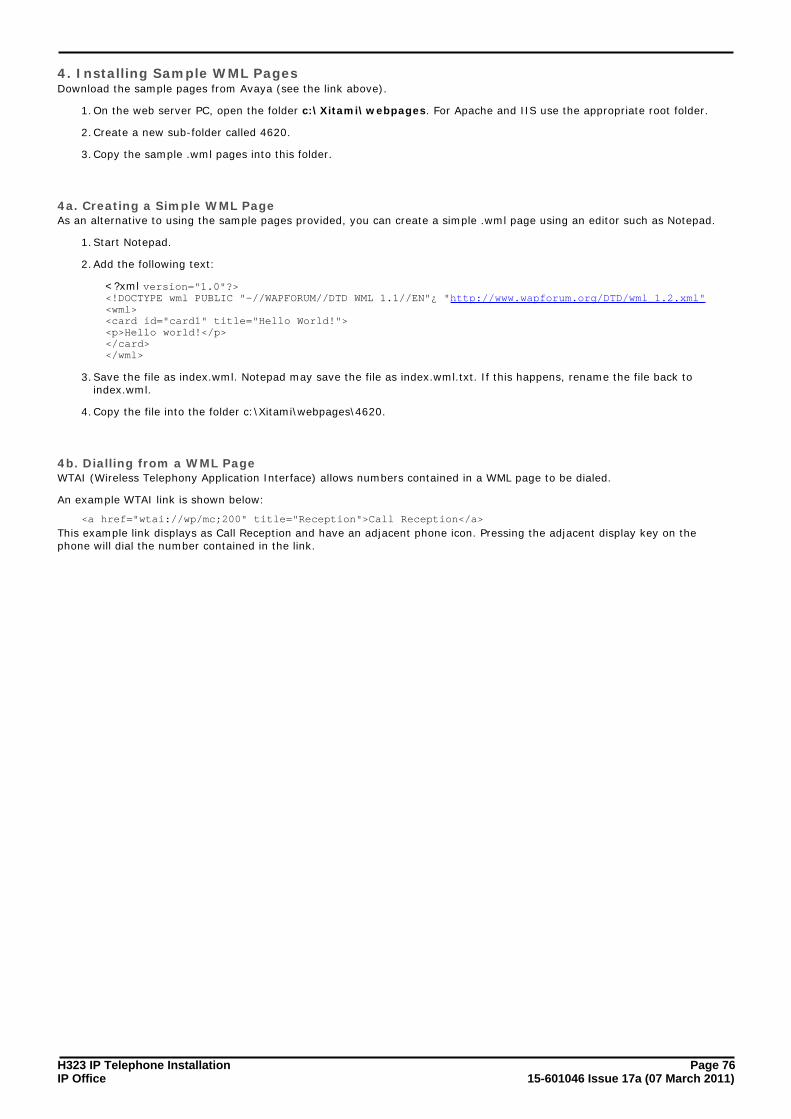
H323 IP Telephone Installation Page 7615-601046 Issue 17a (07 March 2011)IP Office
4. Installing Sample WML PagesDownload the sample pages from Avaya (see the link above).
1.On the web server PC, open the folder c:\Xitami\webpages. For Apache and IIS use the appropriate root folder.
2.Create a new sub-folder called 4620.
3.Copy the sample .wml pages into this folder.
4a. Creating a Simple WML PageAs an alternative to using the sample pages provided, you can create a simple .wml page using an editor such as Notepad.
1.Start Notepad.
2.Add the following text:
<?xml version="1.0"?><!DOCTYPE wml PUBLIC "-//WAPFORUM//DTD WML 1.1//EN"¿ "http://www.wapforum.org/DTD/wml_1.2.xml"<wml><card id="card1" title="Hello World!"><p>Hello world!</p></card></wml>
3.Save the file as index.wml. Notepad may save the file as index.wml.txt. If this happens, rename the file back toindex.wml.
4.Copy the file into the folder c:\Xitami\webpages\4620.
4b. Dialling from a WML PageWTAI (Wireless Telephony Application Interface) allows numbers contained in a WML page to be dialed.
An example WTAI link is shown below:
<a href="wtai://wp/mc;200" title="Reception">Call Reception</a>
This example link displays as Call Reception and have an adjacent phone icon. Pressing the adjacent display key on thephone will dial the number contained in the link.

H323 IP Telephone Installation Page 7715-601046 Issue 17a (07 March 2011)IP Office
WML Server Setup: Testing 4620 WML Browsing Using Xitami
8.2 Setting the Home PageWAP capable H323 IP phones display a key option labeled Web when setup with a home page (press PHONE/EXIT if inany other menu).
To access the home page, press the adjacent display key. The home page is set by editing the 46XXsetting.scr file foundin the IP Office Manager applications program folder.
· For testing and demonstration purposes Avaya host a set of WML files at http://support.avaya.com/elmodocs/avayaip/4620/home.wml.
· Most PC web browsers cannot display .wml files. However Opera is able display WML pages which makes it a usefultool with which to test WML access and operation.
1.Locate the 46XXsettings.txt file that has been previously downloaded to the phones. This will contain any customsettings for the Avaya IP phones being supported on the system.
· If only the file 46XXsettings.scr is present rename it as 46XXsettings.txt.
2.Double-click on 46XXsettings.txt. The file will open in Notepad. The section relating to WML browsing is towards theend of the file. It will look similar to the following:
################ SETTINGS FOR AVAYA 4620 IP PHONE ##################### 4620 Web Launch page in WML - Default: Avaya hostedSET WMLHOME http://192.168.42.200/4620/index.wml## The Proxy server used for your LAN - IP address or human readable name (check your browser settings).# SET WMLPROXY nj.proxy.avaya.com## The http proxy server port (check your browser settings).SET WMLPORT 8000## Exceptions: You must use an IP address not a DNS name# Example: SET WMLEXCEPT 111.222.333.444## Text coding for the web pages defaulted to ASCII.SET WMLCODING ASCII
##################### END OF AVAYA 4620 IP PHONE ####################
3.Edit SET WMLHOME to be the address of the sample index.wml file on the web server. In this example;http://192.168.42.200/4620/index.wml.
4.If DNS is being used to access the web server by IP name, the SET DOMAIN and SET DNSSRVR lines at the start ofthe 46XXsettings.scr file should be edited to match the LAN settings. The preceding #'s should be removed from thelines to make them active.
5.Close and save the file.
6.Restart the phones. Once the phone has restarted it should display Web as one of the screen option.

H323 IP Telephone Installation Page 7815-601046 Issue 17a (07 March 2011)IP Office
8.3 Apache Web Server WML ConfigurationApache is an open-source web server that is available on many platforms. Basic familiarity with Unix is necessary toconfigure it. The following is a step-by-step guide for configuring Apache Web-server:
1.To set MIME types in Apache, a plain text file called httpd.conf is used.
2.The location for this file varies depending on the individual setup, but the most usual path is /etc/httpd/conf/httpd.conf. If the operating system is Windows, then look for a folder called conf under where Apache is installed.
3.Using a text editor, open httpd.conf.
4.Scroll down to the AddType section (usually at the bottom of the file) and add the following line: AddType text/
vnd.wap.wml wml
5.Save the file.
8.4 Microsoft IIS Web Server WML ConfigurationMicrosoft Internet Information Server (IIS) is configured through the Internet Service Manager.
The following step-by-step guide can be used to set up MIME types necessary for WML:
1.Select Start | Control Panel | Administrative Tools | Internet Services Manager.
2.Right-click on Server and select Properties.
3.In the Computer MIME Map section, click Edit.
4.Click New Type and create a new file type using the parameters below:
· Associated extension: wml
· Content type: text/vnd.wap.wml
5.Click OK.
6.Stop and restart the web server so that the newly added MIME types are picked up.
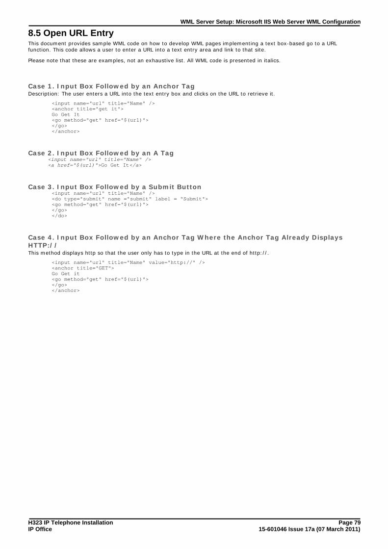
H323 IP Telephone Installation Page 7915-601046 Issue 17a (07 March 2011)IP Office
WML Server Setup: Microsoft IIS Web Server WML Configuration
8.5 Open URL EntryThis document provides sample WML code on how to develop WML pages implementing a text box-based go to a URLfunction. This code allows a user to enter a URL into a text entry area and link to that site.
Please note that these are examples, not an exhaustive list. All WML code is presented in italics.
Case 1. Input Box Followed by an Anchor TagDescription: The user enters a URL into the text entry box and clicks on the URL to retrieve it.
<input name="url" title="Name" /><anchor title="get it">Go Get It<go method="get" href="$(url)"></go></anchor>
Case 2. Input Box Followed by an A Tag<input name="url" title="Name" /><a href="$(url)">Go Get It</a>
Case 3. Input Box Followed by a Submit Button<input name="url" title="Name" /><do type="submit" name ="submit" label = "Submit"><go method="get" href="$(url)"></go></do>
Case 4. Input Box Followed by an Anchor Tag Where the Anchor Tag Already DisplaysHTTP://This method displays http so that the user only has to type in the URL at the end of http://.
<input name="url" title="Name" value="http://" /><anchor title="GET">Go Get it<go method="get" href="$(url)"></go></anchor>


H323 IP Telephone Installation Page 8115-601046 Issue 17a (07 March 2011)IP Office
Index
Index1100Mbps Ethernet 5410Mbps 1210MBps Ethernet 54
1151C1 19
1151C1/1151C2 321151C2 191152A1 32
150ms 14
1719,TFTPSRVR 69176 option 69192.168.202.x 45
192.168.202.X VLANTEST 45
192.168.42.200/4620/index.wml 77192.168.43.x 4519-inch 19
1b 29
1U 191W 19
225ms 15
264V AC 19
2a 692b 692c 69
2-second 65
33.5W 1930A Switch Upgrade Base 193600 7
3616 7
3b 333-party
configuring 11
44.0W 19
4.1W 194.6W 194.9W 19
45-days 42
4600 7, 29, 40, 42, 45, 68, 74created 69
4600 Series IP Telephone LAN Administrator's Guide 42
refer 74
see 684600 Site Specific Settings 294601dape1_82.bin 21
4601dbte1_82.bin 21
4602dape1_82.bin 214602dbte1_82.bin 214602sape1_82.bin 21
4602sbte1_82.bin 21
4602SW 7, 18, 194606 7, 18, 19
includes 64
4610SW 7, 18, 19, 42, 74
4620 7, 19, 29, 64, 74, 75relating 77
4620IP 18
4620SW 7, 18, 42, 74
4621SW 7, 42applies 19
4622
support 7
4624D 194624D01 194624D02A 54
4625SW 19, 42
46setting files 4546vpnsettings.txt file 4246xx
VPNremote 42
46xxOptions 6946XXsetting.scr 7746XXsetting.scr file
editing 77
46xxsetting.txt file 5846xxsettings file 4546XXsettings.scr 29
back 77
edit 5246XXsettings.scr file
46XXsettings.txt 77
start 77
46XXsettings.txt 26, 2946XXsettings.scr file 77
46xxsettings.txt file
Creating 29
46XXupgrade.scr 6046xxupgrade.scr file
lines 29
46xxupgrade.scr file instruct
phone 2947
63HZ 19
4a 75
4b 75
55.0W 195.9W 19
5601ape1810.bin 21
5601bte1810.bin 215602dape1806.bin 215602dbte1806.bin 21
5602sape1806.bin 21
5602sbte1806.bin 215602SW 7, 18, 195610SW 7, 18, 42, 74
5620SW 7, 18
5621SW phones 42
66.0W 196.45W 19
63HZ
47 1964ms 156k3 15
77.7W 19
792ms PRN 39
88.0W 19801.11b 7
802.11a/b/g 7
802.11b 7802.1p 45802.1Q 33, 45, 53
802.3af 19

H323 IP Telephone Installation Page 8215-601046 Issue 17a (07 March 2011)IP Office
8k 15
99.9W 1990
PSU requires 19
Aa10d01b2_2.bin 21
a20d01a2_2.bin 21a20d01b2_2.bin 21AC 19
access point 7
Access Points 7Action 31, 35Activate
Scope 69
Active Directory using RADIUS 42Add 19, 31, 42, 45, 75, 78
clicking 69
ADDR 40
address 12, 17, 21, 33, 35, 40, 45, 56, 57, 60, 64, 65, 68,69, 72, 75, 77
PC 26address programming 33
Address View 65
AddType 78AddType text/vnd.wap.wml wml 78Administrative 54, 69, 78
Administrative Details 54
administrative options 52, 54Administrative Tools 69, 78Adtran Netvanta 3305 VPN Router 42
Advanced 77
AGC 58ains600,2600,192.168.42.10,1026 39All LAN 12
All Tasks 69
Alternate 11, 26, 68, 72Alternate DHCP Servers 11, 26
Avaya IP 68
Alternate Options 72
Anchor Tag 79Anchor Tag Already Displays HTTP
Anchor Tag Where 79
Anchor Tag Where
Anchor Tag Already Displays HTTP 79Apache 78Apache Web Server 78
Apache Web-server 78
Apache-Tomcat 42Appearance 31, 35Appendix 60
appendix explains 60
application file 40, 54, 60, 61Application File Already Loaded 61Application File Needs Upgrading 61
Application Notes
Configuring 42Applications 14, 21, 40, 42, 54, 56, 60, 61, 69, 75, 77applies 17, 34, 40, 60
4621SW 19
ASCII defaulted 77
ASDM 42
attaching
Option 66 69
Audio 53
Auto-create Extn Enable 26, 35Automatic Gain Control 58Automatic Selection 35
auto-negotiated 15
autorun 21autorun during PC 21Avaya 18, 19, 23, 42, 45, 68, 77
escalated 14
including 21number 7
Avaya 1151C1 19
Avaya 1151C2 19
Avaya 1152A1 Power Distribution Unit 19Avaya 30A Switch Upgrade Base
fitting 18
Avaya 4622SW IP Telephone 42
Avaya Gateways 42Avaya H.323 IP 7Avaya IP 42, 45
Alternate DHCP Servers 68
Avaya IP Office 42, 45Avaya P333T-PWR Switch 19Avaya SG Series 42
Avaya Voice Priority Processor 7
Avaya VSU Series 42Avaya WebLM 42Avaya WebLM Software 42
AvayaLabs 45
Avays VSU Series 42Avoid Hubs 17AVPP 7
Bb10d01b2_2.bin 21
b20d01a2_2.bin 21b20d01b2_2.bin 21back 33, 69
46XXsettings.scr 77
index.wml 75IP 18, 32Manager PC's 23
back spacing 33
backlight 19Backup 17, 19bbla0_83.bin 21
Beam Address 65
Beam Contact 65Beaming
Files During 66
beaming files 66
bin/VPN Phone 42Blue 45boot 7, 33, 52, 54, 56, 60, 61
Boot File 7, 33, 52, 54, 60, 61
Boot File Needs Upgrading 61Browsing Using Xitami 75Button Programming 31
Cc0a82c15 39
cabling 12Connections 17
Call 7, 12, 15, 17, 29, 34, 35, 40, 42, 45, 75, 78
During 66
subnet 33Swap Text Files During 64

H323 IP Telephone Installation Page 8315-601046 Issue 17a (07 March 2011)IP Office
Index
call answering 7
Call Reception 75Call Server 45call signalling 15
called 46xxsettings.txt 29
called CCD 42Callserver 69CallSv 33
CallSvPort 33
card1 75cat 5 12CAT3 19
Existing 12
CAT5 12, 17, 19CAT5 cabling 12Catalyst
changes 19
provide 19Category 12, 40cause 17
timeout 40
CD 21, 42, 75CD/DVD 42changes 12, 21, 23, 26, 29, 31, 33, 34, 35, 45, 52, 53, 57,61, 65
Catalyst 19
checkbox 42Cisco
Configuring 42
Cisco Adaptive Security Device Manager 42
Cisco Catalyst 19Cisco PIX 500 Series Security Appliances 42Cisco PIX Security Appliance
Configuring 42
Cisco VPN 300 Series Concentrators 42Cisco VPN 3000 Series Concentrators 42Clearing 61
CLI configuration 45
clicking Add 69
Close 14, 39, 75, 77, 78
cmd
Windows 39codecs 15Compact Flash 23
Compaq iPAQ Pocket PC 65
Compression Mode 35Computer Management 69Computer Management Tree 69
Computer MIME Map 78
Concentrator 42conf 78configuration 7, 12, 14, 18, 21, 26, 31, 35, 40, 42, 45, 57,68, 74, 77, 78
file source 23
Microsoft IIS 78configuration back 23, 31, 35, 42, 57Configuration Quick Start 42
configuring
3-party 11Application Notes 42Cisco 42
Cisco PIX Security Appliance 42
File Source 23VPN Remote 42
CONFLICT 40
Connect 12, 15, 17, 18, 42, 45
LAN 32Connections 12, 18, 19, 32, 40, 42, 53, 54, 65
Cabling 17
Contacts 64, 65
Control Panel 78Control Unit Memory Card
Using 23
Control Unit Settings 26
Correct Boot File 61Creating 45
4600 69
46xxsettings.txt File 29
Scope 69Simple 75
Currently VPNremote Phone 42
DData 14, 15, 17, 18, 19, 32, 33, 45, 56, 69
Data occupy 45data VLAN’s 45Data/Common/WML/samples 75
def06r1_8_3.bin 21
def24r1_8_3.bin 21Default 15, 33, 35, 42, 53, 56, 57, 61, 65, 69, 75
ASCII 77
defaults 56
defines 45, 57, 68IP 69
Definity 68
Deployment Guide 42
DHCP 11, 12, 14, 21, 33, 40, 45, 52, 56, 57, 60, 72alternate 68connection 32
introduction 7
preparation 26windows 69
DHCP Address Installation 32, 33
DHCP addressing 57
DHCP Options 45, 57, 69DHCP Relay 45DHCP Server 11, 12, 21, 26, 32, 33, 40, 45, 57, 68, 69, 72
DHCP server assigning 40
DHCP Settings 45DHCP Setup
H.323 IP Phones 69
dialling 64, 65, 75
dialling contacts 65Dialling Phone Numbers 65DiffServ 17
IP Office supports 17
DiffServ QoS 17Digital Telephony 35Direct Media 15
Disable Auto-Create Extension 35
display 26, 31, 32, 33, 34, 35, 53, 54, 55, 56, 57, 58, 60,61, 65, 66, 75, 77, 79
IR 65displayed Beam option 66
displays Clearing 61
displays Initializing 32, 61displays Loading 61DNS 68, 69, 72, 77
DNS Domain Name 68, 72
DNS Server Address 68, 72Doc Reference 42DOCTYPE wml PUBLIC 75

H323 IP Telephone Installation Page 8415-601046 Issue 17a (07 March 2011)IP Office
Documentation CD 75
Double-click System 57Duplicate IP Addressing 17during
Call 66
Manager 12DVD 42
EEdit SET WMLHOME 77
editing 78
46XXsetting.scr file 7746XXsettings.scr 52
Embedded Voicemail Memory 21
END OF AVAYA 4620 IP PHONE 77
END OF FILE 29Endpoints 39End-to-End Matching Standards 17
English 40
Enter 12, 21, 23, 26, 31, 32, 33, 34, 35, 39, 42, 53, 57, 65,72, 75, 77, 79
subnet 69WINS 69
Enter cmd 23, 39
Enter tftp 39entered during 53error messages 40
escalated
Avaya 14etc/httpd/conf/httpd.conf 78Ethernet 17, 40, 45, 60, 65
Power 19
Ethernet LAN 19Ethernet Switch 45EU24 19
EU24BL 19
Example setup - Overview 45Excessive Utilization 17Existing
CAT3 12
Ext 34extension 35Extension ID 31
Extension Number 12, 26, 31, 34, 35, 61
IP phone 40extensions 7, 12, 15, 26, 31, 34, 35, 40, 42, 64, 66, 77, 78
phone requests 61
user changes 61
Extn 31, 35Extn2601,2601,192.168.42.4,1720 39Extn2602,2602,192.168.42.2,1720 39
Ffile 21, 23, 26, 29, 34, 39, 40, 42, 45, 54, 56, 60, 61, 64,65, 66, 69, 75, 77, 78
phone displays 61File Source
Configuring 23
File Writer
set 23filename1 54filename2 54
Files During
Beaming 66FileSv 33Find 55
Finish 69, 75
fitting
Avaya 30A Switch Upgrade Base 18
following H.323 IP 7
form 23, 26, 39
Quality 17
Full Name 35
GG.711 15G.723 15
G.729a 15
G.729b 15gatekeeper 11, 12, 26, 33, 35, 57, 69, 72Gatekeeper Enabled 26
Gatekeeper Settings 26
GEN phone 19
GEN1 19
GEN1 4612 19
GET 79Get It 79Get It</a 79
gif 75
GRQ 39gvrp 45
HH.08.60 45
H.232 18
H.323 7, 11, 12, 14, 15, 18, 19, 21, 26, 29, 39, 40, 52, 53,57, 58, 64, 65, 68, 69, 72, 75, 77H.323 Gatekeeper 11H.323 IP 12, 15, 18, 21, 26, 29, 39, 40, 52, 53, 57, 58, 64,65, 68, 72, 75, 77
following 7
including 19installing 14, 69number 7
provide 11
H.323 IP phone requires 19H.323 IP phones 7, 11, 12, 15, 18, 19, 21, 26, 29, 39, 53,58, 65, 68, 72, 75, 77
DHCP Setup 69
H323 Gatekeeper 12, 69
Hello World 75Hold 33, 53, 54, 55, 56, 58, 65home page 29, 74, 77
hostname 45
HP 45HP Procurve 45HP Procurve CLI 45
HP Procurve Ethernet 2626 PWR Ethernet 45
HP Procurve Switch 45HP-Switch 45href 75, 79
htm 75
HTML 74, 75httpd.conf 78
Ii10c01a2_2.bin 21
i10d01a2_2.bin 21
i20d01a2_2.bin 21IEEE 802.2p/q
understanding 45
IEEE 802.3af 18, 19
IIS 78IIS 5.0 78

H323 IP Telephone Installation Page 8515-601046 Issue 17a (07 March 2011)IP Office
Index
IIS Admin Service’ 78
IKE Extended Authentication 42Immediate 31, 35, 69Important Note 64
Inactive 69
includes 11, 14, 26, 39, 45, 65, 754606 64Avaya 21
H.323 IP 19
PC 18WAN Ethernet 17
index.wml 77
back 75
index.wml file 77index.wml.txt 75Infrared Dialling 64
Initializing 32, 61
Input Box Followed 79installation 17, 21, 26, 29, 32, 35, 42, 52, 56, 68, 74, 75,77
DHCP 7
requirements 12
small 11static address 33
Installation Documentation 42
Installation Requirements 12
installing H.323 IP 14, 69IP 12
Sample 75
VCM 15Web Server 75
Internet 42, 78
Internet Authentication Service 42
Internet Service Manager 78Introduction 7, 75IP 11, 14, 15, 17, 21, 23, 26, 29, 31, 34, 35, 39, 40, 42, 45,52, 56, 57, 60, 61, 64, 68, 72, 74, 75, 77
back 18, 32
defines 69install 12match 33
power 19
Select 65start 55use 7
IP address 12, 17, 21, 23, 26, 31, 32, 33, 35, 39, 40, 45,60, 68, 69, 72, 75, 77
ip address 192.168.202.201 255.255.255.0 45IP Address and/or MAC Address 31IP Address LAN2 45
IP Gateway 68
IP Mask 33, 45IP Mask LAN1 45IP Mask LAN2 45
IP Office 7, 11, 12, 14, 15, 17, 19, 21, 23, 26, 29, 31, 33,34, 35, 39, 40, 42, 45, 56, 57, 61, 65, 68, 69, 75, 77
IP Office Administration CD 26IP Office Administrator 21, 42IP Office Administrator Applications CD 21
IP Office Documentation CD 75
IP Office Embedded Voicemail 21IP Office Engineers 75IP Office Engineers Toolkit 75
IP Office IP Endpoint 7
IP Office LAN 75
IP Office Licensing 42
IP Office Manager 7, 11, 12, 21, 29, 31, 34, 35, 40, 42, 57,61, 77IP Office Manager application 7, 11, 12, 21IP Office Manager PC 12
IP Office Manager System 35
IP Office Monitor application 26, 39IP Office supports 7
DiffServ 17
IP Office System 7, 11, 14, 15, 23, 39, 42, 56, 65
IP Office Unit 7, 11, 12, 15, 17, 21, 23, 26, 33, 39, 40, 68,69IP Office Unit configuration 12IP Office Unit Memory Card 21
IP Office Unit's LAN1 69
IP Office's configuration 42IP Office's data 15IP Office's LAN1 21, 26
IP Office's TDM 15
IP phone 7, 11, 12, 18, 19, 21, 26, 31, 32, 35, 42, 45, 52,55, 57, 64, 65, 68, 69, 72, 75, 77
extension number 40IP Phone Inline Adaptor 19
IP Phone Software 7, 21, 26
IP Phone Software Version 7IP Softphone Fails To Register With 42IP Telephone 12, 42, 68, 74
IP Telephone LAN Administrator's Guide 68, 74
IP Telephone R2.3 LAN Administrator Guide 42IP Telephone Software 12IP Telephones Administrators Guide 42
IP400 42
IP403 7, 15IP406 7, 15, 21, 23, 26IP406 V1 7, 15
IP406 V2 7, 15, 21, 23, 26
IP412 7, 15IPO 42, 45IPO LIC 42
IPSec VPN 42
IPSets Firmware 21IPSets Firmware/4601dbtel1_82.bin 23IR 53, 64, 65, 66
display 65
PC/Handheld 65IR beaming 64IR Interface Enable/Disable 53
IR port 53, 64, 65, 66
IR port ready 66IrDA 64ISG 42
JJ8164A Configuration Editor 45
Java 42jpg 75JRE 42
Juniper Networks Integrated Security Gateway 42
Juniper Networks NetScreen 42Juniper Networks NetScreen Series VPN 42Juniper Networks Secure Services Gateway 500 Series 42
Juniper Secure Services Gateway using Policy-Based 42
KKentrox Q2300 VPN Router 42
LL2 45, 53

H323 IP Telephone Installation Page 8615-601046 Issue 17a (07 March 2011)IP Office
L2 QOS 45
L2 signaling 53L2Q 45L2QVLAN 45
L3 53
L3 signaling 53LAN 17, 18, 19, 40, 42, 45, 53, 54, 60, 68, 74, 75
Connect 32
match 77
PC 12LAN Administrator's Guide 68, 74LAN Cables 12, 18, 19, 32, 77
LAN PC's 75
LAN Socket 12, 53LAN1 23, 26, 33, 45, 69LAN2 45
LAN's DHCP 60
Leave Manager 26LED 19
waiting 55
Licence Keys 12
license key 12LINE 19, 32lines 39, 42, 60, 61, 75, 77, 78
46xxupgrade.scr file 29
Monitor 26Listing
Registered 39
Loading 60, 61
Loading… 32login 35Login Code 34, 35
MM505 65, 66
MAC 35, 42, 54MAC Address 35, 42, 54Maintenance Manual 7
manage
VLAN’s 45Manager 11, 21, 23, 26, 29, 31, 33, 35, 42, 68, 69, 77, 78
during 12
Manager application 11, 21, 26, 29, 33
Open 77Manager Installation 7, 12Manager PC 23, 26, 77
Manager PC's
back 23Manager's TFTP Log 26Mandatory 14, 53
Manually Creating Extensions 31
match 17, 31, 35, 57, 61IP 33LAN 77
RJ45 19
May 2007 7Mbps 60MCIPADD 45, 69
MCPORT 45, 69
Menu icon 65, 66MESSAGES button 34MESSAGES button flashing 0.5 34
MG 7
Microsoft 42, 72, 78Refer 69
Microsoft DHCP 72
Microsoft IIS Web Server 78
Microsoft Internet Information Server 78
Microsoft Windows 2000/server 78Microsoft Windows NT 78Microsoft Windows XP 78
Mid-Span Power Unit 19
MIME 78set 75
Minimum Assessment Target 14
Minimum Firmware 42
MMC 78Mode option 45Mode option MUST 45
Monitor 14
lines 26multicast 17Multicasting 17
Multihomed 45
MultiVantage 68
NName 12, 18, 21, 26, 31, 35, 39, 42, 45, 54, 61, 65, 69, 72,75, 77, 79Name Details 26
nasystem/h323_ras_list yyyyyyyy.txt 39
Native 45Netgear FVS338 VPN Router 42Network Access 17
network assessment 7, 14
New 17, 26, 31, 33, 34, 35, 45, 52, 53, 57, 60, 61, 69, 75,78New Type 78New,2702,192.168.42.200,1720 39
Next 61, 69
NIC Cards 45No Ethernet 32, 40, 60No new 53
Non-Avaya 23, 42
Non-Avaya Gateways 42non-IP 15, 34
number 7
non-IP extension 34
non-VoIP extension 31Notepad 75, 77, 78NT 4.0 78
Number 12, 15, 18, 19, 26, 31, 33, 34, 35, 42, 52, 54, 57,60, 61, 65, 66, 69, 74, 75
Avaya 7H.323 IP 7non-IP 7
Start 64
VCM 7
OOK 23, 31, 35, 42, 57, 69, 78on/off 34, 58
onthe phone button 65
Open 17, 26, 35, 39, 78, 79Manager application 77PC's 75
Open URL Entry 79
operate 78Option 12, 19, 21, 29, 39, 40, 42, 45, 52, 53, 54, 57, 66,69, 72, 77, 78Option 15 72
Option 176 72
requesting 69Option 66 72
attaching 69

H323 IP Telephone Installation Page 8715-601046 Issue 17a (07 March 2011)IP Office
Index
Option Settings 53
options exist 12OR 77Other H.323 IP 7
Overlapping VLAN 45
Pp>Hello world!</p 75Packet Loss 14page coding 74
Pages 74, 75, 77, 78, 79
pages implementing 79Palm 65, 66Palm Organizer 65, 66
Palm Vx 65, 66
part 21, 29, 42, 69Scope 72
Password 34, 61, 75, 77
PC 7, 21, 23, 33, 42, 45, 53, 60, 64, 65, 68, 75, 77
address 26include 18LAN 12
running 69
PC Ethernet LAN 18PC Port 18PC Softphone 7
PC/Handheld
Ir 65PC/personal 64PC’s 45
PC1 45
PCs 45PC's 18
Open 75
PC's web 75
phone 7, 11, 12, 14, 15, 17, 18, 21, 26, 31, 33, 35, 40, 42,45, 52, 53, 54, 55, 56, 57, 58, 60, 61, 65, 66, 68, 69, 72,74, 75, 77
46xxupgrade.scr file instruct 29connection 32
dialling 65
GEN 19infrared dialling 64registration 34, 39
security 35
Phone Connection 32phone displays 34, 61, 77
file 61
phone during installation 12, 26, 68
Phone Manager 7Phone Manager Pro PC Softphone 7phone obtains 60
phone requests 29, 42, 77
extension 61phone requires 12phone returns 53, 55
Phone Security 31, 35
Phone SN 54PHONE/EXIT 77phone's Differential 53
phone's Differential Services 53
phone's IP Mask 33phones look 11phones need 69, 74
Phones share 45
PHY2 53, 65Pocket PC 65
PoE 19
PoE input 19Potential Problems 17Potential VoIP Problems 17
power 12, 17, 18, 32, 34, 40, 60
Ethernet 19IP 19
power conditioning 17
power over ethernet 18, 19
Power over Ethernet Options 19power supply 12, 17, 19, 32Power Supply Conditioning 17
Power Supply Options 19
Power Supply Unit 12, 19, 32Predefined 69Pre-Deployment 42
Preferences 26
Prefs 65preinstalled 26preparation 26, 61
Preshared Key 42
Press Web 77Print 35, 39, 54Printed Wiring Board 54
Printed Wiring Board Serial Number 54
prioritisation 45prioritization 17Product Section 42
Program 12, 21, 33, 69, 75, 77
Program Files/Avaya/IP Office/Manager 77Program Files/Avaya/IPOffice/Toolkit/Data/Common/WML/samples 75Properties 75, 78
Protection 17
Protocol timeout 40provide switching 18provides 12, 14, 15, 17, 18, 21, 29, 42, 45, 75, 79
Catalyst 19
H.323 IP 11RJ45 19
Proxy 77
PSK 42
PSU 19PSU requires
90 19
PWB comcode
Shows 54PWB SN 54
QQoS 17, 53
QoS Option Settings 53
Quality 7, 14, 17form 17Service 53
RRAM 60, 61
RAS 39, 69RAS users 39Reboot 23, 31, 35, 57, 61, 69, 77
Restarting following 40
Reboot Mode 57Set 31, 35
Reception">Call Reception</a 75
Red 32, 45
refer 7, 19, 42, 45, 64, 75

H323 IP Telephone Installation Page 8815-601046 Issue 17a (07 March 2011)IP Office
refer 7, 19, 42, 45, 64, 75
4600 Series IP Telephone LAN Administrator's Guide 74Microsoft 69
Registered 42, 69
Listing 39
registration 34, 61, 69relating
4620 77
Release 2.0 Administrator Guide 42
Release 4.3 Administration Guide 42repost 45requesting
Option 176 69
Reset System Values 56reset sytem values 56Resetting 56
restart 11, 21, 34, 40, 45, 56, 60, 61, 65, 77, 78
Restart Scenarios 60Restarting following
reboot 40
Restarting… 60
RFA Name 42RFC2474 17RJ45 12
matching 19
provides 19RJ45 Ethernet LAN 12RJ45 LAN 12
Run 7, 11, 12, 17, 19, 21, 23, 26, 33, 39, 40, 42, 68, 75,77, 78
PC 69
SSample 77, 79
Installing 75
SAP Code 42
Save 33, 40, 42, 53, 57, 61, 75, 77, 78savilltech.com 69Scope 45, 68
Activate 69
Creating 69part 72
Scope Options 45, 69
scr 77
scr extension 77Screen OS 5.1.0 42script file 40, 52, 60, 61
Secondary Ethernet 53
see 11, 12, 14, 26, 29, 31, 32, 33, 34, 39, 52, 53, 56, 58,69, 75, 77
4600 Series IP Telephone LAN Administrator's Guide 68
select 23, 31, 34, 35, 39, 42, 45, 57, 66, 69, 75, 77, 78
IP 65
System 26Select Add 69select All Tasks 69
Select File 26, 77
Select Immediate 57Select No 69Select Start 23, 39, 69, 78
Select View 26, 77
Select Yes 69Self Installer 42self test 55
Self-Test Procedure 55
sendable 66
Serial Number 54Series 7, 19, 29, 40, 42, 45, 68, 74Series H.323 IP phones 40
Series IP Phone 29
Series phone 40Server 11, 21, 23, 40, 42, 45, 60, 68, 69, 72, 75, 77, 78Service 17, 21, 42, 69, 78
Quality 53
Type 17Services signaling 53Set 14, 21, 26, 29, 33, 34, 35, 40, 45, 52, 53, 54, 58, 64,65, 66, 69, 72, 74, 77, 78
File Writer 23
MIME 75Reboot Mode 31, 35SSON 57
SET DNSSRVR 77
SET DOMAIN 77SET L2Q 29SET SMBLIC 42
SET WMLCODING ASCII 77
SET WMLEXCEPT 111.222.333.444 77SET WMLHOME 77SET WMLPORT 8000 77
SET WMLPROXY nj.proxy.avaya.com 77
SETTINGS FOR AVAYA 4620 IP PHONE 77Setup 31, 35, 45, 56, 60, 65, 77, 78Several H.323 IP phones 64
SG 42
Shows 11, 17, 39, 45, 55, 65PWB's comcode 54
Simple 45, 74
Creating 75
site specific option number 57Site Specific Settings 29Small Installation 11
Small Office Edition 7, 12, 15, 17, 21, 23, 26
snmp-server 45Spare Wire 19Spare Wire Power Options 19
Speaker/Mute LED 55
Specifically HP 45SSON
Setting 57
Start 17, 23, 26, 33, 39, 42, 45, 60, 61, 69, 75, 78
46XXsettings.scr file 77IP 55Number 64
start installing 69
Start Manager 77Start Notepad 75static address 7, 21, 26, 32, 40, 52, 54, 60
installation 33
Static Administration Options 52Static IP 7, 12, 26Static IP Installation 7
Step 32, 33, 60, 68
stores 23, 34, 40, 61String
Verify 69
Submit Button 79
subnet 45, 68called 33Enter 69
subnet mask 33, 68, 69

H323 IP Telephone Installation Page 8915-601046 Issue 17a (07 March 2011)IP Office
Index
support.avaya.com 42
Supported 11, 12, 14, 15, 17, 19, 21, 23, 32, 33, 42, 45,64, 66, 68, 72, 74, 75
4622 7SV 7
SW 18
Swap Text Files During Call 64
Sysmon 39
System 7, 12, 17, 19, 21, 23, 31, 35, 39, 40, 45, 52, 56,57, 66, 68, 74, 77, 78
select 26System | System 21System Name 26
System Overview 45
system-specific 61System-specific registration 61
TTag 45, 74, 79
Tagged Packets 45
Technical Tip No 42text/vnd.wap.wml 75, 78TFTP 11, 14, 33, 39, 40, 42, 45, 56, 60, 61, 68, 69, 72, 77
control unit memory card 23
installation 12introduction 21preparation 26
timeout waiting 21
TFTP Error 40, 60TFTP Introduction 21TFTP Log 21, 26, 77
TFTP Server 11, 12, 21, 23, 26, 33, 40, 42, 56, 60, 61, 68,69, 72, 77
TFTP Server Name 72TFTP Server Options 12TFTPDIR 69
TFTPLog 26
TFTPSRVR 45, 69These 7, 15, 19, 21, 32, 35, 39, 45, 52, 54, 64, 79These require
VPNremote 7
Third-TFTP Software 21Timed Out 40, 60timeout 21
cause 40
Timeout Error 40timeout waiting
TFTP 21
Tomcat 42
toolkit 75Tools 21, 29, 39, 65, 69, 78ToS 17
Trial 42
txt file 29Type 7, 11, 14, 15, 19, 23, 39, 45, 66, 69, 75, 78, 79
Service 17
UUnder Services 69
understanding IEEE 802.2p/q 45
unit’s 45
Unix 78
Unrestricted 45Untagged 45upgrading
application file 61
boot file 61
URL user enters 79
URQ 40
US 54
use 11, 12, 17, 19, 23, 31, 34, 35, 39, 40, 42, 45, 52, 53,54, 56, 60, 61, 64, 65, 68, 69, 75, 77
IP 7VCM 15
user 12, 17, 18, 26, 31, 34, 35, 39, 42, 45, 54, 58, 61, 75,78, 79
user changes extension 61
User Details 12
user enters
URL 79User Name Details 26User PC Connection 18
User Setup 35
user's Login Code 34, 35, 61Using 7, 15, 17, 19, 21, 26, 29, 34, 35, 39, 40, 42, 45, 52,57, 60, 61, 64, 65, 66, 68, 69, 72, 75, 78
Control Unit Memory Card 23
Using Manager 23
Using Option 66 72Using Windows 2000 Server 69
VVCard 65, 66
VCard file 65
VCard phone 65vcf 65VCM 26
installing 15
number 7use 15
VCM 10 15
VCM 16 15
VCM 20 15VCM 24 15VCM 30 15
VCM Channels 7, 15
VCOMP 26Verify 40
String 69
View 21, 26, 54, 74
View Administrative Details 54VLAN 33, 45, 69vlan 209 45
vlan 210 45
VLAN ID 33, 45VLAN networking 45VLAN Switch Configuration 45
VLAN’s
manage 45VLANID 45VLANTEST 45, 69
Voice 7, 12, 14, 15, 17, 18, 26, 45
voice compression 17, 26channels 15installation 12
Voice Compression Channel Capacity 15
Voice Compression Channels 15, 26Voice Compression Module 12, 26voice signalling 17
voice traffic 14, 18, 45
voicemail 17, 23, 31
H323 IP Telephone Installation Page 9015-601046 Issue 17a (07 March 2011)IP Office
Voicemail Server PC 17
VoIP 7, 12, 14, 17, 31, 34, 35, 42VPN 42VPN Devices 42
VPN Phone Allowed 42
VPN Phone Allowed checkbox option 42VPN Phone Unlimited 42VPN phones 42
VPN Remote
Configuring 42VPN Remote Phones 42VPN Security Gateway 42
VPN Security Gateway Device 42
VPN Wizard 42VPNremote
46xx 42
These require 7
VPNremote Phone 42VPNremote Phone Firmware 42VPNremote Phone License File 42
VPNremote Phone Licenses 42
VSU 42
Wwaiting
LED 55
WAN 17
WAN Ethernet including 17
WAP 74, 77
Web Server 75
WAP browsing 74WAP browsing uses 75WAP MIME 75
WAPFORUM//DTD WML 1.1//EN"¿ 75
WARNING 14, 33, 56, 57Watts 19wbmp 75
Web 29, 42, 45, 75, 77, 78
web browsing 29, 75Web Launch 77Web Server 77, 78
Installing 75
WAP 75web server needs 75Web Server PC 75
WebLM 42
WebLM server 42website 42When Free 31, 35, 57
Windows 23, 29, 64, 68, 72, 75, 77, 78
2000 69cmd 39pocket PC 65
Windows 2000/server 78
Windows Notepad 29Windows NT 78Windows PC 75
Windows Pocket PC 65
Windows XP 78winnt/system32/inetsrv/iis 78WINS 68
Enter 69
Wireless Access Protocol 74Wireless Markup Language 74Wireless Telephony Application Interface 74, 75
Within Manager 26
WML 29, 74, 75, 77, 78, 79
WML browsing 77WML Page 75wml pages 75
WML Server Setup 74
Wordpad 39, 75Worst Case 19wp/mc;200 75
Wrong Set Type 34, 40
WTAI 74, 75www.wapforum.org/DTD/wml_1.2.xml 75
Xx10d01a2_2.bin 21
x20d01a2_2.bin 21
Xauth 42XAuth Enhanced Authentication 42Xitami 75
Xitami.cfg 75
Xitami.exe 75Xitami/webpages 75Xitami/webpages/4620 75
xml 75
xx.xxx.xxx.xxx 69xxx.xxx.xxx.xxx 39xxx.xxx.xxx.xxx,MCPORT 69
Yyyy.yyy.yyy.yyy 69
yyy.yyy.yyy.yyy,TFTPDIR 69yyyyyyy.txt 39

H323 IP Telephone Installation Page 9115-601046 Issue 17a (07 March 2011)IP Office

H323 IP Telephone Installation Page 9215-601046 Issue 17a (07 March 2011)IP Office
Performance figures and data quoted in this document are typical, and must bespecifically confirmed in writing by Avaya before they become applicable to anyparticular order or contract. The company reserves the right to make alterationsor amendments to the detailed specifications at its discretion. The publication of
information in this document does not imply freedom from patent or otherprotective rights of Avaya or others.
All trademarks identified by the ® or ™ are registered trademarks or trademarks,respectively, of Avaya Inc. All other trademarks are the property of their
respective owners.
This document contains proprietary information of Avaya and is not to bedisclosed or used except in accordance with applicable agreements.
© 2011 Avaya Inc. All rights reserved.


