59
1 IP PBX STATIONS Istanbul Arel University Bachelor's Degree Thesis Ahmet Emre BAKKAL 2013

1
IP PBX STATIONS
Istanbul Arel University
Bachelor's Degree Thesis
Ahmet Emre BAKKAL
2013
2
IP PBX STATIONS
Dissertation written by
Ahmet Emre BAKKAL
Approved by
___________________________________ , Chair, Dissertation Committee
___________________________________ , Members, Dissertation Committee
___________________________________
___________________________________
___________________________________

3
ACKNOWLEDGEMENTS
I would like to express my deepest appreciation to all those who provided me the possibility to complete this thesis. A special gratitude I give to our graduated project manager, Assoc.Prof.Dr.Hasan Hüseyin BALIK, whose contribution in stimulating suggestions and encouragement, helped me to coordinate my project especially in writing this report. Furthermore I would also like to acknowledge with much appreciation the crucial role of my teacher Assoc.Prof.Dr.Hasan Hüseyin BALIK who gave the permission to use all required equipment and the necessary materials to complete the task “IP PBX PHONE SYSTEM ”. A special thanks goes to my team mate, Seda TEMEL, who help me to assemble the parts and gave suggestion about the task “IP PBX PHONE SYSTEM”. I have to appreciate the guidance given by other supervisor as well as the panels especially in our project presentation that has improved our presentation skills thanks to their comment and advices
Ahmet Emre BAKKAL
Defense Date: 04.07.2013 Istanbul
Istanbul Arel University
TABLE OF CONTENTS

4
ACKNOWLEDGEMENTS .................................................................................................................... 3
LIST OF FIGURES ...................................................................................................................................... 6
LIST OF TABLES ........................................................................................................................................ 7
1 INTRODUCTION ................................................................................................................................ 8
2 DATA COMMUNICATIONS ........................................................................................................... 11
2.1 Convergence of Computing and Communications ...................................................................... 12
2.1.1 What is Data Communications? ........................................................................................... 12
2.1.2 Communications Channels ................................................................................................... 13
2.1.3 Serial Communications ........................................................................................................ 14
2.1.4 Asynchronous vs. Synchronous Transmission ..................................................................... 15
2.1.5 The ASCII Character Set ..................................................................................................... 17
2.1.6 Parity and Checksums .......................................................................................................... 18
2.1.7 Data Compression ................................................................................................................ 19
2.1.8 Data Encryption .................................................................................................................... 19
2.1.9 Data Storage Technology ..................................................................................................... 20
2.1.10 Data Transfer in Digital Circuits ........................................................................................ 20
2.1.11 Transmission over Short Distances (< 2 feet) .................................................................... 21
2.1.12 Noise and Electrical Distortion .......................................................................................... 21
2.1.13 Transmission over Medium Distances (< 20 feet).............................................................. 23
2.1.14 Transmission over Long Distances (< 4000 feet) ............................................................... 24
2.1.15 Transmission over Very Long Distances (greater than 4000 feet) ..................................... 25
2.2 Computer Networks .................................................................................................................... 26
2.2.1 Wide Area Networks (WANs) ............................................................................................. 26
2.2.2 Local Area Networks (LANs) .............................................................................................. 27
2.2.4 Mainframe-Terminal Model of Computer Systems ............................................................. 27
2.2.5 Network Configuration ......................................................................................................... 27
2.2.6 Broadcast Sub-networks ....................................................................................................... 28
2.2.7 Point to Point Networks........................................................................................................ 29
2.3 Network Topology ...................................................................................................................... 29
2.3.1 Star Topology ....................................................................................................................... 30
2.3.2 Star-Wired Ring ................................................................................................................... 31
2.3.3 Ring Topology ...................................................................................................................... 31
2.3.4 Bus Topology ....................................................................................................................... 32
2.3.5 Tree Topology ...................................................................................................................... 32

5
2.3.6 Mesh Topology ..................................................................................................................... 33
2.3.7 Hybrid Topology .................................................................................................................. 34
2.3.8 5-4-3 Rule ............................................................................................................................. 34
2.3.9 Considerations When Choosing a Topology ........................................................................ 34
2.3.10 Other definition of Network Topology .............................................................................. 35
2.4 OSI Reference Model .................................................................................................................. 35
2.4.1 Network Reference Models .................................................................................................. 35
2.4.2 OSI Reference Model ........................................................................................................... 36
2.4.3 OSI Model - The Upper Layers ............................................................................................ 36
2.4.4 OSI Model - The Application Layer .................................................................................... 37
2.4.5 OSI Model - The Presentation Layer .................................................................................... 37
2.4.6 OSI Model - The Session Layer ........................................................................................... 38
2.4.7 OSI Model - The Lower Layers ........................................................................................... 38
2.4.8 OSI Model - The Transport Layer ........................................................................................ 38
2.4.9 OSI Model - The Network Layer ......................................................................................... 39
2.4.10 OSI Model - The Data-Link Layer ..................................................................................... 39
2.4.11 OSI Model - The Physical Layer ........................................................................................ 40
2.4.12 Encapsulation and Layered Communication ...................................................................... 40
2.4.13 Encapsulation Illustrated .................................................................................................... 41
2.4.14 OSI Reference Model Example .......................................................................................... 42
2.4.15 IP and the DoD Model ........................................................................................................ 43
2.5 TCP/IP Architecture and the TCP/IP Model ............................................................................... 43
2.5.1 The TCP/IP Model ............................................................................................................... 43
2.5.2 TCP/IP Model Layers ........................................................................................................... 44
2.5.3 Network Interface Layer ....................................................................................................... 44
2.5.4 Internet Layer ....................................................................................................................... 45
2.5.5 (Host-to-Host) Transport Layer ............................................................................................ 45
2.5.6 Application Layer ................................................................................................................. 45
2.5.7 What is IPv4? ....................................................................................................................... 46
2.5.8 What is IPv6? ....................................................................................................................... 46
2.5.9 What is the major difference? ............................................................................................... 46
3 IP PBX PHONE SYSTEM ................................................................................................................. 47
3.1 Voip ............................................................................................................................................. 47
3.1.1 H323 ..................................................................................................................................... 47

6
3.1.2 Sip ......................................................................................................................................... 47
3.2 IP Telephony ............................................................................................................................... 48
3.3 What is Asterisk? ......................................................................................................................... 49
3.3.1 Installing AsteriskNOW ........................................................................................................... 50
3.3.1.1 Installation ......................................................................................................................... 50
3.3.1.2 FreePBX Configuration ..................................................................................................... 54
REFERENCES .......................................................................................................................................... 59
LIST OF FIGURES Figures 2-1 Channel Types .................................................................................................................... 13 Figures 2-2 Serial Communications ...................................................................................................... 14 Figures 2-3 EIA232 ............................................................................................................................... 15 Figures 2-4 Complete Packet ................................................................................................................ 16 Figures 2-5 Data Transfer ...................................................................................................................... 20 Figures 2-6 Source Register .................................................................................................................. 21 Figures 2-7 Electrical Distortion ........................................................................................................... 22 Figures 2-8 Electrical Distortion ........................................................................................................... 22 Figures 2-9 Noise Voltage ..................................................................................................................... 23 Figures 2-10 Interface circuit is installed .............................................................................................. 23 Figures 2-11 Must be inserted after the bus interface unit .................................................................... 24 Figures 2-12 Without Noise .................................................................................................................. 24 Figures 2-13 Several modulation techniques ........................................................................................ 25 Figures 2-14 Wide Area Networks ........................................................................................................ 26 Figures 2-15 Local Area Networks ....................................................................................................... 27 Figures 2-16Network Topology ............................................................................................................ 30 Figures 2-17Star Topology .................................................................................................................... 30 Figures 2-18 Ring Topology ................................................................................................................. 31 Figures 2-19 Bus Network Topology .................................................................................................... 32 Figures 2-20 Tree Network Topology ................................................................................................... 33 Figures 2-21 Mesh Network Topology ................................................................................................. 34 Figures 2-22 Basic Encapsulation ......................................................................................................... 41 Figures 3-1 ............................................................................................................................................. 50 Figures 3-2 ............................................................................................................................................. 51 Figures 3-3 ............................................................................................................................................. 51 Figures 3-4 ............................................................................................................................................. 52 Figures 3-5 ............................................................................................................................................. 52 Figures 3-6 ............................................................................................................................................. 53 Figures 3-7 ............................................................................................................................................. 53
7
Figures 3-8 ............................................................................................................................................. 54 Figures 3-9 ............................................................................................................................................. 54 Figures 3-10 ........................................................................................................................................... 55 Figures 3-11 ........................................................................................................................................... 55 Figures 3-12 ........................................................................................................................................... 56 Figures 3-13 ........................................................................................................................................... 56 Figures 3-14 ........................................................................................................................................... 57 Figures 3-15 ........................................................................................................................................... 57 Figures 3-16 ........................................................................................................................................... 58 Figures 3-17 ........................................................................................................................................... 58
LIST OF TABLES Tables 2-1 ASCII................................................................................................................................... 17 Tables 2-2 Even-Parity Computation ................................................................................................... 18 Tables 2-3 Checksum Computation ...................................................................................................... 19 Tables 2-4 OSI Model Layers ............................................................................................................... 36 Tables 2-5 The PDU of each layer is identified with a different term .................................................. 41 Tables 2-6 Osi Model and DoD Model ................................................................................................ 43 Tables 2-7 Layer and Example Protocols ............................................................................................. 43 Tables 2-8 Ipv4 and Ipv6 between difference ....................................................................................... 46
8
1 INTRODUCTION The term of communication corresponds to send and take and process the information
by electrical ways. The purpose of communication is transferring any information from a spot called as source in time and space to another spot called user. Nowadays, some sorts of electrical communication such as telephone, radio and television are essential parts of our life. Some important examples of electrical communication can be put in order like this; radar, telemeter systems, information transfer between computers, radio used for military purposes. This list can be extended as much as we want. Depending on developments in electronic circuit elements technology, it is inevitable to say that communication systems will develop in following years, too (1).
Communication began with telegraph in 1840s; with telephone in next few decades after that time and with radio at the beginning of last century. The radio communication beginning with the invention of electronic tube mostly aroused from the works being made during The Second World War. By inventing and using transistor, integrated circuit and other semiconductor devices, radio and television are developed and started to be used widely. Satellites and fiber optic increased the significance of computers and other data communications and communication became more prevalent (1).
A modern communication system pays attention to order, process and protect the information before sending it. In real term, sending occurs with more processing and infiltrating the noise. Receiving process consisting of steps such as decoding, protecting the message and detecting information comes at last. In this term, the sorts of communication confronts us like radio-telephone, telegraph, broadcasting from one point to another and dynamic communication, computer communication, radar, radio-telemeter and invoking methods by using radio (1).
Communication by using computers occurs with internet protocols. Every computer has an address and this is provided by the internet protocols described “IP” briefly. Then what is the real mean of internet?
Internet, first, came out with a project made for military purposes in USA. The project named ARPANET (Advanced Research Project Authority Net) proved by USA was developed in 1969 for the purpose of providing coordinatingly national security with communication providing by computers attached to each other (1).
That project the main goal is that not being effected the computers connected the network and continuing the communication in case of any computer’s being disabled. Because of the fact that there is no center to arrange or control the network, continual and uninterrupted communication is possible (1).
Communication is increasing and new fields come out like e-mail, discussing lists, forums, file transfer services that many users benefit from with the new computers added current computer network in the constitution of project mentioned above. Besides ARPANET, new networks like NSFNET (National Science Foundation, 1986) used for scientific purposes and Compuserve used for trade purposes are brought into service. At first, it was decided to

9
unite different networks by constituting a common language that these networks can transfer data among each other (2).
The first internet work is made by Aegean University in our country and internet connection is provided over Europe. Turkey’s substructure of internet was started to being formed in September of the year 1992 with consequences of works made by METU and Scientific and Technological Research Council of Turkey (TUBITAK) and internet connected to METU and Scientific and Technological Research Council of Turkey (TUBITAK) was brought into service on 12th of April in 1993. This connection is followed by Aegean University connection (1994), Bilkent University connection (September, 1995), Boğaziçi University connection (November, 1995) and Istanbul Technical University connection (February, 1996). Internet had a wide usage field especially in advertising in our country (2).
The decided common language is internet protocol. IP address is numerical plates providing communication of computers. As well as computers have an IP address As well as computers have IP addresses, internet web sites and mobile phones have IP addresses, too. If you call someone, you dial her/his number, likewise computers and web sites define each other thanks to these IP addresses. The computers connected to internet identify their ids with IP addresses. For instance, nowadays they find which country you live in and procure your open address (2).
An internet site most low at least have a static ip addres. Thanks to this it doesn’t change and internet users have a chance to display the web sites upon these IP addresses. Non-stable IP addresses defined as dynamic IP gain a new IP address for every time they connect the internet and in any case of modem reset. IP addresses consist of four parts. The importance of IP addresses comes into prominence in shopping. Shopping and e-commerce systems enable you to secure shopping by registering these IP addresses. Cyber crime comes up with solution thanks to these IP addresses in general. It is possible to use these IP addresses by imitating them by some auxiliary programs, of course. These are generally named as Proxy. You are possible to be seen in a different city or country despite your city that you connect instantly in with the fake IP addresses (3).
Sound and data networks are tend to unite completely in near future. Voice Over IP is a technology that provides the transfer of sound package via IP network by using internet protocol (4).
VOIP called also as IP telephony means that it uses not the telephone network but the computer network for a telephone contact. Voice Over IP internet is carried out successfully upon any data network like intranet. Local Area Network (LAN) that uses IP (internet protocol). However the name of technology consorts with “sound”, in general it is widened as “sound and multimedia”, it provides fax and video conference apps in real time as much as it provides sound (4).

10
Last two three away when the more no internet, interactive communication could be made only by telephones with PSTN (Public Switched Telephone Network) line. Data transmission was quite expensive especially for long distance. And no one could even imagine the video communication yet (4).
PTSN networks provide to users the circuit connection from end to end for every call. According to the numbers of caller or dialed side, a circuit is set from the centrals located in the middle to the central located in the other side beginning with the central which caller side connected to. Signaling among these centrals basically consists of calling, call diversion and call termination process. PTSN service is continuing for approximately a century (4).
Different networks are formed for data traffic concordantly. Naturally, different sound and data networks means extra load for service provider and means extra bill for subscribers. As long as PTSN traffic tends to be more data-based day by day, the necessity of sound and data network’s union, it means reducing them into one platform, become more prominent. Therefore, internet service providers and equipment producers diverge to IP based sound/data transmission (4).
In 1995s, voice transfer upon IP addresses became technically possible with modems reached 14, 4 kbps (kilo bit per second) speed, at the same time with low speed codecs (in original it is developed for Global System for Mobile Communication) which is 8 kbps were brought into service. In 1995, the first little VOIP app came out. Standardization studies began in the same year in addition to apps weren’t used widely. In 1996, the first VOIP standards were accepted. The first lead products like low capacity H.323 gateway were developed in this very year. Coming out and usage of gateways play a vital role in the history of VOIP (4).
(Gateways - as known- is used for providing communication between two different types of network. They take on a hard task like uniting two networks speaking to each other with quite different protocols, making them speak and providing data transfer from one to another.) In conclusion, these all developments give results with first calling from telephone to telephone upon the internet (4).
Along with developing and widening Internet and Intranet, the transmission of voice communication by packaging them and using IP networks which are more advantageous than analog technologies is quite economical and attractive. Hence, telephone bills consisting of voice data embed in IP traffic by being packaged, when especially overseas speech taken into consideration provides a serious discount. Besides this, implementation of VOIP doesn’t need any special devices. A general purposeful computer, sound board, microphone, speaker and some other special software are enough to search from computer to computer. These equipments are already found in almost every current computer supported with multi-media (4).
Internet protocols are used in advanced telephone centrals, too. The telephone centrals used for company is called as Private Branch Exchange (PBX). PBX is a system that relays

11
and leads the internal talks that placed in organization and external talks of organization with the outside world.
When companies have their own PBX central system, they carry out the internal and external phone calls that their personal need. IP PBX consists of adding internet protocols to PBX systems .
The aim of this project to allow IP PBX Communication stations free calling within the company.
2 DATA COMMUNICATIONS
Data communications has an ancient history, as people have always had an interest in communicating with each other. Different methods have been used and associated with each method are various advantages and disadvantages. A major problem with communications is ensuring that the receiver gets the message sent by the transmitter (5).
In every form of communication there are common elements:
1. transmitter (sender, source)
2. receiver (destination)
3. message to be communicated
4. medium (how message is carried)
Examples of medium:
Medium Problem (Noise)
Smoke signals Fog, Darkness
Tomtom drum Thunder
Pony express Bandits
Carrier pigeon Hunter
Post Strike, Loss
Telegraph Broken wires
Telephone Electrical
Computer Cable Electrical
Anything that interferes with the message is technically called Noise.
12
2.1 Convergence of Computing and Communications
Communication facilities have an ancient history, but we tend to think of the advent of the telegraph and later the telephone as the beginning of modern communications. Extensive telegraph and telephone networks were established all over the world, decades before the emergence of computers. The first public telephone exchange was opened in the U.S. in 1878 and operators were used to connect subscribers. Strowger invented the automatic exchange (switch) in 1891 and this system remained in use until the 1960s when crossbar switches were introduced. The connection between two exchanges is called a trunk and trunk switches in each exchange route calls. The connection between a subscriber and the local exchange is called the local loop. In the 1970’s computer controlled switches were introduced and digital switching began. Here, voice signals are converted to digital signals. In the telegraph network text was transmitted using codes, beginning with Morse, and then Baudot codes. These were predecessors of the modern ASCII code, which is frequently used in computers to represent text. The concept of a start-stop code system was developed to tell a receiver that a character was being transmitted. Seven pulses were transmitted on the line. Five were used to represent the character. A start pulse indicated that a character was to be transmitted and a stop pulse that the character was finished. This idea is the basis of the RS232 serial interface. The serial interface is the communications interface used between computers and devices such as modems, printers and computer terminals. RS232 is the name of the standard that defines the interface (e.g. how many wires are used, what each wire is used for and so on). This type of transmission is asynchronous. Characters are transmitted independently of each other as opposed to synchronous transmission where blocks of characters are transmitted and precise timing is critical (6).
2.1.1 What is Data Communications?
The distance over which data moves within a computer may vary from a few thousandths of an inch, as is the case within a single IC chip, to as much as several feet along the backplane of the main circuit board. Over such small distances, digital data may be transmitted as direct, two-level electrical signals over simple copper conductors. Except for the fastest computers, circuit designers are not very concerned about the shape of the conductor or the analog characteristics of signal transmission (7).
Frequently, however, data must be sent beyond the local circuitry that constitutes a computer. In many cases, the distances involved may be enormous. Unfortunately, as the distance between the source of a message and its destination increases, accurate transmission becomes increasingly difficult. This results from the electrical distortion of signals traveling through long conductors, and from noise added to the signal as it propagates through a transmission medium. Although some precautions must be taken for data exchange within a computer, the biggest problems occur when data is transferred to devices outside the computer's circuitry. In this case, distortion and noise can become so severe that information is lost (7).

13
Data Communications concerns the transmission of digital messages to devices external to the message source. "External" devices are generally thought of as being independently powered circuitry that exists beyond the chassis of a computer or other digital message source. As a rule, the maximum permissible transmission rate of a message is directly proportional to signal power, and inversely proportional to channel noise. It is the aim of any communications system to provide the highest possible transmission rate at the lowest possible power and with the least possible noise (7).
2.1.2 Communications Channels
A communications channel is a pathway over which information can be conveyed. It may be defined by a physical wire that connects communicating devices, or by a radio, laser, or other radiated energy source that has no obvious physical presence. Information sent through a communications channel has a source from which the information originates, and a destination to which the information is delivered. Although information originates from a single source, there may be more than one destination, depending upon how many receive stations are linked to the channel and how much energy the transmitted signal possesses (7).
In a digital communications channel, the information is represented by individual data bits, which may be encapsulated into multibit message units. A byte, which consists of eight bits, is an example of a message unit that may be conveyed through a digital communications channel. A collection of bytes may itself be grouped into a frame or other higher-level message unit. Such multiple levels of encapsulation facilitate the handling of messages in a complex data communications network (7).
Any communications channel has a direction associated with it:
Figures 2-1 Channel Types
The message source is the transmitter, and the destination is the receiver. A channel whose direction of transmission is unchanging is referred to as a simplex channel. For example, a radio station is a simplex channel because it always transmits the signal to its listeners and never allows them to transmit back (7).
A half-duplex channel is a single physical channel in which the direction may be reversed. Messages may flow in two directions, but never at the same time, in a half-duplex
14
system. In a telephone call, one party speaks while the other listens. After a pause, the other party speaks and the first party listens. Speaking simultaneously results in garbled sound that cannot be understood (7).
A full-duplex channel allows simultaneous message exchange in both directions. It really consists of two simplex channels, a forward channel and a reverse channel, linking the same points. The transmission rate of the reverse channel may be slower if it is used only for flow control of the forward channel (7).
2.1.3 Serial Communications
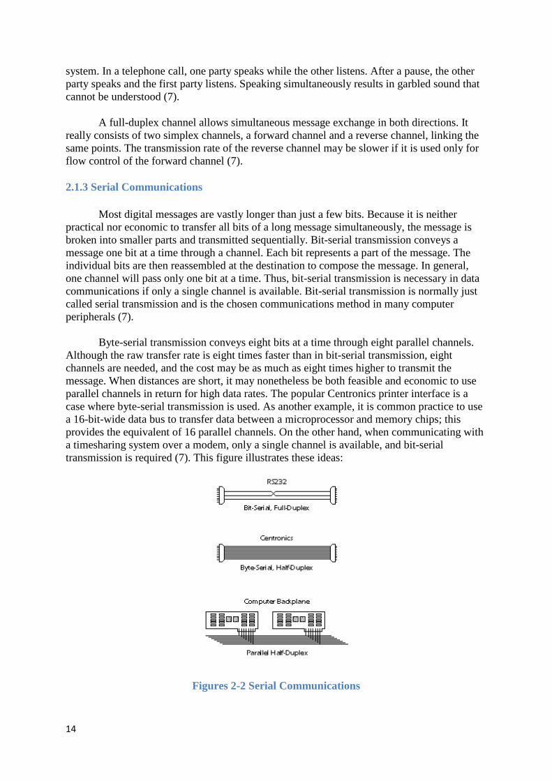
Most digital messages are vastly longer than just a few bits. Because it is neither practical nor economic to transfer all bits of a long message simultaneously, the message is broken into smaller parts and transmitted sequentially. Bit-serial transmission conveys a message one bit at a time through a channel. Each bit represents a part of the message. The individual bits are then reassembled at the destination to compose the message. In general, one channel will pass only one bit at a time. Thus, bit-serial transmission is necessary in data communications if only a single channel is available. Bit-serial transmission is normally just called serial transmission and is the chosen communications method in many computer peripherals (7).
Byte-serial transmission conveys eight bits at a time through eight parallel channels. Although the raw transfer rate is eight times faster than in bit-serial transmission, eight channels are needed, and the cost may be as much as eight times higher to transmit the message. When distances are short, it may nonetheless be both feasible and economic to use parallel channels in return for high data rates. The popular Centronics printer interface is a case where byte-serial transmission is used. As another example, it is common practice to use a 16-bit-wide data bus to transfer data between a microprocessor and memory chips; this provides the equivalent of 16 parallel channels. On the other hand, when communicating with a timesharing system over a modem, only a single channel is available, and bit-serial transmission is required (7). This figure illustrates these ideas:
Figures 2-2 Serial Communications

15
The baud rate refers to the signalling rate at which data is sent through a channel and is measured in electrical transitions per second. In the EIA232 serial interface standard, one signal transition, at most, occurs per bit, and the baud rate and bit rate are identical. In this case, a rate of 9600 baud corresponds to a transfer of 9,600 data bits per second with a bit period of 104 microseconds (1/9600 sec.). If two electrical transitions were required for each bit, as is the case in non-return-to-zero coding, then at a rate of 9600 baud, only 4800 bits per second could be conveyed. The channel efficiency is the number of bits of useful information passed through the channel per second. It does not include framing, formatting, and error detecting bits that may be added to the information bits before a message is transmitted, and will always be less than one (7).
Figures 2-3 EIA232
The data rate of a channel is often specified by its bit rate (often thought erroneously to be the same as baud rate). However, an equivalent measure channel capacity is bandwidth. In general, the maximum data rate a channel can support is directly proportional to the channel's bandwidth and inversely proportional to the channel's noise level (7).
A communications protocol is an agreed-upon convention that defines the order and meaning of bits in a serial transmission. It may also specify a procedure for exchanging messages. A protocol will define how many data bits compose a message unit, the framing and formatting bits, any error-detecting bits that may be added, and other information that governs control of the communications hardware. Channel efficiency is determined by the protocol design rather than by digital hardware considerations. Note that there is a tradeoff between channel efficiency and reliability - protocols that provide greater immunity to noise by adding error-detecting and -correcting codes must necessarily become less efficient (7).
2.1.4 Asynchronous vs. Synchronous Transmission
Serialized data is not generally sent at a uniform rate through a channel. Instead, there is usually a burst of regularly spaced binary data bits followed by a pause, after which the data flow resumes. Packets of binary data are sent in this manner, possibly with variable-length pauses between packets, until the message has been fully transmitted. In order for the receiving end to know the proper moment to read individual binary bits from the channel, it must know exactly when a packet begins and how much time elapses between bits. When this timing information is known, the receiver is said to be synchronized with the transmitter, and accurate data transfer becomes possible. Failure to remain synchronized throughout a transmission will cause data to be corrupted or lost (7).
Two basic techniques are employed to ensure correct synchronization. In synchronous systems, separate channels are used to transmit data and timing information. The timing
16
channel transmits clock pulses to the receiver. Upon receipt of a clock pulse, the receiver reads the data channel and latches the bit value found on the channel at that moment. The data channel is not read again until the next clock pulse arrives. Because the transmitter originates both the data and the timing pulses, the receiver will read the data channel only when told to do so by the transmitter (via the clock pulse), and synchronization is guaranteed (7).
Techniques exist to merge the timing signal with the data so that only a single channel is required. This is especially useful when synchronous transmissions are to be sent through a modem. Two methods in which a data signal is self-timed are nonreturn-to-zero and biphase Manchester coding. These both refer to methods for encoding a data stream into an electrical waveform for transmission (7).
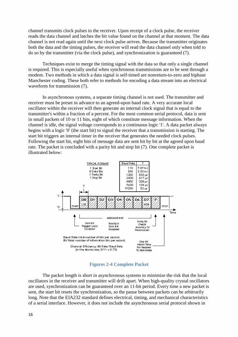
In asynchronous systems, a separate timing channel is not used. The transmitter and receiver must be preset in advance to an agreed-upon baud rate. A very accurate local oscillator within the receiver will then generate an internal clock signal that is equal to the transmitter's within a fraction of a percent. For the most common serial protocol, data is sent in small packets of 10 or 11 bits, eight of which constitute message information. When the channel is idle, the signal voltage corresponds to a continuous logic '1'. A data packet always begins with a logic '0' (the start bit) to signal the receiver that a transmission is starting. The start bit triggers an internal timer in the receiver that generates the needed clock pulses. Following the start bit, eight bits of message data are sent bit by bit at the agreed upon baud rate. The packet is concluded with a parity bit and stop bit (7). One complete packet is illustrated below:
Figures 2-4 Complete Packet
The packet length is short in asynchronous systems to minimize the risk that the local oscillators in the receiver and transmitter will drift apart. When high-quality crystal oscillators are used, synchronization can be guaranteed over an 11-bit period. Every time a new packet is sent, the start bit resets the synchronization, so the pause between packets can be arbitrarily long. Note that the EIA232 standard defines electrical, timing, and mechanical characteristics of a serial interface. However, it does not include the asynchronous serial protocol shown in
17
the previous figure, or the ASCII alphabet described next (7).
2.1.5 The ASCII Character Set
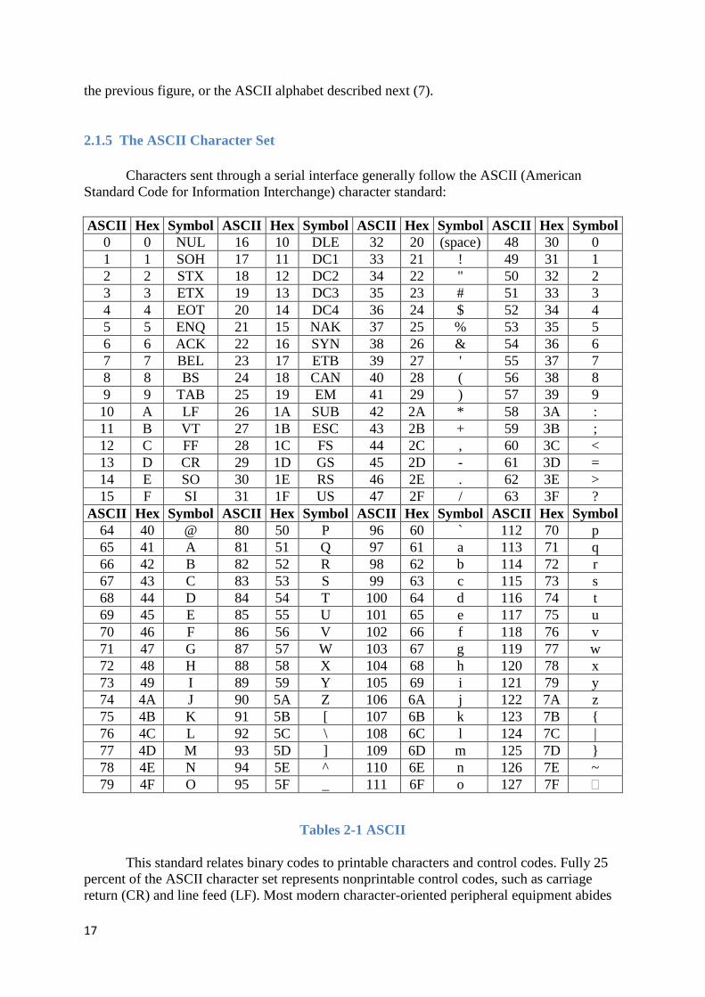
Characters sent through a serial interface generally follow the ASCII (American Standard Code for Information Interchange) character standard:
ASCII Hex Symbol ASCII Hex Symbol ASCII Hex Symbol ASCII Hex Symbol 0 0 NUL 16 10 DLE 32 20 (space) 48 30 0 1 1 SOH 17 11 DC1 33 21 ! 49 31 1 2 2 STX 18 12 DC2 34 22 " 50 32 2 3 3 ETX 19 13 DC3 35 23 # 51 33 3 4 4 EOT 20 14 DC4 36 24 $ 52 34 4 5 5 ENQ 21 15 NAK 37 25 % 53 35 5 6 6 ACK 22 16 SYN 38 26 & 54 36 6 7 7 BEL 23 17 ETB 39 27 ' 55 37 7 8 8 BS 24 18 CAN 40 28 ( 56 38 8 9 9 TAB 25 19 EM 41 29 ) 57 39 9 10 A LF 26 1A SUB 42 2A * 58 3A : 11 B VT 27 1B ESC 43 2B + 59 3B ; 12 C FF 28 1C FS 44 2C , 60 3C < 13 D CR 29 1D GS 45 2D - 61 3D = 14 E SO 30 1E RS 46 2E . 62 3E > 15 F SI 31 1F US 47 2F / 63 3F ?
ASCII Hex Symbol ASCII Hex Symbol ASCII Hex Symbol ASCII Hex Symbol 64 40 @ 80 50 P 96 60 ` 112 70 p 65 41 A 81 51 Q 97 61 a 113 71 q 66 42 B 82 52 R 98 62 b 114 72 r 67 43 C 83 53 S 99 63 c 115 73 s 68 44 D 84 54 T 100 64 d 116 74 t 69 45 E 85 55 U 101 65 e 117 75 u 70 46 F 86 56 V 102 66 f 118 76 v 71 47 G 87 57 W 103 67 g 119 77 w 72 48 H 88 58 X 104 68 h 120 78 x 73 49 I 89 59 Y 105 69 i 121 79 y 74 4A J 90 5A Z 106 6A j 122 7A z 75 4B K 91 5B [ 107 6B k 123 7B { 76 4C L 92 5C \ 108 6C l 124 7C | 77 4D M 93 5D ] 109 6D m 125 7D } 78 4E N 94 5E ^ 110 6E n 126 7E ~ 79 4F O 95 5F _ 111 6F o 127 7F �
Tables 2-1 ASCII
This standard relates binary codes to printable characters and control codes. Fully 25 percent of the ASCII character set represents nonprintable control codes, such as carriage return (CR) and line feed (LF). Most modern character-oriented peripheral equipment abides
18
by the ASCII standard, and thus may be used interchangeably with different computers (7).
2.1.6 Parity and Checksums
Noise and momentary electrical disturbances may cause data to be changed as it passes through a communications channel. If the receiver fails to detect this, the received message will be incorrect, resulting in possibly serious consequences. As a first line of defense against data errors, they must be detected. If an error can be flagged, it might be possible to request that the faulty packet be resent, or to at least prevent the flawed data from being taken as correct. If sufficient redundant information is sent, one- or two-bit errors may be corrected by hardware within the receiver before the corrupted data ever reaches its destination (7).
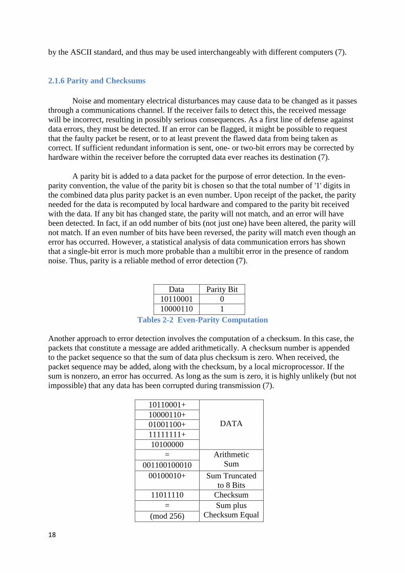
A parity bit is added to a data packet for the purpose of error detection. In the even-parity convention, the value of the parity bit is chosen so that the total number of '1' digits in the combined data plus parity packet is an even number. Upon receipt of the packet, the parity needed for the data is recomputed by local hardware and compared to the parity bit received with the data. If any bit has changed state, the parity will not match, and an error will have been detected. In fact, if an odd number of bits (not just one) have been altered, the parity will not match. If an even number of bits have been reversed, the parity will match even though an error has occurred. However, a statistical analysis of data communication errors has shown that a single-bit error is much more probable than a multibit error in the presence of random noise. Thus, parity is a reliable method of error detection (7).
Data Parity Bit
10110001 0 10000110 1
Tables 2-2 Even-Parity Computation
Another approach to error detection involves the computation of a checksum. In this case, the packets that constitute a message are added arithmetically. A checksum number is appended to the packet sequence so that the sum of data plus checksum is zero. When received, the packet sequence may be added, along with the checksum, by a local microprocessor. If the sum is nonzero, an error has occurred. As long as the sum is zero, it is highly unlikely (but not impossible) that any data has been corrupted during transmission (7).
10110001+
DATA 10000110+ 01001100+ 11111111+ 10100000
= Arithmetic Sum 001100100010
00100010+ Sum Truncated to 8 Bits
11011110 Checksum = Sum plus
Checksum Equal (mod 256)
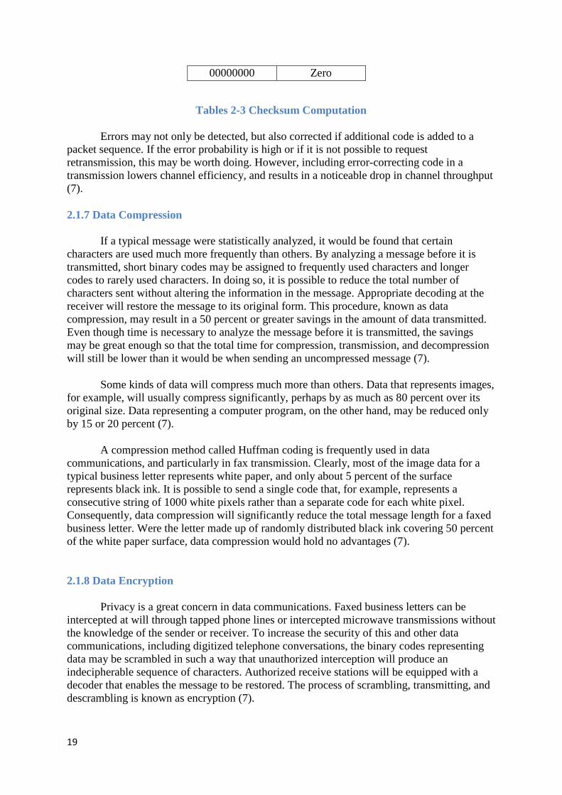
19
00000000 Zero
Tables 2-3 Checksum Computation
Errors may not only be detected, but also corrected if additional code is added to a packet sequence. If the error probability is high or if it is not possible to request retransmission, this may be worth doing. However, including error-correcting code in a transmission lowers channel efficiency, and results in a noticeable drop in channel throughput (7).
2.1.7 Data Compression
If a typical message were statistically analyzed, it would be found that certain characters are used much more frequently than others. By analyzing a message before it is transmitted, short binary codes may be assigned to frequently used characters and longer codes to rarely used characters. In doing so, it is possible to reduce the total number of characters sent without altering the information in the message. Appropriate decoding at the receiver will restore the message to its original form. This procedure, known as data compression, may result in a 50 percent or greater savings in the amount of data transmitted. Even though time is necessary to analyze the message before it is transmitted, the savings may be great enough so that the total time for compression, transmission, and decompression will still be lower than it would be when sending an uncompressed message (7).
Some kinds of data will compress much more than others. Data that represents images, for example, will usually compress significantly, perhaps by as much as 80 percent over its original size. Data representing a computer program, on the other hand, may be reduced only by 15 or 20 percent (7).
A compression method called Huffman coding is frequently used in data communications, and particularly in fax transmission. Clearly, most of the image data for a typical business letter represents white paper, and only about 5 percent of the surface represents black ink. It is possible to send a single code that, for example, represents a consecutive string of 1000 white pixels rather than a separate code for each white pixel. Consequently, data compression will significantly reduce the total message length for a faxed business letter. Were the letter made up of randomly distributed black ink covering 50 percent of the white paper surface, data compression would hold no advantages (7).
2.1.8 Data Encryption
Privacy is a great concern in data communications. Faxed business letters can be intercepted at will through tapped phone lines or intercepted microwave transmissions without the knowledge of the sender or receiver. To increase the security of this and other data communications, including digitized telephone conversations, the binary codes representing data may be scrambled in such a way that unauthorized interception will produce an indecipherable sequence of characters. Authorized receive stations will be equipped with a decoder that enables the message to be restored. The process of scrambling, transmitting, and descrambling is known as encryption (7).
20
Custom integrated circuits have been designed to perform this task and are available at low cost. In some cases, they will be incorporated into the main circuitry of a data communications device and function without operator knowledge. In other cases, an external circuit is used so that the device, and its encrypting/decrypting technique, may be transported easily (7).
2.1.9 Data Storage Technology Normally, we think of communications science as dealing with the contemporaneous
exchange of information between distant parties. However, many of the same techniques employed in data communications are also applied to data storage to ensure that the retrieval of information from a storage medium is accurate. We find, for example, that similar kinds of error-correcting codes used to protect digital telephone transmissions from noise are also used to guarantee correct readback of digital data from compact audio disks, CD-ROMs, and tape backup systems (7).
2.1.10 Data Transfer in Digital Circuits
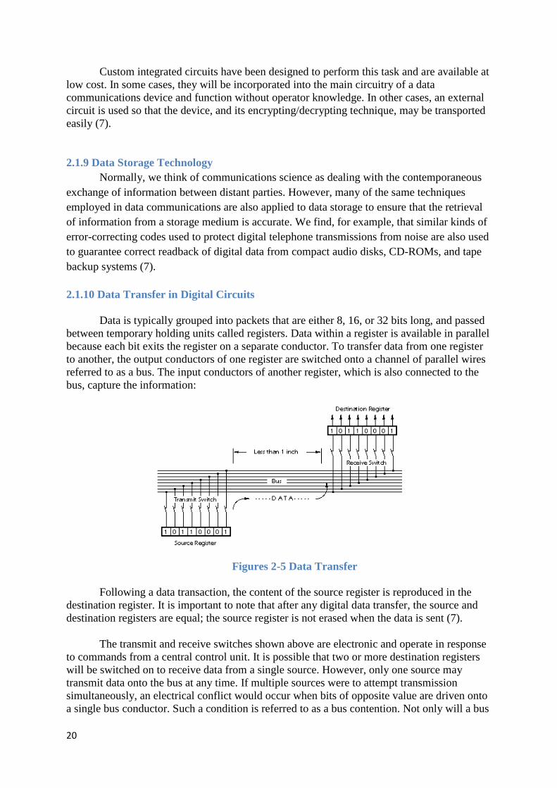
Data is typically grouped into packets that are either 8, 16, or 32 bits long, and passed between temporary holding units called registers. Data within a register is available in parallel because each bit exits the register on a separate conductor. To transfer data from one register to another, the output conductors of one register are switched onto a channel of parallel wires referred to as a bus. The input conductors of another register, which is also connected to the bus, capture the information:
Figures 2-5 Data Transfer
Following a data transaction, the content of the source register is reproduced in the destination register. It is important to note that after any digital data transfer, the source and destination registers are equal; the source register is not erased when the data is sent (7).
The transmit and receive switches shown above are electronic and operate in response to commands from a central control unit. It is possible that two or more destination registers will be switched on to receive data from a single source. However, only one source may transmit data onto the bus at any time. If multiple sources were to attempt transmission simultaneously, an electrical conflict would occur when bits of opposite value are driven onto a single bus conductor. Such a condition is referred to as a bus contention. Not only will a bus

21
contention result in the loss of information, but it also may damage the electronic circuitry. As long as all registers in a system are linked to one central control unit, bus contentions should never occur if the circuit has been designed properly. Note that the data buses within a typical microprocessor are funda-mentally half-duplex channels (7).
2.1.11 Transmission over Short Distances (< 2 feet) When the source and destination registers are part of an integrated circuit (within a
microprocessor chip, for example), they are extremely close (thousandths of an inch). Consequently, the bus signals are at very low power levels, may traverse a distance in very little time, and are not very susceptible to external noise and distortion. This is the ideal environment for digital communications. However, it is not yet possible to integrate all the necessary circuitry for a computer (i.e., CPU, memory, disk control, video and display drivers, etc.) on a single chip. When data is sent off-chip to another integrated circuit, the bus signals must be amplified and conductors extended out of the chip through external pins (7). Amplifiers may be added to the source register:
Figures 2-6 Source Register
Bus signals that exit microprocessor chips and other VLSI circuitry are electrically capable of traversing about one foot of conductor on a printed circuit board, or less if many devices are connected to it. Special buffer circuits may be added to boost the bus signals sufficiently for transmission over several additional feet of conductor length, or for distribution to many other chips (such as memory chips) (7).
2.1.12 Noise and Electrical Distortion Because of the very high switching rate and relatively low signal strength found on
data, address, and other buses within a computer, direct extension of the buses beyond the confines of the main circuit board or plug-in boards would pose serious problems (7). First, long runs of electrical conductors, either on printed circuit boards or through cables, act like receiving antennas for electrical noise radiated by motors, switches, and electronic circuits:
22
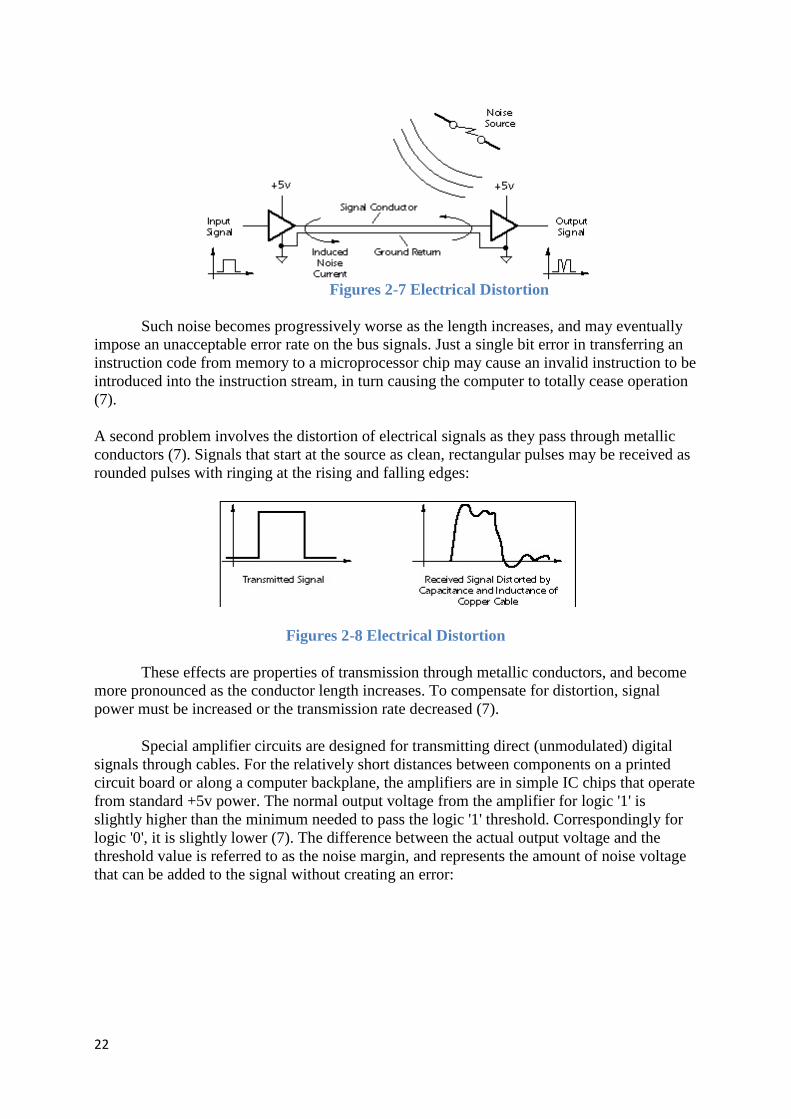
Figures 2-7 Electrical Distortion
Such noise becomes progressively worse as the length increases, and may eventually impose an unacceptable error rate on the bus signals. Just a single bit error in transferring an instruction code from memory to a microprocessor chip may cause an invalid instruction to be introduced into the instruction stream, in turn causing the computer to totally cease operation (7). A second problem involves the distortion of electrical signals as they pass through metallic conductors (7). Signals that start at the source as clean, rectangular pulses may be received as rounded pulses with ringing at the rising and falling edges:
Figures 2-8 Electrical Distortion
These effects are properties of transmission through metallic conductors, and become more pronounced as the conductor length increases. To compensate for distortion, signal power must be increased or the transmission rate decreased (7).
Special amplifier circuits are designed for transmitting direct (unmodulated) digital signals through cables. For the relatively short distances between components on a printed circuit board or along a computer backplane, the amplifiers are in simple IC chips that operate from standard +5v power. The normal output voltage from the amplifier for logic '1' is slightly higher than the minimum needed to pass the logic '1' threshold. Correspondingly for logic '0', it is slightly lower (7). The difference between the actual output voltage and the threshold value is referred to as the noise margin, and represents the amount of noise voltage that can be added to the signal without creating an error:

23
Figures 2-9 Noise Voltage
2.1.13 Transmission over Medium Distances (< 20 feet)
Computer peripherals such as a printer or scanner generally include mechanisms that cannot be situated within the computer itself. Our first thought might be just to extend the computer's internal buses with a cable of sufficient length to reach the peripheral. Doing so, however, would expose all bus transactions to external noise and distortion even though only a very small percentage of these transactions concern the distant peripheral to which the bus is connected (7).
If a peripheral can be located within 20 feet of the computer, however, relatively simple electronics may be added to make data transfer through a cable efficient and reliable. To accomplish this, a bus interface circuit is installed in the computer:
Figures 2-10 Interface circuit is installed
It consists of a holding register for peripheral data, timing and formatting circuitry for external data transmission, and signal amplifiers to boost the signal sufficiently for transmission through a cable. When communication with the peripheral is necessary, data is first deposited in the holding register by the microprocessor. This data will then be reformatted, sent with error-detecting codes, and transmitted at a relatively slow rate by digital hardware in the bus interface circuit. In addition, the signal power is greatly boosted before transmission through the cable. These steps ensure that the data will not be corrupted by noise or distortion during its passage through the cable. In addition, because only data destined for the peripheral is sent, the party-line transactions taking place on the computer's buses are not unnecessarily exposed to noise (7).
24
Data sent in this manner may be transmitted in byte-serial format if the cable has eight parallel channels (at least 10 conductors for half-duplex operation), or in bit-serial format if only a single channel is available (7).
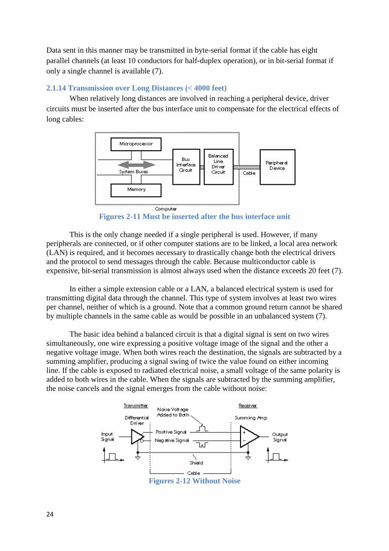
2.1.14 Transmission over Long Distances (< 4000 feet) When relatively long distances are involved in reaching a peripheral device, driver
circuits must be inserted after the bus interface unit to compensate for the electrical effects of long cables:
Figures 2-11 Must be inserted after the bus interface unit
This is the only change needed if a single peripheral is used. However, if many peripherals are connected, or if other computer stations are to be linked, a local area network (LAN) is required, and it becomes necessary to drastically change both the electrical drivers and the protocol to send messages through the cable. Because multiconductor cable is expensive, bit-serial transmission is almost always used when the distance exceeds 20 feet (7).
In either a simple extension cable or a LAN, a balanced electrical system is used for transmitting digital data through the channel. This type of system involves at least two wires per channel, neither of which is a ground. Note that a common ground return cannot be shared by multiple channels in the same cable as would be possible in an unbalanced system (7).
The basic idea behind a balanced circuit is that a digital signal is sent on two wires simultaneously, one wire expressing a positive voltage image of the signal and the other a negative voltage image. When both wires reach the destination, the signals are subtracted by a summing amplifier, producing a signal swing of twice the value found on either incoming line. If the cable is exposed to radiated electrical noise, a small voltage of the same polarity is added to both wires in the cable. When the signals are subtracted by the summing amplifier, the noise cancels and the signal emerges from the cable without noise:
Figures 2-12 Without Noise

25
A great deal of technology has been developed for LAN systems to minimize the amount of cable required and maximize the throughput. The costs of a LAN have been concentrated in the electrical interface card that would be installed in PCs or peripherals to drive the cable, and in the communications software, not in the cable itself (whose cost has been minimized). Thus, the cost and complexity of a LAN are not particularly affected by the distance between stations (7).
2.1.15 Transmission over Very Long Distances (greater than 4000 feet) Data communications through the telephone network can reach any point in the world.
The volume of overseas fax transmissions is increasing constantly, and computer networks that link thousands of businesses, governments, and universities are pervasive. Transmissions over such distances are not generally accomplished with a direct-wire digital link, but rather with digitally-modulated analog carrier signals. This technique makes it possible to use existing analog telephone voice channels for digital data, although at considerably reduced data rates compared to a direct digital link (7).
Transmission of data from your personal computer to a timesharing service over phone lines requires that data signals be converted to audible tones by a modem. An audio sine wave carrier is used, and, depending on the baud rate and protocol, will encode data by varying the frequency, phase, or amplitude of the carrier. The receiver's modem accepts the modulated sine wave and extracts the digital data from it. Several modulation techniques typically used in encoding digital data for analog transmission are shown below:
Figures 2-13 Several modulation techniques
Similar techniques may be used in digital storage devices such as hard disk drives to encode data for storage using an analog medium (7).
26
2.2 Computer Networks A computer network is an interconnected collection of autonomous computers. The
goals of a computer network include:
• Resource sharing: programs (O.S., applications), data, equipment (printers, disks) are available to all users of the network regardless of location (6).
• High reliability: By replicating files on different machines and having spare cpus, users are more immune from hardware/software failure (6).
• Less cost: Small machines have about 1/10 the power of a mainframe but 1/1000 the cost. By using such machines with file server machine(s), a local area network LAN can be cheaply installed. It is easy to increase the capacity by adding new machines (6).
• Communications medium: Users have access to email and the Internet (6).
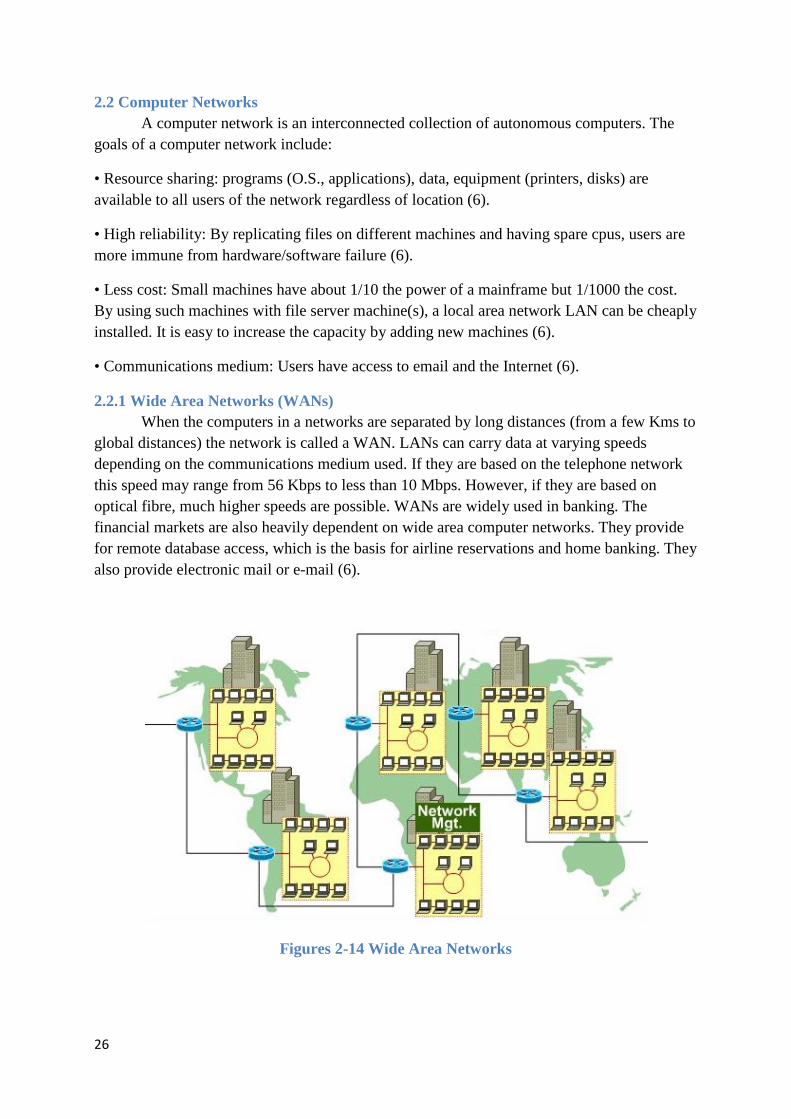
2.2.1 Wide Area Networks (WANs) When the computers in a networks are separated by long distances (from a few Kms to
global distances) the network is called a WAN. LANs can carry data at varying speeds depending on the communications medium used. If they are based on the telephone network this speed may range from 56 Kbps to less than 10 Mbps. However, if they are based on optical fibre, much higher speeds are possible. WANs are widely used in banking. The financial markets are also heavily dependent on wide area computer networks. They provide for remote database access, which is the basis for airline reservations and home banking. They also provide electronic mail or e-mail (6).
Figures 2-14 Wide Area Networks
27
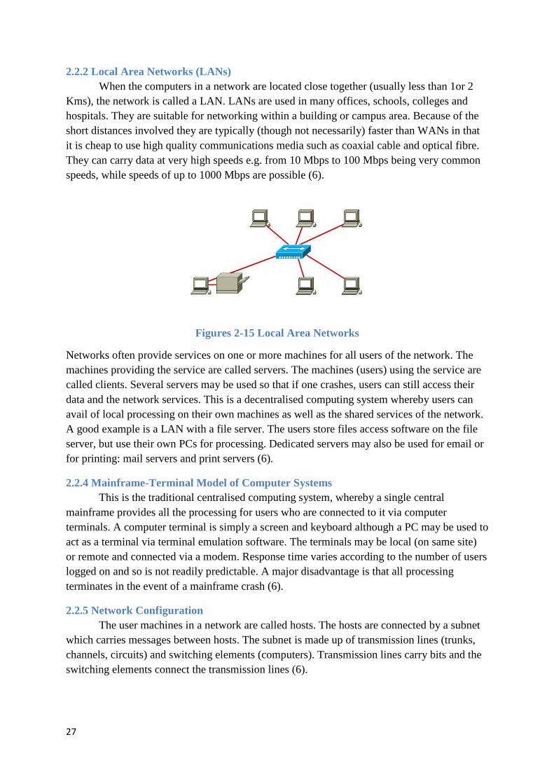
2.2.2 Local Area Networks (LANs) When the computers in a network are located close together (usually less than 1or 2
Kms), the network is called a LAN. LANs are used in many offices, schools, colleges and hospitals. They are suitable for networking within a building or campus area. Because of the short distances involved they are typically (though not necessarily) faster than WANs in that it is cheap to use high quality communications media such as coaxial cable and optical fibre. They can carry data at very high speeds e.g. from 10 Mbps to 100 Mbps being very common speeds, while speeds of up to 1000 Mbps are possible (6).
Figures 2-15 Local Area Networks
Networks often provide services on one or more machines for all users of the network. The machines providing the service are called servers. The machines (users) using the service are called clients. Several servers may be used so that if one crashes, users can still access their data and the network services. This is a decentralised computing system whereby users can avail of local processing on their own machines as well as the shared services of the network. A good example is a LAN with a file server. The users store files access software on the file server, but use their own PCs for processing. Dedicated servers may also be used for email or for printing: mail servers and print servers (6).
2.2.4 Mainframe-Terminal Model of Computer Systems This is the traditional centralised computing system, whereby a single central
mainframe provides all the processing for users who are connected to it via computer terminals. A computer terminal is simply a screen and keyboard although a PC may be used to act as a terminal via terminal emulation software. The terminals may be local (on same site) or remote and connected via a modem. Response time varies according to the number of users logged on and so is not readily predictable. A major disadvantage is that all processing terminates in the event of a mainframe crash (6).
2.2.5 Network Configuration The user machines in a network are called hosts. The hosts are connected by a subnet
which carries messages between hosts. The subnet is made up of transmission lines (trunks, channels, circuits) and switching elements (computers). Transmission lines carry bits and the switching elements connect the transmission lines (6).
28
The shape of a computer network can vary conceptually from a single straight line, usually referred to as a bus, to a many sided polygon with each node connected to all the others (6).
There are two types of subnet design:
1. Broadcast subnets: In this system a message is broadcast over the network and all machines have the possibility of receiving the message. LANs usually use broadcast subnets. Each machine has its own unique address and typically will only "listen" to messages that are sent to this address (6).
2. Point to Point subnets: Here, a message is transmitted from one computer to another computer and so until the destination computer is reached. This is analogous to the postal system where a letter is transferred from post-office to post-office. WANs usually use point to point subnets (6).
2.2.6 Broadcast Sub-networks These are typically configured as either a bus or a ring network. They can be further
classified as Static or Dynamic (6).
In a static broadcast subnet each computer gets a chance to transmit and can only broadcast a message when it's turn comes around. This is a rather inefficient use of network time, since if the computer, whose turn it is to transmit, has nothing to transmit, then the network is left idle. It has the advantage that two stations can never transmit a message simultaneously. A simultaneous transmission of messages causes a collision where the messages get corrupted and so are not received. They must be re-transmitted (6).
A dynamic broadcast subnet makes more efficient use of the network. This system allows any station to transmit at any time the network is free of traffic. In this case, when a computer wishes to transmit, it follows the following protocol:
1. Listen to see if the network is free (Carrier Sense) (6)
2. If the network is free, transmit the message otherwise wait for a small amount of time and repeat from step 1 (6).
3. Check to see if the message is still on the network (Collision Detect). Two machines could have carried out step 1 at same time, found the network free and proceeded to transmit their messages, thus causing a collision. If a collision is detected then wait for arandom but small amount of time and repeat from step 1. In the event of a collision, both computers will wait for random time periods so that it is unlikely that they will cause another collision. The likelihood of collisions is directly related to the number of active users on the network i.e. the network traffic.The above protocol is referred to as CSMA/CD, which stands for Carrier Sense Multiple Access/Collision Detect. Multiple Access means that many users can access the network at any time (6).

29
2.2.7 Point to Point Networks The second type of subnet, the point to point subnet, is mainly found in Wide Area
Networks (WANs). If possible, the point to point subnet transmits directly to the relevant station. If no direct route is available, it will send the message to a "switch" which re-transmits the message to the destination. The best known example of this type of network is the telephone network (Public Switched Telephone Network or PSTN. also referred to as the Plain Old Telephone System or POTS) (6)
2.3 Network Topology The physical topology of a network refers to the configuration of cables, computers,
and other peripherals. Physical topology should not be confused with logical topology which is the method used to pass information between workstations. Logical topology was discussed in the Protocol chapter (8).
Main Types of Network Topologies In networking, the term "topology" refers to the layout of connected devices on a network. This article introduces the standard topologies of computer networking (8).
One can think of a topology as a network's virtual shape or structure. This shape does not necessarily correspond to the actual physical layout of the devices on the network. For example, the computers on a home LAN may be arranged in a circle in a family room, but it would be highly unlikely to find an actual ring topology there (8).
Network topologies are categorized into the following basic types:
• Star Topology • Ring Topology • Bus Topology • Tree Topology • Mesh Topology • Hybrid Topology
More complex networks can be built as hybrids of two or more of the above basic topologies (8).

30
Figures 2-16Network Topology
2.3.1 Star Topology Many home networks use the star topology. A star network features a central
connection point called a "hub" that may be a hub, switch or router. Devices typically connect to the hub with Unshielded Twisted Pair (UTP) Ethernet (8).
Compared to the bus topology, a star network generally requires more cable, but a failure in any star network cable will only take down one computer's network access and not the entire LAN. (If the hub fails, however, the entire network also fails.) (8)
Figures 2-17Star Topology

31
Advantages of a Star Topology
• Easy to install and wire. • No disruptions to the network then connecting or removing devices. • Easy to detect faults and to remove parts.
Disadvantages of a Star Topology
• Requires more cable length than a linear topology. • If the hub or concentrator fails, nodes attached are disabled. • More expensive than linear bus topologies because of the cost of the concentrators.
The protocols used with star configurations are usually Ethernet or LocalTalk. Token Ring uses a similar topology, called the star-wired ring (8).
2.3.2 Star-Wired Ring A star-wired ring topology may appear (externally) to be the same as a star topology.
Internally, the MAU of a star-wired ring contains wiring that allows information to pass from one device to another in a circle or ring (See fig. 3). The Token Ring protocol uses a star-wired ring topology (8).
2.3.3 Ring Topology In a ring network, every device has exactly two neighbors for communication purposes. All messages travel through a ring in the same direction (either "clockwise" or "counterclockwise"). A failure in any cable or device breaks the loop and can take down the entire network. To implement a ring network, one typically uses FDDI, SONET, or Token Ring technology. Ring topologies are found in some office buildings or school campuses (8).
Figures 2-18 Ring Topology

32
2.3.4 Bus Topology Bus networks (not to be confused with the system bus of a computer) use a common
backbone to connect all devices. A single cable, the backbone functions as a shared communication medium that devices attach or tap into with an interface connector. A device wanting to communicate with another device on the network sends a broadcast message onto the wire that all other devices see, but only the intended recipient actually accepts and processes the message (8).
Ethernet bus topologies are relatively easy to install and don't require much cabling compared to the alternatives. 10Base-2 ("ThinNet") and 10Base-5 ("ThickNet") both were popular Ethernet cabling options many years ago for bus topologies. However, bus networks work best with a limited number of devices. If more than a few dozen computers are added to a network bus, performance problems will likely result. In addition, if the backbone cable fails, the entire network effectively becomes unusable (8).
Figures 2-19 Bus Network Topology
Advantages of a Linear Bus Topology
• Easy to connect a computer or peripheral to a linear bus. • Requires less cable length than a star topology.
Disadvantages of a Linear Bus Topology
• Entire network shuts down if there is a break in the main cable. • Terminators are required at both ends of the backbone cable. • Difficult to identify the problem if the entire network shuts down. • Not meant to be used as a stand-alone solution in a large building.
(8)
2.3.5 Tree Topology Tree topologies integrate multiple star topologies together onto a bus. In its simplest
form, only hub devices connect directly to the tree bus, and each hub functions as the "root" of a tree of devices. This bus/star hybrid approach supports future expandability of the

33
network much better than a bus (limited in the number of devices due to the broadcast traffic it generates) or a star (limited by the number of hub connection points) alone (8).
Figures 2-20 Tree Network Topology
Advantages of a Tree Topology
• Point-to-point wiring for individual segments. • Supported by several hardware and software venders.
Disadvantages of a Tree Topology
• Overall length of each segment is limited by the type of cabling used. • If the backbone line breaks, the entire segment goes down. • More difficult to configure and wire than other topologies.
(8)
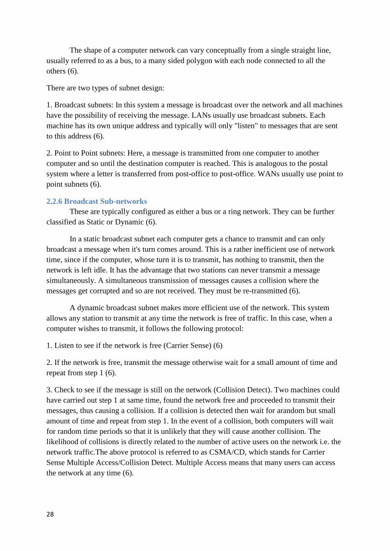
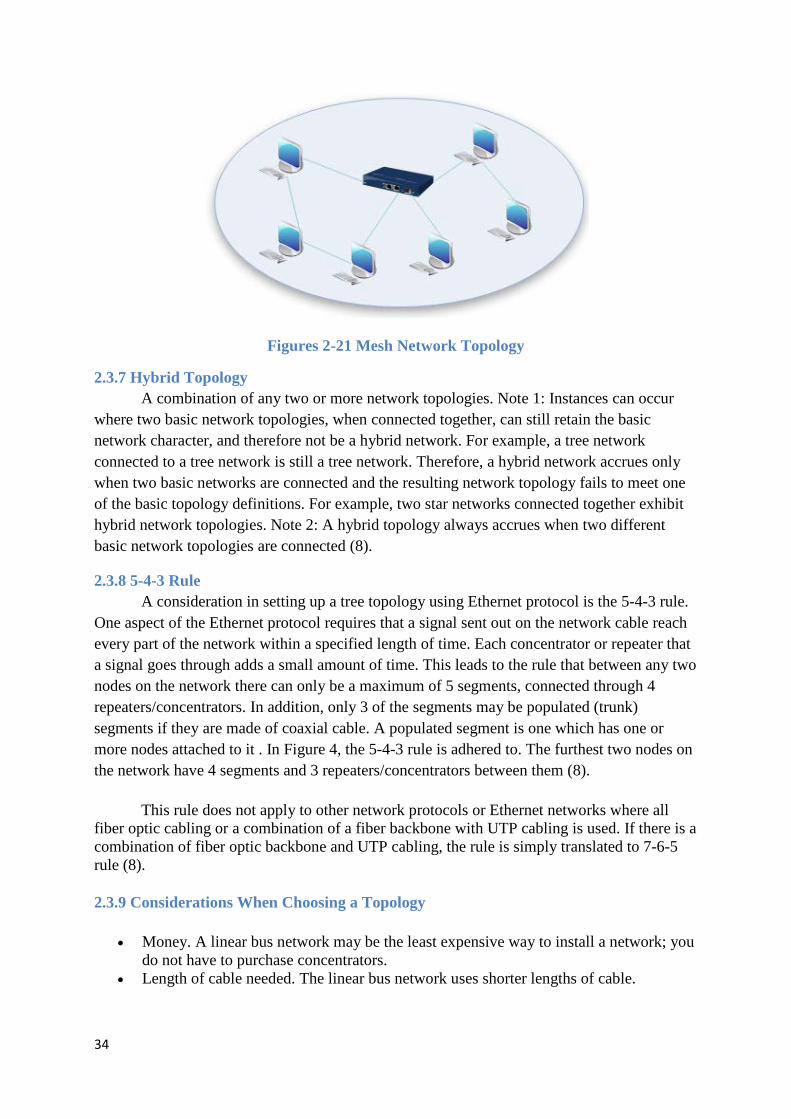
2.3.6 Mesh Topology Mesh topologies involve the concept of routes. Unlike each of the previous topologies,
messages sent on a mesh network can take any of several possible paths from source to destination. (Recall that even in a ring, although two cable paths exist, messages can only travel in one direction.) Some WANs, most notably the Internet, employ mesh routing (8).
A mesh network in which every device connects to every other is called a full mesh. As shown in the illustration below, partial mesh networks also exist in which some devices connect only indirectly to others (8).
34
Figures 2-21 Mesh Network Topology
2.3.7 Hybrid Topology A combination of any two or more network topologies. Note 1: Instances can occur
where two basic network topologies, when connected together, can still retain the basic network character, and therefore not be a hybrid network. For example, a tree network connected to a tree network is still a tree network. Therefore, a hybrid network accrues only when two basic networks are connected and the resulting network topology fails to meet one of the basic topology definitions. For example, two star networks connected together exhibit hybrid network topologies. Note 2: A hybrid topology always accrues when two different basic network topologies are connected (8).
2.3.8 5-4-3 Rule A consideration in setting up a tree topology using Ethernet protocol is the 5-4-3 rule.
One aspect of the Ethernet protocol requires that a signal sent out on the network cable reach every part of the network within a specified length of time. Each concentrator or repeater that a signal goes through adds a small amount of time. This leads to the rule that between any two nodes on the network there can only be a maximum of 5 segments, connected through 4 repeaters/concentrators. In addition, only 3 of the segments may be populated (trunk) segments if they are made of coaxial cable. A populated segment is one which has one or more nodes attached to it . In Figure 4, the 5-4-3 rule is adhered to. The furthest two nodes on the network have 4 segments and 3 repeaters/concentrators between them (8).
This rule does not apply to other network protocols or Ethernet networks where all fiber optic cabling or a combination of a fiber backbone with UTP cabling is used. If there is a combination of fiber optic backbone and UTP cabling, the rule is simply translated to 7-6-5 rule (8).
2.3.9 Considerations When Choosing a Topology
• Money. A linear bus network may be the least expensive way to install a network; you do not have to purchase concentrators.
• Length of cable needed. The linear bus network uses shorter lengths of cable.

35
• Future growth. With a star topology, expanding a network is easily done by adding another concentrator.
• Cable type. The most common cable in schools is unshielded twisted pair, which is most often used with star topologies.
(8)
2.3.10 Other definition of Network Topology A network consists of multiple computers connected using some type of interface,
each having one or more interface devices such as a Network Interface Card (NIC) and/or a serial device for PPP networking. Each computer is supported by network software that provides the server or client functionality. The hardware used to transmit data across the network is called the media. It may include copper cable, fiber optic, or wireless transmission. The standard cabling used for the purposes of this document is 10Base-T category 5 Ethernet cable. This is twisted copper cabling which appears at the surface to look similar to TV coaxial cable. It is terminated on each end by a connector that looks much like a phone connector. Its maximum segment length is 100 meters (8).
In a server based network, there are computers set up to be primary providers of services such as file service or mail service. The computers providing the service are are called servers and the computers that request and use the service are called client computers (8).
In a peer-to-peer network, various computers on the network can act both as clients and servers. For instance, many Microsoft Windows based computers will allow file and print sharing. These computers can act both as a client and a server and are also referred to as peers. Many networks are combination peer-to-peer and server based networks. The network operating system uses a network data protocol to communicate on the network to other computers. The network operating system supports the applications on that computer. A Network Operating System (NOS) includes Windows NT, Novell Netware, Linux, Unix and others (8).
2.4 OSI Reference Model
2.4.1 Network Reference Models A computer network connects two or more devices together to share information and
services. Multiple networks connected together form an internetwork. Internetworking present challenges - interoperating between products from different manufacturers requires consistent standards. Network reference models were developed to address these challenges. A network reference model serves as a blueprint, detailing how communication between network devices should occur (9).
The two most recognized network reference models are:
• The Open Systems Interconnection (OSI) model • The Department of Defense (DoD) model

36
Without the framework that network models provide, all network hardware and software would have been proprietary. Organizations would have been locked into a single vendor’s equipment, and global networks like the Internet would have been impractical, if not impossible. Network models are organized into layers, with each layer representing a specific networking function. These functions are controlled by protocols, which are rules that govern end-to-end communication between devices. Protocols on one layer will interact with protocols on the layer above and below it, forming a protocol suite or stack. The TCP/IP suite is the most prevalent protocol suite, and is the foundation of the Internet. A network model is not a physical entity – there is no OSI device. Manufacturers do not always strictly adhere to a reference model’s blueprint, and thus not every protocol fits perfectly within a single layer. Some protocols can function across multiple layers (9).
2.4.2 OSI Reference Model The Open Systems Interconnection (OSI) model was developed by the International
Organization for Standardization (ISO), and formalized in 1984. It provided the first framework governing how information should be sent across a network. The OSI model consists of seven layers, each corresponding to a specific network function:
7. Application 6. Presention
5. Session 4. Transport 3.Network
2. Data-link 1.Physical
Tables 2-4 OSI Model Layers
ISO further developed an entire protocol suite based on the OSI model; however, the
OSI protocol suite was never widely implemented. The OSI model itself is now somewhat deprecated – modern protocol suites, such as the TCP/IP suite, are difficult to fit cleanly within the OSI model’s seven layers. This is especially true of the upper three layers. The bottom (or lower) four layers are more clearly defined, and terminology from those layers is still prevalently used. Many protocols and devices are described by which lower layer they operate at. (9)
2.4.3 OSI Model - The Upper Layers The top three layers of the OSI model are often referred to as the upper layers:
• Layer-7 - Application layer • Layer-6 - Presentation layer • Layer-5 - Session layer

37
Protocols that operate at these layers manage application-level functions, and are generally implemented in software. The function of the upper layers of the OSI model can be difficult to visualize. Upper layer protocols do not always fit perfectly within a layer, and often function across multiple layers. (9)
2.4.4 OSI Model - The Application Layer The Application layer (Layer-7) provides the interface between the user application
and the network. A web browser and an email client are examples of user applications. The user application itself does not reside at the Application layer – the protocol does. The user interacts with the application, which in turn interacts with the application protocol (9).
Examples of Application layer protocols include:
• FTP, via an FTP client • HTTP, via a web browser • POP3 and SMTP, via an email client • Telnet
The Application layer provides a variety of functions:
• Identifies communication partners • Determines resource availability • Synchronizes communication
The Application layer interacts with the Presentation layer below it. As it is the top-most layer, it does not interact with any layers above it (9).
2.4.5 OSI Model - The Presentation Layer The Presentation layer (Layer-6) controls the formatting and syntax of user data for the
application layer. This ensures that data from the sending application can be understood by the receiving application. Standards have been developed for the formatting of data types, such as text, images, audio, and video. Examples of Presentation layer formats include:
• Text - RTF, ASCII, EBCDIC • Images - GIF, JPG, TIF • Audio - MIDI, MP3, WAV • Movies - MPEG, AVI, MOV
If two devices do not support the same format or syntax, the Presentation layer can provide conversion or translation services to facilitate communication. Additionally, the Presentation layer can perform encryption and compression of data, as required. However, these functions can also be performed at lower layers as well. For example, the Network layer can perform encryption, using IPSec (9).

38
2.4.6 OSI Model - The Session Layer The Session layer (Layer-5) is responsible for establishing, maintaining, and
ultimately terminating sessions between devices. If a session is broken, this layer can attempt to recover the session (9).
Sessions communication falls under one of three categories:
• Full-Duplex – simultaneous two-way communication • Half-Duplex – two-way communication, but not simultaneous • Simplex – one-way communication
Many modern protocol suites, such as TCP/IP, do not implement Session layer protocols. Connection management is often controlled by lower layers, such as the Transport layer. The lack of true Session layer protocols can present challenges for highavailability and failover. Reliance on lower-layer protocols for session management offers less flexibility than a strict adherence to the OSI model (9).
2.4.7 OSI Model - The Lower Layers The bottom four layers of the OSI model are often referred to as the lower layers:
• Layer-4 – Transport layer • Layer-3 – Network layer • Layer-2 – Data-Link layer • Layer-1 – Physical layer
Protocols that operate at these layers control the end-to-end transport of data between devices, and are implemented in both software and hardware (9).
2.4.8 OSI Model - The Transport Layer The Transport layer (Layer-4) does not actually send data, despite its name. Instead,
this layer is responsible for the reliable transfer of data, by ensuring that data arrives at its destination error-free and in order (9).
Transport layer communication falls under two categories:
• Connection-oriented – requires that a connection with specific agreed-upon parameters be established before data is sent.
• Connectionless – requires no connection before data is sent. Connection-oriented protocols provide several important services:
• Segmentation and sequencing – data is segmented into smaller pieces for transport. Each segment is assigned a sequence number, so that the receiving device can reassemble the data on arrival.
• Connection establishment – connections are established, maintained, and ultimately terminated between devices.
• Acknowledgments – receipt of data is confirmed through the use of acknowledgments. Otherwise, data is retransmitted, guaranteeing delivery.

39
• Flow control (or windowing) – data transfer rate is negotiated to prevent congestion.
The TCP/IP protocol suite incorporates two Transport layer protocols:
• Transmission Control Protocol (TCP) – connection-oriented • User Datagram Protocol (UDP) – connectionless
(9)
2.4.9 OSI Model - The Network Layer The Network layer (Layer-3) controls internetwork communication, and has two key
responsibilities:
• Logical addressing – provides a unique address that identifies both the host, and the network that host exists on.
• Routing – determines the best path to a particular destination network, and then routes data accordingly.
Two of the most common Network layer protocols are:
• Internet Protocol (IP) • Novell’s Internetwork Packet Exchange (IPX).
IPX is almost entirely deprecated. IP version 4 (IPv4) and IP version 6 (IPv6) are covered in nauseating detail in other guides. (9)
2.4.10 OSI Model - The Data-Link Layer While the Network layer is concerned with transporting data between networks, the Data-
Link layer (Layer-2) is responsible for transporting data within a network. The Data-Link layer consists of two sublayers:
• Logical Link Control (LLC) sublayer • Media Access Control (MAC) sublayer
The LLC sublayer serves as the intermediary between the physical link and all higher layer protocols. It ensures that protocols like IP can function regardless of what type of physical technology is being used. Additionally, the LLC sublayer can perform flow-control and errorchecking, though such functions are often provided by Transport layer protocols, such as TCP. The MAC sublayer controls access to the physical medium, serving asmediator if multiple devices are competing for the same physical link. Datalink layer technologies have various methods of accomplishing this - Ethernet uses Carrier Sense Multiple Access with Collision Detection (CSMA/CD), and Token Ring utilizes a token. Ethernet is covered in great detail in another guide. The Data-link layer packages the higher-layer data into frames, so that the data can be put onto the physical wire. This packaging process is referred to as framing or encapsulation. The encapsulation type will vary depending on the underlying technology (9).
Common Data-link layer technologies include following:
40
• Ethernet – the most common LAN data-link technology • Token Ring – almost entirely deprecated • FDDI (Fiber Distributed Data Interface) • 802.11 Wireless • Frame-Relay • ATM (Asynchronous Transfer Mode)
The data-link frame contains the source and destination hardware (or physical) address. Hardware addresses uniquely identify a host within a network, and are often hardcoded onto physical network interfaces. However, hardware addresses contain no mechanism for differentiating one network from another, and can only identify a host within a network. The most common hardware address is the Ethernet MAC address (9).
2.4.11 OSI Model - The Physical Layer The Physical layer (Layer-1) controls the signaling and transferring of raw bits onto
the physical medium. The Physical layer is closely related to the Data-link layer, as many technologies (such as Ethernet) contain both datalink and physical functions (9).
The Physical layer provides specifications for a variety of hardware:
• Cabling • Connectors and transceivers • Network interface cards (NICs) • Wireless radios • Hubs
Physical-layer devices and topologies are covered extensively in other guides (9).
2.4.12 Encapsulation and Layered Communication As data is passed from the user application down the virtual layers of the OSI model,
each layer adds a header (and sometimes a trailer) containing protocol information specific to that layer. These headers are called Protocol Data Units (PDUs), and the process of adding these headers is called encapsulation. Note that in the TCP/IP protocol suite only the lower layers perform encapsulation, generally (9).
For example, a Transport layer protocol such as TCP will add a header containing flow control, port numbers, and sequencing. The Network layer header contains logical addressing information, and the Data-link header contains physical addressing and other hardware specific information (9).
The PDU of each layer is identified with a different term:
Layer PDU Name Application - Presentation -
Session - Transport Segments
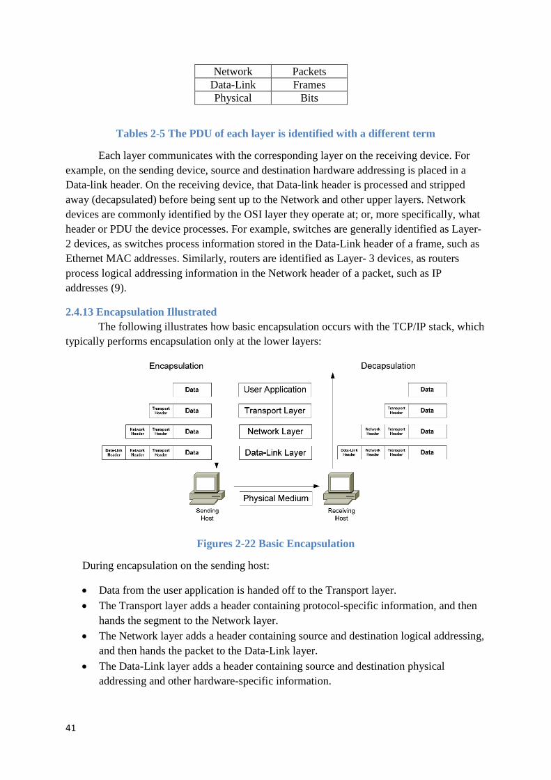
41
Network Packets Data-Link Frames Physical Bits
Tables 2-5 The PDU of each layer is identified with a different term
Each layer communicates with the corresponding layer on the receiving device. For example, on the sending device, source and destination hardware addressing is placed in a Data-link header. On the receiving device, that Data-link header is processed and stripped away (decapsulated) before being sent up to the Network and other upper layers. Network devices are commonly identified by the OSI layer they operate at; or, more specifically, what header or PDU the device processes. For example, switches are generally identified as Layer-2 devices, as switches process information stored in the Data-Link header of a frame, such as Ethernet MAC addresses. Similarly, routers are identified as Layer- 3 devices, as routers process logical addressing information in the Network header of a packet, such as IP addresses (9).
2.4.13 Encapsulation Illustrated The following illustrates how basic encapsulation occurs with the TCP/IP stack, which
typically performs encapsulation only at the lower layers:
Figures 2-22 Basic Encapsulation
During encapsulation on the sending host:
• Data from the user application is handed off to the Transport layer. • The Transport layer adds a header containing protocol-specific information, and then
hands the segment to the Network layer. • The Network layer adds a header containing source and destination logical addressing,
and then hands the packet to the Data-Link layer. • The Data-Link layer adds a header containing source and destination physical
addressing and other hardware-specific information.
42
• The Data-Link frame is then handed off to the Physical layer to be transmitted on the network medium as bits.
During decapsulation on the receiving host, the reverse occurs:
• The frame is received from the physical medium. • The Data-Link layer processes its header, strips it off, and then hands it off to the
Network layer. • The Network layer processes its header, strips it off, and then hands it off to the
Transport layer. • The Transport layer processes its header, strips it off, and then hands the data to the
user application. (OSI Reference Model v1.31 – Aaron Balchunas Oct 2007)
2.4.14 OSI Reference Model Example A web browser serves as a good practical illustration of the OSI model and the TCP/IP
protocol suite:
• The web browser serves as the user interface for accessing a website. The browser itself does not function at the Application layer. Instead, the web browser invokes the Hyper Text Transfer Protocol (HTTP) to interface with the remote web server, which is why http:// precedes every web address.
• The Internet can provide data in a wide variety of formats, a function of the Presentation layer. Common formats on the Internet include HTML, XML, PHP, GIF, and JPEG. Any encryption or compression mechanisms used on a website are also considered a Presentation layer function.
• The Session layer is responsible for establishing, maintaining, and terminating the session between devices, and determining whether the communication is half-duplex or full-duplex. However, the TCP/IP stack generally does not include session-layer protocols, and is reliant on lower-layer protocols to perform these functions.
• HTTP utilizes the TCP Transport layer protocol to ensure the reliable delivery of data. TCP establishes and maintains a connection from the client to the web server, and packages the higher-layer data into segments. A sequence number is assigned to each segment so that data can be reassembled upon arrival.
• The best path to route the data between the client and the web server is determined by IP, a Network layer protocol. IP is also responsible for the assigned logical addresses on the client and server, and for encapsulating segments into packets.
• Data cannot be sent directly to a logical address. As packets travel from network to network, IP addresses are translated to hardware addresses, which are a function of the Data-Link layer. The packets are encapsulated into frames to be placed onto the physical medium.
• The data is finally transferred onto the network medium at the Physical layer, in the form of raw bits. Signaling and encoding mechanisms are defined at this layer, as is the hardware that forms the physicalconnection between the client and the web server. (9)

43
2.4.15 IP and the DoD Model The Internet Protocol (IP) was originally developed by the Department of Defense
(DoD), and was a cornerstone for a group of protocols that became known as the TCP/IP protocol suite (9).
The DoD developed their own networking model, which became known as the DoD or TCP/IP Model. It consists of four layers:
7. Application 4. Application 6. Presentation
5. Session 4. Transport 3. Host-to-Host 3. Network 2. Internet 2. Data-link 1. Network
Access 1. Physical
Tables 2-6 Osi Model and DoD Model
The consolidated DoD model is generally regarded as more practical than the OSI model. Upper layer protocols often provide services that span the top three layers. A converged Data-link and Physical layer is also sensible, as many technologies provide specifications for both layers, such as Ethernet.
The following chart illustrates where common protocols fit into the DoD model:
Layer Example Protocols Application FTP, HTTP, SMTP Host-to-Host TCP, UDP
Internet IP Network Access Ethernet
Tables 2-7 Layer and Example Protocols
Despite the practicality of the DoD model, the OSI model is still the basis for most network terminology (9).
2.5 TCP/IP Architecture and the TCP/IP Model The OSI reference model consists of seven layers that represent a functional division
of the tasks required to implement a network. It is a conceptual tool that I often use to show how various protocols and technologies fit together to implement networks. However, it's not the only networking model that attempts to divide tasks into layers and components. The TCP/IP protocol suite was in fact created before the OSI Reference Model; as such, its inventors didn't use the OSI model to explain TCP/IP architecture (even though the OSI model is often used in TCP/IP discussions today, as you will see in this Guide, believe me.) (9)
2.5.1 The TCP/IP Model The developers of the TCP/IP protocol suite created their own architectural model to
help describe its components and functions. This model goes by different names, including
44
the TCP/IP model, the DARPA model (after the agency that was largely responsible for developing TCP/IP) and the DOD model (after the United States Department of Defense, the “D” in “DARPA”). I just call it the TCP/IP model since this seems the simplest designation for modern times (9).
Regardless of the model you use to represent the function of a network and regardless of what you call that model the functions that the model represents are pretty much the same. This means that the TCP/IP and the OSI models are really quite similar in nature even if they don't carve up the network functionality pie in precisely the same way. There is a fairly natural correspondence between the TCP/IP and OSI layers, it just isn't always a “one-to-one” relationship. Since the OSI model is used so widely, it is common to explain the TCP/IP architecture both in terms of the TCP/IP layers and the corresponding OSI layers, and that's what I will now do (9).
2.5.2 TCP/IP Model Layers The TCP/IP model uses four layers that logically span the equivalent of the top six
layers of the OSI reference model; this is shown in Figure 20. (The physical layer is not covered by the TCP/IP model because the data link layer is considered the point at which the interface occurs between the TCP/IP stack and the underlying networking hardware.) The following are the TCP/IP model layers, starting from the bottom (9).
The TCP/IP architectural model has four layers that approximately match six of the
seven layers in the OSI Reference Model. The TCP/IP model does not address the physical layer, which is where hardware devices reside. The next three layers network interface, internet and (host-to-host) transport correspond to layers 2, 3 and 4 of the OSI model. The TCP/IP application layer conceptually “blurs” the top three OSI layers. It’s also worth noting that some people consider certain aspects of the OSI session layer to be arguably part of the TCP/IP host-to-host transport layer (9).
2.5.3 Network Interface Layer As its name suggests, this layer represents the place where the actual TCP/IP protocols
running at higher layers interface to the local network. This layer is somewhat “controversial” in that some people don't even consider it a “legitimate” part of TCP/IP. This is usually because none of the core IP protocols run at this layer. Despite this, the network interface layer is part of the architecture. It is equivalent to the data link layer (layer two) in the OSI Reference Model and is also sometimes called the link layer. You may also see the name network access layer (9).
On many TCP/IP networks, there is no TCP/IP protocol running at all on this layer, because it is simply not needed. For example, if you run TCP/IP over an Ethernet, then Ethernet handles layer two (and layer one) functions. However, the TCP/IP standards do define protocols for TCP/IP networks that do not have their own layer two implementation. These protocols, the Serial Line Internet Protocol (SLIP) and the Point-to-Point Protocol (PPP), serve to fill the gap between the network layer and the physical layer. They are commonly used to facilitate TCP/IP over direct serial line connections (such as dial-up telephone networking) and other technologies that operate directly at the physical layer (9).

45
2.5.4 Internet Layer This layer corresponds to the network layer in the OSI Reference Model (and for that
reason is sometimes called the network layer even in TCP/IP model discussions). It is responsible for typical layer three jobs, such as logical device addressing, data packaging, manipulation and delivery, and last but not least, routing. At this layer we find the Internet Protocol (IP), arguably the heart of TCP/IP, as well as support protocols such as ICMP and the routing protocols (RIP, OSFP, BGP, etc.) The new version of IP, called IP version 6, will be used for the Internet of the future and is of course also at this layer (9).
2.5.5 (Host-to-Host) Transport Layer This primary job of this layer is to facilitate end-to-end communication over an
internetwork. It is in charge of allowing logical connections to be made between devices to allow data to be sent either unreliably (with no guarantee that it gets there) or reliably (where the protocol keeps track of the data sent and received to make sure it arrives, and re-sends it if necessary). It is also here that identification of the specific source and destination application process is accomplished (9).
The formal name of this layer is often shortened to just the transport layer; the key TCP/IP protocols at this layer are the Transmission Control Protocol (TCP) and User Datagram Protocol (UDP). The TCP/IP transport layer corresponds to the layer of the same name in the OSI model (layer four) but includes certain elements that are arguably part of the OSI session layer. For example, TCP establishes a connection that can persist for a long period of time, which some people say makes a TCP connection more like a session (9).
2.5.6 Application Layer This is the highest layer in the TCP/IP model. It is a rather broad layer, encompassing
layers five through seven in the OSI model. While this seems to represent a loss of detail compared to the OSI model, I think this is probably a good thing! The TCP/IP model better reflects the “blurry” nature of the divisions between the functions of the higher layers in the OSI model, which in practical terms often seem rather arbitrary. It really is hard to separate some protocols in terms of which of layers five, six or seven they encompass. (I didn't even bother to try in this Guide which is why the higher-level protocols are all in the same chapter, while layers one through four have their protocols listed separately.) (9) Numerous protocols reside at the application layer. These include application protocols such as HTTP, FTP and SMTP for providing end-user services, as well as administrative protocols like SNMP, DHCP and DNS (9). The internet and host-to-host transport layers are usually considered the “core” of TCP/IP architecture, since they contain most of the key protocols that implement TCP/IP internetworks (9). In the topic that follows I provide a brief look at each of the TCP/IP protocols covered in detail in this Guide and more detail on where they all fit into the TCP/IP architecture. There I will also cover a couple of protocols that don't really fit into the TCP/IP layer model at all (9). The architecture of the TCP/IP protocol suite is often described in terms of a layered reference model called the TCP/IP model, DARPA model or DOD model. The TCP/IP model includes

46
four layers: the network interface layer (responsible for interfacing the suite to the physical hardware on which it runs), the internet layer (where device addressing, basic datagram communication and routing take place), the host-to-host transport layer (where connections are managed and reliable communication is ensured) and the application layer (where end-user applications and services reside.) The first three layers correspond to layers two through four of the OSI Reference Model respectively; the application layer is equivalent to OSI layers five to seven (9).
2.5.7 What is IPv4? IPv4 was the first version of Internet Protocol to be widely used, and accounts for
most of today’s Internet traffic. There are just over 4 billion IPv4 addresses. While that is a lot of IP addresses, it isnot enough to last forever.
2.5.8 What is IPv6? IPv6 is a newer numbering system that provides a much larger address pool than IPv4.
It was deployed in 1999 and should meet the world’s IP addressing needs well into the future.
2.5.9 What is the major difference? The major difference between IPv4 and IPv6 is the number of IP addresses. There are
4,294,967,296 IPv4 addresses. In contrast, there are 340,282,366,920,938,463,463,374, 607,431,768,211,456 IPv6 addresses. The technical functioning of the Internet remains the same with both versions and it is likely that both versions will continue to operate simultaneously on networks well into the future. To date, most networks that use IPv6 support both IPv4 and IPv6 addresses in their networks.
Internet Protocol Version 4
(Ipv4) Internet Protocol Version 6 (Ipv6)
Deployed 1981 1999
Address Size 32-bit number 128-bit number
Address Format Dotted Decimal Notation: 192.149.252.76
Hexadecimal Notation: 3FFE:F200:0234:AB00: 0123:4567:8901:ABCD
Prefix Notation 192.149.0.0/24 3FFE:F200:0234::/48
Number of Addresses 32 2 = ~4,294,967,296
128 2 = ~340,282,366, 920,938,463,463,374, 607,431,768,211,456
Tables 2-8 Ipv4 and Ipv6 between difference

47
3 IP PBX PHONE SYSTEM An IP-PBX is a complete telephony system that provides telephone calls over IP data
networks. All conversations are transmitted as data packets over the network. The technology includes advanced communication features but also provides for significant worry-free scalability and robustness that all enterprises seek. An enterprise does not need to disrupt its current external communication infrastructure: An IP-PBX is able to connect to traditional PSTN lines via a VoIP gateway so an enterprise can keep its regular telephone system (10).
With an IP-PBX solution, the business owns and operates the equipment so an upfront capital investment is required to purchase the equipment and then there are on-going maintenance costs. This is often better for larger businesses as the call control remains internal to the corporate network and a single wire can be routed to an office to provide both data and voice communications (10).
3.1 Voip The term Voice over Internet Protocol, or VoIP, has been used as a catch-all phrase in
the industry to refer collectively to a large group of Technologies designed to provide Internet-based communications services. More accurately, VoIP refers only to the underlying transport protocol that encapsulates voice traffic or voice media streams and allows them to be carried over data networks, using IP network technologies or internet protocols. VoIP, however, is not IP Telephony, nor is it the more widely used industry terminology called IP Communications that refers to an even broader definition of communications networking applications and technologies. VoIP can be understood as simply a transport protocol for carrying voice over any packet network, usually between sites. The term convergence, also sometimes referred as a multi-service network, refers to the integration of data, voice, and video solutions onto a converged network infrastructure (10). PSTN stands for Public Switched Telephone Network. It is the same thing as POTS (Plain Old Telephone System). It is simply the worldwide telephone network. It carries analog data. In constrast, VoIP uses digital data.
3.1.1 H323 H323 is a set of standards from the ITU-T, which defines a set of protocols to provide
audio and visual communication over a computer network (11).
H323 is a relatively old protocol and is currently being superceded by SIP – Session Initiation Protocol. One of the advantages of SIP is that its much less complex and resembles the HTTP / SMTP protocols (11).
Therefore most VOIP equipment available today follows the SIP standard. Older VOIP equipment though would follow H 323 (11).
3.1.2 Sip SIP (Session Initiation Protocol) is a signaling protocol used to create, manage and
terminate sessions in an IP based network. A session could be a simple two-way telephone call or it could be a collaborative multi-media conference session. This makes possible to implement services like voice-enriched e-commerce, web page click-to-dial or Instant

48
Messaging with buddy lists in an IP based environment (11). H323 is used instead because it's new.
3.2 IP Telephony IP Telephony provides the benefits of advanced dial tone and enterprise class
telephony features and capabilities, improved support for mobility and call processing services over a converged packet network. IP Telephony thereby eliminates the need, cost, andexpense of running separate voice and data networks. Because IP Telephony is more flexible, open, and adaptive than legacy voice environments, it also reduces expense, provides for better and more productive applications, and improves an organization's ability to extend capabilities on its' network. IP Telephony also supports voice in addition to data applications that can be delivered to the IP phone or softphone from web services, backend / front end databases, or office systems. IP phone service applications include enterprise directories, emergency alerting, Amber Alerts, support for N11 servic- es, kiosk applications, and custom applications. IP Telephony allows organizations to reuse their existing network infrastructure. With IP Telephony, employees can use IP hand sets or softphones any where on the corporate network. Generally only a single Ethernet port is required to provide both desktop and IP Telephony (voice) services. Power over Ethernet using the 802.3af standard or prestandards based power can be used with great advantage throughout an IP Telephony environment to power other network appliances such as 802.11a/b/g wireless access points, IP video surveillance cameras and IP phones. IP Telephony systems also provide the advantage of lower cost moves/adds/changes administration allowing employees and departments to more easily move from location to location withoutthe burdens of administration and service interruption (10). (See Figure 3.23)
Figures 3-1 Three Different IP Phone Configurations
Because IP Telephony works with packet networks, the model of support used for IP
Telephony can be the same as the one used for the desktop, therebyreducing and simplifying staffing requirements. Since the IP phone or softphone is an intelligent endpointon the network, it has the intelligence to seek out communications services from one or many

49
IPTelephony call processing services. In addition, clustering and high availability networking technologies provide for a much more business resilient environment at a far lower overall cost (10). As mentioned above, IP Telephony can be used to: 1) supplement; 2) extend; or 3) replace existing voice services that are provided by legacy voice technologies.
Applications of IP Telephony include connecting it toan existing PBX environment and using IP Telephony and its applications to support mobile workers and telecommuting applications with a combination of softphone and VPN services. Because workers can be more flexible and IP Telephony can support extension mobility (hotdesk) applications, enterprises and organizations can save real estate costs while increasing the productivity of their workforce. Typically, productivity can be increased from 10 percent to 20 percent while increased flexibility and reduced costs from IP Telephony can account for an additional 15 percent to 20 percent of cost savings. In some cases, the cost savings are very high. This is true in Greenfield sites (new sites), where the single IP telephony cabling infrastructure, single network infrastructure, and one set of common operations are required to support data, voice, and video services (10).
Most organizations plan their migration to IP Telephony based on key events or needs to evolve their infrastructure to IP Communication over time. Typical requirements for an IP Telephony solution are the converged network components consisting of switches and routers that provide for quality of service (QoS), security, in-line power, and virtual local area networks to provide control and separation of voice, video and data traffic, as well as wireless traffic. In addition, management tools and protocols that support the ability to ensure multi service networking traffic such as real time and streaming video can also be supported and accommodated with appropriate QoS tools. The ability to support a robust set of gateway technologies to enable connections to any broadband technology, or PSTN technology, (voice interface cards and WAN interface cards) and support for protocols that handle multicast, and/or network content distribution, caching and filtering (for video on demand, etc.), as well as secure wireless technologies, are other consideratio ns for evaluation of the converged network infrastructure (10).
3.3 What is Asterisk? Asterisk is an open source framework for building communications applications.
Asterisk turns an ordinary computer into a communications server. Asterisk powers IP PBX systems, VoIP gateways, conference servers and more. It is used by small businesses, large businesses, call centers, carriers and governments worldwide. Asterisk is free and open source. Asterisk is sponsored by Digium, the Asterisk Company. Asterisk is “ under the hood” in countless voice communications applications and is capable of interfacing with many traditional Telcom protocols, VoIP protocols, and codecs. Asterisk provides a staggering list of capabilities and features including (12): IVR ACD Audio and Video Conferencing Voicemail Call Recording Fax termination CDR

50
3.3.1 Installing AsteriskNOW
Thank you for downloading AsteriskNOW. This Linux distribution has been carefully customized and tested with Asterisk, and installs all of the packages needed for its use. It is the officially recommended development and runtime platform for Asterisk and Digium hardware, including Digium phones. (12)
This guide provides a brief overview of installation, configuration, and maintenance of your system (12).
More information is available at http://wiki.centos.org/.
Please report any bugs at https://issues.asterisk.org/jira
3.3.1.1 Installation
Burn the AsteriskNOW DVD image to DVD disc and then boot from the DVD to begin the installation process.
If you are unfamiliar with burning disc images, the Ubuntu community has a great Burning ISO Howto available at https://help.ubuntu.com/community/BurningIsoHowto.
If you are unfamiliar with booting to DVD, the Ubuntu community has a wonderful Boot From DVD HOWTO available at https://help.ubuntu.com/community/BootFromCD.
After booting from the AsteriskNOW DVD, you will be presented with the following screen and options for an installation with, or without the FreePBX web interface. This QuickStart assumes that the FreePBX web interface has been installed. To do this, selection option 1 and press <ENTER>:
Figures 3-1

51
This will begin the automated graphical installation process (12). During the installation, you are first presented with an option for setting the system time zone:
Figures 3-2
Choose the location that is nearest to you and move to the next screen. Next, you will be prompted to set a root password:
Figures 3-3
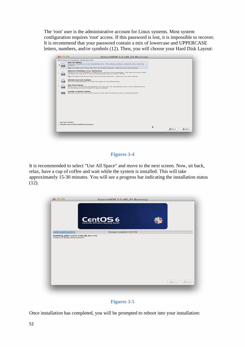
52
The 'root' user is the administrative account for Linux systems. Most system configuration requires 'root' access. If this password is lost, it is impossible to recover. It is recommend that your password contain a mix of lowercase and UPPERCASE letters, numbers, and/or symbols (12). Then, you will choose your Hard Disk Layout:
Figures 3-4
It is recommended to select "Use All Space" and move to the next screen. Now, sit back, relax, have a cup of coffee and wait while the system is installed. This will take approximately 15-30 minutes. You will see a progress bar indicating the installation status (12).
Figures 3-5
Once installation has completed, you will be prompted to reboot into your installation:

53
Figures 3-6
After the system reboots you will see this screen:
Figures 3-7
Congratulations! You have successfully installed AsteriskNOW. Notice the text that says "To configure AsteriskNOW with FreePBX, point your web browser to http://xx.xx.xx.xx/." Write this down, you will need it in the next section.
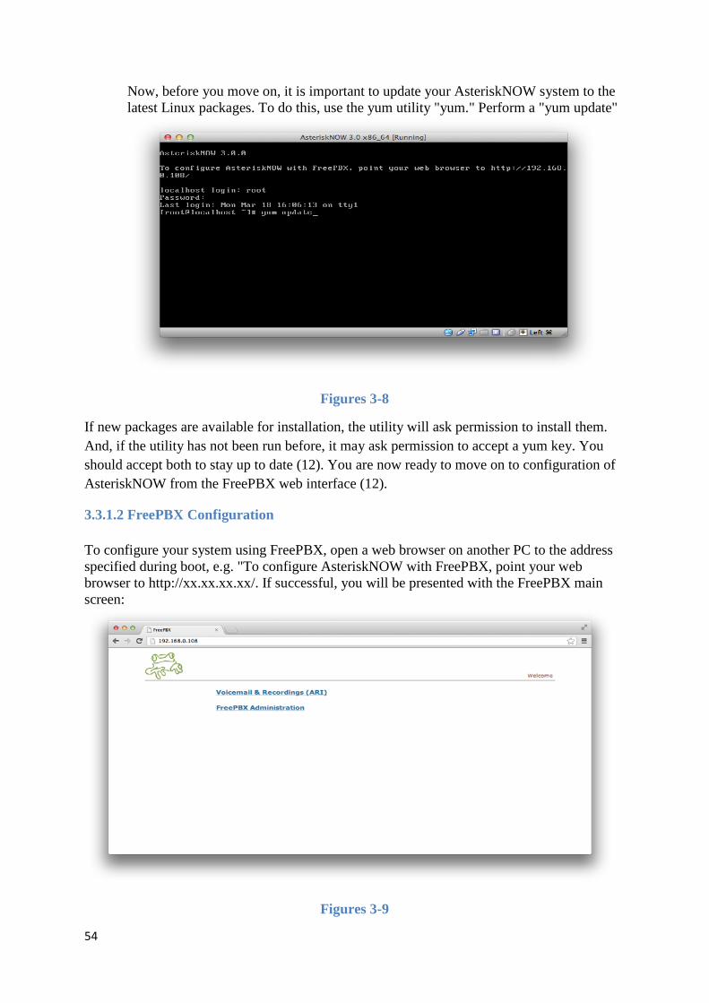
54
Now, before you move on, it is important to update your AsteriskNOW system to the latest Linux packages. To do this, use the yum utility "yum." Perform a "yum update"
Figures 3-8
If new packages are available for installation, the utility will ask permission to install them. And, if the utility has not been run before, it may ask permission to accept a yum key. You should accept both to stay up to date (12). You are now ready to move on to configuration of AsteriskNOW from the FreePBX web interface (12).
3.3.1.2 FreePBX Configuration
To configure your system using FreePBX, open a web browser on another PC to the address specified during boot, e.g. "To configure AsteriskNOW with FreePBX, point your web browser to http://xx.xx.xx.xx/. If successful, you will be presented with the FreePBX main screen:
Figures 3-9

55
From here, we want the "FreePBX Administration" link. Click it, and you will see the FreePBX login screen:
Figures 3-10
The default username is admin The default password is admin
Having successfully logged into FreePBX, you will see the FreePBX dashboard:
Figures 3-11

56
Notice the Red reload button. It will appear after changes are made to any page. If you see it, it should be clicked, it will affect any changes on the system that FreePBX needs to make. This guide assumes that whenever you see it, you will click it (12).
Next, we will change the default admin password. This is imperative! Failure to do this is inviting disaster. The importance of doing this CANNOT be understated.
First, visit the Admin tool
Figures 3-12
Next, select admin from the right column
Figures 3-13

57
Then, change the admin password
Figures 3-14
Finally, one should update any out of date modules on the system. To do this, we will visit the Module Admin tool:
Figures 3-15

58
Click the Check Online button and you will see any out of date modules
Figures 3-16
To update a module, click it, and then select the Download option
Figures 3-17
Finally, press the Process button and follow the instructions to complete the module update (12).

59
REFERENCES 1. Öztürk, Atilla. Mobil telekominikasyon lisans rejimi: Dünya örnekleri ve Türkiye analizi Uzmanlık tezi . Nisan 2002.
2. Mert, Volkan. İnternetin pazarlama açısından önemi Bitirme tezi. Mart 2000.
3. Opplige, Rolf. Security Technologies for the World Wide Web. s.l. : Artech House Publishers, 2002.
4. Alkım, Barış. IPv4 ve IPv6. s.l. : Chip Magazine, Mayıs 2007 .
5. A History of Mass Communication Six Information Revolutions. Fang, Irving. s.l. : Boston, Oxford, Johannesburg, Melbourne, New Delhi, Singapore, 1997 .
6. Computer Networks Professional Aim thesis. 1001, COMP. s.l. : Carleton University , 2007/2008.
7. CAMI Research Inc. E. Strangio, Christopher. 1993-2012.
8. Cisco Network Topologies and LAN Design . Nov 16 2001.
9. Balchunas, Aaron. OSI Reference Model. Oct 2007.
10. NASCIO. VoIP and IP Telephony:. May 2005.
11. M.Handley, E.Schooler. Session Invitation Protocol (SIP). February 1996.
12. Digium. The Asterisk. 2012 .


