PROUDLY MADE IN THE USA C e r tifi e d C o m p a n y ISO 9001:2008 IP100/200 Series Adjustable Depth Insertion Paddlewheel Instructions IP11x/21x (Shown with externally powered electronics) IP15x/25x (Shown with battery powered electronics)
Transcript
PROUDLY MADE IN THE
USA
Ce
rtified Company
ISO9001:2008
IP100/200 Series Adjustable Depth Insertion
Paddlewheel Instructions
IP11x/21x(Shown with externally powered electronics) IP15x/25x
(Shown with battery powered electronics)
IP100/200 SERIES INSTRUCTIONS
Seametrics • 253.872.0284 Page 2 seametrics.com
TABLE OF CONTENTS
General Information General Information ...................................................................................................................................................Page 3Features ...........................................................................................................................................................................Page 3Specifications ................................................................................................................................................................Page 5
Operation and MaintenanceOperation Theory ........................................................................................................................................................Page 13Flow Rate ........................................................................................................................................................................Page 13Calibration (K-Factor) .................................................................................................................................................Page 13Rotor Replacement .....................................................................................................................................................Page 13Checking Signal ............................................................................................................................................................Page 13Parts Explosion .............................................................................................................................................................Page 14Parts List ..........................................................................................................................................................................Page 14
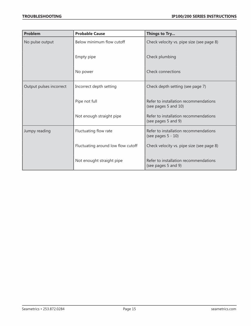
TroubleshootingProblem ...........................................................................................................................................................................Page 15Probable Cause .............................................................................................................................................................Page 15Things To Try..................................................................................................................................................................Page 15
IP100/200 SERIES INSTRUCTIONS
Seametrics • 253.872.0284 Page 3 seametrics.com
GENERAL INFORMATION
Features
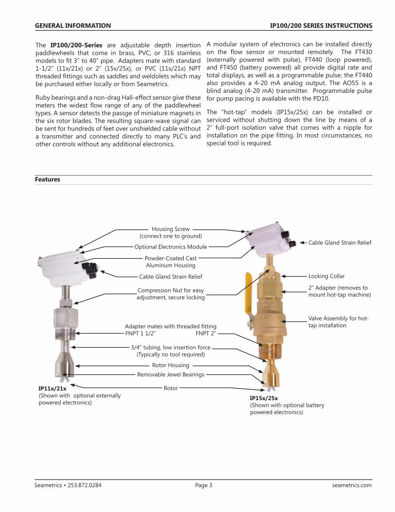
The IP100/200-Series are adjustable depth insertion paddlewheels that come in brass, PVC, or 316 stainless models to fit 3” to 40” pipe. Adapters mate with standard 1-1/2” (11x/21x) or 2” (15x/25x), or PVC (11x/21x) NPT threaded fittings such as saddles and weldolets which may be purchased either locally or from Seametrics.
Ruby bearings and a non-drag Hall-effect sensor give these meters the widest flow range of any of the paddlewheel types. A sensor detects the passge of miniature magnets in the six rotor blades. The resulting square-wave signal can be sent for hundreds of feet over unshielded cable without a transmitter and connected directly to many PLC’s and other controls without any additional electronics.
A modular system of electronics can be installed directly on the flow sensor or mounted remotely. The FT430 (externally powered with pulse), FT440 (loop powered), and FT450 (battery powered) all provide digital rate and total displays, as well as a programmable pulse; the FT440 also provides a 4-20 mA analog output. The AO55 is a blind analog (4-20 mA) transmitter. Programmable pulse for pump pacing is available with the PD10.
The “hot-tap” models (IP15x/25x) can be installed or serviced without shutting down the line by means of a 2” full-port isolation valve that comes with a nipple for installation on the pipe fitting. In most circumstances, no special tool is required.
Optional Electronics Module
Powder-Coated Cast Aluminum Housing
Rotor Housing
3/4” tubing, low insertion force (Typically no tool required)
Adapter mates with threaded fittingFNPT 1 1/2” FNPT 2”
Compression Nut for easy adjustment, secure locking
Cable Gland Strain Relief
Rotor
Housing Screw (connect one to ground)
Cable Gland Strain Relief
Valve Assembly for hot-tap installation
2” Adapter (removes to mount hot-tap machine)
Removable Jewel Bearings
Locking Collar
IP11x/21x(Shown with optional externally powered electronics)
IP15x/25x(Shown with optional battery powered electronics)
IP100/200 SERIES INSTRUCTIONS
Seametrics • 253.872.0284 Page 4 seametrics.com
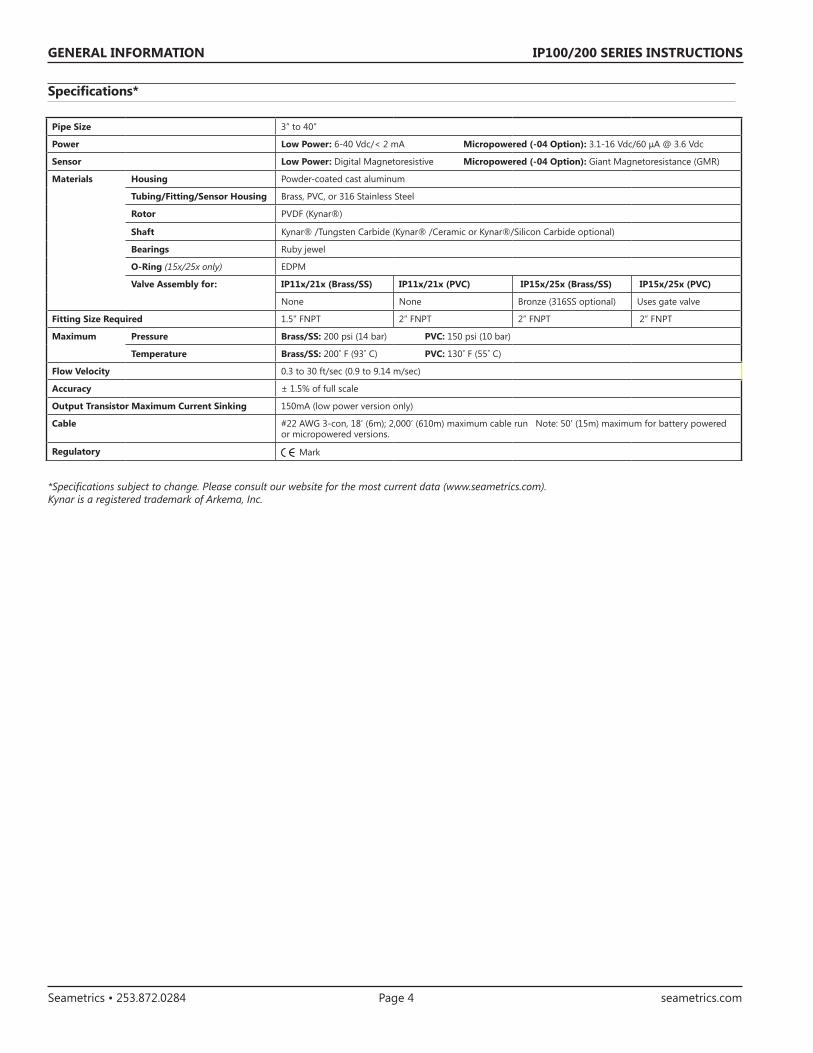
Specifications*
GENERAL INFORMATION
*Specifications subject to change. Please consult our website for the most current data (www.seametrics.com).Kynar is a registered trademark of Arkema, Inc.
Pipe Size 3” to 40”
Power Low Power: 6-40 Vdc/< 2 mA Micropowered (-04 Option): 3.1-16 Vdc/60 μA @ 3.6 Vdc
Temperature Brass/SS: 200˚ F (93˚ C) PVC: 130˚ F (55˚ C)
Flow Velocity 0.3 to 30 ft/sec (0.9 to 9.14 m/sec)
Accuracy ± 1.5% of full scale
Output Transistor Maximum Current Sinking 150mA (low power version only)
Cable #22 AWG 3-con, 18’ (6m); 2,000’ (610m) maximum cable run Note: 50’ (15m) maximum for battery powered or micropowered versions.
Regulatory Mark
IP100/200 SERIES INSTRUCTIONS
Seametrics • 253.872.0284 Page 5 seametrics.com
INSTALLATION
Positioning the Meter
For best results, the IP sensor should be installed with at least ten diameters of straight pipe upstream and five downstream. Certain extreme situations such as partially-opened valves are particularly difficult and may require fifteen diameters upstream. (See Straight Pipe Recommendations.)
Distorted Flows
Horizontal (3 o’clock or 9 o’clock position) is the preferred installation orientation, since it improves low-flow performance and avoids problems with trapped air and sediment. (See Orienting the Meter diagram below.) Bottom (6 o’clock), top (12 o’clock), and vertical pipe installations are all acceptable if required by the piping layout.
Orienting the Meter
FLOW
Faster FlowCauses MeterTo Read High
10X 5X
DistortedFlow Profile
Fair Unacceptable if pipe contains air
BestPosition
Fair Unacceptable if pipe contains sediment
Caution: These flow sensors are not recommended for installation downstream of a boiler feedwater pump where installation fault may
expose the flow sensor to boiler pressure and temperature. Maximum recommended temperature is 200°F.
Immersion
The IP100/200 Series standard sensors are not designed for continuous underwater operation. If this is a possibility, as in a flooded vault, a unit modified for immersion should be specified (Option -40).
IP100/200 SERIES INSTRUCTIONS
Seametrics • 253.872.0284 Page 6 seametrics.com
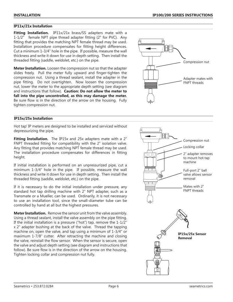
Fitting Installation. IP11x/21x brass/SS adapters mate with a 1-1/2” female NPT pipe thread adapter fitting (2" for PVC). Any fitting that provides the matching NPT female thread may be used. Installation procedure compensates for fitting height differences. Cut a minimum 1-3/4” hole in the pipe. If possible, measure the wall thickness and write it down for use in depth setting. Then install the threaded fitting (saddle, weldolet, etc.) on the pipe.
Meter Installation. Loosen the compression nut so that the adapter slides freely. Pull the meter fully upward and finger-tighten the compression nut. Using a thread sealant, install the adapter in the pipe fitting. Do not overtighten. Now loosen the compression nut, lower the meter to the appropriate depth setting (see diagram and instructions that follow). Caution: Do not allow the meter to fall into the pipe uncontrolled, as this may damage the meter. Be sure flow is in the direction of the arrow on the housing. Fully tighten compression nut.
Hot tap’ IP meters are designed to be installed and serviced without depressurizing the pipe.
Fitting Installation. The IP15x and 25x adapters mate with a 2” FNPT threaded fitting for compatibility with the 2” isolation valve. Any fitting that provides matching NPT female thread may be used. The installation procedure compensates for differences in fitting height.
If initial installation is performed on an unpressurized pipe, cut a minimum 1-3/4” hole in the pipe. If possible, measure the wall thickness and write it down for use in depth setting. Then install the threaded fitting (saddle, weldolet, etc.) on the pipe.
If it is necessary to do the initial installation under pressure, any standard hot tap drilling machine with 2” NPT adapter, such as a Transmate or a Mueller, can be used. Ordinarily, it is not necessary to use an installation tool, since the small-diameter tube can be controlled by hand at all but the highest pressures.
Meter Installation. Remove the sensor unit from the valve assembly. Using a thread sealant, install the valve assembly on the pipe fitting. If the initial installation is a pressure (“hot”) tap, remove the 1-1/2” x 2” adapter bushing at the back of the valve. Thread the tapping machine on, open the valve, and tap using a minimum of 1-3/4” or maximum 1-7/8” cutter. After retracting the machine and closing the valve, reinstall the flow sensor. When the sensor is secure, open the valve and adjust depth setting (see diagram and instructions that follow). Be sure flow is in the direction of the arrow on the housing. Tighten locking collar and compression nut fully.
Compression nut
Adapter mates with FNPT threads
Compression nut
2” adapter removes to mount hot-tap machine
Full-port 2” ball valve allows sensor removal
Mates with 2” FNPT threads
IP15x/25x Sensor Removal
Locking collar
INSTALLATION
IP11x/21x Installation
IP15x/25x Installation
IP100/200 SERIES INSTRUCTIONS
Seametrics • 253.872.0284 Page 7 seametrics.com
INSTALLATION
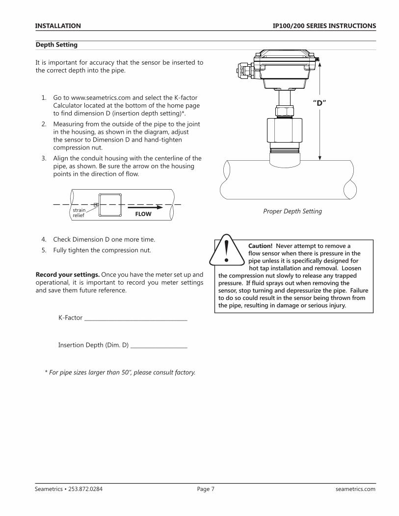
“D”
It is important for accuracy that the sensor be inserted to the correct depth into the pipe.
1. Go to www.seametrics.com and select the K-factor Calculator located at the bottom of the home page to find dimension D (insertion depth setting)*.
2. Measuring from the outside of the pipe to the joint in the housing, as shown in the diagram, adjust the sensor to Dimension D and hand-tighten compression nut.
3. Align the conduit housing with the centerline of the pipe, as shown. Be sure the arrow on the housing points in the direction of flow.
4. Check Dimension D one more time.
5. Fully tighten the compression nut.
Record your settings. Once you have the meter set up and operational, it is important to record you meter settings and save them future reference.
K-Factor ______________________________________
Insertion Depth (Dim. D) _____________________
* For pipe sizes larger than 50”, please consult factory.
strain relief FLOW
Caution! Never attempt to remove a flow sensor when there is pressure in the pipe unless it is specifically designed for hot tap installation and removal. Loosen
the compression nut slowly to release any trapped pressure. If fluid sprays out when removing the sensor, stop turning and depressurize the pipe. Failure to do so could result in the sensor being thrown from the pipe, resulting in damage or serious injury.
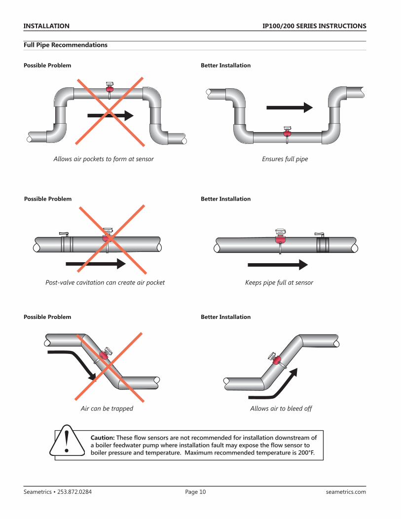
Caution: These flow sensors are not recommended for installation downstream of a boiler feedwater pump where installation fault may expose the flow sensor to boiler pressure and temperature. Maximum recommended temperature is 200°F.
Full Pipe Recommendations
Better InstallationPossible Problem
Air can be trapped Allows air to bleed off
Better InstallationPossible Problem
Allows air pockets to form at sensor Ensures full pipe
Post-valve cavitation can create air pocket Keeps pipe full at sensor
Better InstallationPossible Problem
IP100/200 SERIES INSTRUCTIONS
Seametrics • 253.872.0284 Page 11 seametrics.com
CONNECTIONS
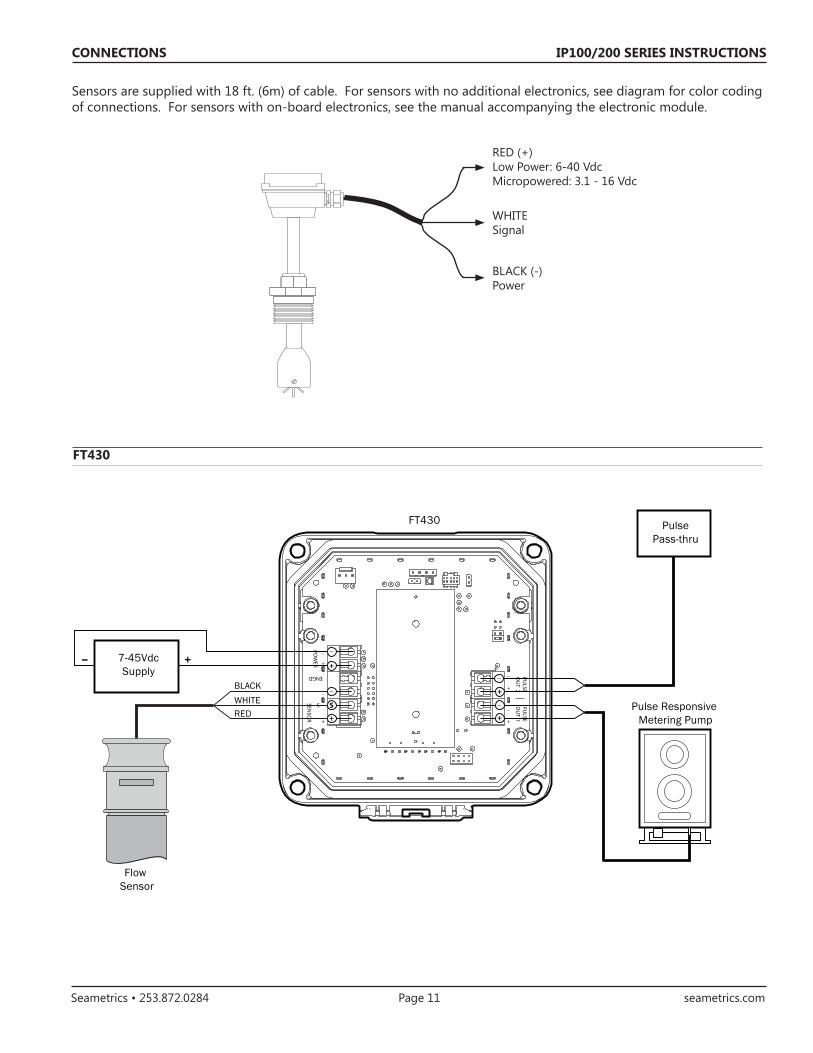
Sensors are supplied with 18 ft. (6m) of cable. For sensors with no additional electronics, see diagram for color coding of connections. For sensors with on-board electronics, see the manual accompanying the electronic module.
RED (+)Low Power: 6-40 VdcMicropowered: 3.1 - 16 Vdc
WHITESignal
BLACK (-)Power
RED (+) 6-24 Vdc
WHITE (signal)
BLACK (-) Power18' cable standard
POW
ERSEN
SOR
ENGD
+
_
_
+
S
PULSE
OU
T 2PU
LSEO
UT 1
+
_
+
_REDWHITEBLACK
+_ 7-45VdcSupply
Flow Sensor
FT430 Pulse Pass-thru
Pulse Responsive Metering Pump
_
+
S
_
+_
+_
+
FT430
IP100/200 SERIES INSTRUCTIONS
Seametrics • 253.872.0284 Page 12 seametrics.com
CONNECTIONS
FT440
POW
ERSEN
SOR
ENGD
+
_
_
+
S
PULSE
OU
T 2PU
LSEO
UT 1
+
_
+
_REDWHITEBLACK
+_ 9-30 VdcLoop Power
Supply
Flow Sensor
FT440
Electronic Metering Pumps
_
+
S
_
+_
+_
+
4-20mADevice
+_
FT450PO
WER
SENSO
R
ENGD
+
_
_
+
S
PULSE
OU
T 2PU
LSEO
UT 1
+
_
+
_REDWHITEBLACK
MicropowerFlow Sensor
FT450 Pulse Pass-thru
Pulse Responsive Metering Pump
Current Sinking Polarity-Sensitive
Lithium C, 3Vdc
ReplaceableBattery
_
+
S
_
+
_
+
IP100/200 SERIES INSTRUCTIONS
Seametrics • 253.872.0284 Page 13 seametrics.com
OPERATION AND MAINTANENCE
Operation Theory
In principle, an insertion flow sensor measures the velocity of flow at one point in the pipe, and flow rate and total can be inferred from this one point. Accuracy is decreased by any factor which makes the flow at the measured point unrepresentative of the entire flow stream. This includes distorted flow patterns caused by upstream fittings too close to the sensor. The worst offenders are fittings that increase the flow on one side of the pipe, such as partially-opened gate or butterfly valves. Fluid moving in a pipe does not all flow at the same velocity. Toward the center of the pipe, fluid moves faster than at the wall, and the relationship between the two changes as overall flow rate increases. This change in the “velocity profile” can result in non-linearity, which means that the K-factor that is correct for one flow rate may be incorrect for another. The recommended depth settings have been carefully chosen to minimize this source of error, and should be followed carefully, especially in the smaller pipe sizes.
Flow Rate
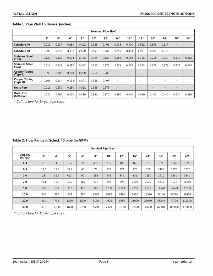
These sensors are designed to operate at flow velocities of 0.3 to 30 feet per second. (See chart for conversion to gallons per minute.) If erratic readings are encountered at low flows, check the chart to see if flow is below minimum for the pipe size. The standard shaft and bearings should have a long life at continuous high flow.
Calibration (“K-Factor”)
In order to properly process pulses from the flow sensor, a number must be entered into the control to which the sensor is connected. This number, called the K-factor, is the number of pulses the sensor puts out per unit of fluid passing through the pipe. It is normally provided for Seametrics sensors in pulses per gallon, and is given on the chart “K-factors for Various Pipe Sizes.” These numbers are based on extensive testing, which has shown close agreement between different IP sensors in the same installation. Typically, most K-factor error can be attributed to installation variables, such as depth setting and fitting configuration.
It is occasionally possible to field calibrate a sensor by catching the fluid in a measured container and comparing with the number of pulses recorded. (To record individual pulses, set the K-factor on the control to 1.00.) This is especially desirable if the installation has less than the recommended length of straight pipe upstream of the sensor.
Rotor Replacement
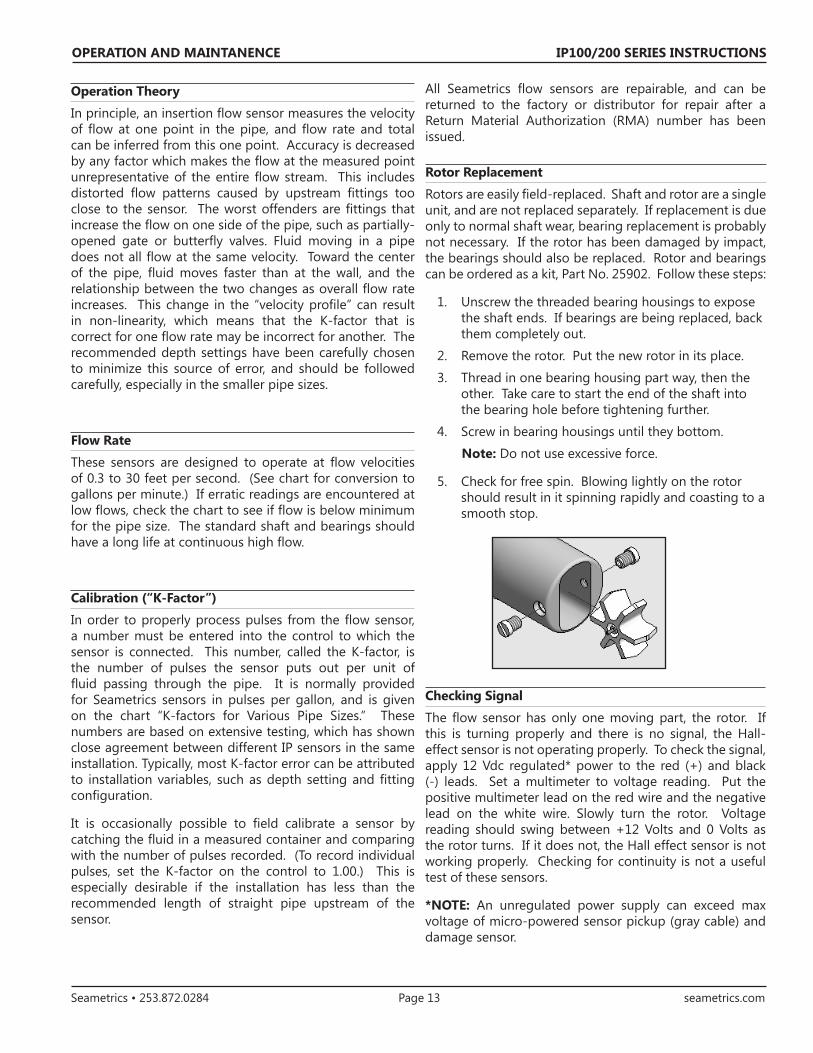
Rotors are easily field-replaced. Shaft and rotor are a single unit, and are not replaced separately. If replacement is due only to normal shaft wear, bearing replacement is probably not necessary. If the rotor has been damaged by impact, the bearings should also be replaced. Rotor and bearings can be ordered as a kit, Part No. 25902. Follow these steps:
1. Unscrew the threaded bearing housings to expose the shaft ends. If bearings are being replaced, back them completely out.
2. Remove the rotor. Put the new rotor in its place.
3. Thread in one bearing housing part way, then the other. Take care to start the end of the shaft into the bearing hole before tightening further.
4. Screw in bearing housings until they bottom.
Note: Do not use excessive force.
5. Check for free spin. Blowing lightly on the rotor should result in it spinning rapidly and coasting to a smooth stop.
All Seametrics flow sensors are repairable, and can be returned to the factory or distributor for repair after a Return Material Authorization (RMA) number has been issued.
Checking Signal
The flow sensor has only one moving part, the rotor. If this is turning properly and there is no signal, the Hall-effect sensor is not operating properly. To check the signal, apply 12 Vdc regulated* power to the red (+) and black (-) leads. Set a multimeter to voltage reading. Put the positive multimeter lead on the red wire and the negative lead on the white wire. Slowly turn the rotor. Voltage reading should swing between +12 Volts and 0 Volts as the rotor turns. If it does not, the Hall effect sensor is not working properly. Checking for continuity is not a useful test of these sensors.
*NOTE: An unregulated power supply can exceed max voltage of micro-powered sensor pickup (gray cable) and damage sensor.
IP100/200 SERIES INSTRUCTIONS
Seametrics • 253.872.0284 Page 14 seametrics.com
OPERATION AND MAINTANENCE
IP 11x/21x Parts
White Housing1a thru 7a
Blue Housing1b thru 7b
1 Upper housing/electronics
Contact service representative for your specific model
Contact service representative for your specific model