+ All Categories
Home > Documents > IP150+ Internet Module - ALARMAX.cz

IP150+ Internet Module - ALARMAX.cz

Date post: 19-Mar-2022
Category:
Upload: others
View: 5 times
Download: 0 times
Share this document with a friend
2
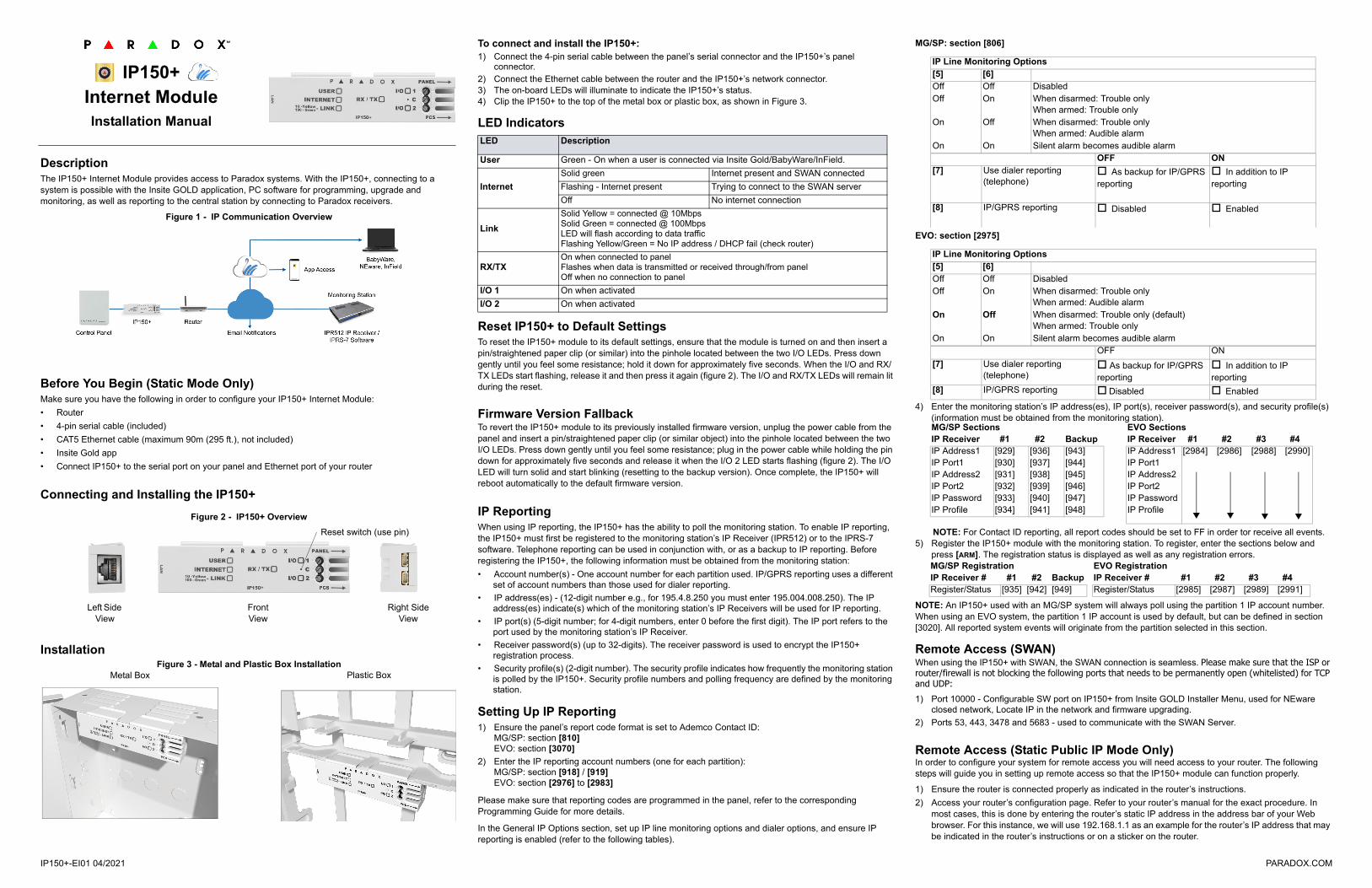
IP150+-EI01 04/2021 PARADOX.COM Description The IP150+ Internet Module provides access to Paradox systems. With the IP150+, connecting to a system is possible with the Insite GOLD application, PC software for programming, upgrade and monitoring, as well as reporting to the central station by connecting to Paradox receivers. Figure 1 - IP Communication Overview Before You Begin (Static Mode Only) Make sure you have the following in order to configure your IP150+ Internet Module: Router 4-pin serial cable (included) CAT5 Ethernet cable (maximum 90m (295 ft.), not included) Insite Gold app Connect IP150+ to the serial port on your panel and Ethernet port of your router Connecting and Installing the IP150+ Figure 2 - IP150+ Overview Installation Figure 3 - Metal and Plastic Box Installation To connect and install the IP150+: 1) Connect the 4-pin serial cable between the panel’s serial connector and the IP150+’s panel connector. 2) Connect the Ethernet cable between the router and the IP150+’s network connector. 3) The on-board LEDs will illuminate to indicate the IP150+’s status. 4) Clip the IP150+ to the top of the metal box or plastic box, as shown in Figure 3. LED Indicators Reset IP150+ to Default Settings To reset the IP150+ module to its default settings, ensure that the module is turned on and then insert a pin/straightened paper clip (or similar) into the pinhole located between the two I/O LEDs. Press down gently until you feel some resistance; hold it down for approximately five seconds. When the I/O and RX/ TX LEDs start flashing, release it and then press it again (figure 2). The I/O and RX/TX LEDs will remain lit during the reset. Firmware Version Fallback To revert the IP150+ module to its previously installed firmware version, unplug the power cable from the panel and insert a pin/straightened paper clip (or similar object) into the pinhole located between the two I/O LEDs. Press down gently until you feel some resistance; plug in the power cable while holding the pin down for approximately five seconds and release it when the I/O 2 LED starts flashing (figure 2). The I/O LED will turn solid and start blinking (resetting to the backup version). Once complete, the IP150+ will reboot automatically to the default firmware version. IP Reporting When using IP reporting, the IP150+ has the ability to poll the monitoring station. To enable IP reporting, the IP150+ must first be registered to the monitoring station’s IP Receiver (IPR512) or to the IPRS-7 software. Telephone reporting can be used in conjunction with, or as a backup to IP reporting. Before registering the IP150+, the following information must be obtained from the monitoring station: Account number(s) - One account number for each partition used. IP/GPRS reporting uses a different set of account numbers than those used for dialer reporting. IP address(es) - (12-digit number e.g., for 195.4.8.250 you must enter 195.004.008.250). The IP address(es) indicate(s) which of the monitoring station’s IP Receivers will be used for IP reporting. IP port(s) (5-digit number; for 4-digit numbers, enter 0 before the first digit). The IP port refers to the port used by the monitoring station’s IP Receiver. Receiver password(s) (up to 32-digits). The receiver password is used to encrypt the IP150+ registration process. Security profile(s) (2-digit number). The security profile indicates how frequently the monitoring station is polled by the IP150+. Security profile numbers and polling frequency are defined by the monitoring station. Setting Up IP Reporting 1) Ensure the panel’s report code format is set to Ademco Contact ID: MG/SP: section [810] EVO: section [3070] 2) Enter the IP reporting account numbers (one for each partition): MG/SP: section [918] / [919] EVO: section [2976] to [2983] Please make sure that reporting codes are programmed in the panel, refer to the corresponding Programming Guide for more details. In the General IP Options section, set up IP line monitoring options and dialer options, and ensure IP reporting is enabled (refer to the following tables). MG/SP: section [806] EVO: section [2975] 4) Enter the monitoring station’s IP address(es), IP port(s), receiver password(s), and security profile(s) (information must be obtained from the monitoring station). NOTE: For Contact ID reporting, all report codes should be set to FF in order tor receive all events. 5) Register the IP150+ module with the monitoring station. To register, enter the sections below and press [ARM]. The registration status is displayed as well as any registration errors. NOTE: An IP150+ used with an MG/SP system will always poll using the partition 1 IP account number. When using an EVO system, the partition 1 IP account is used by default, but can be defined in section [3020]. All reported system events will originate from the partition selected in this section. Remote Access (SWAN) When using the IP150+ with SWAN, the SWAN connection is seamless. Please make sure that the ISP or router/firewall is not blocking the following ports that needs to be permanently open (whitelisted) for TCP and UDP: 1) Port 10000 - Configurable SW port on IP150+ from Insite GOLD Installer Menu, used for NEware closed network, Locate IP in the network and firmware upgrading. 2) Ports 53, 443, 3478 and 5683 - used to communicate with the SWAN Server. Remote Access (Static Public IP Mode Only) In order to configure your system for remote access you will need access to your router. The following steps will guide you in setting up remote access so that the IP150+ module can function properly. 1) Ensure the router is connected properly as indicated in the router’s instructions. 2) Access your router’s configuration page. Refer to your router’s manual for the exact procedure. In most cases, this is done by entering the router’s static IP address in the address bar of your Web browser. For this instance, we will use 192.168.1.1 as an example for the router’s IP address that may be indicated in the router’s instructions or on a sticker on the router. IP150+ Internet Module Installation Manual Left Side View Right Side View Front View Reset switch (use pin) Metal Box Plastic Box LED Description User Green - On when a user is connected via Insite Gold/BabyWare/InField. Internet Solid green Internet present and SWAN connected Flashing - Internet present Trying to connect to the SWAN server Off No internet connection Link Solid Yellow = connected @ 10Mbps Solid Green = connected @ 100Mbps LED will flash according to data traffic Flashing Yellow/Green = No IP address / DHCP fail (check router) RX/TX On when connected to panel Flashes when data is transmitted or received through/from panel Off when no connection to panel I/O 1 On when activated I/O 2 On when activated IP Line Monitoring Options [5] [6] Off Off Disabled Off On When disarmed: Trouble only When armed: Trouble only On Off When disarmed: Trouble only When armed: Audible alarm On On Silent alarm becomes audible alarm OFF ON [7] Use dialer reporting (telephone) As backup for IP/GPRS reporting In addition to IP reporting [8] IP/GPRS reporting Disabled Enabled IP Line Monitoring Options [5] [6] Off Off Disabled Off On When disarmed: Trouble only When armed: Audible alarm On Off When disarmed: Trouble only (default) When armed: Trouble only On On Silent alarm becomes audible alarm OFF ON [7] Use dialer reporting (telephone) As backup for IP/GPRS reporting In addition to IP reporting [8] IP/GPRS reporting Disabled Enabled MG/SP Sections IP Receiver #1 #2 Backup IP Address1 [929] [936] [943] IP Port1 [930] [937] [944] IP Address2 [931] [938] [945] IP Port2 [932] [939] [946] IP Password [933] [940] [947] IP Profile [934] [941] [948] EVO Sections IP Receiver #1 #2 #3 #4 IP Address1 [2984] [2986] [2988] [2990] IP Port1 IP Address2 IP Port2 IP Password IP Profile MG/SP Registration IP Receiver # #1 #2 Backup Register/Status [935] [942] [949] EVO Registration IP Receiver # #1 #2 #3 #4 Register/Status [2985] [2987] [2989] [2991]
Transcript

DescriptionThe IP150+ Internet Module provides access to Paradox systems. With the IP150+, connecting to a system is possible with the Insite GOLD application, PC software for programming, upgrade and monitoring, as well as reporting to the central station by connecting to Paradox receivers.

Figure 1 - IP Communication Overview

Before You Begin (Static Mode Only)Make sure you have the following in order to configure your IP150+ Internet Module:

• Router

• 4-pin serial cable (included)

• CAT5 Ethernet cable (maximum 90m (295 ft.), not included)

• Insite Gold app

• Connect IP150+ to the serial port on your panel and Ethernet port of your router

Connecting and Installing the IP150+

Figure 2 - IP150+ Overview

InstallationFigure 3 - Metal and Plastic Box Installation

To connect and install the IP150+:1) Connect the 4-pin serial cable between the panel’s serial connector and the IP150+’s panel

connector.2) Connect the Ethernet cable between the router and the IP150+’s network connector.3) The on-board LEDs will illuminate to indicate the IP150+’s status.4) Clip the IP150+ to the top of the metal box or plastic box, as shown in Figure 3.

LED Indicators

Reset IP150+ to Default SettingsTo reset the IP150+ module to its default settings, ensure that the module is turned on and then insert a pin/straightened paper clip (or similar) into the pinhole located between the two I/O LEDs. Press down gently until you feel some resistance; hold it down for approximately five seconds. When the I/O and RX/TX LEDs start flashing, release it and then press it again (figure 2). The I/O and RX/TX LEDs will remain lit during the reset.

Firmware Version FallbackTo revert the IP150+ module to its previously installed firmware version, unplug the power cable from the panel and insert a pin/straightened paper clip (or similar object) into the pinhole located between the two I/O LEDs. Press down gently until you feel some resistance; plug in the power cable while holding the pin down for approximately five seconds and release it when the I/O 2 LED starts flashing (figure 2). The I/O LED will turn solid and start blinking (resetting to the backup version). Once complete, the IP150+ will reboot automatically to the default firmware version.

IP ReportingWhen using IP reporting, the IP150+ has the ability to poll the monitoring station. To enable IP reporting, the IP150+ must first be registered to the monitoring station’s IP Receiver (IPR512) or to the IPRS-7 software. Telephone reporting can be used in conjunction with, or as a backup to IP reporting. Before registering the IP150+, the following information must be obtained from the monitoring station:

• Account number(s) - One account number for each partition used. IP/GPRS reporting uses a different set of account numbers than those used for dialer reporting.

• IP address(es) - (12-digit number e.g., for 195.4.8.250 you must enter 195.004.008.250). The IP address(es) indicate(s) which of the monitoring station’s IP Receivers will be used for IP reporting.

• IP port(s) (5-digit number; for 4-digit numbers, enter 0 before the first digit). The IP port refers to the port used by the monitoring station’s IP Receiver.

• Receiver password(s) (up to 32-digits). The receiver password is used to encrypt the IP150+ registration process.

• Security profile(s) (2-digit number). The security profile indicates how frequently the monitoring station is polled by the IP150+. Security profile numbers and polling frequency are defined by the monitoring station.

Setting Up IP Reporting1) Ensure the panel’s report code format is set to Ademco Contact ID:

MG/SP: section [810]EVO: section [3070]

2) Enter the IP reporting account numbers (one for each partition):MG/SP: section [918] / [919]EVO: section [2976] to [2983]

Please make sure that reporting codes are programmed in the panel, refer to the corresponding Programming Guide for more details.

In the General IP Options section, set up IP line monitoring options and dialer options, and ensure IP reporting is enabled (refer to the following tables).

MG/SP: section [806]

EVO: section [2975]

4) Enter the monitoring station’s IP address(es), IP port(s), receiver password(s), and security profile(s) (information must be obtained from the monitoring station).

NOTE: For Contact ID reporting, all report codes should be set to FF in order tor receive all events.5) Register the IP150+ module with the monitoring station. To register, enter the sections below and

press [ARM]. The registration status is displayed as well as any registration errors.

NOTE: An IP150+ used with an MG/SP system will always poll using the partition 1 IP account number. When using an EVO system, the partition 1 IP account is used by default, but can be defined in section [3020]. All reported system events will originate from the partition selected in this section.

Remote Access (SWAN)When using the IP150+ with SWAN, the SWAN connection is seamless. Please make sure that the ISP or router/firewall is not blocking the following ports that needs to be permanently open (whitelisted) for TCP and UDP:1) Port 10000 - Configurable SW port on IP150+ from Insite GOLD Installer Menu, used for NEware

closed network, Locate IP in the network and firmware upgrading.

2) Ports 53, 443, 3478 and 5683 - used to communicate with the SWAN Server.

Remote Access (Static Public IP Mode Only)In order to configure your system for remote access you will need access to your router. The following steps will guide you in setting up remote access so that the IP150+ module can function properly.

1) Ensure the router is connected properly as indicated in the router’s instructions.

2) Access your router’s configuration page. Refer to your router’s manual for the exact procedure. In most cases, this is done by entering the router’s static IP address in the address bar of your Web browser. For this instance, we will use 192.168.1.1 as an example for the router’s IP address that may be indicated in the router’s instructions or on a sticker on the router.

IP150+ Internet Module Installation Manual

Left Side View

Right Side View

Front View

Reset switch (use pin)

Metal Box Plastic Box

LED Description

User Green - On when a user is connected via Insite Gold/BabyWare/InField.

Internet

Solid green Internet present and SWAN connected

Flashing - Internet present Trying to connect to the SWAN server

Off No internet connection

Link

Solid Yellow = connected @ 10MbpsSolid Green = connected @ 100MbpsLED will flash according to data trafficFlashing Yellow/Green = No IP address / DHCP fail (check router)

RX/TXOn when connected to panelFlashes when data is transmitted or received through/from panelOff when no connection to panel

I/O 1 On when activated

I/O 2 On when activated

IP Line Monitoring Options[5] [6]Off Off DisabledOff On When disarmed: Trouble only

When armed: Trouble onlyOn Off When disarmed: Trouble only

When armed: Audible alarmOn On Silent alarm becomes audible alarm

OFF ON[7] Use dialer reporting

(telephone) As backup for IP/GPRS reporting

In addition to IP reporting

[8] IP/GPRS reporting Disabled Enabled

IP Line Monitoring Options[5] [6]Off Off DisabledOff On When disarmed: Trouble only

When armed: Audible alarmOn Off When disarmed: Trouble only (default)

When armed: Trouble onlyOn On Silent alarm becomes audible alarm

OFF ON

[7] Use dialer reporting (telephone)

As backup for IP/GPRS reporting

In addition to IP reporting

[8] IP/GPRS reporting Disabled Enabled

MG/SP SectionsIP Receiver #1 #2 BackupIP Address1 [929] [936] [943]IP Port1 [930] [937] [944]IP Address2 [931] [938] [945]IP Port2 [932] [939] [946]IP Password [933] [940] [947]IP Profile [934] [941] [948]

EVO SectionsIP Receiver #1 #2 #3 #4IP Address1 [2984] [2986] [2988] [2990]IP Port1IP Address2IP Port2IP PasswordIP Profile

MG/SP RegistrationIP Receiver # #1 #2 BackupRegister/Status [935] [942] [949]

EVO RegistrationIP Receiver # #1 #2 #3 #4Register/Status [2985] [2987] [2989] [2991]

IP150+-EI01 04/2021 PARADOX.COM

3) In the router’s configuration page, check the DHCP settings (screen shot below may differ depending on type of router used).

Figure 4 - DHCP Settings

If DHCP is enabled, verify that the IP address range leaves at least one IP address available outside of the range. The range shown in the above example would leave addresses 2 to 4 and 101 to 254 available (all the numbers in an IP address are between 1 and 254). Record one of the addresses outside the DHCP range as the one you will use for the IP150+. If DHCP is disabled, the IP150+ will use a random IP address. It is possible to change that address if needed using the Insite GOLD app.

4) In the router’s configuration page, go to the Port Range Forwarding section (also known as “port mapping” or “port redirection”). If the module is used in a closed network and it does not need external accessing, no ports needs to be forwarded. If the module needs to be accessed from a different network, the software port (default 10000) needs to be forwarded.

Figure 5 - Port Range Forwarding

Connecting to a SitePrior to configuring the IP150+ ensure to:1) Create an account as an Installer on www.paradox.com. The account must be approved by the

distributor in the country of installation.2) Download the Insite Gold app available in iOS and Android, if previously not done.3) Open the Insite GOLD app, once installed and select the Menu option on the top right-hand corner of

the screen. 4) Login with the email and password associated to your www.paradox.com website account.5) Add a Site to the app using the SWAN server. If the installation is not using the SWAN server to

connect, the installer can add the installation in the Panel Accounts section.

Configuring the IP150+1) Open the Insite GOLD app.2) Select the Menu and then Installer Menu; the Installer Site List screen will be displayed.3) Enter the Installer PC code programmed in the panel of the installation if connecting to a site using the

SWAN servers service. 4) Select the Modules Programming option from the Installer Services tab.5) Select Module Configuration.6) Tap on the CONFIG button. At this point the Installer has access to the configuration of the IP150+

module. From this screen, the installer can scroll down to configure the Receivers as well as set email configurations.

SWAN Sites - Module ConfigurationAllows you to configure the IP150+ module’s settings.

Panel Accounts (Non-SWAN Sites) - Module ConfigurationBefore you can configure your module, you will need to add a Panel Account serial number. For panel accounts, enable static IP, then configure the local and public IP addresses and port numbers.

Receiver ConfigurationAllows you to configure the module for IP Reporting.

Email ConfigurationConfigure the IP150+’s email server settings.

Email AddressesYou can configure your IP150+ to send email notifications to up to four email addresses to receive notification of system events.

To configure an email address:1) Enable the Address toggle button.2) Enter the Email address. Use the test button to verify that the recipient address is correct.3) Select the Areas and Event groups which will generate email notifications.

Output ConfigurationOutput triggering allows you to receive email notifications sent to selected recipients, refer to the Email Configuration section for setup.

To configure outputs:1) Select the PGM tab.2) Select the IP150+ Output to configure.3) Press the Edit button. From this screen you can define labels, timers, and more.

Technical SpecificationsThe following table provides a listing of the technical specifications for the IP150+ Internet Module.

DHCP: If the IP150+ is connected to a server using a static IP address, the DHCP protocol is not necessary.

DISABLE SWAN POLLING: When the Disable SWAN polling option is set to enabled (only for a closed network), it disables access to your system through the SWAN server. To access your system, you will need to use the fixed IP address function in the app. When disabled, the Access tab is enabled and push notifications can be received.

DHCP: If the IP150+ is connected to a server using a static IP address, the DHCP protocol is not necessary.

Once the panel account has been added, repeat steps 1 - 6 to configure the IP150+ module’s settings.

Specification Description

Panel Compatibility

Any Digiplex EVO panel (V2.02 for IP reporting)Any Spectra SP series panel (V3.42 for IP reporting)Any MG5000 / MG5050 panel (V4.0 for IP reporting)MG5075 panel (V1.01)For full Insite GOLD features and best compatibility, please upgrade the panel firmware to the latest version.NOTE: EVO48 is not fully supported in Insite GOLD

Encryption MD5, RC4, and AES-256

Current Consumption

100mA

Input Voltage 13.8 Vdc, supplied by the panel serial port

Enclosure Dimensions

10.9cm x 2.7cm x 2.2cm (4.3in x 1.1in x 0.9in)

Approvals CE, EN 50136-1, EN 50136-2 SP5, EN 50131-10 Grade 3, Class II

WarrantyFor complete warranty information on this product, please refer to the Limited Warranty Statement found on the Web site www.paradox.com/Terms. or contact your local distributor. Specifications may change without prior notice.

PatentsUS, Canadian and international patents may apply. Paradox is a trademark or registered trademarks of Paradox Security Systems (Bahamas) Ltd. © 2020 Paradox Security Systems (Bahamas) Ltd. All rights reserved. www.paradox.com

IP150+EI01 04/2021 PARADOX.COM


Recommended