64
IPR512 GPRS/IP Monitoring Receiver V1.2 Operations Manual

IPR512 GPRS/IP Monitoring Receiver V1.2
Operations Manual

WarrantyParadox Security Systems Ltd. (“Seller”) warrants its products to be free from defects in materials and workmanship undernormal use for a period of one year. Except as specifically stated herein, all express or implied warranties whatsoever,statutory or otherwise, including without limitation, any implied warranty of merchantability and fitness for a particularpurpose, are expressly excluded. Because Seller does not install or connect the products and because the products maybe used in conjunction with products not manufactured by Seller, Seller cannot guarantee the performance of the securitysystem and shall not be responsible for circumstances resulting from the product’s inability to operate. Seller obligation andliability under this warranty is expressly limited to repairing or replacing, at Seller's option, any product not meeting thespecifications. Returns must include proof of purchase and be within the warranty period. In no event shall the Seller beliable to the buyer or any other person for any loss or damages whether direct or indirect or consequential or incidental,including without limitation, any damages for lost profits stolen goods, or claims by any other party, caused by defectivegoods or otherwise arising from the improper, incorrect or otherwise faulty installation or use of the merchandise sold.
Notwithstanding the preceding paragraph, the Seller’s maximum liability will be strictly limited to the purchase price of thedefective product. Your use of this product signifies your acceptance of this warranty.
BEWARE: Dealers, installers and/or others selling the product are not authorized to modify this warranty or make additionalwarranties that are binding on the Seller.
PatentsOne or more of the following US patents may apply: 7046142, 6215399, 6111256, 6104319, 5920259, 5886632, 5721542,5287111, 5119069, 5077549 and RE39406. Canadian and international patents may also apply.
CertificationFor the latest information on product approvals, such as UL and CE, please visit www.paradox.com.
© 2009 Paradox Security Systems Ltd. All rights reserved. Specifications may change without prior notice.

1
Table Of Contents
Chapter 1: Package Contents ........................................................................... 3Included Materials........................................................................................................... 3Additional Items Required (not included) ........................................................................ 3
Chapter 2: Overview .......................................................................................... 4IPR512 Receiver System Features ........................................................................... 4Paradox Product Compatibility .................................................................................. 6Software Compatibility ............................................................................................... 6IPR512 Receiver System Defaults ............................................................................ 6IPR512 Receiver Technical Specifications................................................................ 7IPR512 Receiver Dimensions .................................................................................... 7IPR512 Receiver Overview - Front View ................................................................... 8IPR512 Receiver Overview - Back View ................................................................... 9
Chapter 3: Installation ..................................................................................... 10Rack-Mount................................................................................................................... 10Desk-Mount................................................................................................................... 11
Chapter 4: Connection..................................................................................... 12Connecting to the COM1 Port....................................................................................... 12Connecting to the COM2 Port....................................................................................... 13Connecting the LAN Interface....................................................................................... 13Connecting the WAN Interfaces.................................................................................... 14Installing the Memory Card for Data Backup ................................................................ 14Connecting Power......................................................................................................... 15Powering up the IPR512 Receiver................................................................................ 15
Chapter 5: System Configuration ................................................................... 16Accessing the IPR512 Receiver Account Management System ............................. 16Registering the IPR512 Receiver ............................................................................ 18IPR512 Receiver Account Management System Overview .................................... 21
Change Password......................................................................................................... 22Accounts Menu ............................................................................................................. 23Security Profiles Menu.................................................................................................. 26Receiver Configuration Menu ....................................................................................... 30Event Configuration Menu ............................................................................................ 33Receiver Status Menu................................................................................................... 37View/Restore Deleted Accounts Menu ......................................................................... 39
Chapter 6: IPR512 Receiver LCD System Configuration.............................. 42Setting the IP Address, Port and Subnet Mask ....................................................... 42

2
Chapter 7: Troubleshooting and Maintenance.............................................. 44Troubles Overview ................................................................................................... 44System Backup Overview........................................................................................ 46Firmware Upgrade Overview................................................................................... 48
Accessing the In-Field Paradox Upgrade Software Application.................................... 48Chapter 8: Initiating Communication with the IPR512 Receiver.................. 57
Registering the Paradox Reporting Modules ........................................................... 57Index.................................................................................................................. 58

Chapter 1: Package Contents 3
Chapter 1: Package ContentsThis chapter outlines the package contents provided with your Paradox IPR512 GPRS/IP Monitoring Receiver.
Included Materials
Please verify that you have received the following items with your package. If any materials are missing or damaged, please contact your local Paradox dealer.
Your package includes the following items:
• Paradox IPR512 GPRS/IP Monitoring Receiver• 2GB Memory Card• 1.8 meter (6-foot) power cable• 3 meter (10-foot) DB25 to DB9 serial cable• Gender changer• Rack-Mounting Kit (includes brackets and screws)• Desktop Installation Kit (includes mounting feet and screws)• Removable connector for Input/Output Relay
Additional Items Required (not included)
• CAT5 network cable for Local Area Network (LAN) and Wide Area Network (WAN1 and WAN2)
• Optional: DB9 or DB25 serial cable (RS-232)• Router and computer on a secured network to access internal web page interface (LAN)• Network router with internet access

4 Chapter 2: Overview
Chapter 2: OverviewThis chapter provides an overview of the Paradox GPRS/IP Monitoring Receiver. It covers system features, technical specifications, software compatibility and an overview of the IPR512 Receiver components.
IPR512 Receiver System Features
The IPR512 Receiver allows up to 512 supervised Paradox control panels with a Paradox reporting module (PCS100/IP100) to report system events over an IP network. These events are then transmitted to the automation software of the monitoring station. All this is achieved through proprietary encrypted communication between the control panel, the Paradox reporting module and the IPR512 Receiver. The IPR512 Receiver also supervises all 512 connections (control panel presence and IP communication) at a configured rate.
512 Supervised Paradox Reporting Modules
The IPR512 Receiver provides high-speed supervision for up to 512 Paradox control panels using a Paradox reporting module. Each Paradox reporting module can report multiple partitions.
Redundant ISP (WAN1/WAN2)
2 Ethernet ports (WAN1 and WAN2) to receive events through two different Internet Service Providers (ISPs).
2 Serial Ports (COM1/COM2)
COM1: connects to Automation Software (used by monitoring station) by emulating the communication protocol selected for event reporting. COM2: connects to a serial printer or a PC that supports plain text viewing of RS-232 serial communication.
Integrated Web Page (LAN)
LAN port to configure IPR512 Receiver via web page interface used to view, edit and delete Paradox reporting modules, edit polling profiles, configure receiver, view receiver troubles, and program special event report codes.
Data Backup on External Memory Card
The receiver has a built-in flash memory card slot for data backup and recovery. This allows fast and easy substitution of receiver units in crash recovery situations. Uses external SD, SD/HC, or MMC memory cards.

Chapter 2: Overview 5
End-to-End Supervision
The entire communication line (control panel, internet module, receiver and automation software) is fully supervised and can be reported due to Paradox's proprietary encrypted communication.
Programmable Polling Time and Grace Period
Up to 32 security profiles can be created per receiver with a programmable polling time and grace period (seconds, minutes, or hours). If the receiver does not receive a presence message from the internet module within the polling time, the receiver will then wait until the grace period elapses before reporting a supervision loss to the monitoring station’s automation software.
Firmware Upgradeable*
The receiver is firmware upgradeable in less than 90 seconds and features automatic update verification.* Automatic firmware upgrade not supported by current version. Please check the web for updates.
Other Features
• Supports CID and SIA reporting formats• 256-bit AES data encryption• 2-line, 40-character LCD with a 6-button interface to view troubles, backup data to/from
memory card, set IP Address and Subnet Mask for LAN port, and backlight and contrast• Supports 19" rack mounting (1U) or desktop installation• Output relay (triggered by selected events)*• Input relay (sends selected events when triggered)*• Automatic date and time synchronization via Network Time Protocol (NTP)• Robust and durable construction• Standard 110/220Vac power supply• Extremely low noise and low power consumption (less than 10W)• Secure private operating system* Input/output relay not supported by current version. Please check the web for updates. When the feature is available, the
input/output relay must be installed in the same room as the IPR512 GPRS/IP Monitoring Receiver.
Figure 1: IPR512 Receiver Overview

6 Chapter 2: Overview
Paradox Product Compatibility
The IPR512 Receiver is compatible with the following Paradox security products:
• IP100 V1.50 or higher• PCS100 GPRS Module V1.60 or higher• EVO48 and EVO192 V2.02 or higher with K641/K641R keypads V1.51 or higher• Spectra SP Series V3.42 or higher with K32LCD keypads V1.22 or higher• Esprit E65 V2.10 or higher
Software CompatibilityMonitoring station automation software that support Radionics 6500, Ademco 685, and Sur-Gard MLR2-DG receiver data formats are supported by the IPR512 Receiver interface. The IPR512 Receiver interface is compatible with most automation softwares on the market such as:
• SIS• SIMS II• MAXIMUS• WINSAMMNote: Automation software must be set to generate an audible signal as per UL 1610.
IPR512 Receiver System DefaultsThe following table provides a listing of all factory shipped default settings for the IPR512 Receiver. For more information on configuring the default settings, refer to “Chapter 6: IPR512 Receiver LCD System Configuration” on page 42.
Table 1: IPR512 System Defaults
The IPR512 Receiver’s default settings can be re-configured through the IPR512 Receiver Account Management System. For more information on how to configure these settings, refer to “Chapter 5: System Configuration” on page 16.
LAN WAN1 WAN2IP Address 192.168.1.250 192.168.1.251 192.168.1.252Port 80 Transmission Control
Protocol (TCP)16000 User Datagram Protocol (UDP)
16001 (UDP)
Subnet Mask 255.255.255.0 255.255.255.0 255.255.255.0Gateway 192.168.1.1 192.168.1.1 192.168.1.1DSN Primary 192.168.1.1 192.168.1.1 192.168.1.1DSN Secondary 192.168.1.1 192.168.1.1 192.168.1.1

Chapter 2: Overview 7
IPR512 Receiver Technical SpecificationsThe following table describes the technical specifications of the IPR512 Receiver.
Table 2: IPR512 Receiver Technical Specifications
IPR512 Receiver DimensionsThe following table provides the dimensions and weight of the IPR512 Receiver.
Table 3: IPR512 Receiver Dimensions
Figure 2: IPR512 Receiver Dimensions
Input Voltage 100-240 VAC (50-60 Hz)Input Power 10WOutput Voltage 12VDCOperating Temperature 0°C to +50°C (32°F - 122°F)
Height Width Depth Weight4.2 cm (1.66 in.) 42.8 cm (16.84 in.) 30.4 cm (11.96 in.) 3.28 kg (7.2 lbs.)
30.4 cm
4.2 cm
42.8 cm

8 Chapter 2: Overview
IPR512 Receiver Overview - Front ViewThe following provides a description of the IPR512 Receiver system components located in the front of the unit.
Figure 3: IPR512 Receiver Front View
Table 4: IPR512 Receiver Front View Components# Item Description1 LCD Display A 40-character Liquid Crystal Display (LCD) screen used to display
IPR512 Receiver status and modify system settings. For more information, refer to “Chapter 6: IPR512 Receiver LCD System Configuration” on page 42.
2 Control Keypad Used to navigate the status display screen and setting menus of the IPR512 Receiver.
3 Memory Card Slot Used to store backup data and system configuration information for the IPR512 Receiver. For more information, refer to “Installing the Memory Card for Data Backup” on page 14.
4 Data Status LED On when memory card is accessed.5 WAN1 and WAN2 Status LEDs OK LED - On when WAN1 or WAN2 interface is connected to a
network.DATA LED - On when sending or receiving data.
6 LAN Status LED On when LAN interface is connected to a network.7 Serial Port Status LED On when IPR512 Receiver is communicating with the automation
software (ACK/NACK).8 Trouble Status LED On when IPR512 Receiver is experiencing problems. For more
information on the Trouble Status LED, refer to “Chapter 7: Troubleshooting and Maintenance” on page 44.
9 AC Power Status LED On when AC power is present.10 Rack-Mounting Bracket Optional mounting hardware used to install the IPR512 Receiver on a
standard 19” (48.3 cm) rack. For more information, refer to “Rack-Mount” on page 10.
11 Desktop Mounting Feet Optional mounting hardware used to install the IPR512 Receiver on a desk or similar type surface. For more information, refer to “Desk-Mount” on page 11.
For more information on the IPR512 Receiver Status LEDs, refer to “Chapter 7: Troubleshooting and Maintenance” on page 44.
IP Monitoring ReceiverIPR512
LCDDisplay
1ControlKeypad
MemoryCard Slot
3
DataStatus LED
4
WAN 1 & 2 Status LEDs
5
6
Serial Port Status LED
Trouble Status LED
AC Power Status LED
LANStatus LED
7
8
9
Rack-Mounting Bracket
DesktopMounting Feet
10
11
2
IP Monitoring ReceiverIPR512
LCDDisplay
1ControlKeypad
MemoryCard Slot
3
DataStatus LED
4
WAN 1 & 2 Status LEDs
5
6
Serial Port Status LED
Trouble Status LED
AC Power Status LED
LANStatus LED
7
8
9
Rack-Mounting Bracket
DesktopMounting Feet
10
11
2

Chapter 2: Overview 9
IPR512 Receiver Overview - Back ViewThe following provides a description of the IPR512 Receiver system components located in the back of the unit.
Figure 4: IPR512 Receiver Back View
Table 5: IPR512 Receiver Back View Components# Item Description1 Input Trigger* Dry contact relay used to generate an event that can be reported to the
automation software.2 Output Relay* Dry contact relay used to activate an external device. 3 COM1 Port Serial port used to connect the IRP512 to a PC running the automation software.4 COM2 Port Serial port used to send events to serial printer or to a PC running a RS-232 serial
communication program.5 LAN LAN port used to connect to a LAN or directly to a PC for configuration of the
IPR512 Receiver.6 WAN1 Ethernet port used to receive events through an Internet Service Provider (ISP).7 WAN2 Ethernet port used to receive events through an Internet Service Provider (ISP).8 AC Input Provides AC power to the IPR512 Receiver.
Note: Compatible with multiple types of outlets. Contact your local distributor for more information.
9 Power Switch Powers up the IPR512 Receiver.For more information on IPR512 Receiver connections, refer to “Chapter 4: Connection” on page 12.
* Input/output relay not supported by current version. Please check the web for updates. When the feature is available, the input/output relay must be installed in the same room as the IPR512 GPRS/IP Monitoring Receiver.
COM 1(PC)
COM 2(SERIAL OUT)
LAN WAN 1 WAN 2INPUT
TRIGGER
C 1 COM NOOUTPUTRELAY
I
OP A R A D O X . C O M
InputTrigger
1
OutputRelay
2
COM1Port
3
COM2Port
4
LAN5
WAN16
WAN27
AC Input8
Power Switch9

10 Chapter 3: Installation
Chapter 3: InstallationThis chapter guides you through the steps required to install the IPR512 Receiver. It provides you with the necessary tools and guidelines used in mounting the unit. The IPR512 Receiver package includes a Rack-Mounting Kit and a Desktop Installation Kit.
Rack-Mount
The IPR512 Receiver can be mounted on a 19” (48.3 cm) rack. Prior to mounting the IPR512 Receiver, ensure that the rack is securely anchored. The appropriate anchoring hardware should be used for your site.
Required Materials:
• Rack-Mounting Installation Kit (included)• Phillips or Flat Head screwdriver
Guidelines
• Ensure that at least 1U is allocated on the rack for the IPR512 Receiver.• Distribute the weight evenly on the rack.• Ensure a clear path behind the receiver for wiring.
To Rack-Mount the IPR512 Receiver
1. Secure the Rack-Mounting Brackets to the IPR512 Receiver, as shown in Figure 5: Rack-Mounted IPR512 Receiver.
2. Slide the unit into the 19” (48.3 cm) rack.3. Secure with appropriate rack hardware (not included).
Figure 5: Rack-Mounted IPR512 Receiver
Phillips Flat HeadMachine Screw #8
Rack-MountingBracket

Chapter 3: Installation 11
Desk-Mount
The IPR512 Receiver can be mounted on a desk. Prior to mounting the unit, ensure that the surface is free of any obstacles.
Required Materials:
• Desktop Installation Kit (included)• Phillips screwdriver
Guidelines
• Ensure that at least 1U is allocated for the IPR512 Receiver.• Ensure surface for desk-mount installation is stable. • Ensure a clear path behind the receiver for wiring.
To Desk-Mount the IPR512 Receiver
1. Secure Desktop Mounting Feet to the IPR512 Receiver, as shown in Figure 6: Desk-Mounted IPR512 Receiver.
2. Position IPR512 Receiver on desk, ready for wiring.
Figure 6: Desk-Mounted IPR512 Receiver
Phillips PanType B Screw
Desk-MountingFeet
12 Chapter 4: Connection
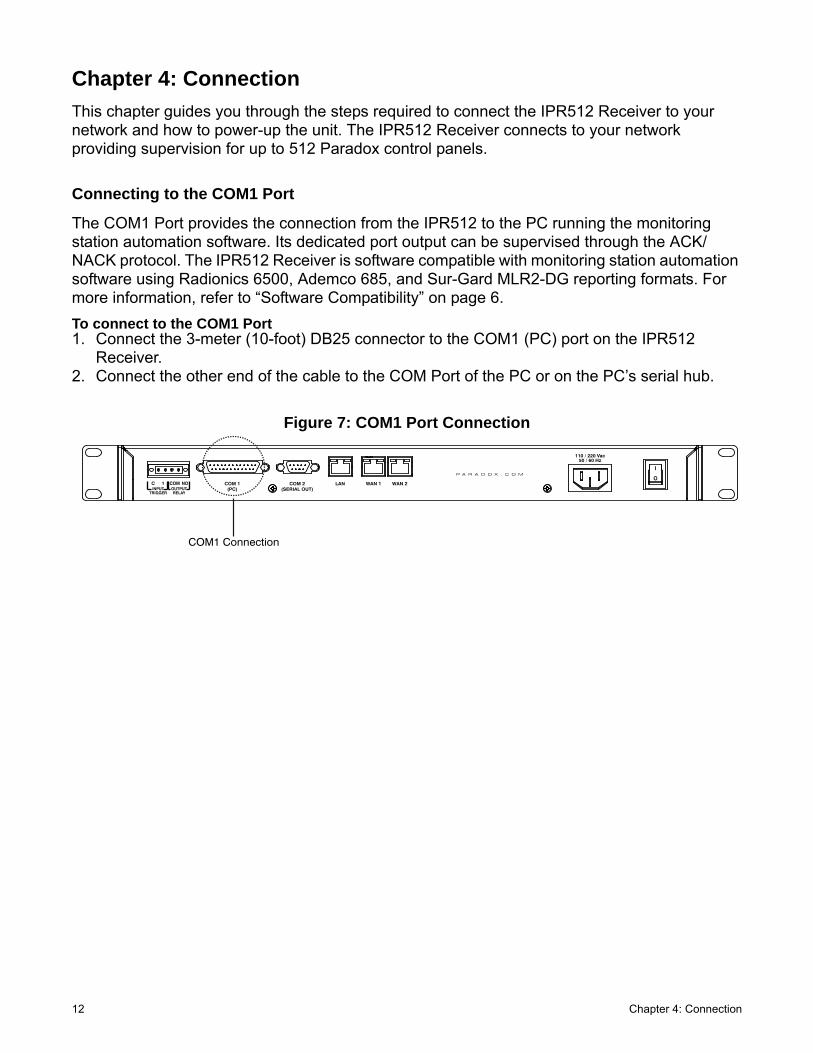
Chapter 4: ConnectionThis chapter guides you through the steps required to connect the IPR512 Receiver to your network and how to power-up the unit. The IPR512 Receiver connects to your network providing supervision for up to 512 Paradox control panels.
Connecting to the COM1 Port
The COM1 Port provides the connection from the IPR512 to the PC running the monitoring station automation software. Its dedicated port output can be supervised through the ACK/NACK protocol. The IPR512 Receiver is software compatible with monitoring station automation software using Radionics 6500, Ademco 685, and Sur-Gard MLR2-DG reporting formats. For more information, refer to “Software Compatibility” on page 6.To connect to the COM1 Port1. Connect the 3-meter (10-foot) DB25 connector to the COM1 (PC) port on the IPR512
Receiver.2. Connect the other end of the cable to the COM Port of the PC or on the PC’s serial hub.
Figure 7: COM1 Port Connection
COM 1(PC)
COM 2(SERIAL OUT)
LAN WAN 1 WAN 2INPUT
TRIGGER
C 1 COM NOOUTPUTRELAY
I
OP A R A D O X . C O M
COM1 Connection

Chapter 4: Connection 13
Connecting to the COM2 Port
The COM2 Port provides the connection to a serial printer or to a PC running a RS-232 serial communication program. The IPR512 Receiver sends reported events in plain text format through the COM2 (RS-232) port, which can be printed or viewed on screen.
To connect to the COM2 Port1. Connect the RS-232 cable’s DB9 connector to the COM2 (Serial Out) port on the IPR512
Receiver.2. Connect the other end of the cable to the COM Port of the printer or PC.Note: A gender changer is included for connection to the COM port of the PC.
Figure 8: COM2 Port Connection
Connecting the LAN Interface
The LAN Port provides the connection to the IPR512 Receiver in order to access the receiver through a Web page interface for configuration. This interface allows the user to view, edit and delete Paradox reporting modules, edit security profiles, configure the IPR512 Receiver, and program special event report codes. For more information on configuring these settings, refer to “IPR512 Receiver Account Management System Overview” on page 21.
To connect to the LAN Port1. Connect a CAT5 network cable to the LAN Port on the IPR512 Receiver.2. Connect the other end of the cable to the router of the network.Note: The router must be installed in the same room as the IPR512 GPRS/IP Monitoring Receiver.
Figure 9: LAN Port Connection
COM 1(PC)
COM 2(SERIAL OUT)
LAN WAN 1 WAN 2INPUT
TRIGGER
C 1 COM NOOUTPUTRELAY
I
OP A R A D O X . C O M
COM2 Connection
COM 1(PC)
COM 2(SERIAL OUT)
LAN WAN 1 WAN 2INPUT
TRIGGER
C 1 COM NOOUTPUTRELAY
I
OP A R A D O X . C O M
LAN Connection

14 Chapter 4: Connection
Connecting the WAN Interfaces
Each IPR512 Receiver provides two WAN ports. Each port can be programmed with its own IP address, thus enabling the IPR512 Receiver to receive events through two different Internet Service Providers (ISPs).
To connect to the WAN Ports1. Connect a CAT5 network cable to the WAN port on the IPR512 Receiver.2. Connect the other end of the cable to the router with internet access on a secured network.Note: The router must be installed in the same room as the IPR512 GPRS/IP Monitoring Receiver.
Figure 10: WAN Port Connections
Installing the Memory Card for Data Backup
The memory card provides up to 10 data backups which are automatically performed 10 minutes after a change has been made in the database or on demand (manually) through the LCD and 6-Button Keypad Interface, for more information, refer to “Chapter 6: IPR512 Receiver LCD System Configuration” on page 42. Stored data includes the receiver’s network, option and serial configuration settings, profile and user information, and system account information for all 512 accounts. For more information on configuring data backups, refer to “Receiver Configuration Menu” on page 30.
A 2GB memory card is included in your package for system backups. The IPR512 Receiver is compatible with the following types of memory cards:
• SD• SD/HC• MMCTo install the Memory Card1. Insert memory card into the Memory Card Slot located in the front of the IPR512 Receiver
(contacts of the memory card should face the bottom).2. Push on the card until it is inserted firmly into the slot. The card pushes out slightly and then
locks into place.
Figure 11: Memory Card Installation
COM 1(PC)
COM 2(SERIAL OUT)
LAN WAN 1 WAN 2INPUT
TRIGGER
C 1 COM NOOUTPUTRELAY
I
OP A R A D O X . C O M
WAN Connections
IP Monitoring ReceiverIPR512
MemoryCard Slot

Chapter 4: Connection 15
Connecting Power
The IPR512 Receiver is powered at 100-240 VAC (50-60 Hz) and is compatible with multiple types of electrical outlets. If you require a different type of power cable, contact your local Paradox dealer for more information. For information on technical specifications refer to “IPR512 Receiver Technical Specifications” on page 7.
To Connect the Power Cable1. Connect one end of the AC Power cable to the AC Power connector on the IPR512
Receiver.2. Connect the other end of the power cable to the electrical outlet or UPS source.
Figure 12: AC Power Connection
Powering up the IPR512 Receiver
When all connections have been completed, turn on the IPR512 Receiver by positioning the On/Off switch to the On position. The IPR512 Receiver will go through an initialization process.
Figure 13: IPR512 Receiver Power-Up
During the IPR512 Receiver’s initialization process, the LCD displays the following messages:
• Message 1 - “Loading data from receiver”.• Message 2 - “Memory card detected”.• Message 3 - Displays the default setting information of the IPR512 Receiver, as shown.
Figure 14: IPR512 Receiver LCD Display Settings
COM 1(PC)
COM 2(SERIAL OUT)
LAN WAN 1 WAN 2INPUT
TRIGGER
C 1 COM NOOUTPUTRELAY
I
OP A R A D O X . C O M
AC PowerConnection
COM 1(PC)
COM 2(SERIAL OUT)
LAN WAN 1 WAN 2INPUT
TRIGGER
C 1 COM NOOUTPUTRELAY
I
OP A R A D O X . C O M
Power Switch
IP Monitoring ReceiverIPR512

16 Chapter 5: System Configuration
Chapter 5: System ConfigurationThis chapter guides you through the steps required to configure the IPR512 Receiver through a web browser connection using the IPR512 Receiver Account Management System.
Accessing the IPR512 Receiver Account Management System
In order to access the IPR512 Receiver Account Management System, the IPR512 must be connected to the same network as the PC. Once a connection has been established configuration settings for your IPR512 Receiver can be set. For more information on how to configure the settings through the LCD menu, refer to “Chapter 6: IPR512 Receiver LCD System Configuration” on page 42.
To Access the IPR512 Receiver Account Management System1. Launch your web browser from a computer on the network connected to the IPR512
Receiver’s LAN port.2. Enter the LAN IP address of IPR512 Receiver in the address bar of your web browser. You
are now presented at the Login page. Speak to your network administrator to obtain an IP Address and Subnet Mask that will permit access to the IPR512 Receiver on your network.
Note: If you cannot connect to the IPR512 Receiver Account Management System, please verify that the LAN IP address was correctly entered into the address bar. If an error page is displayed, the IPR512 Receiver’s IP address and Subnet Mask must be changed through the LCD menu on the IPR512 Receiver. For more information on how to change these settings, refer to “Chapter 6: IPR512 Receiver LCD System Configuration” on page 42.
Figure 15: Accessing the IPR512 Receiver Account Management System
3. Enter your Username. Default username is “admin”.4. Enter your Password. Default password is “admin”.5. Click Login.
Note: When you have logged into the system, it is strongly recommended that the default password be changed for security purposes, note that the username cannot be changed.

Chapter 5: System Configuration 17
Figure 16: Login Page
Table 6: Login Page FieldsItem Description
Username Enter the username. Default username is “admin”.Password Enter the password. Default password is “admin”.Login Press to access the IPR512 Receiver Account Management System. Access will only
be granted when a valid username and password combination has been entered.ID: Identifies the ID number of the IPR512 Receiver.Line: Identifies the line number of the IPR512 Receiver.
adminadmin

18 Chapter 5: System Configuration
Registering the IPR512 Receiver
After logging into the IPR512 Receiver Account Management System for the first time, you will need to register your IPR512 Receiver in order to activate a fully-functional version. By default, the IPR512 Receiver runs in Demo Mode. When in Demo Mode you are limited to 10 accounts and the communication port COM1 is disabled.
To Register the Unit1. Connect the LAN of the IPR512 Receiver to a router on a network with access to the Inter-
net.2. Click Register.
Figure 17: Demo Mode

Chapter 5: System Configuration 19
3. Click on Create a Login if this is your first time registering an IPR512 Receiver. If you have already registered a unit, enter your Login ID and Password and then click on Login.
Figure 18: IPR512 Registration Login Page

20 Chapter 5: System Configuration
4. Click on the Register button. The registration process is now complete. The IPR512 Receiver is registered into the system and the IPR512 Receiver Account Management system is now activated and fully-functional. The Registration window displays the Serial #, Firmware, Bootloader and Hardware version of the IPR512 Receiver you are currently registering.
Note: The latest firmware version, as well as the most current IPR512 Receiver documentation, can be downloaded from the Registration window.
Figure 19: Finalizing the Registration

Chapter 5: System Configuration 21
IPR512 Receiver Account Management System Overview
This section provides an overview of the IPR512 Receiver Account Management System. The IPR512 Receiver Account Management System allows you to configure the receiver’s settings, register the unit, upgrade its firmware, view, edit, and delete registered Paradox reporting modules, and setup security profiles.
The Main Menu, Search, and Information views are always displayed at the top of every menu display of the IPR512 Receiver Account Management System. This allows you to view account and profile information at a glance and provides easy access to the search and main menu functions.
Figure 20: IPR512 Receiver Account Management Overview
Figure 21: IPR512 Receiver Account Management System Overview FieldsItem Description
1 - Main Menu Provides access to the following six menu options:• Accounts - Allows you to access all system accounts.• Security Profiles - Allows you to access and define security profiles• Receiver Configuration - Allows you to configure settings for the IPR512 Receiver.• Event Configuration - Allows you to view account and receiver related events.• Receiver Status - Allows you to view the status of the receiver and system information.• View/Restore Deleted Accounts - Allows you to view deleted accounts, restore accounts, and
permanently delete accounts from the system.2 - Search Provides a search tool that allows you to search by providing a range based on the account
number, range of account numbers or by MAC address. Go runs the search.3 - Receiver Info Displays the IP Receiver ID and line, date and time, the number of accounts and profiles used in
the system, and the number of deleted accounts.4 - Change Password and Logout
Provides access to the Change Password option and allows you to properly log out of the system.
5- Menu Display Displays the contents of the selected menu option.6 - Page Browser Displays the number of pages. Use the next and previous page arrows to go to desired
page.Each page displays a maximum of 20 accounts.

22 Chapter 5: System Configuration
Change Password
The Change Password option allows you to modify the default login password set in the IPR512 Receiver Account Management System. It is recommended, for security purposes, that the password be changed. To change the password, select the Change password option. You are then able to enter a new password and save your settings.
Figure 22: Change Password
Table 7: Change Password FieldsItem Description
Login Name Displays current login name.Current Enter the current password.New Enter the new password (the password can be alphanumeric).Confirm Confirm the new password.Save Save the new changes.

Chapter 5: System Configuration 23
Accounts Menu
The Accounts menu option provides access to all registered accounts. From this menu you can modify existing system accounts and assign security profiles.
Figure 23: Account Page
Table 8: Account Page Menu FieldsItem Description
Status Icon Displays the current status of the account.
Green - Connection established.
Red - No connection established.
Clock - Change in progress.
Account # Displays the account number assigned to the current account.MAC address Displays the MAC address or unique ID assigned to the Paradox reporting module.Security profile Displays the security profile assigned to the current account. For more information on
setting the Security profile values, refer to “Security Profiles Menu” on page 26.Last poll time Displays the last date and time that the account’s IP device sent a presence message
to the IPR512 Receiver at the configured Module Polling Time. For more information on setting the Security profile values, refer to “Security Profiles Menu” on page 26.
Last IP address Displays the IP address of the last IP device that sent a message to the IPR512 Receiver.
IP device Displays the internet module used at the account site.Panel Displays the panel type used at the account site.Registered on Displays the time and date of when the module was registered.

24 Chapter 5: System Configuration
To Modify an Existing Account1. Select the account you wish to modify from the list.2. Click on Edit.3. Select the required Security profile from the drop-down list.4. Click Save to save your changes. To cancel any changes without saving, click the Cancel
option.
Figure 24: Edit Existing Account

Chapter 5: System Configuration 25
To Delete an Existing Account1. Select the account you wish to delete from the list.2. Click on Delete.3. Select Yes to delete or No to cancel your action.
Figure 25: Delete Existing Account

26 Chapter 5: System Configuration
Security Profiles Menu
The Security Profiles menu option provides up to 32 security profiles that can be created for each IPR512 Receiver. Security profiles are used by the IP device to report presence messages to the IPR512 Receiver at the configured Module Polling Time. If the IPR512 Receiver does not receive a presence message within the configured Receiver Supervision Time, the receiver will report a supervision loss to the monitoring station’s automation software. For more information on how to configure a supervision loss, refer to “Event Configuration Menu” on page 33.
Each presence message contains less than 100 bytes of data. When a security profile is modified, the IP device(s) assigned to the profile will automatically be updated during the next Module Polling Time. The following table provides the four security profiles and default polling and supervision times that have been pre-set in the system.
Table 9: Security Profile System Defaults
Note: All the pre-set module Polling and Receiver Supervision Times can be re-configured in the system. Paradox strongly recommends that Receiver Supervision Times be configured with a minimum of one minute and that the Module Polling Time be at least half of the Receiver Supervision Time (e.g., RST: 1 minutes - MPT: 30 seconds).
Figure 26: Security Profiles Menu
ID Name Module Polling Time Receiver Supervision Time00 No Supervision 24 hours None01 High Supervision 2 minute 5 minutes02 Medium Security 10 minutes 30 minutes03 Low Security 20 minutes 1 hour

Chapter 5: System Configuration 27
Table 10: Security Profiles Menu Fields
To Add a Security Profile1. Click Add.2. Define the name, Module Polling Time and Receiver Supervision Time. 3. Click Save to save your changes. To cancel any changes without saving, select the Cancel
option.
Figure 27: Add New Security Profile
Item Description
ID Displays the ID assigned to the Security Profile. This ID is used by the field installer when programming the IP device.
Name Displays the name or description assigned to the Security Profile.Module Polling Time Displays the polling time assigned to the Security Profile.Receiver Supervision Time Displays the time assigned before reporting a supervision loss to the monitoring
station’s automation software.Accounts using this profile Displays the number of accounts to which this security profile is assigned.

28 Chapter 5: System Configuration
To Modify an Existing Security Profile1. Select the Security Profile you wish to modify from the list.2. Click Edit.3. Click Save to save your changes. To cancel any changes without saving, select the Cancel
option.
Note: When a security profile has been modified, all accounts assigned to the security profile will be updated automatically at the next polling time.
Figure 28: Edit Existing Security Profile

Chapter 5: System Configuration 29
To Delete an Existing Security Profile1. Select the Security Profile you wish to delete from the list.2. Click Delete.3. Select Yes to delete or No to cancel your action.
Note: A security profile cannot be deleted if used by one or more accounts.
Figure 29: Delete Existing Security Profile

30 Chapter 5: System Configuration
Receiver Configuration Menu
The Receiver Configuration menu option provides the configuration settings for the IPR512 Receiver. From this menu, you can set WAN and LAN connection settings for communication with the IPR512 Receiver, set COM port settings, language and time zone preferences.
Figure 30: Receiver Configuration Menu

Chapter 5: System Configuration 31
Table 11: Receiver Configuration Menu FieldsItem Description
1 - WAN1, WAN2, LAN
Interface enabled Specifies the type of interface used.
Port Defines the port number assigned. Port numbers can be between 0 to 65535.IP address Defines the IP address assigned to the IPR512 Receiver. Netmask Defines the 32-bit mask used to divide an IP address into subnets and specify the
network’s available hosts.Gateway Defines the Gateway address assigned to the network for communication with
other computers or networks.DNS primary Defines the primary DNS address for translating domain names into IP
addresses.DNS secondary Defines the secondary DNS address for translating domain names into IP
addresses.Note: Speak to your network administrator to obtain these values.
2 - Output Protocol
Output Displays the reporting format used by the IPR512 Receiver. The IPR512 Receiver is compatible with any automation software that uses the Radionics 6500, Ademco 685, and Sur-Gard MLR2-DG standard. Note: SIA reporting is not supported by the Ademco 685 protocol.
Header Defines the byte that will be used to signify the beginning of a message. The header values are defined by the output protocol. Values entered can be between 00 - FF. If 00 is set, the header will not be included.
Trailer Defines the byte that will be used to signify the end of a message. The trailer values are defined by the output protocol. Values entered can be between 01 - FF.
Receiver ID Defines the unique ID assigned to the IPR512 Receiver. Receiver ID can be between 01 and 99.
Line number Defines the line number assigned to the IPR512 Receiver. Line numbers can be between 01 - 34.
ACK/NACK protocol An affirmative or negative response received by the automation software. If this option is enabled, communication with automation software is supervised.
Wait for ACK Defines the amount of time that the IPR512 GPRS/IP Monitoring Receiver will wait for an acknowledgement from the monitoring station’s automation software before sending an “Automation Communication Failure” message.
Note: The system will wait for three attempts before sending the error message.Test message Defines whether a presence message is sent at a defined period intervals to
ensure communication remains active with automation software.Every Defines the interval at which the periodic test message is sent (00 to 99 seconds).
3 - COM Ports
Baud rate Defines the data transfer rate from the IPR512 Receiver to the communication link (RS-232).
Data bits Defines the number of bits used to represent one character of data (most forms of data require eight bits).
Parity Defines whether parity is being used for error detection.Stop bits Defines the number of stop bits used between sending and receiving data.Flow Defines the type of flow control used for the serial port COM1 connection.
4 - Other Configuration
Receiver password Defines the password used for the registration process of the PCS100/IP100. This password must be entered in the control panel when registering a new PCS100/IP100 to the IPR512 Receiver.
Upgrade port Defines the port used for system upgrades. This port number must also be provided in the In-Field Paradox Upgrade Software application.

32 Chapter 5: System Configuration
Polling web site Defines the website address to be polled by the IPR512 Receiver to ensure Internet connection. If no connection is established, a trouble will be set on the LCD, reporting a WAN Internet connection failure.
Date and TimeNTP server Defines the NTP server used for clock synchronization.Time Zone Defines the time zone used at the location of the IPR512 Receiver. It is important
to select the proper time zone to ensure date and times are properly reflected in the IPR512 Receiver Account Management System.
Manual Defines whether date and time information will be configured manually. If configuring the date and time manually, define the month (MM), day (DD), year (YYYY), and time HH:MM (24-hour time format) to ensure that date and times are properly reflected in the IPR512 Receiver Account Management System.
Daylight savings time Defines when the daylight saving time occurs.
To Configure Daylight Savings Time1. Define the start date of DST (Day: DD and Month: MM).2. Define the end date of DST Day: DD and Month: MM).3. Define the day of the week that DST occurs (Monday - Sunday). DST will occur the
day of the week defined after the start date set in Step 1.4. Define the time of day that DST occurs (HH:MM).
Note: Although the date is different each year, you only need to set the start and end date and times once for DST to take effect.
5 - Save all changes
Save Updates and saves all the changes implemented in the Receiver Configuration menu.
Item Description
Chapter 5: System Configuration 33
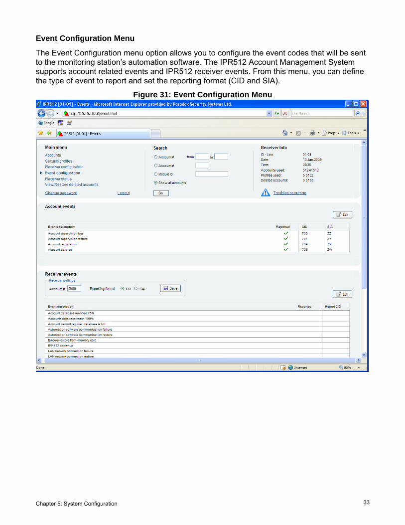
Event Configuration Menu
The Event Configuration menu option allows you to configure the event codes that will be sent to the monitoring station’s automation software. The IPR512 Account Management System supports account related events and IPR512 receiver events. From this menu, you can define the type of event to report and set the reporting format (CID and SIA).
Figure 31: Event Configuration Menu

34 Chapter 5: System Configuration
Account Events
The following account events are pre-set in the system:
• Account supervision loss - sends a message to the monitoring station’s automation soft-ware when communication is lost at the site, for more information, please refer to “Security Profiles Menu” on page 26.
• Account supervision restore - sends a message to the monitoring station’s automation software when communication has been restored at the site, for more information, please refer to the “Security Profiles Menu” on page 26.
• Account registration - sends a message to the monitoring station’s automation software when an account has been registered.
• Account deleted - sends a message to the monitoring station’s automation software when an account has been deleted, for more information, please refer to the “View/Restore Deleted Accounts Menu” on page 39
To Enable and Modify an Account Event
1. Select the Event you wish to modify from the list.2. Click Edit.3. Select whether the event code will be reported. To not report an event, uncheck the
Reported check box.4. Modify the Event code.5. Click Save to save your changes. To cancel any changes without saving, click Cancel.
Figure 32: Edit Existing Account Event
Table 12: Account Event FieldsItem Description
Event description Provides a description of the event.Reported Defines whether the IPR512 Receiver will report special events to the monitoring
station’s automation software.CID Defines the reporting code assigned to the event. This code will be sent the to
monitoring station’s automation software. The CID event code is a 3-digits code.SIA Defines the reporting code assigned to the event. This code will be sent the to
monitoring station’s automation software. The SIA event code is a 2-letter code.

Chapter 5: System Configuration 35
Receiver Events
The following receiver account events are pre-set in the system. The receiver events are sent to the monitoring station’s automation software and to the serial output.
• Memory card not present - sends a message to the monitoring station’s automation soft-ware when the memory card could not be detected in the IPR512 Receiver.
• Memory card error - sends a message to the monitoring station’s automation software when the memory card could not be written to or cannot be initialized.
• Memory card restore - sends a message to the monitoring station’s automation software when “memory card not present” or “memory card error” has been resolved.
• Backup restore from memory card - sends a message to the monitoring station’s automa-tion software when a backup has been restored from the memory card.
• IPR512 power up - sends a message to the monitoring station’s automation software when the IPR512 Receiver has been powered up.
• Automation software communication failure - sends a message to the monitoring sta-tion’s automation software and to the serial output port when communication with the auto-mation software could not be established.
• Automation software communication restore - sends a message to the monitoring sta-tion’s automation software and to the serial output port when communication with the auto-mation software has been restored.
• Account database reached 75% - sends a message to the monitoring station’s automation software when the account database account capacity has reached 75%.
• Account database reached 100% - sends a message to the monitoring station’s automa-tion software when the account database account capacity has reached 100%.
• Account cannot register, database is full - sends a message to the monitoring station’s automation software when an attempt to register has been done on a full database.
• Web login - sends a message to the monitoring station’s automation software when a suc-cessful login attempt has been made via the IPR512 Account Management System.
• NTP server failure - sends a message to the monitoring station’s automation software when communication to the NTP server cannot be established.
• NTP server restore - sends a message to the monitoring station’s automation software when communication to the NTP server is restored.
• LAN network connection failure -sends a message to the monitoring station’s automation software when communication failure has occurred on the LAN.
• LAN network connection restore -sends a message to the monitoring station’s automation software when communication on the LAN has been restored.
• WAN1 network connection failure - sends a message to the monitoring station’s automa-tion software when a network failure has occurred.
• WAN1 network connection restore - sends a message to the monitoring station’s automa-tion software when the network connection has been restored.
• WAN1 internet connection failure - sends a message to the monitoring station’s automa-tion software when communication to the internet (to the polling website defined in the Receiver Configuration menu) via WAN1 cannot be established.
• WAN1 internet connection restore - sends a message to the monitoring station’s automa-tion software when communication to the internet (to the polling website defined in the Receiver Configuration menu) via WAN1 has been restored.
• WAN2 network connection failure - sends a message to the monitoring station’s automa-tion software when a network failure has occurred.

36 Chapter 5: System Configuration
• WAN2 network connection restore - sends a message to the monitoring station’s automa-tion software when the network connection has been restored.
• WAN2 internet connection failure - sends a message to the monitoring station’s automa-tion software when communication to the internet (to the polling website defined in the Receiver Configuration menu) via WAN2 cannot be established.
• WAN2 internet connection restore - sends a message to the monitoring station’s automa-tion software when communication to the internet (to the polling website defined in the Receiver Configuration menu) via WAN2 has been restored.
To Enable and Modify an Receiver Event
1. Enter the IPR512 Receiver’s account number in the account # box.2. Select the reporting format (CID or SIA).3. Click Save. 4. Select the Event you wish to modify from the list.5. Click Edit.6. Select whether the event code will be reported. To not report an event, uncheck the
Reported check box.7. Enter or modify the Event code.8. Click Save to save your changes. To cancel any changes without saving, click Cancel.
Figure 33: Edit Existing Receiver Events
Table 13: Receiver Event FieldsItem Description
Account # Defines the IPR512 Receiver’s account number. When a receiver event is sent to the monitoring station’s automation software, the account number is sent as well in order to track which receiver is reporting the event.
Reporting format Defines the reporting format used by the IPR512 Receiver.CID Select for CID reporting (3-digit code).SIA Select for SIA reporting (2-letter code).Save Updates and save current changes.Event description Provides a description of the event.Reported Defines whether the IPR512 Receiver will report special events to the monitoring
station’s automation software and serial output.Report code Defines the code assigned to the special event. This code will be sent the to
monitoring station’s automation software. Event codes can be either in SIA (2-letters) or CID format (3-digits).

Chapter 5: System Configuration 37
Receiver Status Menu
The Receiver Status menu option displays a listing of all the IPR512 Receiver’s troubles that are occurring on the system and lists the IPR512 Receiver’s system information. Troubles can be viewed in the IPR512 Receiver Account Management System or directly from the IPR512 Receiver’s LCD screen, by entering the troubles menu. For more information on viewing receiver troubles using the LCD screen, refer to “Chapter 7: Troubleshooting and Maintenance” on page 44.
There are two states that the IPR512 Receiver can report, they include:
Note: If troubles are occurring on the system, clicking on the Trouble icon in the Receiver Info section at the top of the IPR512 Receiver Account Management System screen will bring you directly to the Receiver Status menu.
Figure 34: Receiver Status Menu
Table 14: Receiver Status Fields
Status Icon Description
Receiver status is normal.
Receiver is experiencing troubles.
Item Description
Status Displays the status of the IPR512 Receiver.Trouble group Displays the origin of the trouble. Trouble groups include WAN1, WAN2, LAN,
serial, and memoryTrouble description Displays a description of the trouble that is occurring on the IPR512 Receiver.

38 Chapter 5: System Configuration
The following describes the possible trouble descriptions:• WAN1 - Cannot access the polling website or the IP module has not communicated with the
IPR512 Receiver for a period of 1 minute or cannot access the network.• WAN2 - Cannot access the polling website or the IP module has not communicated with the
IPR512 Receiver for a period of 1 minute or cannot access the network.• LAN - Cannot communicate with the network. • Serial - Cannot communicate with the automation software.• Memory - Card not detected or memory card error.
Table 15: Receiver Information Fields
The IPR512 Receiver Account Management System stores a log file that tracks system events and troubles that have occurred on the IPR512 Receiver. It is an XML document that keeps track of the most recent events that have occurred in the system (150 events buffered). The system log file is used for troubleshooting purposes only. To Export the System Log File
1. Select the Export Logged Events button. 2. Select Save to save the IPR251_XX(receiver ID)_XX (line ID)_systemlog.xls or select Open
to open the file. 3. If you have selected the open option, a File Download dialog box will be displayed. Select
the preferred method of opening the file and click OK, select Cancel, to cancel this operation.
Figure 35: Export Logged Events
Item Description
Serial # Displays the serial number of the IPR512 Receiver.MAC address - LAN Displays the MAC address assigned to the LAN. MAC address - WAN1 Displays the MAC address assigned to the WAN1.MAC address - WAN2 Displays the MAC address assigned to the WAN2.Firmware Current Version Displays the firmware version that installed in the IPR512 Receiver.Firmware Latest Version Displays the most current version of firmware available. If the most recent is
installed on the receiver, then the latest version will not be displayed.Bootloader Displays the bootloader version installed on the IPR512 Receiver.Hardware Displays the hardware version of the IPR512 Receiver.Registered on Displays the date the IPR512 Receiver was registered.
Chapter 5: System Configuration 39
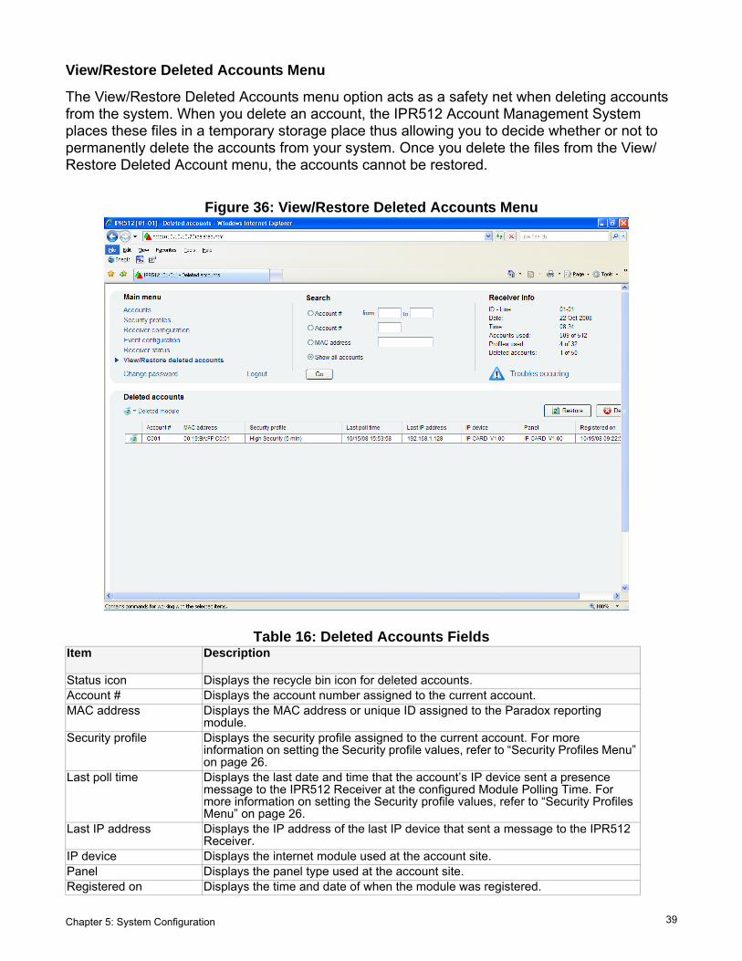
View/Restore Deleted Accounts Menu
The View/Restore Deleted Accounts menu option acts as a safety net when deleting accounts from the system. When you delete an account, the IPR512 Account Management System places these files in a temporary storage place thus allowing you to decide whether or not to permanently delete the accounts from your system. Once you delete the files from the View/Restore Deleted Account menu, the accounts cannot be restored.
Figure 36: View/Restore Deleted Accounts Menu
Table 16: Deleted Accounts FieldsItem Description
Status icon Displays the recycle bin icon for deleted accounts.Account # Displays the account number assigned to the current account.MAC address Displays the MAC address or unique ID assigned to the Paradox reporting
module.Security profile Displays the security profile assigned to the current account. For more
information on setting the Security profile values, refer to “Security Profiles Menu” on page 26.
Last poll time Displays the last date and time that the account’s IP device sent a presence message to the IPR512 Receiver at the configured Module Polling Time. For more information on setting the Security profile values, refer to “Security Profiles Menu” on page 26.
Last IP address Displays the IP address of the last IP device that sent a message to the IPR512 Receiver.
IP device Displays the internet module used at the account site.Panel Displays the panel type used at the account site.Registered on Displays the time and date of when the module was registered.

40 Chapter 5: System Configuration
To Restore a Deleted Account 1. Select the account you wish to restore from the list.2. Click on Restore.3. Select Yes to delete or No to cancel your action.
Figure 37: Restore Deleted Account

Chapter 5: System Configuration 41
To Permanently Delete a Deleted Account 1. Select the account you wish to delete from the list.2. Click on Delete.3. Select Yes to delete or No to cancel your action.
Figure 38: Permanently Delete a Deleted Account

42 Chapter 6: IPR512 Receiver LCD System Configuration
Chapter 6: IPR512 Receiver LCD System ConfigurationThis chapter guides you through the steps required to configure the IPR512 Receiver using the LCD display and Keypad Interface located on IPR512 Receiver. These steps can be used if you are experiencing difficulties with the IPR512 Account Management System. For more information on how to configure the IPR512 Receiver using the IPR512 Account Management System, refer to “Chapter 5: System Configuration” on page 16. The backlight and contrast settings are also described.
Note: Some of the menu options are password protected. Enter the password that is used when logging into the IPR512 Receiver Account Management System. The default password is set to admin.
Setting the IP Address, Port and Subnet Mask
By default, the IPR512 Receiver is configured with a default IP address, port and subnet mask. For more information on the IPR512 Receiver’s system defaults, refer to “IPR512 Receiver System Defaults” on page 6. The default settings can be re-configured if communication cannot be established with your network. The defaults can be configured through the IPR512 Receiver’s LCD menu. To Configure the IPR512 Receiver IP Address, Port and Subnet Mask1. Press OK to access the Main Menu on the IPR512 Receiver. If there are any troubles,
pressing OK will enter the Trouble Menu. If this occurs, press X to access the Main Menu.2. Use the Up/Down arrows and scroll to “LAN settings” and press OK.3. Enter your password. Use the Up and Down arrows to change the value, use the Left and
Right arrows to scroll. Press OK when done.4. The LCD will display “LAN IP Addr/Port” and “LAN Subnet mask” menu, use the Up and
Down arrows to change the value, use the Left and Right arrows to scroll. Press OK when done.
5. Change the Port and press OK when done. The port must be a five digit value, therefore when providing a port number of i.e. 80, it must be entered as 00080.
6. Use the Up and Down arrows to change the LAN Subnet Mask and use the Left/Right arrows to scroll. Press OK when done.
The LCD screen will display “New LAN Settings saved”.
Figure 39: IPR512 Receiver LAN, IP and Port SettingsIP Monitoring ReceiverIPR512

Chapter 6: IPR512 Receiver LCD System Configuration 43
The backlight and the contrast levels can also be configured directly on the IPR512 Receiver. The following section describes these settings.To Set the Contrast1. Press OK to access the Main Menu on the IPR512 Receiver. If there are any troubles,
pressing OK will enter the Trouble Menu. If this occurs, press X to access the Main Menu.2. Use the Up/Down arrows and scroll to “LCD settings” and press OK.3. Use the Up/Down arrows and scroll to “Set Contrast”. The LCD will display the selected
menu item.4. Use the Left and Right arrows to change the value and press OK when done. Press X to quit
without saving.
Figure 40: IPR512 Receiver Contrast Setting
To Set the Backlight1. Press OK to access the Main Menu on the IPR512 Receiver. If there are any troubles,
pressing OK will enter the Trouble Menu. If this occurs, press X to access the Main Menu.2. Use the Up/Down arrows and scroll to “LCD settings” and press OK.3. Use the Up/Down arrows and scroll to “Set backlight”. The LCD will display the selected
menu item.4. Use the Left and Right arrows to change the value and press OK when done. Press X to quit
without saving.
Figure 41: IPR512 Receiver Backlight Setting
IP Monitoring ReceiverIPR512
IP Monitoring ReceiverIPR512

44 Chapter 7: Troubleshooting and Maintenance
Chapter 7: Troubleshooting and MaintenanceThis chapter provides a listing of the troubles that may be present on the IPR512 Receiver. System backup procedures and firmware upgrades are also described.
Troubles Overview
The IPR512 Receiver provides several LED status indicators to indicate if any critical errors have occurred. If a trouble occurs on the IPR512 Receiver, the Trouble LED will turn on. The LCD screen will then display a message indicating the number of troubles that have occurred. When all the troubles have been resolved, the Trouble LED will then turn off. Refer to “LCD Menu” on page 45 for a listing of the different types of troubles that may occur on the IPR512 Receiver. Refer to Table 17: LED Status Indicators for a description of the LEDs.To View Troubles
1. Press OK to enter the Trouble Menu.2. Use the Up and Down arrows to scroll and view messages. The LCD will display the trouble
that has occurred.3. Press OK when done.
Figure 42: Viewing Troubles
Table 17: LED Status IndicatorsLED Color Description
Data GreenOff
Memory card is being accessed.Memory card not in use.
WAN1 OK Green
OffNetwork connection is detected on WAN1 port.IPR512 Receiver cannot access the network.
Data GreenOff
Sending or receiving data through WAN1 port.IPR512 Receiver cannot access the polling web site or IP modules are not communicating with the receiver for a period of 1 minute.
WAN2 OK Green
OffNetwork connection is detected on WAN2 port.IPR512 Receiver cannot access the network.
Data GreenOff
Sending or receiving data through WAN2 port.IPR512 Receiver cannot access the polling web site or IP modules are not communicating with the receiver for a period of 1 minute.
LAN GreenOff
Sending or receiving data through LAN port. Not communicating with the network.
Serial GreenOff
Connection is established with the automation software.IPR512 Receiver is not communicating with the automation software or ACK/NACK is not enabled.
Troubles Red Trouble is detected on the IPR512 Receiver. Troubles can be viewed through the LCD screen.
AC GreenOff
Power is present.No power detected.
IP Monitoring ReceiverIPR512

Chapter 7: Troubleshooting and Maintenance 45
Figure 43: LCD MenuLCD Menu
View Troubles
Backup Menu
LAN Settings
LCD Settings
Restore Factory Settings
No TroubleTrouble(s)
Backup data on memory card
Restore data from memory card
Memory card not detected
LAN network connection failure
This will erase all contents Press [OK] to continue, [X] to abort
Set contrast< | | | | | | | | | | | >
Set backlight
Set contrast
Set backlight< | | | | | | | | | | | >
New LAN setting saved
LAN IP address invalidenter value between 0 and 255
LAN IP Addr/Port: 192.168.001.250 / 00000LAN Subnet mask: 255.255.255.000
LAN TCP Port invalidenter value between 1 and 65535LAN Subnet mask address invalidenter value between 0 and 255
Copying data on memory cardDo not remove memory card xxx/557Kb
No backup availablePress [OK] to continue10 backups availablePress [OK] to continue
2008-07-30 13:55 ID: 01 Line: 012008-07-30 11:55 ID:01 Line:01
This will overwrite contents of ReceiverPress [OK] to continue, [X] to abort
Data from another IPR512 (ID: xx Line: xx)Press [OK] to continue, [X] to abort
Shutdown IPR512 ID: xx Line: xxPress [OK] to continue, [X] to abort
Receiver will reboot Restoring backup from memory card
WANx network connection failure
Memory card not detectedMemory card init failed
* Note: To view more than one trouble, use the up and down arrows on the LCD keypad.
WANx Internet connection failure
Time Server unreachable
Enter password
Enter password
Enter password
Receiver will reboot
Time Server unreachable

46 Chapter 7: Troubleshooting and Maintenance
System Backup Overview
The IPR512 Receiver provides up to 10 data backups to the memory card which are automatically performed 10 minutes after a change has been made in the database or on demand (manually) through the LCD and 6-Button Keypad Interface. Stored data includes the receiver’s configuration settings and all system account information. The last ten backups are kept on the memory card. If the IPR512 Receiver experiences a crash, fast and easy substitution of memory cards from one receiver to another provides practically no down time for recovery situations.
To Conduct a System Backup 1. Press OK on the IPR512 Receiver to access the Main Menu. If there are any troubles,
pressing OK will enter the Trouble Menu. If this occurs, press X to access the Main Menu.2. Use the Up/Down arrows and scroll to “Backup menu” and press OK.3. Enter your password. Use the Up and Down arrows to change the value, use the Left and
Right arrows to scroll. Press OK when done.4. Select “Backup data on memory card” and press OK. The IPR512 Receiver will then begin
copying data on the memory card. Do not remove the Memory Card from the Memory Card Slot until backup is complete.
Figure 44: IPR512 Receiver System Backup
To Conduct a Restore from a Backup1. Press OK on the IPR512 Receiver to access the Main Menu. If there are any troubles,
pressing OK will enter the Trouble Menu. If this occurs, press X to access the Main Menu.2. Use the Up/Down arrows and scroll to “Backup menu” and press OK.3. Enter your password. Use the Up and Down arrows to change the value, use the Left and
Right arrows to scroll. Press OK when done.4. Select “Restore data from memory card” and press OK. The IPR512 Receiver will then
display the backups that are currently available.5. Select the appropriate backup by using the Up and Down arrow keys, press OK to accept.
The IPR512 Receiver will display message “This will overwrite contents of IPR512”. Press OK to accept and the receiver will reboot or press X to cancel this procedure.
Figure 45: IPR512 Receiver Restore from Backup
IP Monitoring ReceiverIPR512
IP Monitoring ReceiverIPR512

Chapter 7: Troubleshooting and Maintenance 47
To Restore Backup from another IPR512 Receiver1. Remove the memory card from the problematic IPR512 Receiver.2. Insert the memory card into the Memory Card Slot of the new IPR512 Receiver.3. Press OK on the receiver to access the Main Menu. If there are any troubles, pressing OK
will enter the Trouble Menu. If this occurs, press X to access the Main Menu.4. Use the Up/Down arrows and scroll to “Backup menu” and press OK.5. Enter your password. Use the Up and Down arrows to change the value, use the Left and
Right arrows to scroll. Press OK when done.6. Use the Up/Down arrows and scroll to “Restore data from memory card”. The LCD will
display the selected menu item. At this point the IPR512 Receiver will prompt you that there is data from another IPR512 (ID: XX Line: XX).
7. Select OK to overwrite contents currently on the system or X to cancel the procedure. If you select OK the receiver will reboot and copying of data will begin.
8. Select OK to shutdown the receiver or X to cancel. If you select OK, the receiver will then copy data and then reboot.
Do not remove the Memory Card from the Memory Card Slot until backup is complete.
Figure 46: IPR512 Receiver RestoreIP Monitoring ReceiverIPR512

48 Chapter 7: Troubleshooting and Maintenance
Firmware Upgrade Overview
The IPR512 Receiver’s firmware* can be upgraded using the In-Field Paradox Upgrade Software application. From this application, you can specify the IPR512 Receiver or IP Module to upgrade and which software version to install. When you confirm the update, the IPR512 Receiver or IP Module will be upgraded with the newest update and will be up and running in less than 90 seconds. *Automatic firmware upgrade not supported by current version. Please check the web for updates.
Accessing the In-Field Paradox Upgrade Software Application
In order to access the In-Field Paradox Upgrade Software Application, the application must first be installed on your hard drive. The In-Field Paradox Upgrade Software Application can also be downloaded from the Paradox website at www.paradox.com.To Access the In-Field Paradox Upgrade Software Application1. Locate the InField.exe file on your PC or double-click the In-Field icon from your desktop. 2. If the icon is not on your desktop, double-click on the executable file to launch the In-Field
Paradox Upgrade Software application.
When the application is launched, the Main screen is then displayed, as shown in Figure 47: In-Field Paradox Upgrade Software Application.
Figure 47: In-Field Paradox Upgrade Software Application

Chapter 7: Troubleshooting and Maintenance 49
To Upgrade Firmware using a Serial Connection
Before beginning the upgrade process, ensure that the serial cable is connected between the COM2 Port of the IPR512 Receiver and your PC. Ensure that the Serial Tab is selected from the In-Field Paradox Upgrade Software window.
Step 1: Define Communication Settings
1. Select the communication port to be used from the Port drop-down list. 2. Select the transfer speed from the Transfer Maximum Speed drop-down list (automatic is
recommended).3. Proceed to Step 2.
Figure 48: Communication Settings

50 Chapter 7: Troubleshooting and Maintenance
Step 2: Select Devices
1. Press the Connect/Refresh button. A Progress dialog box will appear. The progress dialog box detects the connection to the port.
2. Select the Product to update from the list.3. Proceed to Step 3.
Note: When conducting a firmware upgrade through a serial connection, you can only upgrade the IPR512 Receiver to which you are currently connected to.
Figure 49: Select Devices
Chapter 7: Troubleshooting and Maintenance 51
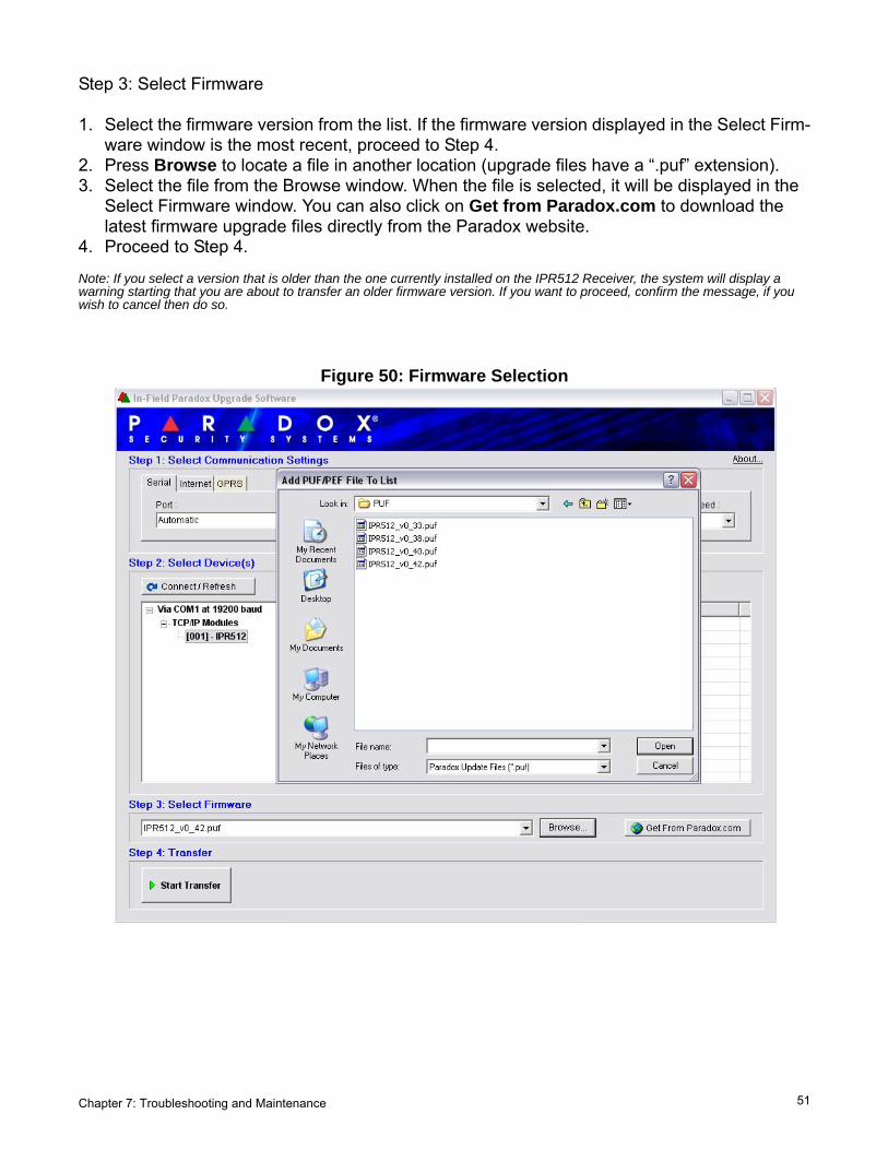
Step 3: Select Firmware
1. Select the firmware version from the list. If the firmware version displayed in the Select Firm-ware window is the most recent, proceed to Step 4.
2. Press Browse to locate a file in another location (upgrade files have a “.puf” extension).3. Select the file from the Browse window. When the file is selected, it will be displayed in the
Select Firmware window. You can also click on Get from Paradox.com to download the latest firmware upgrade files directly from the Paradox website.
4. Proceed to Step 4.
Note: If you select a version that is older than the one currently installed on the IPR512 Receiver, the system will display a warning starting that you are about to transfer an older firmware version. If you want to proceed, confirm the message, if you wish to cancel then do so.
Figure 50: Firmware Selection

52 Chapter 7: Troubleshooting and Maintenance
Step 4: Transfer
1. Press the Start Transfer button.The system will then display a Progress dialog box. 2. Exit the application once the upgrade is complete.
Figure 51: Transfer Process
Chapter 7: Troubleshooting and Maintenance 53
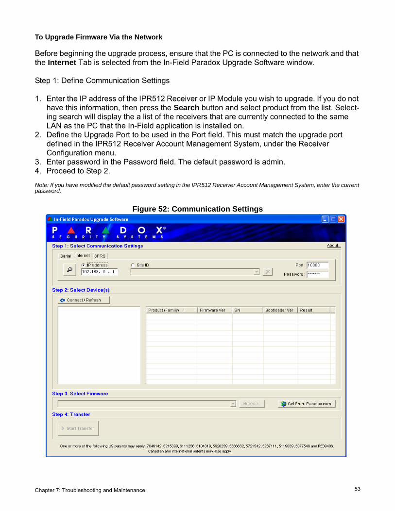
To Upgrade Firmware Via the Network
Before beginning the upgrade process, ensure that the PC is connected to the network and that the Internet Tab is selected from the In-Field Paradox Upgrade Software window.
Step 1: Define Communication Settings
1. Enter the IP address of the IPR512 Receiver or IP Module you wish to upgrade. If you do not have this information, then press the Search button and select product from the list. Select-ing search will display the a list of the receivers that are currently connected to the same LAN as the PC that the In-Field application is installed on.
2. Define the Upgrade Port to be used in the Port field. This must match the upgrade port defined in the IPR512 Receiver Account Management System, under the Receiver Configuration menu.
3. Enter password in the Password field. The default password is admin. 4. Proceed to Step 2.
Note: If you have modified the default password setting in the IPR512 Receiver Account Management System, enter the current password.
Figure 52: Communication Settings

54 Chapter 7: Troubleshooting and Maintenance
Step 2: Select Devices
1. Press the Connect/Refresh button. A Progress dialog box will appear. The progress dialog box detects the connection to the network in order to display results.
2. Select the Product to update from the list.3. Proceed to Step 3.
Figure 53: Select Devices

Chapter 7: Troubleshooting and Maintenance 55
Step 3: Select Firmware
1. Select the firmware version upgrade from the list. If the firmware version displayed in the Select Firmware window is the most recent, proceed to Step 4.
2. Press Browse to locate a file in another location, upgrade files have a “.puf” extension. Select the file from the Browse window. Once the file is selected, it will be displayed in the Select Firmware window. Select Get From Paradox.com to download the latest firmware upgrade directly from the Paradox website.
3. Proceed to Step 4.
Note: If you select a version that is older than the one currently installed on the IPR512 Receiver, the system will display a warning starting that you are about to transfer an older firmware version.
Figure 54: Firmware Selection

56 Chapter 7: Troubleshooting and Maintenance
Step 4: Transfer
1. Press the Start Transfer button.The system will then display a Progress dialog box. 2. Exit the application once the upgrade is complete.
Figure 55: Transfer Process

Chapter 8: Initiating Communication with the IPR512 Receiver 57
Chapter 8: Initiating Communication with the IPR512 ReceiverOnce the installation and configuration settings have been completed, the next step is to register the Paradox reporting modules to the IPR512 Receiver.
Registering the Paradox Reporting Modules
No monitoring station operator action is required to register an Paradox reporting module. Registration is initiated by the installer upon installation of the Paradox reporting module. However, the monitoring station must provide the installer with the following information that is entered by the installer.
• Account # for each partition of the site.• IP Address and Port of the IPR512 Receiver(s) you wish that the site to report to.• Receiver Password (1 to 32 digits). For more information on setting the Receiver Pass-
word, refer to “Receiver Configuration Menu” on page 30.• Security Profile (2 digits). For more information on Security Profiles, refer to “Security Pro-
files Menu” on page 26.
Once the installer has entered this information, the installer then initiates communication with the IPR512 Receiver and the Paradox reporting module will be automatically registered in the receiver.

58
IndexNumerics19" Rack ..........................................................1032 polling profiles ............................................266-Button Keypad Interface ........................14, 46
AAC ...................................................................44AC Input ............................................................9AC Power Cable .............................................15AC Power Status LED .......................................8Account # ..................................................23, 39Account cannot register, database is full ........35Account database reached 100% ...................35Account database reached 75% .....................35Account deleted ..............................................34Account Registration .......................................34Account Status Icon ........................................23Account Supervision Loss .........................34, 35Account Supervision Restore ..........................34Accounts using this profile ..............................27ACK/NACK protocol ........................................31Activate ...........................................................20Add a Security Profile .....................................27Address Bar ....................................................16Automatic Update Verification Process ...........48Automation software communication failure ...35Automation software communication restore ..35
BBacklight .........................................................43Backup Procedures .........................................44Backup restore from memory card ..................35Backups ..........................................................46Baud rate ........................................................31Bootloader .......................................................38
CCAT5 Network Cable ......................................13Change Password .....................................21, 22Code .........................................................34, 36COM Ports ......................................................31COM1 Port ........................................................9COM2 Port ........................................................9Communication Settings ...........................49, 53Confirm ...........................................................22Connections
COM1 .......................................................12COM2 .......................................................13LAN Port ...................................................13Power .......................................................15WAN ports ................................................14
Contrast ..........................................................43Control Keypad .................................................8
Create Login ....................................................19Critical Errors ..................................................44Current ............................................................22
DData .................................................................44Data Backup ....................................................14Data Bits ..........................................................31Data Status LED ...............................................8Daylight Savings Time ....................................32Delete an Existing Account .............................25Delete an Existing Security Profile ..................29Demo Mode .....................................................18Desktop Mounting Feet .....................................8Devices .....................................................50, 54Dimensions .......................................................7DNS primary ....................................................31DNS secondary ...............................................31
EEnabled ...........................................................36Event Configuration Menu ...............................33Event Description ..........................34, 36, 37, 38EVO192 .............................................................6EVO48 ...............................................................6EVO64 Keypads ................................................6Export Logged Events .....................................38
FFirmware .........................................................44Firmware Current Version ...............................38Firmware Latest Version .................................38Firmware Upgrade ....................................44, 48Firmware Upgrade via the Network .................53Flow .................................................................31
GGateway ..........................................................31
HHardware .........................................................38
IID .....................................................................27In-Field Paradox Upgrade Software ..........48, 53Info ..................................................................21Input ..................................................................7Input Power .......................................................7Input Triggers ....................................................9Input Voltage .....................................................7Interface Enabled ............................................31Internet Tab .....................................................53IP Address .................................................31, 42IP device .........................................................39IP Module ........................................................48

59
IP100 .................................................................6IPR512 power up ............................................35IPR512 Receiver
Dimensions .................................................7Environmental Requirements ...................12Software Compatibility ................................6
IPR512 Receiver Account Management System 16, 21
LLAN .......................................................9, 38, 44LAN Interfaces ................................................13LAN network connection failure ......................35LAN network connection restore .....................35LAN Status LED ................................................8Last IP address ...............................................39Last Poll time ............................................23, 39LCD ...........................................................15, 44LCD Configuration ..........................................42LCD Display ......................................................8LCD Programming Screens ............................16LED Status Indicators .....................................44Line # ..............................................................31Login ...............................................................19Login Name .....................................................22Logout .............................................................21
MMAC address ............................................23, 39MAC address - LAN ........................................38MAC address - WAN1 .....................................38MAC address - WAN2 .....................................38Main Menu ......................................................21Manual Time Zone ..........................................32MAXIMUS .........................................................6Memory ...........................................................38Memory card error ..........................................35Memory card not present ................................35Memory card restore .......................................35Memory Card Slot .............................................8Menu Display ..................................................21Modify an Existing Account .............................24Modify an Existing Security Profile ..................28Modify an Supervision Loss Event Code 34, 36, 38Module Polling Time .......................................27
NName ..............................................................27Netmask ..........................................................31New .................................................................22New Lan Settings Saved .................................42NTP server ......................................................31NTP server failure ...........................................35NTP server restore ..........................................35
OOn/Off Switch ..................................................15Operating Temperature .....................................7Other Configuration .........................................31Output Format .................................................31Output Relay .....................................................9Output Voltage ..................................................7
PPackage Contents .............................................3Page Selector ..................................................21Panel .........................................................23, 39Parity ...............................................................31Password ................................22, 42, 46, 47, 53PCS100 GPRS Module .....................................6Periodic Interval ..............................................31Periodic Test Message ....................................31Permanently Delete a Deleted Account ..........41Polling Profiles ................................................26Polling Web Site ..............................................31Port ............................................................31, 42Power Switch ....................................................9Power Up ........................................................15Protocol Header ..............................................31Protocol Trailer ................................................31
RRack-Mounting Bracket .....................................8Receiver Configuration ....................................31Receiver Configuration Menu ..........................30Receiver Events ..............................................35Receiver ID .....................................................31Receiver Password .........................................31Receiver Status menu .....................................37Receiver Supervision Time .............................27Register ...........................................................18Registered on ............................................38, 39Registration Login Page ..................................19Restore ......................................................46, 47Restore a Deleted Account .............................40
SSave ................................................................22SD Memory Card ............................................14Search .............................................................21Security Profiles ........................................23, 39Security Profiles Menu ....................................26Select Firmware ........................................51, 55Serial .........................................................38, 44Serial Port Status LED ......................................8Set backlight ....................................................43Set Contrast ....................................................43SIA ..................................................................34SIMS II ..............................................................6

60
Software Compatibility ......................................6Special Event Reporting .................................32Start Transfe .............................................52, 56Start-up ...........................................................15Stop Bits ..........................................................31Subnet Mask ...................................................42System Backup ...............................................46System Components .....................................8, 9System Configuration ......................................16System Log File ..............................................38
Ttemporary storage ...........................................39Time Zone .......................................................32Transfer .....................................................52, 56Trouble group ..................................................37Trouble Status LED ...........................................8Troubles ....................................................37, 44Troubleshooting ..............................................44
UUpgrade port ...................................................31
VView Troubles .................................................44View/Restore Deleted Accounts Menu ...........39
WWAN1 ....................................................9, 38, 44WAN1 internet connection failure ...................35WAN1 internet connection restore ..................35WAN1 network connection failure ...................35WAN1 network connection restore .................35WAN1 Status LED ............................................8WAN2 ....................................................9, 38, 44WAN2 internet connection failure ...................36WAN2 internet connection restore ..................36WAN2 network connection failure ...................35WAN2 network connection restore .................36Web Browser ..................................................16Web login ........................................................35WINSAMM ........................................................6


We hope this product performs to your complete satisfaction. Should you have any questions or comments, please visit us at www.paradox.com.
WWW.PARADOX.COM
Printed in Canada 05/2009 IPR512-EI04


![[Code List] E65/E66 Available Coding List Page 1 of 8morski-online.pl/ftp/e65-e66-available-coding-list.pdf · New Posts Private Messages FAQ ... englisch english [Code List] E65/E66](https://static.documents.pub/doc/80x56/5a856b6e7f8b9ac96a8c628f/code-list-e65e66-available-coding-list-page-1-of-8morski-posts-private-messages.jpg)


