Events per Phone Model ......................................................................................... 698 Series - 4068 ................................................................................................................................ 70e-reflex Series - 4035 ....................................................................................................................... 72
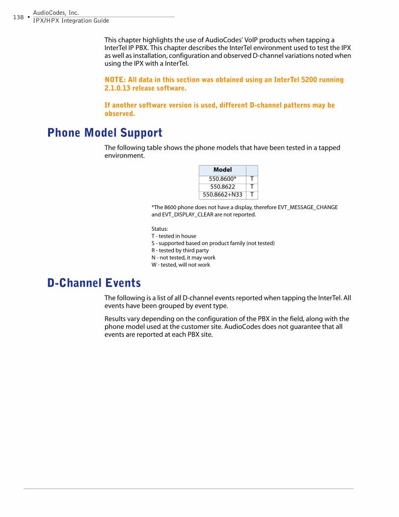
Avaya IP PBX / Office IP PBX . . . . . . . . . . . . . . . . . . . . . . . . . 77Phone Model Support .............................................................................................. 78D-Channel Events .................................................................................................... 78
Events per Phone Model ......................................................................................... 905620SW .......................................................................................................................................... 904610SW .......................................................................................................................................... 94
NEC Neax 2400 IPX Behavior ............................................................................... 156CODEC Support ............................................................................................................................. 156Evt_Station_Removed .................................................................................................................... 156Dialed Numbers (DTMF) Detection ................................................................................................. 156CallerID ......................................................................................................................................... 156Call Progress Tones (CPT) ............................................................................................................. 157PBX Command Events.................................................................................................................... 158Call Control Events......................................................................................................................... 159
Events per Phone Model ....................................................................................... 164Call Scenarios ................................................................................................................................ 165
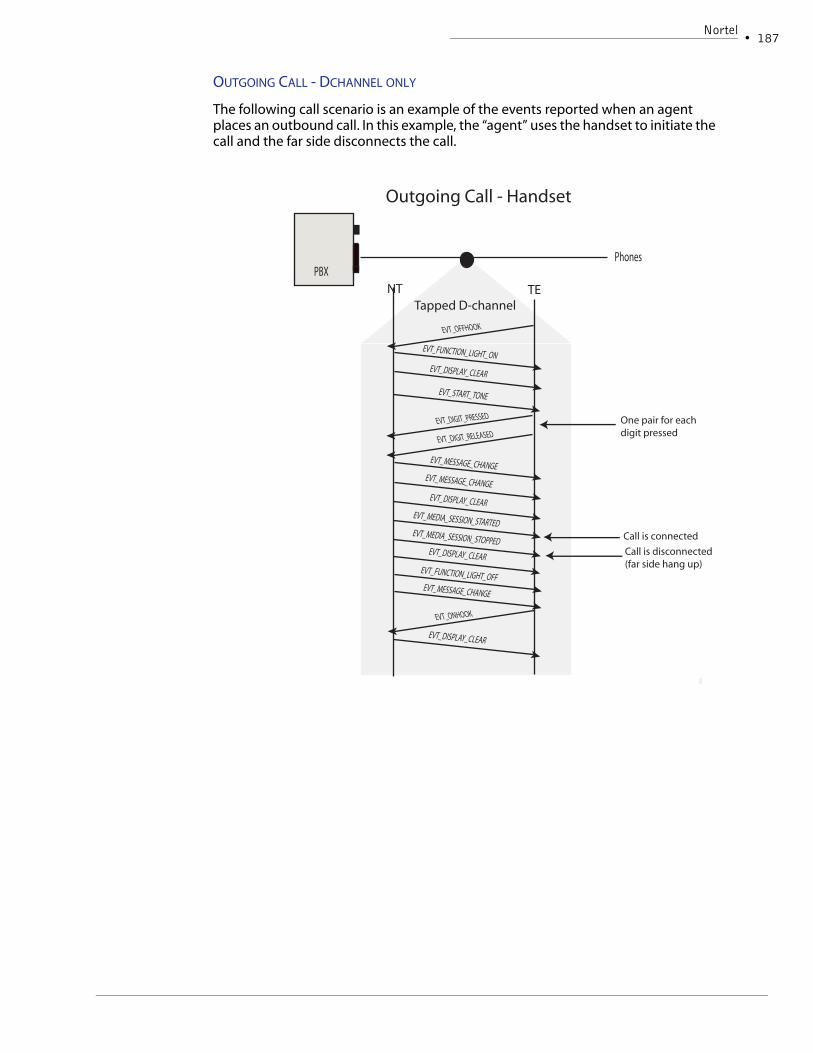
Call Control Events......................................................................................................................... 179Events per Phone Model ....................................................................................... 184
Product OverviewAudioCodes USA’s VoIP patent pending product line supports passive, near real-time IP call recording. This family of products serve the same purpose as AudioCodes’ traditional PSTN based call recording products but for the VoIP environment. The following components make up the complete family line:
IPX /IPX-C
A full-sized PCI board capable of packet filtering, decoding multiple VoIP proto-cols, identifying media RTP packets, and forwarding media packets to a record-ing destination. Ideal when combining multiple tap locations with a single recording apparatus. The IPX product is patent pending.
TX100 and TX100i
A high impedance front end allows users to tap an ethernet line without intro-ducing a point of failure. The TX100 is a stand alone box which can be intro-duced anywhere on the network, while the TX100i must be installed in a server.
Chapter DescriptionsThis book explains the features and capabilities of the components which make up AudioCodes’ VoIP family of products. Each chapter is described below:
• Chapter Two; An Introduction to VoIP Recording - provides a look at the basic design of a VoIP recording solution.
• Chapter Three; About the IPX - describes the capabilities of the IPX along with a detailed discussion of design principles and board logic.
• Chapter Four; Installing the IPX - complete installation instructions including a description of on-board LEDs, and steps for testing board readiness after installation
• Chapter Five; IPX Development - provides a high level explanation of how to use the SmartWORKS API to configure and control the IPX.
• Chapter Six + - provides real life examples when using the IPX to tap each PBX environment.
• Appendix A - a quick reference list of protocol specific parameters needed when enabling each protocol on the IPX .
IntroductionDocument Version Control
• 3
Document Version ControlThe following has been added to this document since the last release:
Contacting AudioCodes USA Your feedback is important to maintain and improve the quality of our products. Use the information below to request technical assistance, make general inquiries, or to provide comments.
TECHNICAL SUPPORT
For programming, installation, or configuration assistance, use the following contact methods:
• Call technical support at 732.469.0880 or call toll free in the USA at 800.648.3647.
• E-mail technical support at [email protected]. Be sure to include a detailed description of the problem along with PC configuration, AudioCodes hardware, driver versions, firmware versions, a sample program that demonstrates the issue, and any other pertinent information.
SALES AND GENERAL INFORMATION
For sales and general information, use the following contact methods:
• Call us at 732.469.0880 or toll free from the USA at 800.648.3647.
Ship packages or send certified mail to us at the following address:
AudioCodes USA, Inc.
27 World’s Fair Drive
Somerset, NJ 08873
AudioCodes, Inc.IPX/HPX Integration Guide6 •
Chapter 2An Introduction to VoIP Recording
AudioCodes, Inc.IPX/HPX Integration Guide8 •
OverviewVoIP - also known as Internet telephony, IP telephony, packet-voice, packetized voice, or voice over IP - transmits voice traffic in the form of packets over standard TCP/IP networks. The convergence of data and voice in the communications market allows for value-added services not available on traditional circuit-based networks, not to mention cost saving advantages. VoIP technology enables businesses to reduce costs, consolidate and simplify networks, and improve customer service applications. VoIP, once viewed as just a new technology, is now recognized as a reliable and cost-effective business solution.
To remain competitive, businesses that develop call recording applications must now implement VoIP solutions. This chapter introduces VoIP recording and differentiates it from traditional circuit-based recording. It begins with an overview of the IP telephony network then examines the unique challenges of VoIP call recording. Readers are then introduced to, AudioCodes’ suite of hardware components designed to support a VoIP call recording application.
VoIP TopologiesTraditional PSTN systems are designed with circuit switched networks. In a circuit switched network each station is a physical element on the network. VoIP networks are essentially connectionless and do not rely on physical channels. VoIP networks are designed around a typical IP network which consists of interconnected routers that form a packet switching fabric.
The simplest VoIP network requires the addition of a VoIP call control server, such as a Call Agent. This server provides the logic and control functions required to maintain the call state. In this scenario, the phone call from the Internet enters the local network via the router or gateway. Signaling information passes to the Call Agent, which then sets up and manages the call. The voice conversation passes directly from the router to the IP phone via LAN switches. Unlike most circuit-based systems, where voice traffic typically passes along the same line as signaling traffic, VoIP technology separates the two.
Call Agent
Voice Packets
Call Control
An Introduction to VoIP RecordingVoIP Topologies
• 9
HYBRID NETWORKS
VoIP networks can also be designed to interface with a conventional PSTN network, usually a T1 or E1 line. In this situation, a Gateway is used to convert traffic between the two networks. In some scenarios, the local phone network consists entirely of IP telephones and a Call Agent manages call states. In other environments, the local phone system is a combination of VoIP and conventional PSTN phones. In this case, call control requires both a Call Agent, and a conventional PBX. Alternatively, many manufacturers are designing hybrid PBXs so that VoIP and PSTN phones can coexist.
DISTRIBUTED TOPOLOGY
VoIP technology enables businesses with distant offices to reduce operating costs by consolidating and simplifying network design. Many companies, specifically those with world-wide call centers, are adopting VoIP technology for this very reason. As a hypothetical example, take a call center that has three offices (segments) located in California, New York and Texas. With VoIP technology, a single
AudioCodes, Inc.IPX/HPX Integration Guide10 •
Call Agent manages call control on all three networks while the local network’s existing Ethernet switches voice traffic to/from IP phones. The following diagram illustrates this type of VoIP technology:
Requirements of a VoIP Tapping SolutionVoIP’s packet-based network presents a new tapping environment with a unique set of challenges. When designing a VoIP recording system, it is important to carefully research these differences and plan for them. This section has been written for call recording companies: whether they are new to call recording; migrating a PSTN recorder to the VoIP network; or improving the performance of an early stage VoIP recording system.
JITTER & SYNCHRONIZATION
One of the most significant differences introduced by VoIP is how audio data arrives. On a conventional circuit-based network, once a call is established, the physical path between the two end points is fixed and the line is dedicated to single phone call. (On analog systems both up-stream and down-stream traffic are carried on the same wire and are presented as waveform. On digital systems, up-stream and down-stream traffic are carried on separate wires, but are synchronized to prevent interruptions within the call). In the IP world, the two end points are not fixed and are viewed as virtual or logical connections. Voice packets are also passing along a cable that is shared with other types of data - such as email, or documents. Media RTP packets carrying voice data for a single call can be routed through different paths, or delayed due to congestion. As a result, packets of voice data arrive at the end point at different times (jitter) and out of sequence.
To compensate for jitter, IP data networks use buffers to store incoming packets. This gives delayed packets time to ‘catch up’ before the data is eventually sorted and passed to the end user. When a line is tapped before packets are buffered and
Internet
Router C
An Introduction to VoIP RecordingRequirements of a VoIP Tapping Solution
• 11
re-sychronized then they will be mis-aligned and predictably, the recorded audio quality is poor. To compensate for this, the AudioCodes recording devices/software provide buffering and resynchronization services.
PACKET FILTERING
With a conventional circuit-based telephone network, the line is used to transmit only voice data. On an IP network many types of packets - data, voice and media - are present on the same Ethernet cable. Packet filtering is the selective passing or blocking of packets as they pass through a network interface. Packet filtering is used by VoIP recording systems to isolate voice related packets from data and media packets.
Many early-stage VoIP recorders rely on host resources for packet filtering. This is a viable solution on networks with light traffic. However, this system is not scalable and quickly reaches limitation when the system density grows beyond 100 ports. The better solution is a logging system that uses hardware components capable of packet filtering. This system would no longer be limited by host resources and would provide a scalable solution for either low to high density environments. AudioCodes’ products provide on-board packet filtering services and ignores packets that are not required for a voice tapping solution.
VOICE CODECS
An important consideration in the design of any logging system is its ability to encode/decode numerous compression schemes. Like all recording environments, the recording component must have resources capable of decoding the CODEC used on the network. This is especially important when tapping a VoIP network. When call setup is negotiated between two Call Agents, the media format is also negotiated. As a result, the type of media format used changes on a per call basis. Unlike circuit-based recording systems, a VoIP recorder must have the ability to determine the type of media format. This is accomplished by decoding the packet’s header, where the media format is identified. In today’s VoIP market, the formats G.711, G.723.1, or G.729A are prevalent on most VoIP networks.
SIGNALING
All call recording applications rely on resources which interpret call control and signaling information. Generally speaking, most applications monitor call states to observe line activity and control the recording process. Other applications are designed to monitor the caller’s experience or agent behavior. These recorders rely on detailed information, such as hold states, to complete their task.
These products are designed to decode multiple VoIP protocols such as H.323, SIP, Cisco Skinny and Avaya’s H.323. This product supports D-Channel decoding similar to the D-Channel decoding on the NGX. The D-Channel decoder provides a message-to-event translation for the station control messages and select RTP messages (media control). AudioCodes’ VoIP boards abstract the various protocols and provides a consistent interface to the user application. A Call State Machine abstracts the underlying protocol and tracks the state of a call. Call Control events are passed to the user application. AudioCodes’ objective is to design a single solution that can integrate with any standard or proprietary VoIP network.
AudioCodes, Inc.IPX/HPX Integration Guide12 •
TRANSPORTING DTMF
A DTMF (Dual Tone Multiple Frequency) signaling system detects touch-tone dialing. When a button on a touch-tone phone is pressed, the tone is generated, compressed, transported to the other party, and then decompressed. On VoIP networks, which use low-bandwidth CODECs, the tone may be distorted during compression and decompression. To address this, VoIP protocols now include a relay method that allows for out-of-band DTMF delivery. Relay methods vary from network and include the following:
Real-Time Transport Protocol (RTP) can be used to carry specially marked RTP packets. Here the DTMF tones are sent in the same RTP channel as the voice data. The DTMF tones are encoded differently from the voice samples and are identified by a different RTP payload type code.
When H.323 is used, either the H.245 signal or H.245 alphanumeric method is available. These methods separate DTMF digits from the RTP channel and send them through the H.245 signaling channel.
Using Named Telephone Events (NTE). Using NTE to relay DTMF tones provides a standardized means of transporting DTMF tones as RTP packets. With the NTE method, the endpoints perform per-call negotiation of the DTMF relay method.
When a VoIP network is deployed, the user can select preferred DTMF delivery methods. Please keep in mind, however, that calls are not processed uniformly. There are cases when the actual delivery method differs from the preferred delivery method. This underscores the importance of selecting a versatile recording component.
ENCRYPTION
Companies that have experienced security problems with their data networks are concerned about security with VoIP. There are standards for encrypting data on VoIP networks and some companies are using them. What does this mean to the call recording industry? That depends on the type of encryption method deployed.
Companies typically encrypt data passing between office locations over a VPN. The data encryption/decryption takes place at the endpoints of the VPN - outside of the local network. The data passing along the local network is unsecured. The voice related packets between the VPN and the IP phones are not encrypted. A tap positioned anywhere on the local network is capable of recording.
Alternatively, the data could be encrypted at the endpoints - the IP phones. VoIP traffic traveling along the local network is encrypted and cannot be tapped. Today most IP phones lack the processing resources for this type of implementation. It is also expensive for a company to deploy. It is unlikely that a call recording company would encounter this type of environment.
An Introduction to VoIP RecordingVoIP Tapping Architecture
• 13
VoIP Tapping ArchitectureOn traditional telephone networks, all voice and call control information passes through a central location - the PBX. Each channel on the network is tapped individually, and a logger is capable of obtaining all voice and call control information from a single point on the network. As demonstrated above, VoIP transmits voice and signaling information along two different paths. The challenge of VoIP recording is learning how to design a recording system so that all call data can be tapped.
Ultimately, the requirements of the logger’s customer dictates the location of the tap. If the logger is designed to only record calls originating from outside of the network a tap can be positioned higher up on the telephone network. When a logging system is designed for monitoring agent behavior or selective recording the tap point must be positioned between the agent phones and the Call Agent. The following sections provides a brief look at various logging architectures.
TRUNK RECORDING
Many loggers record only the calls entering or leaving the local telephone network. On a PSTN network, the tap point is positioned between the Central Office (CO) and the local PBX. This is commonly referred to as “trunk recording” in that the application only records conversations that leave the local network.
The IPX associates call control with VoIP endpoints. Should the tap be positioned high on the network (for instance between the main router and IpPBX) then the only “endpoint” identified by the IPX would be the IpPBX. All call control information would be associated with a single endpoint.
As a result, the tap must be positioned anywhere on the network where the IPX can monitor the signaling messages received and transmitted by the phones. Anywhere between the phones and the signaling device (PBX, Gateway or Proxy).
Depending on the size and topology of the network, loggers can chose to use a single tap point or multiple tap points as illustrated in the pictures on the next page:
AudioCodes, Inc.IPX/HPX Integration Guide14 •
External Networks
Router or Gateway
One tap is placed between the Call Agent and switch leading to IP phones, and another just below the main Router/Gateway. All voice traffic (RTP) leaving and entering the local network is recorded. All signaling and call control is monitored via the other tap positioned between the Call Agent and the phones.
TAPTAP
RTP Signaling Data
External Networks
Router or Gateway
On large or distributed networks more than one tap positioned must be used. One tap is placed before each switch leading to local IP endpoints. In this scenario, all voice traffic leaving and entering the local network is recorded, as well as all call control information.
Signaling and RTP
TAPTAP TAPSignaling and RTP
An Introduction to VoIP RecordingVoIP Tapping Architecture
• 15
TAPPING PEER TO PEER CONVERSATIONS
Some call monitoring applications record all phone conversations - including agent to agent. As demonstrated in the above illustrations, this type of recording becomes more complicated in a VoIP environment. When a call is placed to another phone on the local network, only the call control information passes to the Call Agent. The voice packets are passed directly between the two IP phones. If the two phones are connected to the same switch, voice packets never leave that segment of the network.
A recommended option is to use the span (mirror) port of each switch. Here, a recording application captures both call control and voice packets for each phone. Data is passing through the ethernet at a rate of 100 mbs in both directions per port, but the span port is only capable of supporting data flow at the rate of 100 mbs. This tap point reaches a bandwidth limit when the network operates at 50% capacity.
To minimize this limitation the span port can be configured to monitor a single port, or all ports in a single direction. A high impedance tap installed on the ethernet pulls data transmitted from the other direction. In this scenario, the recording application taps call control and voice packets for the IP phones connected to the switch.
A DISTRIBUTED RECORDING SOLUTION
The introduction of VoIP dramatically changes telephony architecture. Where conventional PSTN networks are deployed with a standard architecture, IP based telephone networks are not. There are endless ways to design a corporate ethernet network, and now the same can be said for telephone networks. Call recording companies are forced to look beyond a central tapping solution and work with a flexible approach. Call recorders created with a modular design are the most flexible and provide the best long term approach when planning a VoIP recording solution.
The IPX has been designed as a modular solution. When multiple tap points are required, the IPX can be positioned on the network. Packet filtering services discard data not required for voice tapping. Signaling data is decoded so that calls states
External Networks
Router or Gateway
Call Recorder
AudioCodes, Inc.IPX/HPX Integration Guide16 •
can be monitored. When recording is required the media (RTP) packets can be forwarded to a single location that completes signal processing and recording. AudioCodes’ IPM 260 can be used in the recording server. The following diagram shows this type of logging architecture:
Another approach would be to position a complete recording solution throughout the VoIP network. On large networks, or networks with distributed offices this provides the best logging solution. In this example, the IPX combined with an IPM260 provides complete tapping and recording services. The following diagram shows three distributed offices, each tapped with a complete recording solution:
Recording Resources
Tap points are distributed throughout the local VoIP network and connected to packet filtering resources. From here, all voice related packets are passed on an internal network to a centralized location for recording.
A large corporation has three office segments controlled by a single Call Agent. Here taps are distributed throughout the three office segments and provide local packet filtering, decoding and recording resources.
Chapter 3 IPX Overview
18 •AudioCodes, Inc.IPX/HPX Integration Guide
IntroductionThe AudioCodes’ VoIP product line offers passive, near real-time IP call recording. These products serve the same purpose as AudioCodes’ traditional PSTN based call recording products but for the VoIP environment. The patent pending IPX is a single slot pci card used for processing VoIP packets. The HPX is a virtual board, or software only solution. Both products provide the following capabilities:
• decode signaling information
• filter non-VoIP related packets
• report media connections
• transmit RTP voice packets to a media processing component
The IPX has two Ethernet ports for monitoring upstream (Tx) and downstream (Rx) VoIP traffic on the network. The HPX board collects all packets by via the host NIC card. Call control information is decoded and passed to the user application. The IPX relies on an onboard active Ethernet port for routing media (RTP) packets to another destination for remote media processing. The HPX products re-transmits RTP via the host NIC card.
Board FeaturesThe following section provides a brief overview of the features and capabilities of the IPX and HPX boards:
PORT INTERFACES
The IPX is designed with three 10/100 Ethernet ports. A typical application relies on two of the ports for receiving upstream (Tx) and downstream(Rx) packets. The third port is an active port and used for transmitting media (RTP) packets to a network device for recording purposes.
The HPX board relies on the host computer’s NIC card to receive all VoIP packets and re-transmit all RTP packets to a recording resources.
Any performance, recommendations of different NICs???
Protocol Settings
This board is capable of decoding multiple VoIP protocols at a single time. Users are required to enable all protocols used per logging system. Protocol settings are maintained as board settings and are not configured on a per port basis.
The APIs used for board and port configuration are explained in the Developer’s Reference of this book.
PACKET FILTERING
On a conventional circuit-based telephone network, the line is used to transmit voice related data (voice and signaling). On an IP network many types of packets - data, voice and media - are present on the same ethernet cable. Packet filtering is the selective passing or blocking of packets as they pass through a network interface. Packet filtering is used by VoIP recording systems to isolate voice related packets from data and media packets.
IPX OverviewBoard Features
• 19
The IPX filters all VoIP related packets and forwards them to the appropriate on-board resource. Signaling packets are directed to the appropriate protocol stack for decoding. All RTP packets are passed over to the Session Manager. All other packets, such as network data packets, are ignored by the IPX. When using the IPX the host PC does not need to provide packet filtering services.
20 •AudioCodes, Inc.IPX/HPX Integration Guide
NOTES:
• IP/TCP/UDP checksum is supported. Packets which are not valid are thrown out. A total count of bad packets are provided via the MTIpGetPassiveNet-workTransportStatistics() function.
• The IPX can be configured to process packets from a specific VLAN. Use the SmartWORKS Control Panel or the MTSetAdapterConfig() to enable this fea-ture.
• TCP re-ordering is supported. (RTP packets are not re-ordered).
MEDIA (RTP) FORWARDING
Both boards are designed with media forwarding services which allows users to direct all or individual media sessions (RTP packets) to a recording device. Currently, these boards only forward media packets to a network device.
Media forwarding by the IPX is limited by a license key. By default, the IPX is capable of forwarding a maximum of 8 concurrent media sessions. A license key may be purchased, to support additional media forwarding capabilities. The IPX monitors and reports call control information for all endpoints visible to the board.
The HPX license controls call monitoring, media forwarding and provides recording licenses for the AudioCodes Soft Recorder. The license number limits the number of media sessions reported by the product- media session started events are only reported as long as the number on the license file is not extended. This same license file also controls/limits the number of media sessions (full-duplex conversations) that can be concurrently forwarded for recording. The HPX product, when purchased, includes media recording license that can be used by the AudioCodes Soft Recorder.
The design and logic of this feature is further explained in this chapter: Media (RTP) Forwarding Logic.
SESSION MANAGER
Legacy SmartWORKS boards are designed for traditional PSTN systems where a channel is a physical element or a fixed timeslot on each network. During initialization, as the Physical Boards are numbered, the SmartWORKS software builds a list of the logical channels available in the system. VoIP networks do not rely on physical channels - therefore the SmartWORKS software on the VoIP boards does not build a list of logical channels.
Our VoIP boards are designed with a Session Manager for tracking media sessions on the network. When a media session is established this board treats this as a unique call and assigns a Session ID to this connection. The IP addresses and receive ports of the two VoIP endpoints associated with this media session are reported to the user application. The user application is able to manage the forwarding of media packets using the Session ID. Once the media session is disconnected, this call is considered terminated and the Session ID is returned for re-use by the Session Manager.
The design and logic of this feature is further explained in this chapter: Session Manager Logic.
IPX OverviewBoard Features
• 21
STATION MANAGER
The IPX and HPX identifies all VoIP endpoints on the network and assigns each with a unique Station ID. When phone events (DChannel and Call Control) are passed to the user application, the Station ID associated with each message is presented with each event.
NOTE: As the logic of the IPX/HPX is built around VoIP endpoints (stations) the tap must be positioned lower on the network between the phones and the signaling apparatus (PBX, Gateway, Proxy). SIP trunk side tapping is available.
The IPX/HPX supports the ability to dynamically identify VoIP endpoints when they are added or removed from the network. When a station is removed the Station ID is no longer associated with an endpoint and the number is returned for re-use by the Station Manager.
The application developer must understand that a Station ID is a dynamic number and can change while the application is running. It is highly recommended that the user application incorporate a station management system into their application.
Two events are reported by the IPX and HPX so that Station IDs can be managed by the user application: EVT_STATION_ADDED and EVT_STATION_REMOVED.
NOTE: The user application can obtain phone extension numbers when tapping proprietary networks. Refer to the protocol specific chapters for more information about the function MTGetExtension().
The design and logic of this feature is further explained in this chapter: Station Manager Logic.
DECODING CAPABILITIES
The IPX/HPX provides D-Channel decoding similar to the D-Channel decoding on the NGX. The D-Channel decoder provides a message-to-event translation for the station control messages. One benefit of the IPX/HPX it that it abstracts the various VoIP protocols and provides a consistent interface to the user application - for any protocol used on the tapped network. A Call State Machine abstracts the underlying protocol and tracks the state of a call. As the call state changes, Call Control events are passed to the user application.
Users can enable/disable D-channel and Call State reporting independently of one another. The Session Manager and Station Manager is always enabled.
The design and logic of these features are further explained in this chapter: Session Manager Logic and Decoding Logic.
LOGICAL MODEL
The following diagram shows a logical representation of the IPX:
22 •AudioCodes, Inc.IPX/HPX Integration Guide
Figure 3·1: IPX Logical Model
NOTE: The HPX is very similar except that the host NIC card is used instead of on-board Ethernet ports.
To understand how the IPX/HPX works, follow this example of incoming traffic:
1. Two Ethernet ports on the IPX monitor the network- one for upstream (Tx) traf-fic, and the second for downstream (Rx) traffic. The HPX obtains all network packets from the host NIC card. The two sides of the conversation are not summed on the IPX/HPX.
2. The IPX/HPX sorts packets based on protocol type. As call set-up is negotiated - signaling packets are passed to the appropriate protocol decoding stack.
3. Signaling packets, based on the endpoint’s IP address, are tagged with a Station ID by the IPX/HPX Station Manager.
4. D-channel messages are decoded and events are passed to the user application via the Event Mailer. Each event is reported with the Station ID.
5. Call State information is abstracted and reported to the user application as Call Control events. Station ID is reported with each event.
6. When an RTP connection is established between endpoints the event EVT_MEDIA_SESSION_STARTED is reported to the user application. The Session Manager assigns a unique Session ID to this connection which is passed to the user application along with the Station ID.
7. All media packets (RTP) are redirected to the RTP Forwarding Process.
8. RTP packets are forwarded to two ports on the recording device.
Event Mailer
Network Stack
Passive Packet Stack
Passive Packet Stack
Ethernet
Host Computer Interface (PCI)
Rx/Tx Legend SwitchRx/Tx
Packets
Packet Redirection & Station Discovery
RTP Forwarding C
I SCO
Session Manager &Station Manager
AVAYA
D-channel Decoding and Call Control
IPX OverviewBoard Features
• 23
9. When the call is disconnected:
- The RTP logical channel is closed - the event EVT_MEDIA_SESSION_STOPPED is reported. The Session manager gives up this Session ID for re-use by the system.
- During call tear down all D-channel information is decoded and all signaling information is reported to the user application in the form of D-channel events. Call Control information is also reported to the user application if enabled.
Understanding the LogicThis section provides a detailed overview of the logic that went into the design and development of the IPX/HPX products. This section has been designed to provide a better look at the services provided by the VoIP recording boards. Application developers are strongly encouraged to read and understand this section prior to designing a VoIP recording solution.
STATION MANAGER LOGIC
This board monitors endpoints transmitting or receiving VoIP traffic. As VoIP stations are either installed or removed from the network, the product generates an event: EVT_STATION_ADDED, or EVT_STATION_REMOVED. When these events are generated, the Protocol ID and Station ID is passed to the user via the MT_EVENT data structure. The following section explains the logic of IPX/HPX Station Manager:
IDENTIFYING STATIONS
To do this, the IPX/HPX monitors all signaling protocol information on the line. When a VoIP protocol packet is received, the Station Manager checks the local IP address. If this IP address is not associated with an existing Station ID, then a new endpoint is considered to be “discovered”. At this point the Station Manager assigns a unique Station ID to this endpoint and reports the EVT_STATION_ADDED event to the user application.
DYNAMICALLY UPDATING STATION IDS
If a station becomes inactive (no more packets are seen for a given period of time) this station is considered to be inactive. The user application receives the corresponding event (EVT_STATION_REMOVED) and must update their application as the Station ID is no longer valid.
NOTE: Station IDs are dynamically changing, the user application must create a station management system within their application.
PROTOCOL DIFFERENCES
The IPX/HPX reports EVT_STATION_REMOVED when a media station is no longer detected on the network. Due to differences in protocol behavior, the product is unable to report that a station has been removed at the same time across all protocols. The application developer must understand that the EVT_STATION_REMOVED events may occur 5 minutes or 24 hours after the actual phone was removed from the network. Developers are encouraged to read the protocol specific chapter to learn how this feature works on the environment they are tapping.
OBTAINING PHONE EXTENSION NUMBERS
When available in signaling messages on the tapped line, the IPX/HPX can obtain the phone’s extension number. This information is passed to the user application via the Caller and Called Number fields of the MT_CALL_INFO data structure associated
24 •AudioCodes, Inc.IPX/HPX Integration Guide
with call control events. A function MTGetExtension() has also been implemented that allows the user application to query the phone’s extension number for specific line instances. This function is supported with Avaya and Cisco integrations. For more information refer to the protocol specific chapter.
RUNNING MULTIPLE BOARDS
Some systems operate with multiple IPX/HPX boards and a single application. It is important to understand that each board assigns Station IDs independently of the others. As a result, a single application may receive events with the same Station ID but from different boards. Conversely, if multiple boards are used, then each board may identify the same endpoint in which case two Station IDs are assigned to the same endpoint.
SESSION MANAGER LOGIC
All PSTN telephone networks are tracked with channel IDs or channel numbers. VoIP networks are virtually connectionless - meaning packets making up a single call can be routed in various ways throughout the network before reaching their destination. To manage this environment the IPX/HPX is designed with a Session Manager. All media packets transmitted via RTP are associated with the primary and secondary IP Addresses and UDP ports.
When a media session is established on the network a unique Session ID is generated and reported via a SmartWORKS event: EVT_MEDIA_SESSION_STARTED. When this event is reported, information is passed to the user via an event structure. The ptrBuffer field and the DataLength field of the MT_EVENT structure are used to pass along this information.
NOTE: In the event that two monitored endpoints are joined in the same conversation (peer-to-peer or agent-to-agent call) then the board reports two media session events. EVT_MEDIA_SESSION_STARTED is reported on the first endpoint that established a media session. The second event EVT_AUX_MEDIA_SESSION_STARTED is reported for the second station. The same SessionID is reported with both events.
NOTE: The number of media session started events reported by the HPX product is limited by the license file. The IPX reports unlimited number of media session started events.
After a media session is connected, at any time the user application can invoke MTIpGetMediaSessionInfo() to obtain the same details about this media connection.
A maximum of 480 sessions can be concurrently managed by the IPX. This maximum value may decrease due to network variations. This value may be affected by PBX type, the total level of traffic on the tapped network, and CODEC type.
The HPX product is desgined for low density solutions. It is not recommended for networks where the call density increases above 100 endpoints.
MULTIPLE PHONES ON A SINGLE TAP
Each conversation on a VoIP network requires two unique media connections. A media connection is required per each side of the conversation- station A and station B. In the event that both of the endpoints are tapped by a single IPX/HPX (peer-to-peer or agent-to-agent call) then the IPX reports two media session events.
IPX OverviewBoard Features
• 25
EVT_MEDIA_SESSION_STARTED is reported on the first endpoint that established a media session. The second event EVT_AUX_MEDIA_SESSION_STARTED is reported for the second station. The same SessionID is reported with both events.
Media Session Tear Down
The board is designed to monitor all logical connections on a VoIP network. When a logical connection is closed the IPX reports an EVT_MEDIA_SESSSION_STOPPED and EVT_AUX_MEDIA_SESSION_STOPPED event to the user application. The Session ID is returned to the board for reuse.
NOTE: When media session stopped is reported by the HPX, the license value is updated.
CREATING MEDIA SESSIONS
Your application can rely on other means to monitor RTP sessions established on the network, such as a CTI link. In this scenario, the user application notifies the IPX/HPX of this session by providing primary and secondary IP addresses and UDP ports. The board then returns a Session ID to the application which is used to control media forwarding. The application is responsible for deleting this session when the RTP stream is disconnected.
MEDIA (RTP) FORWARDING LOGIC
Media forwarding by the IPX is limited by a license key. By default, the IPX is capable of forwarding a maximum of 8 concurrent media sessions to a recording apparatus. A license key may be purchased, to support additional media forwarding capabilities.
The HPX is also limited by it’s license key. This same license key limits the call control event reporting, media forwarding as well as recording using the AudioCodes Soft Recorder.
By default, both the IPX and the HPX does not forward any media packets from the board. The user must configure these settings. Two options are available:
1. Users can set general rules to control the forwarding of incoming media pack-ets. All RTP packets are compared with the general rules created by the user. If the RTP packet matches a single rule, then it is forwarded to the corresponding destination. This enables the application to forward media packets to multiple recording devices.
NOTE: If a media packets matches two rules, then the rule with the lowest Rule number takes priority.
2. Users can create a session specific routing rule. This rule only applies while the specified session is active. Once the session is disconnected, then this rule no longer applies. NOTE: This rule overrides all of the general rules.
All media packets must be forwarded from the IPX or HPX for recording. At this time, packets can only be forwarded to a network device for recording.
Media forwarding rules are further explained below:
26 •AudioCodes, Inc.IPX/HPX Integration Guide
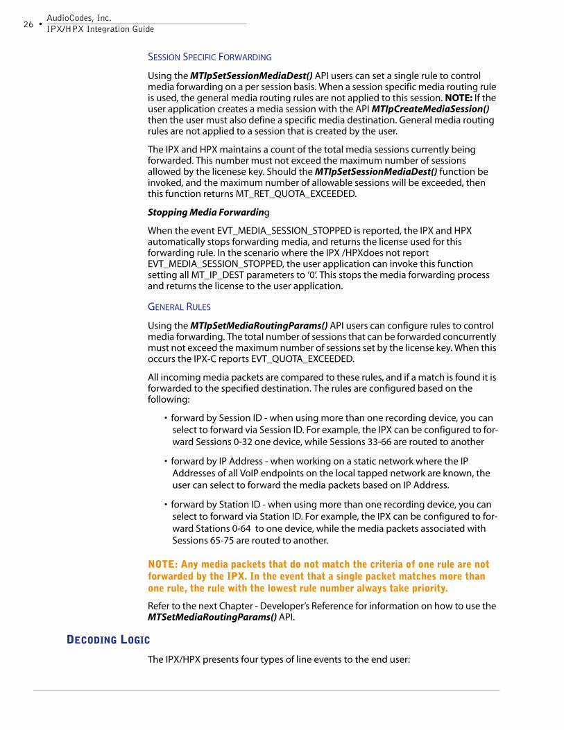
SESSION SPECIFIC FORWARDING
Using the MTIpSetSessionMediaDest() API users can set a single rule to control media forwarding on a per session basis. When a session specific media routing rule is used, the general media routing rules are not applied to this session. NOTE: If the user application creates a media session with the API MTIpCreateMediaSession() then the user must also define a specific media destination. General media routing rules are not applied to a session that is created by the user.
The IPX and HPX maintains a count of the total media sessions currently being forwarded. This number must not exceed the maximum number of sessions allowed by the licenese key. Should the MTIpSetSessionMediaDest() function be invoked, and the maximum number of allowable sessions will be exceeded, then this function returns MT_RET_QUOTA_EXCEEDED.
Stopping Media Forwarding
When the event EVT_MEDIA_SESSION_STOPPED is reported, the IPX and HPX automatically stops forwarding media, and returns the license used for this forwarding rule. In the scenario where the IPX /HPXdoes not report EVT_MEDIA_SESSION_STOPPED, the user application can invoke this function setting all MT_IP_DEST parameters to ‘0’. This stops the media forwarding process and returns the license to the user application.
GENERAL RULES
Using the MTIpSetMediaRoutingParams() API users can configure rules to control media forwarding. The total number of sessions that can be forwarded concurrently must not exceed the maximum number of sessions set by the license key. When this occurs the IPX-C reports EVT_QUOTA_EXCEEDED.
All incoming media packets are compared to these rules, and if a match is found it is forwarded to the specified destination. The rules are configured based on the following:
• forward by Session ID - when using more than one recording device, you can select to forward via Session ID. For example, the IPX can be configured to for-ward Sessions 0-32 one device, while Sessions 33-66 are routed to another
• forward by IP Address - when working on a static network where the IP Addresses of all VoIP endpoints on the local tapped network are known, the user can select to forward the media packets based on IP Address.
• forward by Station ID - when using more than one recording device, you can select to forward via Station ID. For example, the IPX can be configured to for-ward Stations 0-64 to one device, while the media packets associated with Sessions 65-75 are routed to another.
NOTE: Any media packets that do not match the criteria of one rule are not forwarded by the IPX. In the event that a single packet matches more than one rule, the rule with the lowest rule number always take priority.
Refer to the next Chapter - Developer’s Reference for information on how to use the MTSetMediaRoutingParams() API.
DECODING LOGIC
The IPX/HPX presents four types of line events to the end user:
IPX OverviewBoard Features
• 27
• D-channel - signaling and terminal control messages are decoded and passed to the end user
• Call Control Events - an underlying call state machine abstracts information and provides call state event reporting
• Media Events - all media (RTP) connections are monitored and reported to the end user
• Station Events - alerts the application when VoIP endpoints are added or removed from the monitored network
NOTE: Protocol ID and Station ID are presented in the XtraInfo field of the MT_EVENT structure with all IPX events. This field contains four(4) bytes of data - two bytes for protocol ID and two bytes for station ID.protocol ID = (Event.XtraInfo & 0xFFFF0000) >> 16station ID = Event.XtraInfo & 0x0000FFFF
D-CHANNEL EVENTS
The IPX and HPX provides D-Channel decoding similar to the D-Channel decoding on the NGX. To obtain D-channel information the tap must be positioned between the local VoIP phones and the IP-PBX (VoIP Call Agent). The user application must enable the protocol decoding stack on the board, and then enable D-channel event reporting for this protocol.
The D-Channel decoder provides a message-to-event translation for the terminal control messages. AudioCodes groups all D-channel events into two types:
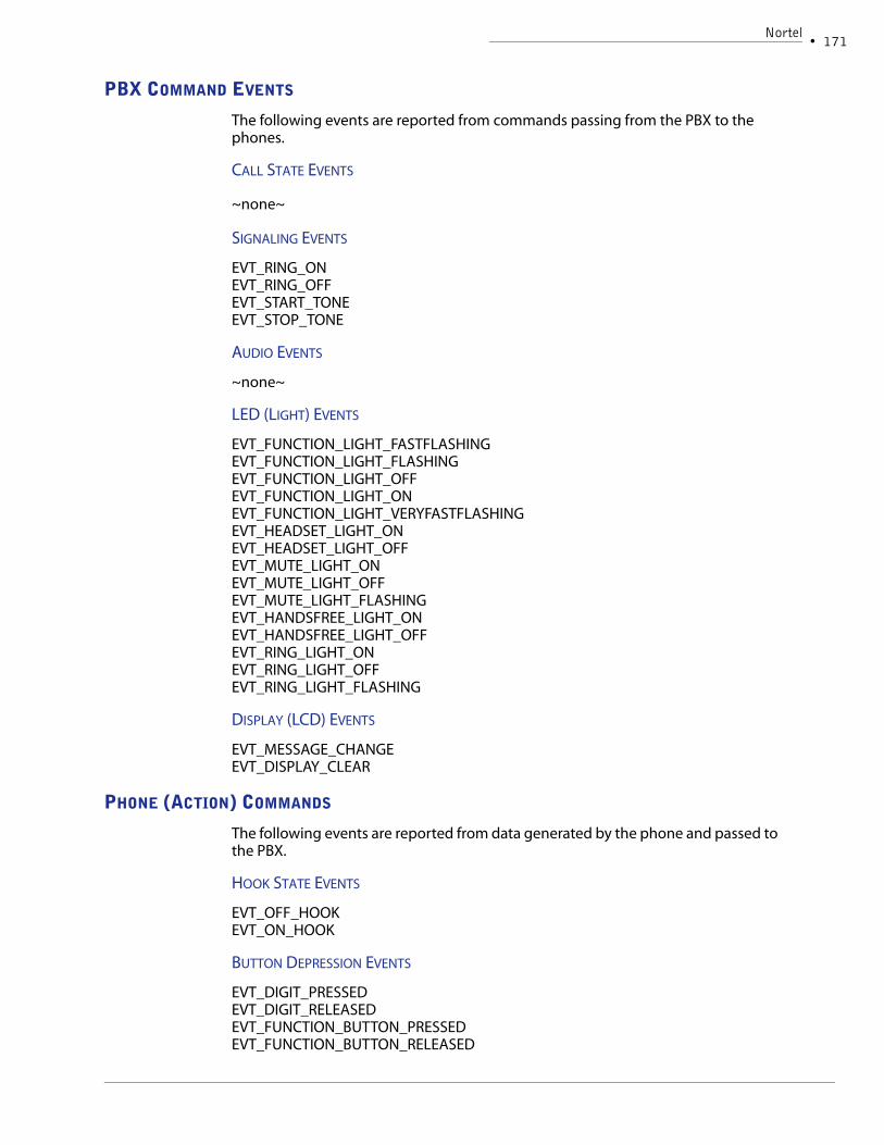
• PBX Command events - messages initiated by the PBX to control the phone
• Phone Action Events - messages initiated by the phone to inform the PBX of an action taken
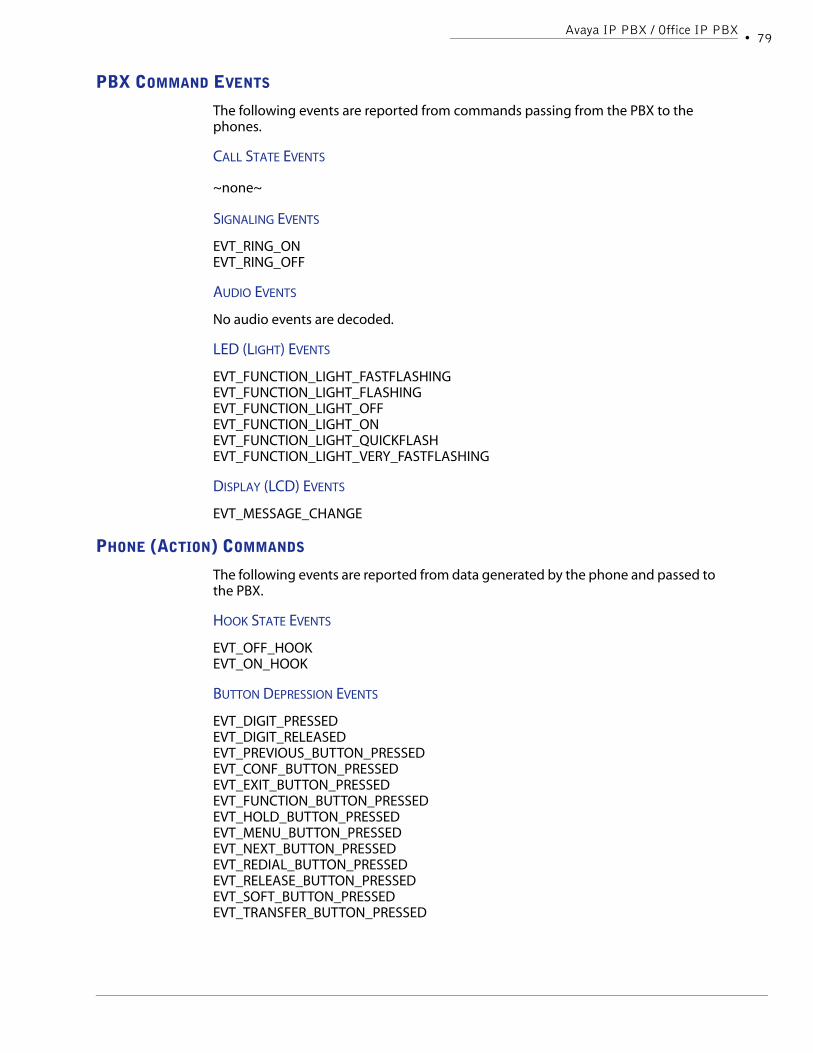
PBX COMMAND EVENTS
The following types of command events are reported to the user application:
• Signaling - these events indicate the PBX is commanding the phone to pro-duce a tone (ringing, or incoming page)
• Audio Events - indicate the PBX is controlling external audio devices such as headsets or microphones
• LEDs - these events correspond to light changes on the phone. Light events are important indications when monitoring call states and feature activity.
• Display - these events indicate that the LCD on the phone has been updated. These are usually related to the clock display, or messages displayed on the LCD.
• Call State - these events are generated with a change in call state (NOTE: These are not related to Call Control events).
28 •AudioCodes, Inc.IPX/HPX Integration Guide
PHONE ACTION EVENTS
These events are generated by the phone after an action has been taken (i.e. button pressed). The phone is informing the PBX that something has occurred. Events generated by the phone have been classified by the following types:
• Hook State - off hook and on hook changes occur when the handset is removed or replaced
• Button Depression events - indicate that a button on the phone was used. For example: digits, speaker buttons etc. Button events can include both a pressed or released event, depending on the PBX.
By default, D-channel event reporting must be enabled. Users control this feature with the MTIpDChannelEventControl() API. It is important to understand that the exact D-channel events reported by the IPX and HPX vary per protocol., PBX model and software model, as well as the specific phone models on the network. This document contains chapters per each protocol describing the specific D-channel events supported.
CALL CONTROL EVENTS
When possible, a call state machine has been developed for each VoIP protocol. The call state machine abstracts the underlying protocol to present a consistent interface via common events to the user application. The user application must enable the protocol stack on the board in order to receive call control events. By default, call control events are not presented to the user application and must be enabled via the MTIpCCEventControl() API.
The following call control events are supported by the IPX and HPX:
As each event is reported the Protocol ID and Station ID is passed to the user application via the XtraInfo field of the MT_EVENT structure. This field contains four(4) bytes of data - two bytes for protcol ID and two bytes for station ID.protocol ID = (Event.XtraInfo & 0xFFFF0000) >> 16station ID = Event.XtraInfo & 0x0000FFFF
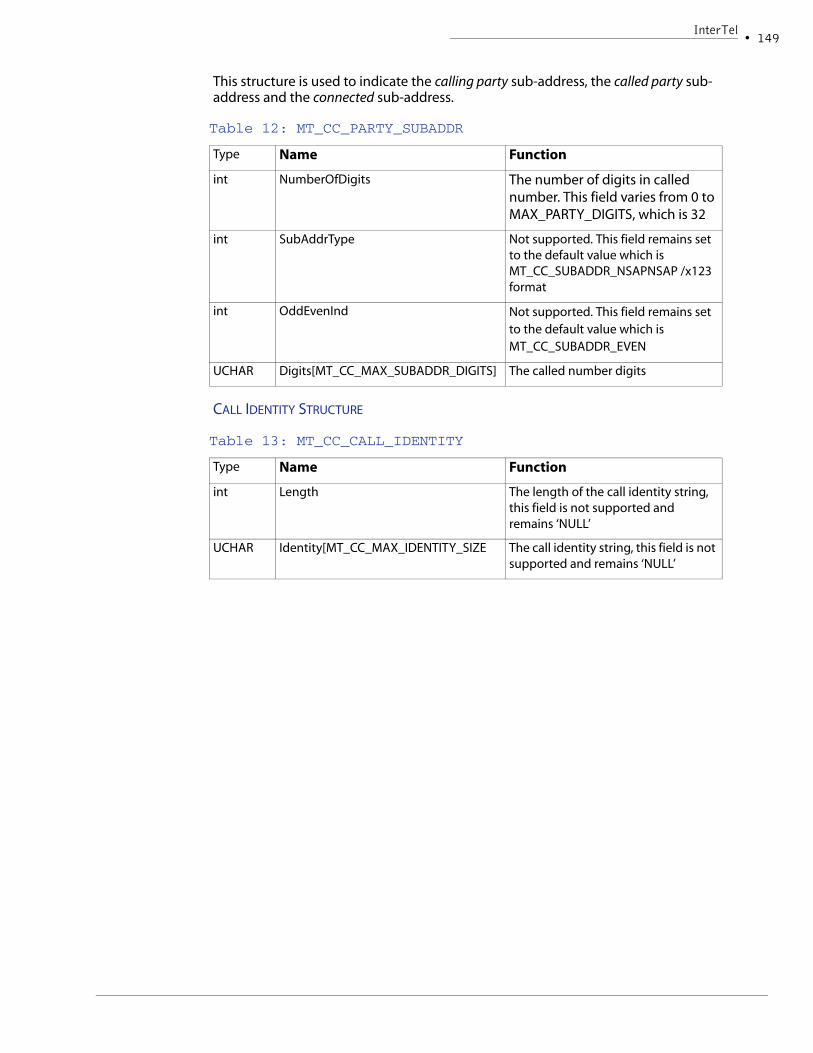
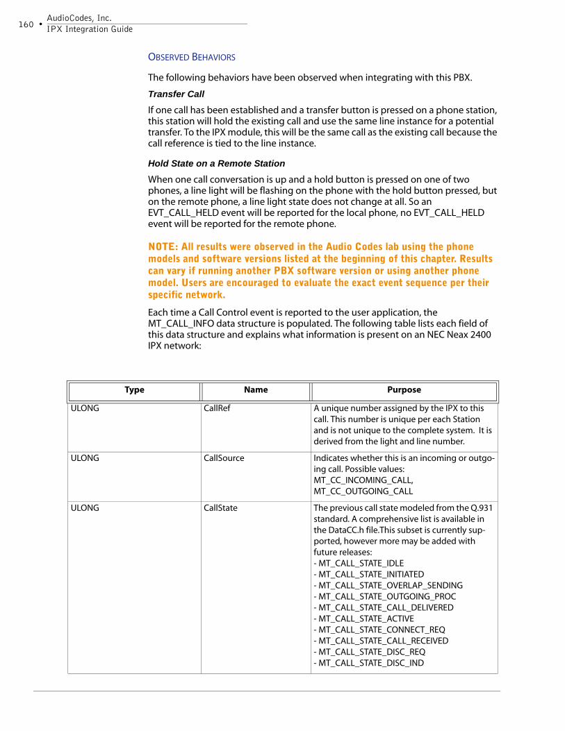
Another event structure, MT_CALL_INFO is also passed to the user application containing call details.
MEDIA SESSION EVENTS
The IPX/HPX Session Manager handles the monitoring of media connections on the network. This was previously explained in the section: Session Manager Logic.
STATION EVENTS
The IPX/HPX Station Manager monitors VoIP endpoints on the network. This process was previously explained in the section: Station Manager Logic.
IPX OverviewBoard Features
• 29
MISCELLANEOUS NETWORK INFORMATION
Though the signaling protocol varies from network to network, most call logging applications need to obtain the same information. This section discusses how the IPX and HPX can be used to retrieve CallerID, DTMF or digit pressed events.
CALLER ID
When using the IPX or HPX, CallerID can be obtained in various ways. How the application developer wishes to proceed is determined by the network protocol, tap location and use of the board.
CallerID can be passed to the user application via one of the following methods:
• Call Control Events - these events are only generated if call control event reporting is enabled via the MTIpCCEventControl() API. When a call control event is reported, the called and calling party number is passed to the user application via the MT_CALL_INFO structure. The following call control events rely on the MT_CALL_INFO structure:EVT_CC_CALL_ALERTINGEVT_CC_CALL_ABANDONEDEVT_CC_CALL_CONNECTEDEVT_CC_CALL_HELDEVT_CC_CALL_REJECTEDEVT_CC_CALL_RELEASEDEVT_CC_CALL_RESUMEDEVT_CC_CALL_RETRIEVEDEVT_CC_CALL_SUSPENDED
• In the event that call control event reporting is not supported, the user appli-cation can rely on EVT_MESSAGE_CHANGE when Caller ID is displayed on the phone’s LCD. Once the phone’s LCD is updated the EVT_MESSAGE_CHANGE event is reported and the CallerID is passed to the user in ASCII format via the event’s buffer.
• When the SmartWORKS event EVT_MEDIA_SESSION_STARTED is reported, an event structure is populated with the primary and secondary IP Addresses. If the user application is monitoring a network where agent phones have static IP addresses, then this method can be used to map the extension number to media session.
DTMF DETECTION
Some VoIP protocols support in-band DTMF transmission, while others transmit DTMF information digitally. The IPX or HPX does not have detectors to support in-band DTMF detection. As a result, only networks which rely on digital signals to relay DTMF information can be decoded by the boards.
DIGITS PRESSED
When a local agent presses a digit on the phone, this action is normally passed back via signaling channels to the IP PBX. The IPX and HPX decodes these instructions and reports an EVT_DIGIT_PRESSED event. The subreason field passes over the exact digit that was pressed.
30 •AudioCodes, Inc.IPX/HPX Integration Guide
Chapter 4Developer’s Reference
32 •AudioCodes, Inc.IPX/HPX Integration Guide
IntroductionThis section is written as a quick reference guide for application development on both the IPX and HPX products and does not contain a comprehensive explanation of the SmartWORKS API. For details on each API refer to the SmartWORKS Function Reference Library. The following section provides a quick introduction to SmartWORKS API for configuration and control of the IPX/HPX. This section has been provided to application developers who are:
• migrating existing PSTN applications designed with the SmartWORKS API onto the IPX/HPX
• new to SmartWORKS and requesting a quick “tour” of the IPX/HPX application environment.
This chapter is organized in the following sections:
SmartWORKS and the IPX/HPX
Provides an overview of the SmartWORKS API and variations which should be noted before programming with IPX components; and any differences noticed when programming with the HPX. This section also provides a comprehensive list of all SmartWORKS APIs supported by the IPX/HPX.
The IPX/HPX API
Explains which APIs are required to configure and control the IPX and HPX boards. The following topics are discussed: configuration, packet filtering, Station Manager, Media (RTP) Forwarding, D-channel decoding, and Call Control.
SmartWORKSThis section provides a logical understanding of using the SmartWORKS API with IPX and HPX boards. This section is especially useful to application developers who are migrating existing SmartWORKS based PSTN applications to the VoIP environment.
UPDATING THE FIRMWARE
The SmartWF utility used to update the IPX board’s firmware. The HPX product is a software only solution and no firmware is required.
NOTE: Due to the firmware changes associated with the 3.9 release, once an IPX board has been installed on a system running SmartWORKS 3.9, this board can no longer be installed on a system running version 3.8 or earlier.
UPDATING THE LICENSE KEY
The IPX and HPX boards are licensed differently. Carefully read the following section to learn about the two unique license strategies.
IPX LICENSE FILE
The IPX license file limits the number of media sessions that are forwarded from the board to recording resources. This file does not limit the number of endpoints that can be monitored. For example, if a 20 session license file is purchased, and 100
Developer’s Reference• 33
phones are visible to the IPX, call control events are reported for all 100 phones. The user application has the ability to forward no more than 20 concurrent media sessions.
All IPX boards, by default, forward a maximum of 8 media sessions - each media session equates to a full-duplex conversation. License keys can be purchased, to allow the IPX to forward more concurrent media sessions.
To update or add a license file to the IPX, users can log into the board’s web server by pointing a browser to the IP address of the active port; or rely on the SmartWORKS API. The license file can also be updated using SmartVIEW.
The default user and password are both admin (case sensitive). Once logged in, users can navigate to the Administration page to change the password. Remember the user name and password are both case sensitive.
To add or update an IPX license, navigate to the License page. The following screen is displayed:
A license file (.dat format) has been emailed to you. Simply save this file to any folder on the computer that has access to the IPX via a browser. Use the Browse button to nagivate to this license file and then use the Send button. When finished, the new license key information is displayed on this page. The Max Sessions field indicates the total number of media sessions that can be forwarded from this IPX board.
NOTE: Each license key is generated specifically for an individual IPX board based on it’s serial number. The same license key cannot be used by multiple IPX boards.
To purchase additional license keys, contact your AudioCodes sales representative.
HPX LICENSE FILE
The HPX software product also requires a license file; however this file controls more than just media forwarding. The HPX license is purchased with a single session value; however this value limits monitoring capabilities as well as media forwarding. The HPX license also comes with corresponding Soft Recorder license. For every session purchased for use by the HPX, the same number of recording sessions is also available for the Soft Recorder.
34 •AudioCodes, Inc.IPX/HPX Integration Guide
Monitoring limits: The HPX license limits the ability to receive call control events. The HPX reports all call control information until the license number has been met for the total number of concurrently active endpoints.
This same license limit is used to limit the forwarding of media sessions. For example; an HPX is purchased with a license of 60. This HPX is installed on a network with 100 endpoints total. As calls come into the call center, the HPX will begin reporting events for each endpoint. The user application has the ability to forware media for each endpoint. The HPX will continue reporting call control events up to the 60th endpoint. Any phone that goes off hook after this limit has been met, will not be reported to the application by the HPX.
SDK SUPPORT
The IPX is only compatible with the SmartWORKS version 3.6 or greater. Other SmartWORKS SDKs will not work with the IPX.
The HPX is only compatible with the SmartwWORKS version 5.0 or greater. Other SmartWORKS SDKs will not work with the HPX.
GLOBAL CHANNEL INDEX
Legacy SmartWORKS boards are designed for traditional PSTN systems where a channel is a physical element on each network. During initialization, as the Physical Boards are numbered, the driver builds a list of the logical channels available in the system. VoIP networks do not rely on physical channels - therefore the SmartWORKS SDK does not build this list for either the IPX and HPX.
The IPX/HPX is designed with a Station Manager and a Session Manager. The primary role of the Station Manager is to identify station endpoints. Each VoIP endpoint is assigned a unique Station ID. As signaling data is passed to/from the station endpoint, this data is decoded and reported to the user application - along with the Station ID.
The Session Manager monitors all media connections on the network. When a media connection is established a Session ID is reported to the user application along with the Station ID associated with this media connection. With this information, Station ID and Session ID, applications control the forwarding of voice data on the VoIP network to a voice recording apparatus on the network.
The Global Channel Index used by your application will not be altered with the installation of an IPX or HPX board.
DSP RESOURCES
The IPX/HPX do not have any DSP resources. This board is not designed for signal detection or recording purposes. The IPX and HPX has been designed with packet forwarding capabilities which enable the user to forward media packets to another system on the network for signal processing and recording.
MANAGING EVENTS
With SmartWORKS products designed for the PSTN environment, all D-channel events are reported as channel events. Since the IPX and HPX do not map channels, only board and system events are reported. Each event is reported with a Station ID that identifies the station equipment that is transmitting or receiving the message. The Station ID is presented in the XtraInfo field of the MT_EVENT structure, along with the Protocol ID representing the protocol used by this VoIP endpoint. This field
Developer’s Reference• 35
contains four(4) bytes of data - two bytes for protocol ID and two bytes for station.protocol ID = (Event.XtraInfo & 0xFFFF0000) >> 16station ID = Event.XtraInfo & 0x0000FFFF
The user application is responsible for servicing the queue often enough to ensure that it does not overflow. If the event queue is full, new events are lost and are reported in the Windows Event Viewer. NOTE: When using Linux, all information is written to a ‘messages’ file located in the /var/log directory.
MT_EVENT
The MT_EVENT structure is used to retrieve event information generated by the board. Users have two options for retrieving event information: polling method or callback method. When polling, data is retrieved from the event queue with MTGetBoardEvent() or MTWaitForBoardEvent(). Another method is to rely on the call back method to populate the MT_EVENT structure. Both of these methods are discussed in detail in the SmartWORKS Developer’s Guide.
36 •AudioCodes, Inc.IPX/HPX Integration Guide
This structure is declared in NtiEvent.h. The following table lists each field of the MT_EVENT structure relative for use with the IPX and HPX boards.
TABLE 1: MT_EVENT
Type Name Function
LARGE_INTEGER(WIN3
2)
timeval (Linux)
TimeStamp Time stamp when the event occurred. In FILETIME format
ULONG UserStatus User defined value
ULONG EventCode The event code
ULONG SubReason Extended event information
ULONG XtraInfo Protocol ID / Station ID This field contains four(4) bytes of data - two bytes for protocol ID and station ID.
protocol ID = (Event.XtraInfo & 0xFFFF0000) >> 16
station ID = Event.XtraInfo & 0x0000FFFF
ULONG FuncCode The function that generated this event. ~not used on the IPX~
ULONG Board Board the event occurred on
ULONG Channel ~not used on the IPX~
PVOID PtrBuffer Pointer to event associated buffer, if any
ULONG DataLength Size of exercised data of the associated buffer, if any
PVOID ptrXtraBuffer* pointer to buffer containing extra information*
ULONG XtraBufferLength* Length of ptrXBuffer*
ULONG XtraDataLength* Length of data put into the prtXtraBuffer by the DLL. *
Developer’s Reference• 37
* These fields are only used for call control events.
EVENTS SUPPORTED BY THE IPX AND HPX
A comprehensive list of all events supported by the SmartWORKS SDK is available in the SmartWORKS Function Reference Library. The table below lists all SmartWORKS events available on the IPX and HPX. This table does not include D-channel or Call Control events. The types of D-channel and Call Control events vary per VoIP protocol and are presented in the corresponding chapter associated with each PBX supported.
ULONG EventFlag Flag for XtraBuffer information:
Bit 0X00000001 1- Appl. created this event 0 - DLL created this event
Bit 0x00000002:
1 - Appl. allocated the buffer
0 - DLL allocated the buffer
Bit 0x000000004
1 - data has been truncated
0 - data has not been truncated
TABLE 1: MT_EVENT (CONTINUED)
Type Name Function
Board Hex Dec Event Description
All 0x04 4 EVT_SYS_ERROR System response error
All 0x06 6 EVT_ERROR Hardware failure
All 0x10 16 EVT_BOARD_PANIC_ERROR Board Panic error
All 0x51 81 EVT_NOT_AVAILABLE Functionality not available or busy
All 0x52 82 EVT_NOT_SUPPORTED Functionality not supported
All 0x53 83 EVT_NO_EFFECT Functionality not necessary (already done)
All 0xC8 200 EVT_SYS_SYNCTIME_OLD resync time
All 0xC9 201 EVT_SYS_SYNCTIME_NEW resync time
All 0xCA
202 EVT_SYS_BOARD_ADDED new board added to system
All 0xCB
203 EVT_SYS_BOARD_REMOVED -not implemented yet-
EVT_MEDIA_SESSION_STARTED - New event
EVT_MEDIA_SESSION_STOPPED - New event
EVT_STATION_ADDED - New event
38 •AudioCodes, Inc.IPX/HPX Integration Guide
IPX AND HPX APIS
All SmartWORKS APIs supported by the IPX and HPX are Immediate functions. An immediate API function is one that does not return until it is completed. This is also referred to as a synchronous function. Since voice processing capabilities are not performed by these boards, no background functions are supported on this board.
All APIs are defined in the SmartWORKS Function Reference Library.
The IPX/HPX APIThe following section explains how to use the SmartWORKS API to configure and control the IPX and HPX boards.
BOARD CONFIGURATION - IPX
The IPX has three ethernet interfaces. Devices 1and 2 are configured in promiscuous mode and receive all packets from the tapped line. On a typical application one link receives downstream packets while the other receives upstream packets (Relative to the tapped station).The third device (port 0) is active and is used to transmit media (RTP) media packets to a recording device.
This section outlines the IPX’s APIs used for board and device configuration.
IMPORTANT INSTALLATION NOTE
While installing the IPX for development purposes or testing, users may not install the tap point (the TX100) between two switches. While using this product in a lab, developers may choose to connect a phone directly to the TX100. AudioCodes has observed that some IP phones to not terminate the signal, and rely on terminating network devices, such as a switch. When a non-terminating phone is connected directly to the TX100, the signaling information passing from the TX100 to the IPX is not correct. The AudioCodes lab has noticed, that the Dchannel path from the PBX to the phone is broken, and these type of events are not reported by the IPX. Should users experience this type of problem while tapping with the IPX, they should change their network configuration and position the TX100 between two terminating devices - such as two switches.
BOARD CONFIGURATION
The IPX does have an H.100 interface, but it is not enabled for use. When configuring the IPX clock termination is not required.
Most SmartWORKS system and board APIs are supported by the IPX. Refer to the comprehensive list of APIs supported by the IPX for details. Two APIs MTSet/GetAdaptorConfig() have been modified to support the IPX.
PORT CONFIGURATION
The MT_ADAPTERCONFIG structure has been modified to include a pointer to an array of three data structures (MT_IPCONFIG) for purposes of configuring the three Ethernet links. Users must supply IP addresses, subnet mask, and the default Gateway for the active device (port 0). Devices 1 and 2 have system default settings that enable them to work if the user does not provide information.
EVT_STATION_REMOVED - New event
Board Hex Dec Event Description
Developer’s Reference• 39
NOTE: It is important that the passive monitoring ports and the active media forwarding port are configured for different networks to avoid conflicts within the routing table.
When setting the default gateway tha t is used by the IPX, it is important to use a gateway that is visible to the port used for transmitting media packets.
The IPX also supports DHCP. This feature can be enabled on a port by port basis. Domain Name Server (DNS) support has been added in that the IPX can be directed to point to a DNS server.
All of the above configuration can be accomplished with the API MTSetAdapterConfig() or via the SmartWORKS Control Panel.
BOARD CONFIGURATION - HPX
The HPX software is automatically installed with the SmartWORKS SDK. The SmartWORKS SDK will not recognize the HPX board unless the hardware key has been installed into the USB port of the server running the SDK. Once the hardware key is installed, the SDK will then recognize the board. This board runs at default level of 8 sessions. To increase product density, a license file must be purchased from AudioCodes and installed onto the system using the SmartWORKS API or via the Control Panel.
Once the HPX is fully operational, the user must then configure the ports which must be monitored for packets. Using the Control Panel, the user may select up to two NIC cards for receiving VoIP packets and monitoring.
NOTE: The same NIC card should not be used for monitoring VoIP packets and forwarding RTP to the media server.
PROTOCOL CONFIGURATION
The IPX or HPX is designed to decode multiple protocols at a single time. Users must enable each protocol decoding stack that will be running. Three APIs have been added to control signaling protocol stacks; MTIpEnableSignalingProtocol(), MTIpDisableSignalingProtocol(), and MTIpSignalingProtocolStatus(). When enabling a signaling protocol, users are required to provide PBX specific parameters. Refer to the individual PBX chapters in this guide for configuration instructions.
NOTE: Parameters cannot be modified without disabling the protocol first.
SIGNALING STATISTICS
Users can rely on the API MTIpGetSignalingStatistics() to retrieve data collected for a specified protocol. The information returned is protocol specific so the application must provide the correct protocol dependant statistics structure. Use the MTIpClearSignalingStatistics() API to clear or reset the statistics collected by the board. NOTE: These APIs are not supported in the Beta release but will be supported in future releases.
40 •AudioCodes, Inc.IPX/HPX Integration Guide
PACKET FILTERING
All ethernet data from the tapped line is forwarded to the IPX and HPX. The IPX or HPX sorts through the packets and discards data that is not relevant to a VoIP tapping application. All signalling traffic is passed within the board to the appropriate decoding stack, while all media packets (RTP traffic) are forwarded to the Session Manager.
This capability of IPX and HPX products is not programmable. No configuration is required by the user application.
NOTE: The IPX and HPX can be configured to only process packets from a specific VLAN. Use the SmartWORKS Control Panel or the MTSetAdapterConfig() to enable this feature.
STATION MANAGER
The IPX/HPX identifies VoIP endpoints on the network transmitting or receiving VoIP related packets. As a station is discovered a unique Station ID is reported to the user application. The EVT_STATION_ADDED event is generated with the Protocol ID and Station ID in the XtraInfo field of the MT_EVENT structure. This field contains four(4) bytes of data - two bytes for protocol ID and two bytes for station ID.protocol ID = (Event.XtraInfo & 0xFFFF0000) >> 16station ID = Event.XtraInfo & 0x0000FFFF
To obtain more information about each phone (such as IP Address and port numbers of the phone) users must invoke the function MTIpGetStationParams().
When a station is no longer transmitting on the tapped line for a specified period of time, the EVT_STATION_REMOVED event is reported.
The IPX/HPX board generates unique numbers for each active station. When operating a system running multiple boards it is possible to obtain the same Station ID on one system, though the matching Station IDs are generated from separate boards. Developers are encouraged to design a Station manager within their applications to monitor active station endpoints.
Rules:
• Station IDs are dynamic values and change as VoIP endpoints are added or removed from the network. When a station is no longer transmitting on the network it is reported as inactive (EVT_STATION_REMOVED) and the Station ID is returned to IPX/HPX for reuse.
• When two or more IPX boards are used on a single network each board assigns Station IDs independently of one another. As a result, the same phone ID may be passed multiple times to a single application since the information is generated by different boards. It is also true that two boards may identify the same device. Thus a single VoIP endpoint may be assigned different Sta-tion IDs from multiple boards.
PROTOCOL DIFFERENCES
The IPX/HPX reports EVT_STATION_REMOVED when a media station is no longer detected on the network. Due to differences in protocol behavior, the IPX or HPX is unable to report that a station has been removed at the same time across all protocols. The application developer must understand that the EVT_STATION_REMOVED events may occur 5 minutes or 24 hours after the actual
Developer’s Reference• 41
phone was removed from the network. Developers are encouraged to read the protocol specific chapter to learn how this feature works on the environment they are tapping.
OBTAINING PHONE’S EXTENSION NUMBERS
When available in signaling messages on the tapped line, the IPX and HPX can obtain the phone’s extension number. This information is passed to the user application via the Caller and Called Number fields of the MT_CALL_INFO data structure associated with call control events. A function MTGetExtension() has also been implemented that allows the user application to query the phone’s extension number for specific line instances. This function is supported with Avaya and Cisco integrations. For more information refer to the protocol specific chapter.
MANAGING STATIONS WITH SMARTWORKS APIS
The following APIs have been added to the SmartWORKS API to manage stations on the tapped network. Each API is defined in detail at the end of this chapter.
MTIpGetStationCount() - returns a count of active stations on the network that the board is aware of.
MTIpGetStationList() - returns a list of all active stations on the network. Provides Protocol ID / Station ID for each active station on the monitored network.
MTIpGetStationParams() - returns a protocol specific data structure containing information of the specified VoIP endpoint.
MTIpGetStationStatistics() - provides protocol specific statistics for a specified station. This API is not supported in the Beta release but will be supported in future releases.
MTIpClearStationStatistics() - clears or resets station statistics for a specified station
MEDIA SESSION MANAGER
IPX and HPX boards are designed with a Session Manager. When a media session (RTP connection) is established, the EVT_MEDIA_SESSION_STARTED is reported to the user application. This event passes data into an event structure MT_IP_SESSION_PARAMS which provides the following information:
NOTE: This data structure has been modified as of the 3.9 release..
Type Name Description
ULONG SessionID The Session ID associated with this RTP media connection
USHORT PrimaryUDPPort The UDP port used by the phone(on the tapped network) to receive RTP packets *
USHORT SecondaryUDPPort The UDP port used by the VoIP endpoint (not on the tapped network to receive RTP packets*
ULONG PrimaryIPAddress The IP address of the phone on the tapped net-work*
ULONG SecondaryIPAddress The IP address of the VoIP endpoint that is not on the tapped network*
42 •AudioCodes, Inc.IPX/HPX Integration Guide
*When a media session is established between two phones on the tapped network the Primary IP Address and UDP port are associated to the phone that is the first to establish the media session (the XtraInfo field displays the StationID). This is reported with th e EVT_MEDIA_SESSION_STARTED event.
When a Session ID is active, users are able to invoke an API to obtain the same call information:
MTIpGetMediaSessionInfo() - retrieves information about an established media session on the tapped network. Provides IP addresses and UDP ports of both VoIP endpoints connected in this call.
Developer’s Notes
Some VoIP networks (i.e. Avaya) pass call progress tones such as dial tones and busy signals over the network via RTP. As a result, the event EVT_MEDIA_SESSION_STARTED is reported when a connection is established between the station endpoint and the Avaya media server. On Cisco networks, an RTP connection is required between endpoints and the Call Manager when “hold music” is played.
MULTIPLE PHONES ON A SINGLE TAP
In the event that two monitored endpoints are joined in the same conversation (peer-to-peer or agent-to-agent call) then the IPX reports two media session events. EVT_MEDIA_SESSION_STARTED is reported on the first endpoint that established a media session. The second event EVT_AUX_MEDIA_SESSION_STARTED is reported for the second station. The same SessionID is reported with both events.
CREATING A MEDIA SESSION
Your application can rely on other means to monitor RTP sessions established on the network, such as a CTI link. The application can then invoke an API to create a Media Session by providing primary and secondary IP addresses and UDP ports. The IPX or HPX then returns a Session ID to the user application which uses the ID to control media forwarding. The following APIs are used to create and delete media sessions on the IPX/HPX products:
union {
ULONG Codec Codec of the RTP packets. This field is used for backward compability, being obsoleted
ULONG PrimaryCodec Codec used by the primary station when trans-mitting RTP.
} (end union)
ULONG SecondaryCodec Codec used by the secondary station when transmitting RTP.
ULONG CallRef This field is only populated when using the IPX for SIP trunk recording. This value is a call refer-ence number maintained by the IPX to identify the call on the network.
Type Name Description
Developer’s Reference• 43
MTIpCreateMediaSession() - invoke this API to create a media session by supplying IP addresses and UDP ports for both VoIP endpoints.
MTIpDeleteMediaSession() - returns the Media Session ID to the IPX./HPX
NOTE: When a media session is created by a user application, none of the general media routing rules apply. Users must set a specific media routing destination using MTIpSetSessionMediaDest().
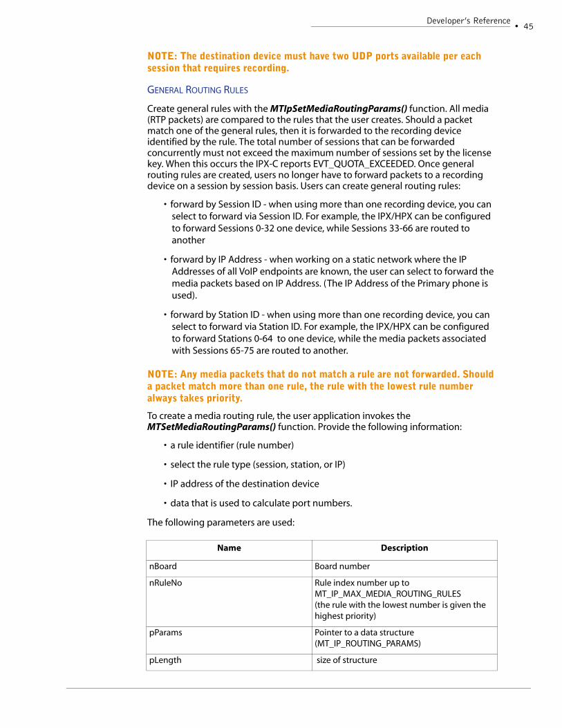
MEDIA (RTP) FORWARDING
The IPX and HPX are both designed with media forwarding capabilities. Currently, the product only forwards media packets to a network destination. The number of media sessions that are forwarded from the product are limited by a license key. By default, the IPX and HPX boards will forward eight (8) full duplex conversations (sessions). To forward more the user must purchase extra license resources.
The IPX and HPX will not forward any media packets from the board. The user must configure these settings. Two options are available - general rules using the MTIpSetMediaRoutingParams() API, and session specific rules using the MTIpSetSessionMediaDest() API.
Developer’s Note
Once the IPX/HPX begins forwarding media, all packets are automatically passed off the board until the EVT_MEDIA_SESSION_STOPPED event is reported. This event indicates that the media session has been disconnected. When using call control events to trigger stop recording, the application should also wait for a corresponding session stopped event before closing therecording channel.
Stopping Media Forwarding
When the event EVT_MEDIA_SESSION_STOPPED is reported, the IPX/HPX automatically stops forwarding media, and returns the license used for this forwarding rule. In the scenario where the IPX/HPX does not report EVT_MEDIA_SESSION_STOPPED, the user application can invoke the function that sets the forwarding destination and set all MT_IP_DEST parameters to ‘0’. This stops the media forwarding process and returns the license to the user application.
SESSION SPECIFIC RULES
To create a Session Specific rule invoke MTIpSetSessionMediaDest(). This rule only applies while the specified session is active. Once the session is disconnected, then this rule no longer applies. The IPX and HPX maintains a count of the total number of media sessions it is currently forwarding. Should this function be invoked when the number of forwarded sessions matches the maximum allowed by the license
44 •AudioCodes, Inc.IPX/HPX Integration Guide
key then this function returns MT_RET_QUOTA_EXCEEDED. NOTE: This rule overrides all general rules. The data structure MT_IP_SESSION_DEST is used to configure the destination parameters for the specified session:
NOTE: If a session is created using MTpCreateMediaSession() all general rules do not apply for this session. The user must also set a session specific routing rule or these packets will not be forwarded to a recording destination.
Developer’s Note
To convert the dotted quad IP Address to a ULONG the following bit of code can b e used:
int exIPAddr2int(const char *IPaddr){int ip1, ip2, ip3, ip4;sscanf(IPaddr,"%d.%d.%d.%d",&ip1,&ip2,&ip3,&ip4);return ( (ip1)<<24|(ip2)<<16|(ip3)<<8|(ip4));}
Port Numbering
When the MTIpSetSessionMediaDest() is used, the recording device can control the port numbering scheme or the user application can control this on both boards. The MT_IP_SESSION_DEST structure identifies the exact ports upstream and downstream packets should be transmitted to.
When the destination board controls port numbering: the board resources assign a port number when a channel is opened to receive incoming UDP packets. This number must then be passed over to the IPX and HPX when setting the destination information using the MTSetSessionMediaDest() API.
When the application controls port numbering: The user application can set port numbering when the channel is opened on the recording device and then apply these numbers to the forwarding rule using the MTSetSessionMediaDest() API.
Name Description
fTarget Flag indicating the destination target type. May be one of the following: NETWORK | HOST (future releases)
DestPrimaryStationIPAddr The IP address of the recording device that receives media packets that the primary sta-tion is transmitting.
DestSecondaryStationIPAddr The IP address of the recording device that receives media packets that the secondary sta-tion is transmitting.
DestPrimaryStationBaseID When fTarget = NETWORK - the port on the recording device where packets associated with the primary station are sent.
DestSecondaryStationBaseID When fTarget = NETWORK - the port on the recording device where packets associated with the secondary station are sent.
Developer’s Reference• 45
NOTE: The destination device must have two UDP ports available per each session that requires recording.
GENERAL ROUTING RULES
Create general rules with the MTIpSetMediaRoutingParams() function. All media (RTP packets) are compared to the rules that the user creates. Should a packet match one of the general rules, then it is forwarded to the recording device identified by the rule. The total number of sessions that can be forwarded concurrently must not exceed the maximum number of sessions set by the license key. When this occurs the IPX-C reports EVT_QUOTA_EXCEEDED. Once general routing rules are created, users no longer have to forward packets to a recording device on a session by session basis. Users can create general routing rules:
• forward by Session ID - when using more than one recording device, you can select to forward via Session ID. For example, the IPX/HPX can be configured to forward Sessions 0-32 one device, while Sessions 33-66 are routed to another
• forward by IP Address - when working on a static network where the IP Addresses of all VoIP endpoints are known, the user can select to forward the media packets based on IP Address. (The IP Address of the Primary phone is used).
• forward by Station ID - when using more than one recording device, you can select to forward via Station ID. For example, the IPX/HPX can be configured to forward Stations 0-64 to one device, while the media packets associated with Sessions 65-75 are routed to another.
NOTE: Any media packets that do not match a rule are not forwarded. Should a packet match more than one rule, the rule with the lowest rule number always takes priority.
To create a media routing rule, the user application invokes the MTSetMediaRoutingParams() function. Provide the following information:
• a rule identifier (rule number)
• select the rule type (session, station, or IP)
• IP address of the destination device
• data that is used to calculate port numbers.
The following parameters are used:
Name Description
nBoard Board number
nRuleNo Rule index number up to MT_IP_MAX_MEDIA_ROUTING_RULES (the rule with the lowest number is given the highest priority)
pParams Pointer to a data structure (MT_IP_ROUTING_PARAMS)
pLength size of structure
46 •AudioCodes, Inc.IPX/HPX Integration Guide
The IP_ROUTING_PARAMS data structure is used to identify the destination type (network), plus contains a union of data structures which defines the rule type (Session, Station or IP) and allows users to pass over the required fields the IPX/HPX needs calculate port resources:
When the Rule Type is identified, users populate the rule specific data structure with a range of Session, Station or IP Addresses that apply to this rule. For example:
• forward by Session ID - when using more than one recording device, you can select to forward via Session ID. For example, the IPX/HPX can be configured to forward Sessions 0-32 one device, while Sessions 33-66 are routed to another
• forward by IP Address - when working on a static network where the IP Addresses of all VoIP endpoints on the local tapped network are known, the user can select to forward the media packets based on IP Address. (The IP Address of the Primary phone is used).
• forward by Station ID - when using more than one recording device, you can select to forward via Station ID. For example, the IPX/HPX can be configured to forward Stations 0-64 to one device, while the media packets associated with Stations 65-75 are routed to another.
NOTE: ROUTE_BY_STATION and ROUTE_BY_IP is not supported for Stations that can have multiple simultaneous media streams.
Now the user must provide the following information so that the IPX/HPX knows the IP Address of the destination device, and is able to calculate the port numbers:
Name Description
fTarget Flag indicating the destination target type. May be one of the following: NETWORK | HOST (future releases)
union The application must populate one of the fol-lowing data structures based on rule type:MT_IP_ROUTE_BY_SESSION_PARAMS MT_IP_ROUTE_BY_STATION_PARAMS MT_IP_ROUTE_BY_IP_PARAMS
Name Description
Min [Session/Station/IP Address] Minimum limit of the range describing which [session/station/IP Address] packets are for-warded
Max [Session/Station/IP Address] Maximum limit of the range describing which [session/station/IP Address] packets are for-warded
Developer’s Reference• 47
Developer’s Note
To convert the dotted quad IP Address to a ULONG the following bit of code can b e used:
int exIPAddr2int(const char *IPaddr){int ip1, ip2, ip3, ip4;sscanf(IPaddr,"%d.%d.%d.%d",&ip1,&ip2,&ip3,&ip4);return ( (ip1)<<24|(ip2)<<16|(ip3)<<8|(ip4));}
The following section discusses how port numbers are calculated by the IPX using the port offset and multiplier.
Managing Port Resources
When using the SmartWORKS IPX or HPX, when the user applications invokes the MTIpSetSessionMediaDest() function the IP Address and port numbers of the destination device are passed to the IPX/HPX. In this scenario, the user application manages all port numbers and passes these values to the board on a session per session basis.
When using MTIpSetMediaRoutingParams() rules individual port numbers are not passed to the device on the fly. Rather, the media forwarding rules provide a Primary and Secondary destination base port number with an incremental offset. With this information the IPX/HPX then computes the ports the RTP media is going to be forwarded to on the destination device.
Whether you create Session, Station or IP Address based rules, the following formula is used to calculate destination port numbers:
DestPort = BaseID + (IncOffset *n)
Primary Station IP Address The IP address of the recording device that receives media packets that the primary sta-tion is transmitting.
Primary Inc Offset Value required for calculating port number.
Primary Station BaseID The base port number used to calculate an available port on this device. (The port on the recording device where packets associated with the primary station are sent)
Secondary Station IP Address The IP address of the recording device that receives media packets that the secondary sta-tion is transmitting.
Secondary Inc Offset Value required for calculating port number.
Secondary Station BaseID The base port number used to calculate an available port on this device. (The port on the recording device where packets associated with the secondary station are sent)
Name Description
48 •AudioCodes, Inc.IPX/HPX Integration Guide
where n = [StationID/SessionID/IPAddress] - min number that defines the range
Example (Session rule):
A user creates a rule based on Session ID with the following information:
The user would like the board to forward Sessions 0-64 to a device with IP Address 172.25.25.25.
• The minimum value of this range is ‘0’.
• The Port Offsets of ‘4000’ and ‘4010’ are used
• An offset of ‘20’ is passed over to the board.
The following information is passed over:
Using these values following port numbers are calculated for Session ID = 12.
Primary Station Port Number is calculated as such:
4000 + (20 * [12-0]) = 4240
Secondary Station Port Number is calculated as such:
4010 + (20 * [12-0]) = 4250
This process for calculating destination ports offers the highest level of flexibility when working with a variety of recording devices. For example, if the IPM 260 is used as the recording apparatus one must create forwarding rules that support this board’s port naming conventions. The IPM260 begins UDP port numbering at 4000 and increments each additional port by 10. Ports 4000, 4010, 4020.... can be used to receive RTP packets. When configuring the IPX/HPX for media forwarding to an IPM, the user must create routing rules that support this numbering convention.
IP Address IncOffset BaseID
Primary Station Destination
172.25.25.25 20 4000
Secondary Station Destination
172.25.25.25 20 4010
Developer’s Reference• 49
Managing Routing Rules
The IPX organizes general rules according the rule number. Once a rule is created, this rule can be disabled by setting the RuleType parameter in the MT_IP_ROUTING_PARAMS data structure to ROUTE_BY_NONE.
To modify an existing rule, users should invoke MTSetMediaRoutingParams() set the nRuleNo field to the number of the rule that needs to be modified, then set/change all parameters associated with this function. If the function does not return a MT_RET_OK, then the previous parameters remain unchanged.
NOTE: A Session specific routing rule (MTSetSessionMediaDest()) will overwrite any general routing rule (MTSetMediaRoutingParams()).
D-CHANNEL EVENTS
The board provides D-Channel decoding similar to the D-Channel decoding on the NGX. The user application must enable the decoding stack and then event reporting must be enabled.
The D-Channel decoder provides a message-to-event translation for the terminal control message. All D-channel events are generated as board events by the IPX and HPX. The Protocol ID and Station ID is provided in the XtraInfo field of the MT_EVENT structure. No channel ID is passed over when a Dchannel event is reported.
The following APIs control D-channel event reporting on a per protocol basis:
MTIpDChannelEventControl() - this function enables/disables D-channel event reporting on a per protocol basis. NOTE: Users must first enable the protocol stack before D-channel event reporting can be enabled.
MTIpDChannelEventStatus() - reports the current status of D-channel event reporting
MTIpDChannelEventFilteringControl() - this function controls DChannel event filtering so that duplicate events are filtered by the IPX/HPX and not reported to the user application
CALL CONTROL EVENTS
The boards are designed with call state decoding stacks. This feature abstracts the underlying protocol and presents a consistent interface, via Call Control events, to the application. The call control feature reports a change in call state to the user application. This feature is not available per each PBX, refer to the NGX/IPX Support Matrix on the Online help system.
Users must first enable the protocol stack on the board, and then enable call control event reporting for this protocol. The following APIs are used to manage call control event reporting:
MTIpCCEventControl() - this function enables/disables call control event reporting on a per protocol basis. NOTE: Users must first enable the protocol stack before call control event reporting can be enabled.
MTIpCCEventStatus() - reports the current status of call control event reporting
50 •AudioCodes, Inc.IPX/HPX Integration Guide
Once this feature is enabled, all call control events are passed to the user application as board events. Protocol ID and Station ID is obtained in the XtraInfo field of the MT_EVENT structure. Channel ID is not provided with Call Control events. The following call control events are presented by the IPX and HPX boards:
All call control events are presented with an event specific structure (MT_CALL_INFO). The ptrXtraBuffer, XtraBufferLength, XtraDataLength, EventFlag fields of the MT_EVENT structure are used to pass over the MT_CALL_INFO structure. The MT_CALL_INFO structure, based on the Q.931 standard, is also used for VoIP call control events. When data is not applicable to the VoIP network, the field is set to ‘NULL
Developer’s Notes
Once the IPX/HPX begins forwarding media, all packets are automatically passed off the board until the EVT_MEDIA_SESSION_STOPPED event is reported. This event indicates that the media session has been disconnected. When using call control events to trigger stop recording, the application should also wait for a corresponding session stopped event before closing the recording channel.
The information presented in this data structure changes per the type of VoIP network that is tapped. Refer to the specified chapter of the IPX Integration Guide for details about the type of information presented to your application per PBX integration.’
Type Name Purpose
ULONG CallRef A unique number assigned by the IPX /HPX to this call. This number is unique per each Station and is not unique to the complete system.
ULONG CallSource Indicates whether this is an incoming or outgo-ing call. Possible values: MT_CC_INCOMING_CALL, MT_CC_OUTGOING_CALL
ULONG CallState The previous call state in accordance with Q.931. Definitions are available in Appendix B.
ULONG CallTrunk On the AudioCodes board, the trunk number where this call is connected. ~Used on ISDN networks only - this field remains ‘NULL’ on a VoIP network.
ULONG CallDuration The total call duration in units of ms
Developer’s Reference• 51
ULONG Layer1Coding All layer protocol values are defined in the header file DataCC.h. On VoIP networks, this field is set to ‘NULL’.
ULONG Cause The cause for the transition to the idle (released) call state modeled from the Q.805 standard. The Causes supported by the IPX/HPX are defined in the DataCC.h file. In the event that a network message cannot be mapped to a value supported by the IPX/HPX, UNSPECIFIED is reported.
MT_CC_CHANNEL_ID ChannelId A structure containing pertinent call informa-tion. On VoIP networks:The Station ID is passed over in the Timeslot field of this structure.The protocol ID is passed over in the InterfaceID field of this structure.
MT_CC_PARTY_NUMBER CallerNumber A structure containing information about the phone number where this call originated.~more information below~
MT_CC_PARTY_SUBADDR CallerSubAddr This structure is typically not used by the IPX or HPX.
MT_CC_PARTY_NUMBER CalledNumber A structure containing information about the number that was dialed. ~more information below~
MT_CC_PARTY_SUBADDR CalledSubAddr This structure is typically not used by the IPX or HPX.
MT_CC_PARTY_NUMBER ConnectedNumber When call forwarding is i n use, this is a struc-ture containing information about the number where the call is actually connected.
MT_CC_PARTY_SUBADDR ConnectedSubAddr When call forwarding is in use, this is a struc-ture containing information about the exten-sion of the phone where the call is actually connected.
MT_CC_PARTY_NUMBER RedirectingNumber If the call was re-directed to another phone, this is a structure containing information about the number of the phone that initiated the re-direction.
MT_CC_CALL_IDENTITY CallIdentity When available, this is a structure containing information about any name associated with this phone.
Type Name Purpose
52 •AudioCodes, Inc.IPX/HPX Integration Guide
CALLERNUMBER AND CALLEDNUMBER
The IPX of HPX only provides the extension number through call control events. When available, the called and caller number fields will include the station's extension number for incoming and outgoing calls respectively.
The IPX/HPX cannot inform the user of the phone's extension number until it is sent from the PBX to the IP phone or vice versa. Application developers must be aware that the nature of the communication between the pbx and ip phones varies per protocol, therefore the use of these fields is protocol or PBX specific. Refer to the chapter of this book for information about you specific PBX or integration environment.
OBTAINING PHONE’S EXTENSION NUMBERS
When available in signaling messages on the tapped line, the IPX/HPX can obtain the phone’s extension number. This information is passed to the user application via the Caller and Called Number fields of the MT_CALL_INFO data structure associated with call control events. A function MTGetExtension() has also been implemented that allows the user application to query the phone’s extension number for specific line instances. This function is supported with Avaya and Cisco integrations. For more information refer to the protocol specific chapter.
NOTE: If the EVT_DISPLAY_MESSAGE event is supported by the PBX, then the user may also parse extension information from this data.
IPX and HPX API Function ReferenceAll IPX APIs have been included in the Generally Available SmartWORKS SDK 3.6 or greater. The HPX is supported in release 5.0 or greater. Refer to the SmartWORKS Function Reference Library for a detailed explanation of each function.
Chapter 5HPX Reference
54 •AudioCodes, Inc.IPX/HPX Integration Guide
IntroductionThis section is written as a quick reference guide explaining the development difference between the IPX and HPX products. This guide has been written for the following purposes:
• migrate existing applications designed with the IPX-C to the HPX board
InstallationThe HPX software is automatically installed with the SmartWORKS SDK and runs as a Windows Service. In order to operate the SmartWORKS HPX virtual blade, you are required to install a lock into a USB port of the host computer. Once this lock is installed, the SmartWORKS SDK recognizes the HPX board which is operational to default levels.
BOARD NUMBERING
The SmartWORKS SDK always recognized the HPX board as the last board in the system. Upon start up the SDK identifies and assigns a Board ID to each of the physical boards, then allocates a Board ID to the HPX board.
NOTE: The SmartWORKS SDK only supports a single HPX board. Users should not install more than one USB lock per server.
To fully utilize the board, the user is required to load the SmartWORKS license file. This license file allows full application functionality of the HPX board. Each license file is generated against the serial number of the shipped lock. The lock hanging in the USB must have the same serial number identified in the license file. For more information on the HPX license strategy refer to the HPX License scheme in the next section.
Loading a license file to the HPX product follows the same procedure as the IPX blade. You can invoke MTIpLoadLicense(), or you can use the options available on the SmartWORKS Control Panel.
REMOVING USB LOCK (DONGLE)
The USB lock, or dongle, must remain plugged in for the HPX board to remain operational. Should the dongle get unplugged while the SDK is already running, an EVT_DONGLE_REMOVED will be reported to the user application. NOTE: The SmartWORKS SDK polls for the dongle every 25 seconds. This is a SmartWORKS board event. The board must be running (open) for the applicaton to recieve the EVT_DONGL_REMOVED notification. If the dongle is removed, no events will be reported for this board, and any APIs which are invoked will be returned as not available. The SDK will remain operational so the HPX board is still recognized by the SmartWORKS SDK. Once the dongle is plugged back in, the EVT_DONGLE_ADDED event is reported.
Control Panel ConfigurationThe HPX product relies on all the same APIs as the IPX blade; therefore configuration of the two products is the same minus one exception.
HPX Reference• 55
When using the SmartWORKS Control Panel the IPX blade requires users to configure the input ports, the ports receiving packets from the network. The HPX relies on the host computer’s NIC card/s. The Control Panel allows users to select which NIC card/s are receiving network packets; used for packet sniffing. Up to two NIC cards can be selected.
NOTE: As the HPX board does not have any drivers, when making changes using the Control Panel, it may be necessary to close and then re-open the HPX board for settings to take effect.
SmartWORKS SDK This section provides a logical understanding of using the SmartWORKS API relative to the HPX board.
UPDATING THE FIRMWARE
The HPX is a software only solution and does not require a firmware. All software required to run the HPX product is automatically installed with the SmartWORKS SDK version 5.0 or greater.
THE HPX LICENSE KEY
The HPX product introduces a new license strategy that our existing IPX product. This section explains the difference between the two.
IPX LICENSE SCHEME
A single license file limits the use of the IPX board. The license file is generated against the serial number of the IPX board. The serial number of the license file, must match the serial number of the IPX board or it cannot be installed onto the board.
The IPX license file limits the number of media sessions that are forwarded from the board to recording resources. This file does not limit the number of endpoints that can be monitored. For example, if a 20 session license file is purchased, and 100 phones are visible to the IPX, call control events are reported for all 100 phones. The user application has the ability to forward no more than 20 concurrent media sessions.
HPX LICENSE SCHEME
The HPX software is installed with the SmartWORKS SDK. However the board will not be recognized by the SDK unless an AudioCodes “lock” is installed in the host PC’s USB drive. When the lock is present, the SmartWORKS HPX board is recognized by the SmartWORK SDK and is operational at default settings (8 sessions).
A license file is also required to fully utilize the SmartWORKS HPX board. By default, the HPX board is shipped with a default value of eight sessions. Should the user require higher density, a license file must be purchased for more capacity.
The HPX license file is generated against the serial number of a corresponding “lock” device. The dongle, or lock, that matches the license file must be installed together in the same host system.
56 •AudioCodes, Inc.IPX/HPX Integration Guide
The HPX license file controls more than just media forwarding. The HPX license is purchased with a single session value; however this value limits monitoring capabilities as well as media forwarding. The HPX license also comes with corresponding Soft Recorder license. For every session purchased for use by the HPX, the same number of recording sessions is also available for the Soft Recorder.
Monitoring limits: The HPX license limits the ability to receive media session started events. The HPX reports all call control information for all endpoints on the network. Media session started events, and corresponding media information, is only reported up to the allowable limit imposed by the license file.
This same license limit is used to limit the forwarding of media sessions. For example; an HPX is purchased with a license of 60. This HPX is installed on a network with 100 endpoints total. As calls come into the call center, the HPX will begin reporting events for each endpoint. The user application has the ability to forward media for each endpoint. The HPX will continue reporting call control events for all 100 phones. The HPX reports media session started events for up to 60 sessions. Once the monitoring limit has been met, any other sessions that become active are reported with a corresponding EVT_QUOTA_EXCEEDED with a subreason field of 0x02. This same event is also used to report media forwarding limits, but with a subreason field of 0x01.
NOTE: A single session, as reported by the HPX, consists of two RTP streams for a full-duplex conversation.
Soft Recorder media resources are also included with the purchase of HPX sessions. A companion license is required to run the SoftRecorder software and must be loaded to ProgramFiles/AudioCodes USA/SoftRecorder/ directory. Though a separate license is required to run the software, you do not have to pay for it separately. Contact your sales representative for more information.
SDK SUPPORT
The HPX is only compatible with the SmartWORKS version 5.0 or greater. Other SmartWORKS SDKs will not work with the HPX.
When using the SoftRecorder software, the version 1.6 or greater is required when running the HPX board.
BOARD ID
The SmartWORKS SDK always recognized the HPX board as the last board in the system. Upon start up the SDK identifies and assigns a Board ID to each of the physical boards, then allocates a Board ID to the HPX board.
NOTE: The SmartWORKS SDK only supports a single HPX board. Users should not install more than one USB lock per server.
GLOBAL CHANNEL INDEX
Legacy SmartWORKS boards are designed for traditional PSTN systems where a channel is a physical element on each network. During initialization, as the Physical Boards are numbered, the driver builds a list of the logical channels available in the system. VoIP networks do not rely on physical channels - therefore the SmartWORKS SDK does not build this list for either the IPX and HPX.
HPX Reference• 57
The IPX/HPX is designed with a Station Manager and a Session Manager. The primary role of the Station Manager is to identify station endpoints. Each VoIP endpoint is assigned a unique Station ID. As signaling data is passed to/from the station endpoint, this data is decoded and reported to the user application - along with the Station ID.
The Session Manager monitors all media connections on the network. When a media connection is established a Session ID is reported to the user application along with the Station ID associated with this media connection. With this information, Station ID and Session ID, applications control the forwarding of voice data on the VoIP network to a voice recording apparatus on the network.
The Global Channel Index used by your application will not be altered with the installation of an IPX or HPX board.
The HPX monitors VoIP endpoints and reports station, session and call information exactly the same as the IPX. For details on how the Station Manager and Session Manager work, refer to the development chapter of the IPX/HPX Integration Guide.
CHANGES TO THE SDK
Very few changes have occurred due to the addition of the HPX board. All SmartWORKS applications, such as SmartControl and SmartVIEW are available for the same use with the HPX as the IPX.
MODIFIED APIS
No new APIs have been added to the SmartWORKS SDK to support the HPX product.
A few changes have been made to existing management APIs to support the HPX product.
MTGETSYSINFO()
This structure has not been altered. It should be noted that if no physical boards are in the system, the MUX, H100 Bus and MVIP bus information is set to zero. Also, the NumBoards and NumChans elements reflect the sum of both virtual cards and physical cards. This structure does not provide information that differentiates virtual boards from physical boards.
MTGETVERSION()
This function returns MT_NOT_AVAILABLE when no physical boards are present in the system.
MTGETADAPTERINFO()
This structure is entirely applicable for virtual boards. The BoardType field describes whether this board is virtual or not. The following fields are set to zero as they are not applicable for the HPX:
•Base Address, Interrupt
•PCI Slot, PCI Bus Number (these fields are set to -1 and not zero)
For virtual boards, the contents of the FW Version field is retrieved from the server. The version information may simply be the server version or may be a unique version of an internal component.
HPX Reference• 59
MTGETBOARDASSEMBLYINFO()
Returns the serial number of the HPX lock (dongle). When this API is invoked, three values are returned; Serial number, AssemblyCode and Date Code. Unlike other SmartWORKS boards, where the serial number is derived from all three values, the HPX lock only relies on date code, and the serial number. The Assembly code is informative only.
The serial number on the HPX lock consists the date code and serial number only. When this API is invoke, users should only pull out the date code and serial number and ignore the Assmbley code information returned with this function.
Beginning from the left, the Date code requires three digits, Assembly Code - two, and the Serial number is only 7 digits.
The Assembly code of the HPX is always set to 46.
All values are Null terminated.
MTGETADAPTEREEPROMCONFIG(), MTSETADAPTEREEPROMCONFIG(), AND MTGET-BOARDOEMINFO()
If these commands are sent to an HPX board, both of these commands return MT_NOT_AVAILABLE.
MANAGING EVENTS
The HPX board generates the same events as the IPX board. All Station and Session information is presented to the user application using the same event reporting mechanisms available today.
The EVT_QUOTA_EXCEEDED event has added a new subreason value (0x02) which indicates that the maximum license has been reached for monitoring VoIP endpoints. Once this maximum value has been reached, the HPX no longer reports Dchannel or Call Control information for active VoIP endpoints.
EVT_DONGLE_ADDED and EVT_DONGLE_REMOVED indicate when the license lock for the HPX board has been either installed or removed from the host USB drive. Once the dongle has been removed, the HPX board is no longer functional. The board will no longer report events to the user application, and any APIs invoked are returned as not available.
NOTE: The SmartWORKS SDK polls for the dongle every 25 seconds.
APPLICATION LOGIC
The following section outlines any logical differences between the IPX product and the HPX that may impact your application.
IP WRAPPER OF FORWARDED PACKETS
When forwarding RTP; the IPX product only changes the destination address to match the settings provided by the user application. As a result, then the packets arrive to the media server, the source information still reflects the source that transmitted the packets on the monitored network.
The HPX alters both the source and destination information; the source being the IP address and port of the NIC card, and the destination being the destination information provided by the user application.
60 •AudioCodes, Inc.IPX/HPX Integration Guide
PORT SETTINGS
As the IPX is a physical device, the ports used to receive and send network packets are part of the final product. The HPX relies on the NIC card that is installed on the host server.
As a result, some differences should be noted that your application can be designed properly.
Network statistics
The IPX monitors all incoming packets as they are received from the network. As a result, the IPX is able to report port statistics such as total packets received, or information about mal-formed packets.
As the HPX does not directly control the ports used to receive packets, these statistics are not reported by the HPX. The user application can obtain this information directly from the host NIC card should they be required.
Forwarding Media
Prior to forwarding RTP to the appropriate destination, the IPX issues an ARP to determine if the services on the far side are operational and can receive packets. Should this ARP fail, the IPX reports with the EVT_ETH_DEST_UNREACHABLE event. The user application can then re-direct the RTP packets to another IP destination for processing.
The HPX does not directly perform this ARP request. Rather, this is now a function of the host’s NIC card. The HPX is unaware if this request fails and will not issue a warning to the user application.
Chapter 6Alcatel
60 •AudioCodes, Inc.IPX Integration Guide
This chapter highlights the use of AudioCodes’ VoIP products when tapping a Alcatel IP PBX. This chapter describes the Alcatel environment used to test the IPX as well as installation, configuration and observed D-channel variations noted when using the IPX with a Alcatel.
NOTE: All data in this section was obtained using the Alcatel IP PBX running OMNI PCX Enterprise 6.0 software. If another software version is used, different D-channel patterns may be observed.
Phone Model SupportThe following table shows the phone models that have been tested in a tapped environment.
Status:T - tested in house S - supported based on product family (not tested) R - tested by third partyN - not tested, it may workW - tested, will not work
D-Channel Events The following is a list of all D-channel events reported when tapping the Alcatel. All events have been grouped by event type.
Different D-channel events are reported when tapping 8 series phones versus e-reflex phones.
Model
4038 IP Touch Set US (8 Series) T4068 IP Touch Set US (8 Series) T
4035 IP Advanced e-reflexes T4020 IP Premium e-reflexes T
4010 IP Easy e-reflexes T
Alcatel• 61
E-REFLEX SERIES PHONE MODELS
The following D-channel events are reported when tapping e-Reflex series phones.
PBX COMMAND EVENTS
The following events are reported from commands passing from the PBX to the phones.
Alcatel ConfigurationOnce the board is configured, and the SmartWORKS SDK is installed, the following configuration is required when tapping the Alcatel networks:
PORT CONFIGURATION
The IPX has three ethernet interfaces numbered 0-2. Ports 1 and 2 are configured in promiscuous mode and receive all packets from the tapped line. A typical application relies on one port to receive upstream packets while the other receives downstream packets (direction of traffic is relative to local endpoints).The third port (port 0) is used to transmit media (RTP) media packets to a recording device. Only this port must be configured on the IPX as it is an active port. Users must supply the IP address, subnet mask, and the default Gateway for this port.
When the board’s default gateway is configured, it must be a gateway that is available to the port used for media forwarding. The IPX also supports DHCP. This feature can be enabled on a port by port basis. Domain Name Server (DNS) support has been added in that the IPX can be directed to point to a DNS server.
All of the above configuration can be accomplished with the API MTSetAdapterConfig() or via the SmartWORKS Control Panel.
NOTE: It is important that the passive monitoring ports and the active media forwarding port are configured for different networks to avoid conflicts within the routing table.
NOTE: The board’s driver must be restarted after modifying these values.
ENABLE PROTOCOL STACKS
The Alcatel IP PBX relies on a proprietary protocol to transmit signaling messages. When using the function MTIpEnableSignalingProtocol() to enable a protocol stack the MT_IP_ALCATEL (#defined= 8) must be enabled.
Transport Port Number - the number of the port used by the Alcatel IP PBX for listening to signaling requests from the VoIP endpoints. By default, the Alcatel IP PBX uses port 32640.
Transport Port Type - MT_TCP or MT_UDP, the type of protocol used by the network. By default, the Alcatel PBX relies on the UDP protocol.
NOTE: Parameters associated with signaling protocols are not modified unless the protocol is first disabled.
Alcatel BehaviorEach PBX exhibits unique behaviors. This section shows how common line conditions are handled by the Alcatel. This section is not meant to be an exhaustive list, but rather an overview of some of the behavior observed by AudioCodes.
EVT_STATION_REMOVED
The IPX reports EVT_STATION_REMOVED when a media station is no longer detected on the network. Due to differences in protocol behavior, the IPX is unable to report that a station has been removed at the same time across all protocols. When tapping Alcatel environment, the EVT_STATION_REMOVED event is reported 5 minutes after the station is no longer detected by the IPX.
Alcatel• 65
DIALED NUMBERS (DTMF) DETECTION
The IPX does not decode incoming DTMF D-channel information for the Alcatel. To obtain DTMF, user applications must rely on their media processor to detect in-band DTMF tones.
DIGITS PRESSED
When the agent dials a number, this information is passed from the phone to the PBX out-of-band in the D-channel. The IPX decodes this action and reports the event EVT_DIGIT _PRESSED to the user application. The exact digit pressed is passed over in ASCII format in the subreason field of the MT_EVENT structure.
Some phone models have keyboard functionality. When keyboard buttons are pressed, the EVT_DIGIT_PRESSED event is reported. The subreason field is used to pass over the exact character that was typed in ASCII format. A few buttons on the keyboard are reported as FUNCTION_BUTTONS. Refer to the phone maps for details.
CALLERID
On most systems, when a phone is alerted to an incoming call, the CallerID is displayed on the phone’s LCD. This information is generally passed to the user application via a buffer when EVT_MESSAGE_CHANGE is reported. When the Alcatel PBX is configured to display CallerID on the phone’s LCD the EVT_MESSAGE_CHANGE event can be used to obtain callerID. The information is passed to the user application in the event’s buffer (ASCII format). CallerID can be parsed from this information.
MEDIA SESSION EVENTS
The media event EVT_MEDIA_SESSION_STARTED is not reported until the call is connected. The Media channels are connected between phone to phone for all call scenarios.
CALL PROGRESS TONES (CPT)
All call progress tones are out-of-band signals. The IPX does decode ring tones when the phone is in an alerting state for incoming calls. No other call progress tones (i.e. dial tone, busy signal) are reported.
PBX COMMAND EVENTS
The following section highlights the observed variations noted with this particular PBX.
SIGNALLING EVENTS - ALERTING RING TONES
On the Alcatel networks, phones are alerted of incoming calls and commanded to ring. This command message is decoded and the events EVT_RING_ON and EVT_RING_OFF are reported. When the phone is commanded to start ringing, a single event is reported, EVT_RING_ON. As soon as the call is connected or abandoned, the PBX commands the phone to stop the ring tone and a single EVT_RING_OFF event is reported. The developer’s application can rely on the two timestamps to determine how long the phone has been ringing.
66 •AudioCodes, Inc.IPX Integration Guide
The Alcatel PBX controls the type of ring tone played. When the command is issued to the phone to play a ring tone, the PBX also controls the melody, cadence pattern and type. This information is passed to the user in the subreason field of the MT_EVENT - 0x00mmnnvv.
When the phone’s LCD display changes, the event EVT_MESSAGE_CHANGE is reported. The ptrBuffer field of the MT_EVENT structure is a pointer to a null terminated string that contains the screen data. DataLength is the length in bytes of the string (including the null termination) pointed to by ptrBuffer.
Generally, when the LCD display changes, multiple messages are passed from the PBX to the phone - each containing a small piece of the overall message. When the event filtering feature is enabled, the IPX aggregates this information and passes up one EVT_MESSAGE_CHANGE event with the entire message. To enable event filtering use the MTIpDChannelEventFilteringControl() function.
CALL STATE INFORMATION
Some Alcatel phones display call state information on the phone’s LCD. Information such as Alerting, Calling, or Conversation (Connected) can be parsed from the buffer of the EVT_MESSAGE_CHANGE event.
8 SERIES PHONES
There are several windows of data in the display of the 8 Series phone-sets. The phone’s documentation classifies them as the “Welcome”, “Application” and “Call Management” Screens. The current IPX software only provides EVT_MESSAGE_CHANGE and EVT_DISPLAY_CLEAR events for the “Call Management” screen. We may provide additional display messages in a future software release.
BUTTON EVENTS
The 8 Series phone-sets will report EVT_SOFT_BUTTON_PRESSED for key depressions of the soft keys around the display for non-programmed keys only. The programmed keys are feature requests sent from the phone that we hope to support with the EVT_FEATURE_BUTTON_PRESSED in a future software release.
LED LIGHT EVENTS
On many phones the light is mapped to a specific function. For example, some phones have Hold or Speaker buttons. When these features are in use then a corresponding light is illuminated and EVT_HOLD_LIGHT_XXXX or EVT_SPEAKER_LIGHT_XXXX is reported.
In other cases, some lights correspond to a programmable function button. In this case an EVT_FUNCTION_LIGHT_XXXX is reported. The subreason field contains detailed information (light number) so that the user application is able to determine which function button this event is associated with.
Alcatel• 67
Subreason field:
The light subreason field indicates the light number and color. Represented as a hex value the following holds true 0xRRRRCCNN where R = reserved, C = color, and N = light number. The phones that integrate with the Alcatel do not change colors. Therefore the color bits are not used. The following illustrations shows the bits values set in the subreason field when decoding the Alcatel:
Some of the Alcatel phone models rely on images rather than lights. These display changes are reported by the NGX as EVT_LIGHT_ events. The subreason field indicates the type of display by settings bits to ‘1’ - enabled.
The following bits are used per each image. When the bit is flagged (set to one) the image is displayed on the phone:
NOTE: The type of image used, and the style of the image may vary per phone model. Application developers should observe the behavior of the phone they are tapping.
RRRR CC NN
b15-b8 b7-b0
reservedreserved
b31-b16
Light Number
Bit Description
7
6 Left square is “on”
5
4 Center square is “on”
3 Music symbol
68 •AudioCodes, Inc.IPX Integration Guide
AUDIO CHANGE EVENT
The Alcatel PBX controls the audio on the phone’s handset, speaker or microphone. When the PBX is either enabling/disabling the audio on a device, the NGX reports the EVT_AUDIO_CHANGE event with the subreason field indicating the type of device:
CALL CONTROL EVENTS
Call control event reporting is not supported at this time.
2 Right square is “on”
Bit Description
Subreason Description
0x00 Audio Off
0x0F Audio On Handset and speaker
0x0D Audio On Handset and speaker monitor
0x08 Audio On Speaker Monitor
0x0C Audio On Speaker Phone (speaker and microphone)
Alcatel• 69
Events per Phone ModelA complete list of the D-channel events observed when tapping the Alcatel is provided at the beginning of this chapter. AudioCodes has observed that the types of D-channel events reported may vary per phone model, installation configuration or software version.
The following section can be used by an application developer to understand the variations noted between phone models. This is not meant to be an exhaustive list, but rather an aide to application developers who are getting started.
NOTE: All data in this section was obtained using the Alcatel IP PBX running OMNI PCX Enterprise 6.0 software. If another software version is used, different D-channel patterns may be observed.
70 •AudioCodes, Inc.IPX Integration Guide
8 SERIES - 4068
PHONE MAP
The following events were observed when each phone button was used.
Alcatel 4068_______________________1AEVT_MESSAGE_CJHANGEEVT_DISPLAY_CLEAR_______________________2AEVT_ONHOOKEVT_OFFHOOK________________________3A-3L EVT_DIGIT_BUTTON_PRESSEDThe type of button pressed is passed to the user application in ASCII format________________________4A - 4J EVT_SOFT_BUTTON_PRESSED(if programmed)________________________5A EVT_RELEASE_BUTTON_PRESSED5B EVT_SPEAKER_BUTTON_PRESSED EVT_SPEAKER_LIGHT_XXXX5C EVT_MUTE_BUTTON_PRESSED EVT_MUTE_LIGHT_XXX5D EVT_HOLD_BUTTON_PRESSED5E EVT_TRANSFER_BUTTON_PRESSED5F EVT_MESSAGE_BUTTON_PRESSED EVT_MESSAGE_LIGHT_XXXX5G EVT_REDIAL_BUTTON_PRESSED
________________________6A EVT_RING_LIGHT_ ON, OFF, FLASHING_______________________7A EVT_FUNCTION_BUTTON_PRESSED
1A
2A
3A
3L
4A
4J4E
4F
5A
6A
EVT_DIGIT_PRESSED
5B
5E
5G
5C
5D
5F
7A
7A
7A
Alcatel• 71
OUTGOING CALL - DCHANNEL ONLY
The following call scenario shows the events reported when an agent receives an incoming call (4035 model). In this example, the “agent” uses the handset to answer the call. The call is disconnected when the far side releases the call.
Tapped D-channel
NT TE
PBXPhones
Incoming Call - Handset
EVT_OFF_HOOK
EVT_ON_HOOK
Far side disconnects call
EVT_RING_LIGHT_FLASHING
EVT_MEDIA_SESSION_STARTED
EVT_AUDIO_CHANGE (0X03)
EVT_SPEAKER_LIGHT_OFF
EVT_RING_ON
EVT_RING_OFF
EVT_RING_OFF
EVT_AUDIO_CHANGE (0X03)
EVT_AUDIO_CHANGE (0X03)
EVT_RING_OFF
EVT_RING_LIGHT_OFF
EVT_MUTE_LIGHT_OFF
EVT_AUDIO_CHANGE (0X03)EVT_RING_OFF
EVT_SPEAKER_LIGHT_OFFEVT_AUDIO_CHANGE (0X02)
EVT_SPEAKER_LIGHT_OFFEVT_MEDIA_SESSION_STOPPED
EVT_AUDIO_CHANGE (0X00)EVT_RING_OFF
EVT_DISPLAY_CLEAR
EVT_SPEAKER_LIGHT_OFF
EVT_DISPLAY_CLEAR
EVT_DISPLAY_CLEAR
EVT_FUNCTION_LIGHT_OFF
EVT_FUNCTION_LIGHT_OFF
Call is answered
72 •AudioCodes, Inc.IPX Integration Guide
E-REFLEX SERIES - 4035
PHONE MAP
The following events were observed when each phone button was used.
ALCATEL
Menu
LINE 1
LINE 2
STORE #Hold Forward
CAll Log
Redial
Mute
Listen
Speaker
ENDEND
1
87
654
32
#0*
9
4035_______________________1AEVT_MESSAGE_CJHANGEEVT_DISPLAY_CLEAR_______________________2AEVT_ONHOOKEVT_OFFHOOK________________________3A-3L EVT_DIGIT_BUTTON_PRESSEDThe type of button pressed is passed to the user application in ASCII format________________________5A EVT_RELEASE_BUTTON_PRESSED5B EVT_MENU_BUTTON_PRESSED5C EVT_SHIFT_BUTTON_PRESSED EVT_SHIFT_BUTTON_RELEASED_______________________6A EVT_FUNCTION_LIGHT_ ON, OFF, FLASHING6B EVT_FEATURE_LIGHT_ ON, OFF, FLASHING_______________________7A EVT_FUNCTION_BUTTON_PRESSE
1A
2A
3L
3A
EVT_DIGIT_PRESSED 7A
7A 7A7A7A7A
7A
7A7A
7A 7A7A 7A
6A6A
5A
5B
5C
7A
7A 6A
Alcatel• 73
OUTGOING CALL - DCHANNEL ONLY
The following call scenario shows the events reported when an agent places an outbound call (4035 model) that terminates off the network. In this example, the “agent” uses the handset to initiate the call and the far side disconnects the call.
Tapped D-channelNT TE
EVT_RING_OFF
PBXPhones
Once per for each digit pressed
EVT_RING_OFF
EVT_AUDIO_CHANGE (0XO2)
EVT_OFFHOOK
Dial ‘1’ for long distance
EVT_MEDIA_SESSION_STOPPED
EVT_MEDIA_SESSION_STARTED
EVT_FEATURE_LIGHT_OFF
EVT_DISPLAY_CLEAR
EVT_DIGIT_PRESSED Dial ‘9’ for outside line
EVT_ONHOOK
EVT_FEATURE_LIGHT_OFF
EVT_FEATURE_LIGHT_OFF
EVT_AUDIO_CHANGE (0XO3)
EVT_FUNCTION_LIGHT_OFF 0x3701
EVT_FUNCTION_LIGHT_ON (OX0801)
EVT_FEATURE_LIGHT_OFF
EVT_DIGIT_PRESSED
EVT_FEATURE_LIGHT_OFF
EVT_DISPLAY_CLEAR
EVT_FEATURE_LIGHT_OFFEVT_AUDIO_CHANGE (0XO3)
EVT_DISPLAY_CLEAR
EVT_DIGIT_PRESSED
EVT_AUDIO_CHANGE (0XO3)
EVT_AUDIO_CHANGE (0XO2)EVT_FEATURE_LIGHT_OFF
EVT_AUDIO_CHANGE (0XO3)EVT_FEATURE_LIGHT_OFF
EVT_RING_OFF
EVT_FEATURE_LIGHT_OFFEVT_DISPLAY_CLEAR
EVT_AUDIO_CHANGE (0XO3)
EVT_FUNCTION_LIGHT_OFF 0x3701
EVT_FUNCTION_LIGHT_ON (OX0801)
EVT_RING_OFF
EVT_FEATURE_LIGHT_OFFEVT_DISPLAY_CLEAR
EVT_FEATURE_LIGHT_OFFEVT_AUDIO_CHANGE (0XO3)
EVT_RING_OFF
EVT_FUNCTION_LIGHT_OFF 0x3701
EVT_FUNCTION_LIGHT_ON (OX0801)
EVT_DISPLAY_CLEAR
Call is connected(voicepath established)
Call is released(voicepath torn down)
74 •AudioCodes, Inc.IPX Integration Guide
OUTGOING CALL - DCHANNEL ONLY
The following call scenario shows the events reported when an agent places a connected call (4035 model) on hold. The agent then retrieves the call, and eventually disconnects by using the handset.
This call scenario is continued on the next page....
Tapped D-channelNT TE
PBXPhones
Call is connected
Call Held
Call is put on Hold
EVT_RING_OFF
EVT_DISPLAY_CLEAR
EVT_MEDIA_SESSION_STOPPED
EVT_MEDIA_SESSION_STARTEDEVT_AUDIO_CHANGE
EVT_FUNCTION_LIGHT_ON
EVT_AUDIO_CHANGE
EVT_FUNCTION_BUTTON_PRESSED
EVT_FEATURE_LIGHT_OFF
EVT_AUDIO_CHANGE
EVT_FUNCTION_LIGHT_OFF
EVT_FEATURE_LIGHT_OFF
EVT_FEATURE_LIGHT_OFF
EVT_FEATURE_LIGHT_OFF
EVT_FUNCTION_LIGHT_ONEVT_FUNCTION_LIGHT_OFF
EVT_FUNCTION_LIGHT_FLASHING
EVT_RING_OFF
Alcatel• 75
..... continued from the call scenario on the previous page.
This chapter highlights the use of AudioCodes’ VoIP products when tapping an Avaya IP PBX / Office IP PBX and the Avaya IP Office. Both rely on the standard H.323 protocol and Avaya’s proprietary IP protocol. This chapter describes the Avaya IP PBX / Office IP PBX environment used to test the IPX as well as installation, configuration and observed D-channel variations noted when using the IPX with an Avaya IP PBX / Office IP PBX.
NOTE: All data in this section was obtained with the following software versions:
Avaya IP PBX S8300 G3xV11, Comm. Manager 1.3 Avaya IP Office PBX - 3.0
If another software version is used, different D-channel patterns may be observed.
Phone Model SupportThe following table shows the phone models that have been tested in a tapped environment.
Status:T - tested in house S - supported based on product family (not tested) R - tested by third partyN - not tested, it may workW - tested, will not work
NOTE: Avaya IP Office documentation states that all 5600 and 4600 series phones are compatible with the Avaya IP Office PBX.
D-Channel Events The following is a list of all D-channel events reported when tapping the Avaya IP PBX / Office IP PBX. All events have been grouped by event type.
Results vary depending on the configuration of the PBX in the field, along with the phone model used at the customer site. AudioCodes does not guarantee that all events are reported at each PBX site.
PBX Model
Avaya S83004620 T4612 T4606 T4602 T
IP Office5602 T
4620SW T5620SW T4610SW T
4602 T
Avaya IP PBX / Office IP PBX• 79
PBX COMMAND EVENTS
The following events are reported from commands passing from the PBX to the phones.
Avaya IP PBX / Office IP PBX ConfigurationOnce the board is configured, and the SmartWORKS SDK is installed, the following configuration is required when tapping the Avaya IP PBX / Office IP PBX networks:
PORT CONFIGURATION
The IPX has three ethernet interfaces numbered 0-2. Ports 1 and 2 are configured in promiscuous mode and receive all packets from the tapped line. A typical application relies on one port to receive upstream packets while the other receives downstream packets (direction of traffic is relative to local endpoints).The third port (port 0) is used to transmit media (RTP) media packets to a recording device. Only the third port must be configured on the IPX as it is an active port. Users must supply the IP address, subnet mask, and the default Gateway for this port.
When the board’s default gateway is configured, it must be a gateway that is available to the port used for media forwarding. The IPX also supports DHCP. This feature can be enabled on a port by port basis. Domain Name Server (DNS) support has been added in that the IPX can be directed to point to a DNS server.
All of the above configuration can be accomplished with the API MTSetAdapterConfig() or via the SmartWORKS Control Panel.
NOTE: It is important that the passive monitoring ports and the active media forwarding port are configured for different networks to avoid conflicts within the routing table.
NOTE: The board’s driver must be restarted after modifying these values.
ENABLE PROTOCOL STACKS
The Avaya IP PBX relies on standard H.323 protocol messaging as well as relying on proprietary Avaya terminal control messages. The IPX is designed to so that both types of messages are decoded and passed to the user application. When using the IPX to tap an Avaya network two protocol stacks are used.
When using the function MTIpEnableSignalingProtocol() to enable a protocol stack the MTIP_Avaya_H323 (#defined= 2) should be enabled. Once this option is selected, two stacks are automatically enabled - Avaya’s proprietary and an H.323 stack. NOTE: The H.323 stack running on the IPX has not been tested on pure H.323 network.
When using this function the following information must be provided by the application developer:
H225CS - H225 Call Signaling IP Protocol Type (TCP/UDP) and the port designated by the PBX for listening to signaling information associated with IP phones. By default, the TCP pro-tocol is used on port 1720.
Multiple Signaling ports may be configured. All signaling ports must be configured as the same protocol type.
The “first” signaling port configured is the port returned to the user application when MTIpGetStationParams() is invoked.
H225RAS - H225 Registration Admission and Status IP Protocol Type and Port (if RAS is not enabled on the network than these fields must be ‘NULL’). NOTE: RAS must be enabled and configured correctly in order to obtain caller and called phone numbers via the IPX.
Avaya IP PBX / Office IP PBX• 81
Multiple RAS ports may be configured. All signaling ports must be configured as the same protocol type.
NOTE: Parameters associated with signaling protocols are not modified unless the protocol is first disabled.
Avaya IP PBX / Office IP PBX BehaviorEach PBX exhibits unique behaviors. This section shows how common line conditions are handled by the Avaya IP PBX / Office IP PBX. This section is not meant to be an exhaustive list, but rather an overview of some of the behavior observed by AudioCodes.
EVENT REPORTING
The Avaya IP PBX relies on standard H.323 protocol messaging as well as relying on proprietary Avaya terminal control messages. The IPX is designed to so that both types of messages are decoded and passed to the user application.
When the function MTIpEnableSignalingProtocol() is used to enable the Avaya protocol stack, two protocol stacks are actually started - H.323 and Avaya. NOTE: The H.323 stack running on the IPX has not been tested on a H.323 network.
As signaling information is transmitted in the H.323 format, than all stations detected on an Avaya network are identified as H.323 phones. When station events (EVT_STATION_ADDED, or EVT_STATION_REMOVED) or media events (EVT_MEDIA_SESSION_STARTED, or EVT_MEDIA_SESSION_STOPPED) are reported the Protocol ID information in the most significant bytes of the XtraInfo field is 0x0003 (H.323).
Terminal control messages are transmitted using Avaya’s proprietary format. These events, when decoded, are reported to the user with the Protocol ID of 0x0002 (Avaya).
PHONE (AGENT) EXTENSION
The IPX can the extension number through call control events when this information is available on the line. When available, the called and caller number fields will include the station's extension number for incoming and outgoing calls respectively.
The IPX cannot inform the user of the phone's extension number until it is sent from the PBX to the IP phone or vice versa. The IPX relies on the “Dialed Digits” field of the H.225 RAS Registration Request messages. These messages are sent periodically via RAS messages on the Avaya network and not with regular H.323 signaling. Because of this, the IPX may not be able to report the extension number for the first several calls.
Once a RAS message is detected by the IPX, then the phone’s extension number can be populated in the called/calling number fields respectively.
Known Limitations:
• We have observed that some phone models do not support RAS messages, therefore the IPX is unable to report Calling/Called number respectively
• On some networks, the phone’s extension number may be passed in a differ-ent field of the RAS message therefore the IPX is unable to decode the infor-mation.
82 •AudioCodes, Inc.IPX/HPX Integration Guide
NOTE: If the EVT_DISPLAY_MESSAGE event is supported by the PBX, then the user may also parse extension information from this data.
A function MTGetExtension() has also been implemented that allows the user application to query the phone’s extension number for specific line instances. This function requires the application developer to identify whether the network supports multiple line instances per phone.
MEDIA SESSION EVENTS
When Avaya phones are plugged into a network, the phone (VoIP endpoint) and the Avaya PBX automatically establishes half of a logical media connection. As a result, when a call is connected on the network the PBX does not have to command the phone to open a logical channel in order to receive media (RTP) traffic. However, the PBX does provide the phone with the destination IP Address and port number in order to transmit media traffic.
Because of above scenario, when a new phone has been added to the network the first media session events reported to the user application do not provide both Primary and Secondary port numbers. Only the port number where the phone is transmitting to is reported to the user application as the Secondary port number. The Primary port number field remains nulled.
As RTP packets are transmitted on the network, the IPX is able to ascertain the port on the phone which is used to receive RTP packets. This number is maintained by the IPX so that later media session events are reported with both port numbers.
EVT_STATION_REMOVED
The IPX reports EVT_STATION_REMOVED when a media station is no longer detected on the network. Due to differences in protocol behavior, the IPX is unable to report that a station has been removed at the same time across all protocols. When tapping Avaya IP PBX / Office IP PBX environments, the EVT_STATION_REMOVED event is reported 24 hours after the station is no longer detected by the IPX.
DIALED NUMBERS (DTMF) DETECTION
The IPX does not decode in-bound DTMF D-channel information for the Avaya IP PBX / Office IP PBX. To obtain DTMF, user applications must rely on their media processor to detect in-band DTMF tones.
DIGITS PRESSED
When the agent dials a number, this information is passed from the phone to the Call Manager out-of-band in the D-channel. The IPX decodes this action and reports the event EVT_DIGIT _PRESSED to the user application. The exact digit pressed is passed over in ASCII format in the subreason field of the MT_EVENT structure.
CALLERID
To obtain CallerID, call control event reporting must be enabled. When a call control event is reported, the CallerID information is presented in the CallerNumber field of the MT_CALL_INFO data structure.
Avaya IP PBX / Office IP PBX• 83
CALL PROGRESS TONES (CPT)
By default, the Avaya IP PBX / Office IP PBX relies on a Media Server to generate all call progress tones. These tones are transmitted from the Media Server as in-band signals to the telephone. A single media connection is established - though the type of tone played onto the line may change. For example, when a call agent initiates an outbound call a media connection is established between the VoIP phone and the media server. The dial tone is played over the line until the call agent begins to dial digits. The PBX awaits for far side acknowledgment then commands the media server to begin playing the ringback signal. The same media connection established to play the dial tone is used for the ringback tone. This media connection is torn down only after the call is connected to the far side, or the local agent disconnects the call. In the event that the call is connected to another VoIP network a new media session is established between the two VoIP endpoints for the voice data.
The IPX is not designed with DSP resources and is unable to process in-band signals. Users can monitor all media connections to the Media Server and forward the RTP packets to a media processing resource.
MUSIC ON HOLD
Hold music is played onto the line after a call is placed on hold or during a call transfer. When hold music is required, the Avaya IP PBX / Office IP PBX orders a media connection between the media server and IP endpoint. If the VoIP endpoint is being tapped, the IPX monitors the RTP connection. The events EVT_MEDIA_SESSION_STARTED and EVT_MEDIA_SESSION_STOPPED are reported for this media connection. The user application, relying on the Session ID, can control whether these packets are forwarded to the recording apparatus.
PBX COMMAND EVENTS
The following section highlights the observed variations noted with this particular PBX.
SIGNALLING EVENTS - ALERTING RING TONES
On the Avaya IP PBX / Office IP PBX networks, phones are alerted of incoming calls and commanded to ring. This command message is decoded and the EVT_RING_ON is reported. Once the phone no longer needs to ring, the PBX commands the phone to stop ringing and EVT_RING_OFF is reported to the user application. To determine how long the phone has been ringing, the user application can rely on the difference between the timestamps of these two events.
Three types of rings have been observed when using the Avaya IP PBX / Office IP PBX. The type of ring is presented in the subreason field of the MT_EVENT structure as defined in the table below:
SIGNALLING EVENTS - RINGBACK
All call progress tones, such as a ringback tone, are generated by the Avaya media server and passed in band to the telephone.
0x000B Inside Ring0x000C Outside Ring0x000E Single Ring (used when agent has
the ringer disabled on the phone)
84 •AudioCodes, Inc.IPX/HPX Integration Guide
LCD DISPLAY EVENTS
When the phone’s LCD display changes, the event EVT_MESSAGE_CHANGE is reported. The ptrBuffer field of the MT_EVENT structure is a pointer to a null terminated string that contains the screen data. DataLength is the length in bytes of the string (including the null termination) pointed to by ptrBuffer.
Generally, when the LCD display changes, multiple messages are passed from the PBX to the phone - each containing a small piece of the overall message. When the event filtering feature is enabled, the IPX aggregates this information and passes up one EVT_MESSAGE_CHANGE event with the entire message. The D-channel event filtering feature is enabled using the MTIpDChannelEventFilteringControl() function.
LED LIGHT EVENTS
On many phones the light is mapped to a specific function. For example, some phones have Hold or Speaker buttons. When these features are in use then a corresponding light is illuminated and EVT_HOLD_LIGHT_XXXX or EVT_SPEAKER_LIGHT_XXXX can be reported.
In other cases, some lights correspond to a programmable function button. In this case an EVT_FUNCTION_LIGHT_XXXX is reported.
The light subreason field indicates the light number and color. Represented as a hex value the following holds true 0xRRRRCCNN where R = reserved, C = color, and N = light number. The following table represents each bit value of the subreason field:
CALL SCENARIOS AND LIGHT EVENTS
On Avaya IP phones, some models rely on function lights which change with call state while other phone models display icons on the LED. The following table illustrates some call scenarios and their corresponding LED icon - when used. The their column shows the corresponding light event generated by the IPX.
Call placed on hold EVT_FUNCTION_LIGHT_FASTFLASHING
Avaya IP PBX / Office IP PBX• 85
The following table lists Avaya phone models and whether they have function lights or use LED icons.
AUDIO CHANGE EVENT
This event reports the changes in audio devices such as headsets, microphones, or speakers. On the Avaya IP PBX / Office IP PBX network, the phone controls the audio paths. Therefore, command messages are not passed on the tapped network and audio change events are not reported.
PHONE (ACTION) EVENTS
The following section highlights the observed variations noted with this particular PBX.
HOOK EVENTS - EVT_OFFHOOK, EVT_ONHOOK
EVT_OFFHOOK is reported when the user initiates/answers a call by picking up the handset, pressing the speaker phone or head set option, or using the speed dial option. EVT_ONHOOK is only reported each time the call is disconnected.
BUTTON EVENTS - SOFT BUTTONS
On Avaya phones, there are two types of buttons - soft buttons and ‘hardcoded’. The soft buttons used on a live network vary per installation and phone model. When a soft button is pressed on an Avaya phone by an agent, then the IPX reports the EVT_SOFT_BUTTON_PRESSED event. The subreason field of the MT_EVENT structure contains a button ID indicating the number of the soft button that has been used. As these buttons are programmable, the application developer is responsible to mapping the button ID to the functionality.
CALL CONTROL EVENTS
The call state machine abstracts the underlying protocol to present a consistent interface via common events to the user application. The user application must enable the protocol stack on the board in order to receive call control events. The following call control events are reported to the user application when using the IPX to tap the Avaya IP PBX / Office IP PBX:
Call scenarios are provided at the end of this chapter showing event sequence with only D-Channel event reporting enabled as well as both D-channel and Call Control event reporting enabled.
NOTE: All results were observed in the Audio Codes lab using the phone models and software versions listed at the beginning of this chapter. Results can vary if running another PBX software version or using another phone model. Users are encouraged to evaluate the exact event sequence per their specific network.
Each time a Call Control event is reported to the user application, the MT_CALL_INFO data structure is populated. The following table lists each field of this data structure and explains what information is present on an Avaya IP PBX / Office IP PBX network:
Type Name Purpose
ULONG CallRef A unique number assigned by the IPX to this call. This number is unique per each Station and is not unique to the complete system.
ULONG CallSource Indicates whether this is an incoming or outgo-ing call. Possible values: MT_CC_INCOMING_CALL, MT_CC_OUTGOING_CALL
ULONG CallState The previous call state modeled from the Q.931 standard. A comprehensive list is available in the DataCC.h file.This subset is currently sup-ported on the Avaya network, however more may be added with future releases:- MT_CALL_STATE_IDLE- MT_CALL_STATE_INITIATED- MT_CALL_STATE_OVERLAP_SENDING- MT_CALL_STATE_OUTGOING_PROC- MT_CALL_STATE_CALL_DELIVERED- MT_CALL_STATE_ACTIVE- MT_CALL_STATE_CONNECT_REQ- MT_CALL_STATE_CALL_RECEIVED- MT_CALL_STATE_DISC_REQ- MT_CALL_STATE_DISC_IND
ULONG CallTrunk On the AudioCodes board, the trunk number where this call is connected. ~Used on ISDN networks only - this field remains ‘NULL’ on VoIP networks.
ULONG CallDuration The total call duration in units of ms
ULONG Layer1Coding All layer protocol values are defined in the header file DataCC.h. On VoIP networks, this field is set to ‘NULL’.
Avaya IP PBX / Office IP PBX• 87
* The cause field by default is unspecified. This value normally does not change until the call is disconnected. This field can be u‘sed to learn why a call was discon-nected.
CHANNEL IDENTIFICATION STRUCTURE
ULONG Cause* The cause for the transition to the idle (released) call state modeled from the Q.805 standard. The Causes supported by the IPX are defined in the DataCC.h file. In the event that a network message cannot be mapped to a value supported by the IPX, UNSPECIFIED is reported.The following subset is currently sup-ported on the Avaya network, however more may be added with future releases:- MT_CC_CAUSE_UNSPECIFIED_CAUSE -default- MT_CC_CAUSE_NORMAL_CLEARING - MT_CC_CAUSE_SERVICE_NOT_AVAIL- MT_CC_CAUSE_NON_SELECTED_USER_ CLEARING
MT_CC_CHANNEL_ID ChannelId A structure containing pertinent call informa-tion. On this network:The Station ID is passed over in the Timeslot field of this structure.The protocol ID is passed over in the InterfaceID field of this structure.
MT_CC_PARTY_NUMBER CallerNumber A structure containing information about the phone number where this call originated (extension when available).
MT_CC_PARTY_SUBADDR CallerSubAddr ‘NULL’
MT_CC_PARTY_NUMBER CalledNumber A structure containing information about the number that was dialed (extension when avail-able).
MT_CC_PARTY_SUBADDR CalledSubAddr ‘NULL’.
MT_CC_PARTY_NUMBER ConnectedNumber When call forwarding is in use, this is a struc-ture containing information about the number where the call is actually connected.
MT_CC_PARTY_SUBADDR ConnectedSubAddr ‘NULL’.
MT_CC_PARTY_NUMBER RedirectingNumber ‘NULL’.
MT_CC_CALL_IDENTITY CallIdentity ‘NULL’.
Type Name Purpose
Table 1: MT_CC_CHANNEL_ID
Type Name Function
int Pref_Excl Preferred or Exclusive. This field is not used with this integration and remains set to the default (exclusive).
int InterfaceId ProtocolID
88 •AudioCodes, Inc.IPX/HPX Integration Guide
PARTY NUMBER STRUCTURE
This structure is used to indicate the calling party number (also called caller number), the called party number and the connected number..
NOTE: The NumberingPlan and the NumberOfDigits fields are defined in the NtiDataCC.h file.
SUB_ADDRESS STRUCTURE
This structure is used to indicate the calling party sub-address, the called party sub-address and the connected sub-address.
int TimeSlot StationID
Table 2: MT_CC_PARTY_NUMBER
Type Name Function
int TypeOfNumber Numbering Type, this field is not supported and only passes over the default value, UNKNOWN
int NumberingPlan This field is not supported and only passes over the default value, UNKNOWN
int NumberOfDigits Gives the size of the digits field. This field varies from 0 to MAX_PARTY_DIGITS, which is 32
UCHAR Digits[MT_CC_MAX_PARTY_DIGITS] The called number digits
Table 3: MT_CC_PARTY_SUBADDR
Type Name Function
int NumberOfDigits The number of digits in called number. This field varies from 0 to MAX_PARTY_DIGITS, which is 32
int SubAddrType Not supported. This field remains set to the default value which is MT_CC_SUBADDR_NSAPNSAP /x123 format
int OddEvenInd Not supported. This field remains set to the default value which is MT_CC_SUBADDR_EVEN
UCHAR Digits[MT_CC_MAX_SUBADDR_DIGITS] The called number digits
Table 1: MT_CC_CHANNEL_ID
Type Name Function
Avaya IP PBX / Office IP PBX• 89
CALL IDENTITY STRUCTURE
Table 4: MT_CC_CALL_IDENTITY
Type Name Function
int Length The length of the call identity string, this field is not supported and remains ‘NULL’
UCHAR Identity[MT_CC_MAX_IDENTITY_SIZE The call identity string, this field is not supported and remains ‘NULL’
90 •AudioCodes, Inc.IPX/HPX Integration Guide
Events per Phone ModelA complete list of the D-channel events observed when tapping the Avaya IP PBX / Office IP PBX is provided at the beginning of this chapter. AudioCodes has observed that the types of D-channel events reported may vary per phone model, installation or software version.
The following section can be used by an application developer to understand the variations noted between phone models. This is not meant to be an exhaustive list, but rather an aide to application developers who are getting started.
NOTE: All data in this section was obtained with the following software versions:
Avaya IP PBX S8300 G3xV11, Comm. Manager 1.3 Avaya IP Office PBX - 3.0
If another software version is used, different event sequence patterns may be observed.
5620SW
CALL SCENARIO - DCHANNEL ONLY
The following call scenario is an example of a call coming into the network from an external location. In this example, a handset is used to answer the call.
Avaya IP PBX / Office IP PBX• 91
The monitored phone is used to disconnect the phone by replacing the handset.
Tapped D-channelNT TE
PBXPhones
Call is connected
Incoming Call
EVT_RING_ON
EVT_OFF_HOOK
Call is disconnected
EVT_RING_OFF
EVT_MEDIA_SESSION_STOPPED
EVT_MESSAGE_CHANGE
EVT_FUNCTION_LIGHT_ON
EVT_MESSAGE_CHANGE
EVT_MESSAGE_CHANGE
EVT_FUNCTION_LIGHT_FLASHING
EVT_RING_OFF
EVT_MEDIA_SESSION_STOPPED
EVT_MEDIA_SESSION_STARTED
EVT_MEDIA_SESSION_STARTED
Connect to Media Server
Disconnect from Media Server
EVT_FUNCTION_LIGHT_OFF
EVT_FUNCTION_LIGHT_OFF
EVT_ON_HOOK
EVT_FUNCTION_LIGHT_ON
92 •AudioCodes, Inc.IPX/HPX Integration Guide
CALL SCENARIO - CALL CONTROL ONLY
The following call scenario is an example of a call coming into the network from an external location. In this example, a handset is used to answer the call. .
Tapped D-channelNT TE
EVT_CC_CALL_ALERTING
PBXPhones
Incoming Call - Handset (Call Control)
EVT_CC_CALL_CONNECTED
EVT_MEDIA_SESSION_STARTED
EVT_MEDIA_SESSION_STOPPEDEVT_CC_CALL_RELEASED
Avaya IP PBX / Office IP PBX• 93
CALL SCENARIO - D-CHANNEL AND CALL CONTROL EVENTS
The following call scenario is an example of a call coming into the network from an external location. In this example, a handset is used to answer the call.
Tapped D-channelNT TE
EVT_MESSAGE_CHANGE
PBXPhones
Call is connected
Incoming Call - Handset (Dchannel and Call Control events)
EVT_RING_OFF
NOTES:1. When EVT_MESSAGE_CHANGE is generated, the screen data is contained in a buffer. This typically contains caller ID, or agent ID.2. The subreason field of the light events (EVT_FUNCTION_LIGHT_) is the light number and color
In the following call scenario an outgoing call is initiated when the agent picks up the handset. The local, or monitored phone, replaces the handset to disconnect the call. In this example, the media server delivers the dial tone, and ringback tone in-band to the agent phone. As a result, two media sessions are connected, once to the media server and then the second media session for the voice data.
Tapped D-channelNT TE
EVT_MESSAGE_CHANGE
PBXPhones
Call is connected
Outgoing Call - Handset
NOTES:1. When EVT_MESSAGE_CHANGE is generated, the screen data is contained in a buffer. This typically contains caller ID, or agent ID.2. The subreason field of the light events (EVT_FUNCTION_LIGHT_) is the light number and color
In the following call scenario an outgoing call is initiated when the agent picks up the handset. In this example, the media server delivers the dial tone, and ringback tone in-band to the agent phone. As a result, two media sessions are connected, once to the media server and then the second media session for the voice data.
Tapped D-channelNT TE
EVT_CC_CALL_ALERTING
PBXPhones
Outgoing Call - (Call Control)
EVT_CC_CALL_CONNECTED
EVT_MEDIA_SESSION_STARTED
EVT_CC_CALL_RELEASED
EVT_MEDIA_SESSION_STOPPED
EVT_MEDIA_SESSION_STOPPED
Connects to Media Server
EVT_MEDIA_SESSION_STARTEDMedia (Voice) connection
96 •AudioCodes, Inc.IPX/HPX Integration Guide
Chapter 9Cisco Skinny
98 •AudioCodes, Inc.IPX/HPX Integration Guide
This chapter highlights the use of AudioCodes’ VoIP products when tapping a Cisco IP PBX which supports Cisco Skinny protocol. This chapter describes the Cisco environment used to test the IPX as well as installation, configuration and observed D-channel variations noted when using the IPX with a Cisco IP-PBX.
NOTE: All data in this section was obtained with the Cisco IP PBX versions 3.3 and 4.2. If other versions are used, different D-channel patterns may be observed.
Phone Model SupportThe following table shows the phone models that have been tested in a tapped environment.
Status:T - tested in house S - supported based on product family (not tested) R - tested by third partyN - not tested, it may workW - tested, will not work
D-Channel Events The following is a list of all D-channel events reported when tapping Cisco IP PBX PBXs. All events have been grouped by event type.
Results vary depending on the configuration of the PBX in the field, along with the phone model used at the customer site. AudioCodes does not guarantee that all events are reported at each PBX site.
Model
7960 T7912 T
Cisco Skinny• 99
PBX COMMAND EVENTS
The following events are reported from commands passing from the PBX to the phones.
*On Cisco IP PBXs, there are three call forward options. The type of call forward option is reported in the subreason field of the MT_EVENT structure - Forward All (0x00000000), Forward Busy (0x00000001), and Forward No Answer (0x00000002).
DISPLAY (LCD) EVENTS
EVT_MESSAGE_CHANGEEVT_DISPLAY_CLEAR(these events are not supported in the Beta release)
PHONE (ACTION) COMMANDS
The following events are reported from data generated by the phone and passed to the PBX.
*On Cisco IP PBXs, there are three call forward options. The type of call forward option is reported in the subreason field of the MT_EVENT structure - Forward All (0x00000000), Forward Busy (0x00000001), and Forward No Answer (0x00000002).
Cisco IP PBX ConfigurationOnce the board is configured, and the SmartWORKS SDK is installed, the following configuration is required when tapping a Cisco IP PBX network:
PORT CONFIGURATION
The IPX has three ethernet interfaces numbered 0-2. Ports 1 and 2 are configured in promiscuous mode and receive all packets from the tapped line. A typical application relies on one port to receive upstream packets while the other receives
Cisco Skinny• 101
downstream packets (direction of traffic is relative to local endpoints).The third port (port 0) is used to transmit media (RTP) media packets to a recording device. Only the third port must be configured on the IPX as it is an active port. Users must supply the IP address, subnet mask, and the default Gateway for this port.
When the board’s default gateway is configured, it must be a gateway that is available to the port used for media forwarding. The IPX also supports DHCP. This feature can be enabled on a port by port basis. Domain Name Server (DNS) support has been added in that the IPX can be directed to point to a DNS server.
All of the above configuration can be accomplished with the API MTSetAdapterConfig() or via the SmartWORKS Control Panel.
NOTE: It is important that the passive monitoring ports and the active media forwarding port are configured for different networks to avoid conflicts within the routing table.
NOTE: The board’s driver must be restarted after modifying these values.
ENABLE PROTOCOL STACK
Multiple protocol decoding stacks can be enabled on a single board. Prior to using the IPX to tap a Cisco IP PBX network the protocol stack must first be enabled. Use the function MTIpEnableSignalingProtocol() to enable the protocol MTIP_CISCO(#defined = 1).
When this function is used, the application developer is required to fill out a data structure which is specific for this protocol. The following information is required:
Protocol Type - MT_TCP or MT_UDP, the type of protocol used by the network to listen for signaling data. By default, the PBX is configured for UDP.
Port - Port Number reserved on the Call Manager to listen for signaling requests associated with Cisco telephones. By default, the PBX uses port 2000.
NOTE: Parameters associated with signaling protocols are not modified unless the protocol is first disabled.
Cisco IP PBX BehaviorEach PBX exhibits unique behaviors. This section shows how common line conditions are handled by the Cisco IP PBX. This section is not meant to be an exhaustive list, but rather an overview of some of the behavior observed by AudioCodes.
CALL INFORMATION MESSAGES
The IPX only reports call control events when the call state changes. However, a Cisco PBX may update call information and pass this to the phone after the call state has changed and the new event has been reported. Because of this, the IPX was unable to provide complete call control information when call state events were reported.
To compensate for this behavior, the IPX also reports call control information via a Dchannel event. Each time the Cisco PBX updates the call information, the IPX reports the EVT_CISCO_SCCP_CALL_INFO event to the user with the associated data structure: MT_CISCO_SCCP_CALL_INFO. The details of this data structure are available in the table on the next page.
102 •AudioCodes, Inc.IPX/HPX Integration Guide
Developer’s Notes:
• The information available varies per each Cisco release. The IPX populates only the fields as they are available.
• Certain information is only relevant when a specific condition exists, i.e. call forwarding is enabled. The application developer is responsible for under-standing how the information populated in this data structure changes per each call scenario. .
Type Name Description
UCHAR CallingPartyName When a name can be associated with this num-ber (callerID when possible, or configured via PBX)
UCHAR CallingParty The number of the caller.
UCHAR CalledPartyName When a name can be associated with this num-ber (callerID when possible, or configured via PBX)
UCHAR CalledParty The number that was originally dialed.
ULONG LineInstance Which phone line the call is active on. This is phone model dependant.
ULONG CallId A unique number assigned by the IPX to this call. This number is unique per each Station and is not unique to the complete system. Same as call ref number provided with the call control events reported by the IPX.
UCHAR OrigCalledPartyNumber The number that was orginally dialed. For exmaple, this field is relevent when the original number is configred for call forwarding.
UCHAR OrigCalledParty relevent when call has been redirected or for-warded
UCHAR LastRedirectingPartyName When the call has been re-directed, this is the name associated with the the re-directing phone number (when available)
UCHAR LastRedirectingParty When the call has been re-directed, this is the phone number which re-directed the call.
ULONG OrigCalledPartyRedirectin-gReason
The reason the original called number was re-directed on the far side.
ULONG LastRedirectReason The reason the last call was re-directed.
UCHAR CallingPartyVoiceMailbox When directed to Voicemail, the mailbox num-ber used by the calling party.
UCHAR CalledPartyVoiceMailbox When directed to Voicemail, the mailbox num-ber used by the called party.
Cisco Skinny• 103
PBX FAILOVER
The IPX product does not support a failover scenario. When a phone is logged into two PBXs, one is considered the Primary, while the second PBX is the secondary. In the event of primary failover, all calls in transition are dropped. All new calls are initiated from/with the secondary PBX. Any call that is currently in a connected state (voice path is connected) stay alive but the disconnection is negotiated between the phone and the secondary PBX.
The IPX is unable to report call control information for all calls negotiated with the secondary PBX. In this scenario, the IPX is unable to report valid information until normal use of the Primary PBX resumes.
WIRELESS PHONE SETS
AudioCodes has tested the Cisco wireless phone 7920. When communicating with the call manager it uses the same SKINNY protocol so call we will report the events in the same way as a phone directly connected to the LAN. The only limitation is if the call is between two wireless phones the audio will go on the wireless channel, it won’t be on the LAN so we can’t record this. So 2 wireless phone on the same wireless access points can’t be taped unless the audio happens to pass up to the call manager.
PHONE (AGENT) EXTENSION
The IPX can provide the extension number through call control events when this information is present in signaling messages on the line. When available, the called and caller number fields will include the station's extension number for incoming and outgoing calls respectively.
The IPX cannot inform the user of the phone's extension number until it is sent from the PBX to the IP phone or vice versa. When tapping into a Cisco environment the PBX/phones is informed of the called and caller numbers on a per call basis.
NOTE: The extension number may be negotiated when the phone is first plugged in. In this scenario, the IPX does not capture this sequence and is unable to report caller and called number.
NOTE: If the EVT_DISPLAY_MESSAGE event is supported by the PBX, then the user may also parse extension information from this data.
A function MTGetExtension() has also been implemented that allows the user application to query the phone’s extension number for specific line instances. This function requires the application developer to identify whether the network supports multiple line instances per phone.
UCHAR OriginalCalledPartyVoice-Mailbox
When the call has been forwarded, the original VoiceMailbox used by the called party.
UCHAR LastRedirectVoiceMailbox When the call has been re-directed, the original VoiceMailbox used by the called party.
Type Name Description
104 •AudioCodes, Inc.IPX/HPX Integration Guide
DIALED NUMBERS (DTMF) DETECTION
All inbound DTMF is transmitted out-of-band when using the Cisco IP PBXs. To generate a DTMF tone, the PBX sends a start tone command to the phone with a tone ID which correlates to a DTMF digit. This is decoded by the IPX and reported as EVT_START_TONE with the tone ID representing the DTMF digit in the subreason field of the MT_EVENT structure. A table is provided showing the tone and tone IDs used on the Cisco network. Refer to the section that explains “Signalling Events - Tones”.
DIGITS PRESSED
When the agent dials a number, this information is passed from the phone to the Call Manager out-of-band in the D-channel. The IPX decodes this action and reports the event EVT_DIGIT _PRESSED to the user application. The exact digit pressed is passed over in ASCII format in the subreason field of the MT_EVENT structure.
EVT_STATION_REMOVED
The IPX reports EVT_STATION_REMOVED when a media station is no longer detected on the network. Due to differences in protocol behavior, the IPX is unable to report that a station has been removed at the same time across all protocols. When tapping Cisco IP PBX environment, the EVT_STATION_REMOVED event is reported 5 minutes after the station is no longer detected by the IPX.
Max Time to remove station:
5 minutes + ( Number of Stations in the system * 0.5 secs )
CALLERID
To obtain CallerID call control event reporting must be enabled. When a call control event is reported the CallerID is passed to the user application via the MT_CALL_INFO structure used by all call control events.
MUSIC ON HOLD
Hold music is played onto the line after a call is placed on hold or during a call transfer. When hold music is required, the Cisco call manager establishes a media connection and media (RTP) packets are passed over the line to the endpoint which is holding. If this endpoint is tapped, the IPX monitors the RTP connection established between the phone and the Call Manager. The events EVT_MEDIA_SESSION_STARTED and EVT_MEDIA_SESSION_STOPPED are reported for this media connection. The user application, relying on the Session ID, can control packet forwarding to the recording apparatus.
PBX COMMAND EVENTS
The following section highlights the observed variations noted with this particular PBX.
SIGNALLING EVENTS - TONES
Cisco IP-PBXs never rely on the in-band transmission of call progress tones (dial tone, busy signal, etc). The PBX commands the phone to generate the signal on the line for the caller to hear. The IPX decodes all PBX commands and reports the EVT_START_TONE event. The subreason field corresponds to the type of tone that is
Cisco Skinny• 105
played. When the tone is no longer required, the PBX commands the phone to stop and the corresponding EVT_STOP_TONE is reported. The following behavior has been observed:
• Only one tone can be played at a time per phone.
• A tone ID is not used when the PBX commands the phone to stop playing a tone. As a result, the corresponding EVT_STOP_TONE is not reported with a tone ID in the subreason field.
• If a tone is currently playing, and a new tone is required, the PBX does not command the playing tone to stop. The PBX passes along another start tone message, with it’s tone ID, and the new tone begins to play. As a result, users may see two EVT_START_TONE messages (with unique tone IDs in the subrea-son field) but only one corresponding EVT_STOP_TONE when tones are no longer required.
• AudioCodes has observed that the Cisco PBX passes the stop tone command even when a tone is not currently playing. This has been observed when a call is answered, a media session is established, and when a call is disconnected. As a result, users will see multiple EVT_STOP_TONE events reported without a proceeding EVT_START_TONE. NOTE: Filter functionality will be added in future releases which will remove extraneous event reporting.
The following table shows the types of tones used by a Cisco IP PBX and their corresponding IDs reported in the subreason field of the MT_EVENT structure. NOTE: This table is subject to change, and may vary per Cisco installation. Users are encouraged to verify tone IDs per their individual network:
TABLE 7·1: TONE IDS
ToneTone Id (Subreason)
ToneTone Id(Subreason
Silence 0x00000000 Priority Alert 0x00000045
DTMF 1 0x00000001 Reminder Ring 0x00000046
DTMF 2 0x00000002 Precedence Ringback
0x00000047
DTMF 3 0x00000003 Preemption 0x00000048
DTMF 4 0x00000004 MF 1 0x00000050
DTMF 5 0x00000005 MF 2 0x00000051
DTMF 6 0x00000006 MF 3 0x00000052
DTMF 7 0x00000007 MF 4 0x00000053
DTMF 8 0x00000008 MF 5 0x00000054
DTMF 9 0x00000009 MF 6 0x00000055
DTMF 0 0x0000000A MF 7 0x00000056
DTMF * 0x0000000E MF 8 0x00000057
DTMF # 0x0000000F MF 9 0x00000058
DTMF A 0x00000010 MF 0 0x00000059
DTMF B 0x00000011 MFKP 1 0x0000005A
106 •AudioCodes, Inc.IPX/HPX Integration Guide
DTMF C 0x00000012 MFST 0x0000005B
DTMF D 0x00000013 MFKP 2 0x0000005C
Inside Dial Tone 0x00000021 MFSTP 0x0000005D
Outside Dial Tone
0x00000022 MFST3P 0x0000005E
Line Busy 0x00000023 MILLIWATT 0x0000005F
Alerting (Ringback)
0x00000024 MILLIWATTTEST 0x00000060
Reorder 0x00000025 HIGHTONE 0x00000061
Reorder Warning
0x00000026 FLASHOVERRIDE 0x00000062
Reorder Detected
0x00000027 FLASH 0x00000063
Reverting 0x00000028 PRIORITY 0x00000064
Receiver Off-Hook
0x00000029 IMMEDIATE 0x00000065
Partial Dial 0x0000002A PREAMPWARN 0x00000066
No such number
0x0000002B 2105Hz 0x00000067
Busy verification
0x0000002C 2600Hz 0x00000068
Call Waiting 0x0000002D 440Hz 0x00000069
Confirmation 0x0000002E 300Hz 0x0000006A
Camp On Indication
0x0000002F MLPP_PALA 0x00000077
Recall Dial 0x00000030 MLPP_ICA 0x00000078
Zip Zip 0x00000031 MLPP_VCA 0x00000079
Zip 0x00000032 MLPP_BPA 0x0000007A
Beep Bonk 0x00000033 MLPP_BNEA 0x0000007B
Music 0x00000034 MLPP_UPA 0x0000007C
Hold 0x00000035 No Tone 0x0000007F
Test 0x00000036
Dt Monitor Warning
0x00000037
Add Call Waiting
0x00000040
Priority Call Waiting
0x00000041
TABLE 7·1: TONE IDS
ToneTone Id (Subreason)
ToneTone Id(Subreason
Cisco Skinny• 107
SIGNALLING EVENTS - RINGBACK
If a local phone dials a number and the phone on the far side is ringing, the PBX commands the local phone to generate an alerting tone - or ringback. This is reported to the user application as EVT_START_TONE with the tone ID of 0x00000024 in the subreason field of the MT_EVENT structure.
SIGNALLING EVENTS - RING EVENTS
The PBX orders the phone to generate a ring tone when an incoming call is present on the line. As a result, the D-channel event EVT_RING_ON is reported. Once the call agent answers the phone the event EVT_RING_OFF is reported. The user application must rely on the timestamp between these two events to determine how long the agent’s phone has been ringing.
LCD DISPLAY EVENTS
When the phone’s LCD display changes, the event EVT_MESSAGE_CHANGE is reported. The ptrBuffer field of the MT_EVENT structure is a pointer to a null terminated string that contains the screen data. DataLength is the length in bytes of the string (including the null termination) pointed to by ptrBuffer.
NOTE: This event is not supported in the Beta release.
LED LIGHT EVENTS
On many phones the light is mapped to a specific function. For example, some phones have Hold or Speaker buttons. When these features are in use then a corresponding light is illuminated and EVT_HOLD_LIGHT_ON/FLASHING or EVT_SPEAKER_LIGHT_ON/FLASHING can be reported.
In other cases, some lights correspond to a programmable function button. In this case an EVT_FUNCTION_LIGHT_XXXX is reported. Cisco does not have programmable buttons. Therefore EVT_FUNCTION_LIGHT_XXXX is not used.
The light subreason field indicates the light number and color. Represented as a hex value the following holds true 0xRRRRCCNN where R = reserved, C = color, and N = light number. Lights on Cisco phones are a single color, therefore these bits are not used. The following table represents each bit value of the subreason field:
LIGHT CADENCE
Recall Dial 0x00000042
Barge In 0x00000043
Distinct Alert 0x00000044
TABLE 7·1: TONE IDS
ToneTone Id (Subreason)
ToneTone Id(Subreason
RRRR CC NN
b15-b11 b7-b0
reservedreserved Red
b31-b16 b9 b8
Green Light NumberAmber
b10
108 •AudioCodes, Inc.IPX/HPX Integration Guide
The following light cadence’s are defined by Cisco.
AUDIO CHANGE EVENT
This event reports the changes in audio devices such as headsets, microphones, or speakers. On the Cisco IP PBX network, the PBX controls the microphone and speaker audio only. The phone controls the handset. When the PBX sends the command to the phone to either enable or disable a device, the IPX reports this action with the EVT_AUDIO_CHANGE event.
The subreason field indicates what device is being managed and it’s current state. This field is a 32 bit field. Bits 4-31 are reserved. Transmit and receive are always in respect to the phone’s position. Transmit - phone to PBX, and Receive - PBX to phone. The following table lists all possible options:.
Cisco Definition IPX Event
Off - not active EVT_XXXXLIGHT_OFF
On - steady EVT_XXXXLIGHT_ON
Wink - on 80% EVT_XXXXLIGHT_WINK
Flash - (32ms on / 32 ms off ) EVT_XXXXLIGHT_FAST_FLASHING
Blink (512 ms on / 512 ms off ) EVT_XXXXLIGHT_FLASH
TABLE 8: EVT_AUDIO_CHANGE BIT OPTIONS
Device State SPKRRECV
SPKRTRANS
HDSETRECV
HDSETTRANS(LSB)
HEX VALUE
All devices are off 0 0 0 0 0x0000
Handset transmitting 0 0 0 1 0x0001
Handset receiving 0 0 1 0 0x0002
Handset active (Rx/Tx) 0 0 1 1 0x0003
Speaker transmitting 0 1 0 0 0x0004
Handset/speaker transmitting
0 1 0 1 0x0005
Speaker transmittingHandset receiving
0 1 1 0 0x0006
Speaker/handset transmittingHandset receiving
0 1 1 1 0x0007
Speaker receiving 1 0 0 0 0x0008
Handset transmittingSpeaker receiving
1 0 0 1 0x0009
Handset/speaker receiving
1 0 1 0 0x000A
Cisco Skinny• 109
OBSERVED BEHAVIOR
The use of Audio Change commands on the Cisco system is not a reliable method of monitoring connected calls. The Cisco IP PBX controls the audio of the speaker, but not the handset or the microphone. As a result, AudioCodes recommends the use of call control events to monitor connected calls.
PHONE (ACTION) EVENTS
The following section highlights the observed variations noted with this particular PBX.
HOOK EVENTS - EVT_OFFHOOK, EVT_ONHOOK
The following was observed when using the 7960 phone:
EVT_OFFHOOK is reported when the user initiates/answers a call by picking up the handset, or by pressing the speaker phone or head set option. EVT_ONHOOK is only reported when the call is disconnected after the handset is replaced. (If the call is disconnected when the user presses the ‘END CALL’ button, there is no corresponding EVT_ONHOOK).
If the user disables the speaker phone or head set options the call will remain connected. There is no corresponding EVT_ONHOOK message. The call is disconnected when the phone’s ‘END CALL’ button is used.
The following was observed when using the 7912 phone:
No off/on hook events are reported.
BUTTON EVENTS - SOFT BUTTONS
On Cisco phones, there are two types of buttons - soft buttons and ‘hardcoded’. The soft buttons used on a live network varies per installation and phone model. When a soft button is pressed on a Cisco phone by an agent, then the IPX reports the
Handset transmittingSpeaker/handset receiving
1 0 1 1 0x000B
Speaker transmitting and receiving
1 1 0 0 0x000C
Handset/speaker transmittingSpeaker receiving
1 1 0 1 0x000D
Speaker transmittingHandset/speaker receiving
1 1 1 0 0x000E
All devices are active 1 1 1 1 0x000F
TABLE 8: EVT_AUDIO_CHANGE BIT OPTIONS
Device State SPKRRECV
SPKRTRANS
HDSETRECV
HDSETTRANS(LSB)
HEX VALUE
110 •AudioCodes, Inc.IPX/HPX Integration Guide
EVT_SOFT_BUTTON_PRESSED event. The subreason field of the MT_EVENT structure contains a button ID indicating which function is being performed. The following table lists the button IDs that have been observed by AudioCodes. NOTE: This table is subject to change, and may vary per Cisco installation. Users are encouraged to verify button IDs per their individual network.
BUTTON EVENT - CFWD BUTTON
Three types of call forwarding options are available on Cisco IP PBX systems - Forward All, Forward Busy, Forward no Answer. When the call forward button is used by the call agent the event EVT_CFWD_BUTTON_PRESSED is reported to the user application. The type of call forwarding option that is selected is also reported to the user application. This information is passed in the SubReason field of the MT_EVENT structure. The following table shows the ID associated with each call forwarding option:
ButtonButton Id (Subreason)
Redial 0x00000001
New Call 0x00000002
Hold 0x00000003
Transfer 0x00000004
Call Forward All 0x00000005
Call Forward Busy 0x00000006
CFwdNoAnswer 0x00000007
<< (Back Space) 0x00000008
End Call 0x00000009
Resume 0x0000000A
Answer 0x0000000B
Info 0x0000000C
Confirm 0x0000000D
Park 0x0000000E
Join 0x0000000F
Meet Me 0x00000010
Pick Up 0x00000011
Group Pick Up 0x00000012
Option Id
Forward All 0x00000000
Forward Busy 0x00000001
Forward no Answer 0x00000002
Cisco Skinny• 111
CALL CONTROL EVENTS
The following section provides insight of expected results when tapping a Cisco Skinny environment.
CALL CONTROL EVENTS
Not all call control events are generated by the IPX. The following subset of call control events are generated when the IPX is tapping a Cisco Skinny network:
The IPX only reports call control events when the call state changes. However, a Cisco PBX may update call information and pass this to the phone after the call state has changed and the new event has been reported. Because of this, the IPX was unable to provide complete call control information when call state events were reported.
To compensate for this behavior, the IPX also reports call control information via a Dchannel event. Each time the Cisco PBX updates the call information, the IPX reports the EVT_CISCO_SCCP_CALL_INFO event to the user with the associated data structure: MT_CISCO_SCCP_CALL_INFO. Refer to the first section of this chapter for a definition of the data structure associated with this event.
MT_CALL_INFO STRUCTURE
All call control events are presented with an event specific structure (MT_CALL_INFO). The ptrXtraBuffer, XtraBufferLength, XtraDataLength, EventFlag fields of the MT_EVENT structure are used to pass over the MT_CALL_INFO structure. The MT_CALL_INFO structure, based on Q.931 ISDN networks, is also used for VoIP call control events. When data is not applicable to the VoIP network, or this type of PBX, the field is set to ‘NULL’
Type Name Purpose
ULONG CallRef A unique number assigned by the IPX to this call. This number is unique per each Station and is not unique to the complete system.
ULONG CallSource Indicates whether this is an incoming or outgo-ing call. Possible values: MT_CC_INCOMING_CALL, MT_CC_OUTGOING_CALL
112 •AudioCodes, Inc.IPX/HPX Integration Guide
ULONG CallState The previous call state modeled from the Q.931 standard. A comprehensive list is available in the DataCC.h file.This subset is currently sup-ported on the Cisco network, however more may be added with future releases:- MT_CALL_STATE_IDLE- MT_CALL_STATE_INITIATED- MT_CALL_STATE_OVERLAP_SENDING- MT_CALL_STATE_OUTGOING_PROC- MT_CALL_STATE_CALL_DELIVERED- MT_CALL_STATE_ACTIVE- MT_CALL_STATE_CONNECT_REQ- MT_CALL_STATE_CALL_RECEIVED- MT_CALL_STATE_DISC_REQ- MT_CALL_STATE_DISC_IND
ULONG CallTrunk On the AudioCodes board, the trunk number where this call is connected. ~Used on ISDN networks only - this field remains ‘NULL’ on a Cisco network.
ULONG CallDuration The total call duration in units of ms
ULONG Layer1Coding All layer protocol values are defined in the header file DataCC.h. On Cisco networks, this field is set to ‘NULL’.
ULONG Cause* The cause for the transition to the idle (released) call state modeled from the Q.805 standard. The Causes supported by the IPX are defined in the DataCC.h file. In the event that a network message cannot be mapped to a value supported by the IPX, UNSPECIFIED is reported. The following subset is currently supported on the Cisco network, however more may be added with future releases:- MT_CC_CAUSE_UNSPECIFIED_CAUSE -default- MT_CC_CAUSE_NORMAL_CLEARING - MT_CC_CAUSE_SERVICE_NOT_AVAIL- MT_CC_CAUSE_NON_SELECTED_USER_ CLEARING
MT_CC_CHANNEL_ID ChannelId A structure containing pertinent call informa-tion. On a Cisco network:The Station ID is passed over in the Timeslot field of this structure.The protocol ID is passed over in the InterfaceID field of this structure.
MT_CC_PARTY_NUMBER CallerNumber A structure containing information about the phone number where this call originated. (extension number when available).
MT_CC_PARTY_SUBADDR CallerSubAddr When available, a structure with information about the originating number’s extension. On Cisco networks, this field is set to ‘NULL’.
Type Name Purpose
Cisco Skinny• 113
* The cause field by default is unspecified. This value normally does not change until the call is disconnected. This field can be used to learn why a call was discon-nected.
CHANNEL IDENTIFICATION STRUCTURE
PARTY NUMBER STRUCTURE
This structure is used to indicate the calling party number (also called caller number), the called party number and the connected number..
MT_CC_PARTY_NUMBER CalledNumber A structure containing information about the number that was dialed. (extension number when available).
MT_CC_PARTY_SUBADDR CalledSubAddr This structure is typically not used by the IPX..On Cisco networks, this field is set to ‘NULL’.
MT_CC_PARTY_NUMBER ConnectedNumber When call forwarding is in use, this is a struc-ture containing information about the number where the call is actually connected.
MT_CC_PARTY_SUBADDR ConnectedSubAddr This structure is typically not used by the IPX. On Cisco networks, this field is set to ‘NULL’.
MT_CC_PARTY_NUMBER RedirectingNumber If the call was re-directed to another phone, this is a structure containing information about the number of the phone that initiated the re-direction.
MT_CC_CALL_IDENTITY CallIdentity When available, this is a structure containing information about any name associated with this phone. On Cisco networks, this field is set to ‘NULL’.
Type Name Purpose
Table 9: MT_CC_CHANNEL_ID
Type Name Function
int Pref_Excl Preferred or Exclusive. This field is not used with this integration and remains set to the default (exclusive).
int InterfaceId ProtocolID
int TimeSlot StationID
Table 10: MT_CC_PARTY_NUMBER
Type Name Function
int TypeOfNumber Numbering Type, this field is not supported and only passes over the default value, UNKNOWN
int NumberingPlan This field is not supported and only passes over the default value, UNKNOWN
114 •AudioCodes, Inc.IPX/HPX Integration Guide
NOTE: The NumberingPlan and the NumberOfDigits fields are defined in the NtiDataCC.h file.
SUB_ADDRESS STRUCTURE
This structure is used to indicate the calling party sub-address, the called party sub-address and the connected sub-address.
CALL IDENTITY STRUCTURE
CALL REFERENCE NUMBER
Cisco IP PBXs maintain a call reference number for each all. This number is passed to the user application via the Call Control events in the CallRef field of the MT_CALL_INFO event structure.
int NumberOfDigits Gives the size of the digits field. This field varies from 0 to MAX_PARTY_DIGITS, which is 32
UCHAR Digits[MT_CC_MAX_PARTY_DIGITS] The called number digits
Table 11: MT_CC_PARTY_SUBADDR
Type Name Function
int NumberOfDigits The number of digits in called number. This field varies from 0 to MAX_PARTY_DIGITS, which is 32
int SubAddrType Not supported. This field remains set to the default value which is MT_CC_SUBADDR_NSAPNSAP /x123 format
int OddEvenInd Not supported. This field remains set to the default value which is MT_CC_SUBADDR_EVEN
UCHAR Digits[MT_CC_MAX_SUBADDR_DIGITS] The called number digits
Table 12: MT_CC_CALL_IDENTITY
Type Name Function
int Length The length of the call identity string, this field is not supported and remains ‘NULL’
UCHAR Identity[MT_CC_MAX_IDENTITY_SIZE The call identity string, this field is not supported and remains ‘NULL’
Table 10: MT_CC_PARTY_NUMBER
Type Name Function
Cisco Skinny• 115
MAPPING THE NETWORK’S CALLREF NUMBER TO THE IPX’S SESSION ID
The Cisco PBX identifies each individual call on the network with a Call Reference number (CallRef ). This number is passed to the user application via the MT_CALL_INFO structure. When using the IPX, it is important to understand that the Session ID identifies an RTP connection. Some calls will break their RTP connection (if the call is put on hold for instance) and then create a new connection (when the call is resumed). In this scenario a single call with one CallRef number will have multiple Session IDs associated with it.
The following has been observed when tapping a Cisco network and illustrates how to map Session ID’s with a Call Reference number:
Call Placed on Hold
In the event that a connected call is placed on hold, two unique media session IDs are generated by the IPX, however the call reference number remains the same for both halves of the call. The following call control and media events are reported:
A Peer to Peer Conversation
In the following scenario one tapped phone places a call to another local phone tapped by the same IPX. The Cisco PBX assigns each leg of the call a unique reference ID number which is reported in the Call Control Events. Call control events are reported for each station (two EVT_CC_CALL_CONNECTED events are generated - one per each station). The IPX, however, tracks the media connections and determines that there is a single conversation between two endpoints on the tapped network. Thus only one set of EVT_MEDIA_SESSION_STARTED and EVT_MEDIA_SESSION_STOPPED events are reported and only one Session ID is used for both legs of the call. EVT_MEDIA_SESSION_STARTED is reported on the
Call is connected EVT_CC_CALL_CONNECTED, Call reference number ‘n’ is reported
Logical Channel opened EVT_MEDIA_SESSION_STARTED, Session ID ‘y’ is reported
Call is placed on Hold EVT_CC_CALL_HELD, Call reference number ‘n’ is reported
Logical Channel closed EVT_MEDIA_SESSION_STOPPED, Session ID ‘y’ is reported. Session ID ‘y’ is no longer valid and returned for reuse by the IPX
Call is resumed EVT_CC_ CALL_RETRIEVED, Call reference number ‘n’ is reported (same of previous number)
Logical Channel is opened EVT_MEDIA_SESSION_STARTED is reported, and Session ID ‘x’ reported (new Session ID is assigned to this RTP connection)
Call is disconnected EVT_CC_CALL_RELEASED, Call reference number ‘n’ is reported
Logical Channel is closed EVT_MEDIA_SESSION_STOPPED, Session ID ‘x’ is reported
116 •AudioCodes, Inc.IPX/HPX Integration Guide
phone that establishes a media connection first. Another event EVT_AUX_MEDIA_SESSION_STARTED is reported on the other phone, but with the same SessionID. The following call control and media events are reported: (phone A calls phone B)
Phone A initiates call to phone B
Phone B is alerted of incoming call EVT_CC_CALL_ALERTING, Station ID ‘B’ and call reference number ‘x’ is reported
Phone A receives ‘ringback’ EVT_CC_CALL_ALERTING, Station ID ‘A’ and call reference ‘y’ is reported (another call reference number is assigned to this leg of the call by Cisco)
Phone B answers the call EVT_CC_CALL_CONNECTED, Station ID ‘B’ and call reference ‘x’ is reported
Logical Channel is opened EVT_MEDIA_SESSION_STARTED, the Station ID reported can be any one of the two phones, the IP Address and UDP ports are reported for both
EVT_CC_CALL_CONNECTED, Station ID ‘A’ and call reference ‘y’ is reported
Call is released (Phone B hangs up)
EVT_MEDIA_SESSION_STOPPED, Session ID and Station ‘B’ is reported
EVT_CC_CALL_RELEASED, Station ID ‘B’ and call reference ‘x’ is reported
EVT_CC_CALL_RELEASED, Station ID ‘A’ and call reference ‘y’ is reported
Cisco Skinny• 117
D-channel Events per Phone ModelA complete list of the D-channel events observed when tapping the Cisco IP PBX is provided at the beginning of this chapter. AudioCodes has observed that the types of D-channel events reported may vary per phone model, installation or software version.
The following section can be used by an application developer to understand the variations noted between phone models. This is not meant to be an exhaustive list, but rather an aide to application developers who are getting started.
NOTE: All data in this section was obtained with the Cisco IP PBX version 3.3. If another software version is used, different D-channel patterns may be observed.
INCOMING CALL - HANDSET
The following call scenario is an example of a call coming into the network from an external location. In this example, a handset is used to answer the call, and the soft button ‘END CALL’ is used to disconnect the call.
118 •AudioCodes, Inc.IPX/HPX Integration Guide
NOTE: Packets which are re-transmitted on the network are currently processed by the IPX, therefore multiple events may be reported. The filtering of these packets is planned for future releases.
Tapped D-channelNT TE
EVT_RELEASE(ENDCALL)_BUTTON_PRESSED
EVT_XXXXX_LIGHT_ON 0x00000100
CM
Call is answered
Call INformation ????
EVT_DISPLAY_CLEAR
EVT_AUDIO_CHANGE
NOTES:1. When EVT_MESSAGE_CHANGE is generated, the screen data is contained in a buffer. This typically contains caller ID, or agent ID.2. The subreason field of the light events (EVT_FUNCTION_LIGHT_) is the light number and color
Call State Change - Ring In
RTP is transmitted.
EVT_RING_ON
EVT_MESSAGE_CHANGE
EVT_MEDIA_SESSION_END
EVT_RING_OFF
EVT_MESSAGE_CHANGE
EVT_MEDIA_SESSION_BEGIN
Call State Change - off hook
EVT_xxxx_LIGHT_SOMETHING
Call State Change - connectedEVT_MESSAGE_CHANGE
EVT_MESSAGE_CHANGE
EVT_DISPLAY_CLEAR
EVT_AUDIO_CHANGE
Call State Change - ONHOOK
EVT_xxxx_LIGHT_OFFEVT_DISPLAY_CLOCK
EVT_ANSWER_BUTTON_PRESSED
Cisco Skinny• 119
INCOMING CALL - HOLD
In the following call scenario an incoming call is answered using the ‘ANSWER’ button on the phone. The call is then put on hold by the call agent and then resumed.
NOTE: The initial call’s RTP stream is terminated when the call is put on hold. Once the call is resumed, a second RTP session is established. This call scenario results in two unique RTP connections (two Session IDs).
NOTE: Packets which are re-transmitted on the network are currently processed by the IPX, therefore multiple events may be reported. The filtering of these packets is planned for future releases.
120 •AudioCodes, Inc.IPX/HPX Integration Guide
NOTES:1. When EVT_MESSAGE_CHANGE is generated, the screen data is contained in a buffer. This typically contains caller ID, or agent ID.
Tapped D-channelNT TE
EVT_HOLD_BUTTON_PRESSED
EVT_LINE(NEWCALL_BUTTON_PRESSED
EVT_XXXXX_LIGHT_ON 0x00000100
CMPhones
Call is answered
Incoming Call put on Hold
Call INformation ????
EVT_DISPLAY_CLEAR
EVT_AUDIO_CHANGE
Call State Change - Ring In
RTP is transmitted
EVT_RING_ON
EVT_MESSAGE_CHANGE
EVT_MESSAGE_CHANGE
EVT_RING_OFF
EVT_MESSAGE_CHANGE
EVT_MEDIA_SESSION_BEGIN
Call State Change - off hook
EVT_xxxx_LIGHT_SOMETHING
Call State Change - connected
EVT_MESSAGE_CHANGE
EVT_MESSAGE_CHANGE
Call State Change - HOLD
EVT_AUDIO_CHANGE
Call State Change - OFFHOOK
EVT_xxxx_LIGHT_WINK?
EVT_AUDIO_CHANGE
EVT_ANSWER_BUTTON_PRESSED
EVT_MEDIA_SESSION_END
EVT_xxxx_LIGHT_FLASHING?
EVT_START_TONE
EVT_DIGIT_PRESSED
EVT_DIGIT_PRESSED
EVT_DIGIT_PRESSED
EVT_DIGIT_PRESSED
Tapped D-channelNT TE
EVT_RESUME_BUTTON_PRESSED
EVT_START_TONE
CMPhones
"Far Side" Hang Up
Call INformation ????
EVT_MEDIA_SESSION_BEGIN
EVT_MESSAGE_CHANG
New RTP session begins
EVT_MESSAGE_CHANGE
EVT_MEDIA_SESSION_END
EVT_STOP_TONE
Call State Change - ONHOOK
EVT_XXX_LIGHT_OFF?
EVT_DISPLAY_CLOCK
EVT_AUDIO_CHANGE
EVT_DISPLAY_CLEAR
EVT_MESSAGE_CHANGE
EVT_AUDIO_CHANGE
EVT_xxxx_LIGHT_FLASH?
EVT_MESSAGE_CHANGE
EVT_DISPLAY_CLOCK
EVT_MEDIA_SESSION_BEGIN
Call State Change - PROCEED
Call State Change - PROCEED
Call State Change - CONNECTED
EVT_RING_OFF
Call State Change - CONNECTED
Called on hold is resumed
RTP session ends
Cisco Skinny• 121
INCOMING CALL - TRANSFERRED
In the following call scenario an incoming call is answered using the ‘ANSWER’ button on the phone (phone 1). The caller is then transferred to another tapped phone (phone 2).
NOTE: Packets which are re-transmitted on the network are currently processed by the IPX, therefore multiple events may be reported. The filtering of these packets is planned for future releases.
122 •AudioCodes, Inc.IPX/HPX Integration Guide
Tapped D-channelNT phone 1
EVT_SOFT_BUTTON_PRESSED 0x00000004
EVT_DIGIT_PRESSED
EVT_LINE_LIGHT_FLASHING
CMPhones
EVT_AUDIO_CHANGE
EVT_CC_CALL_ALERTING
EVT_RING_ON
EVT_MESSAGE_CHANGE
EVT_LINE_LIGHT_OFF
EVT_RING_OFF
EVT_RING_OFF
EVT_MEDIA_SESSION_STARTED
EVT_LINE_LIGHT_ON
EVT_MESSAGE_CHANGE
EVT_CC_CALL_CONNECTED
EVT_AUDIO_CHANGE
EVT_CC_CALL_HELD
EVT_CC_CALL_ALERTING
EVT_SOFT_BUTTON_PRESSED 0x0000000B
EVT_MEDIA_SESSION_STOPPED
EVT_LINE_LIGHT_FASTFLASHING
EVT_LINE_LIGHT_FLASHING
EVT_CC_CALL_ALERTING
EVT_STOP_TONE
EVT_MESSAGE_CHANGE
EVT_RING_ON
EVT_ON_HOOK
EVT_TRANSFER_LIGHT_OFF
EVT_STOP_TONEEVT_STOP_TONE
EVT_CC_CALL_CONNECTED
EVT_LINE_LIGHT_ON
EVT_CC_CALL_CONNECTED
EVT_RING_OFF
EVT_START_TONE
EVT_TRANSFER_LIGHT_FASTFLASHING
EVT_DIGIT_PRESSED
EVT_DIGIT_PRESSED
phone 2
EVT_LIGHT_ON
EVT_OFF_HOOK
EVT_MEDIA_SESSION_STARTED
EVT_SOFT_BUTTON_PRESSED 0x00000004
EVT_MEDIA_SESSION_STOPPEDEVT_CC_CALL_RELEASED
EVT_CC_CALL_CONNECTEDEVT_MEDIA_SESSION_STARTED
EVT_SOFT_BUTTON_PRESSED 0X00000009
EVT_AUDIO_CHANGEEVT_MEDIA_SESSION_STOPPED
EVT_CC_CALL_RELEASED
Chapter 10Ericsson
124 •AudioCodes, Inc.IPX/HPX Integration Guide
This chapter highlights the use of AudioCodes’ VoIP products when tapping an Ericsson and the Avaya IP Office. Both rely on the standard H.323 protocol and Avaya’s proprietary IP protocol. This chapter describes the Ericsson environment used to test the IPX as well as installation, configuration and observed D-channel variations noted when using the IPX with an Ericsson.
NOTE: All data in this section was obtained with the Ericsson MD110 version BC 12. The software version running in our lab is:CXP1010130/2/BC12SP6/R3B
If other versions are used, different behaviors may be observed.
Phone Model SupportThe following table shows the phone models that have been tested in a tapped environment.
Status:T - tested in house S - supported based on product family (not tested) R - tested by third partyN - not tested, it may workW - tested, will not work
D-Channel Events Dchannel decoding is not supported with this PBX. Refer to the section which explains Call Control events.
Model
DIALOG 4422 TDIALOG 4425 T
Ericsson• 125
Ericsson ConfigurationOnce the board is configured, and the SmartWORKS SDK is installed, the following configuration is required when tapping the Ericsson networks:
PORT CONFIGURATION
The IPX has three ethernet interfaces numbered 0-2. Ports 1 and 2 are configured in promiscuous mode and receive all packets from the tapped line. A typical application relies on one port to receive upstream packets while the other receives downstream packets (direction of traffic is relative to local endpoints).The third port (port 0) is used to transmit media (RTP) media packets to a recording device. Only the third port must be configured on the IPX as it is an active port. Users must supply the IP address, subnet mask, and the default Gateway for this port.
When the board’s default gateway is configured, it must be a gateway that is available to the port used for media forwarding. The IPX also supports DHCP. This feature can be enabled on a port by port basis. Domain Name Server (DNS) support has been added in that the IPX can be directed to point to a DNS server.
All of the above configuration can be accomplished with the API MTSetAdapterConfig() or via the SmartWORKS Control Panel.
NOTE: It is important that the passive monitoring ports and the active media forwarding port are configured for different networks to avoid conflicts within the routing table.
NOTE: The board’s driver must be restarted after modifying these values.
ENABLE PROTOCOL STACKS
The Ericsson PBX relies on standard H.323 protocol messaging as well as relying on proprietary terminal control messages. The IPX is designed to so that both types of messages are decoded and passed to the user application. When using the IPX to tap an Ericsson network two protocol stacks are used.
When using the function MTIpEnableSignalingProtocol() to enable a protocol stack the MTIP_ERICSSON_H323 (#defined= 5) should be enabled. Once this option is selected, two stacks are automatically enabled - Ericsson and an H.323 stack. NOTE: The H.323 stack running on the IPX has not been tested on a pure H.323 network.
When using this function the following information must be provided by the application developer:
H225CS - H225 Call Signaling IP Protocol Type (TCP/UDP) and the port designated by the PBX for listening to signaling information associated with IP phones. By default, the TCP pro-tocol is used on port 1720.
Multiple Signaling ports may be configured. All signaling ports must be configured as the same protocol type.
The “first” signaling port configured is the port returned to the user application when MTIpGetStationParams() is invoked.
126 •AudioCodes, Inc.IPX/HPX Integration Guide
H225RAS - H225 Registration Admission and Status IP Protocol Type and Port. These fields are required when decoding an Ericsson PBX. By default the UDP protocol is used on port number 1719. NOTE: RAS must be enabled and configured correctly in order to obtain caller and called phone numbers via the IPX.
Multiple RAS ports may be configured. All signaling ports must be configured as the same protocol type.
NOTE: Parameters associated with signaling protocols are not modified unless the protocol is first disabled.
Ericsson BehaviorEach PBX exhibits unique behaviors. This section shows how common line conditions are handled by the Ericsson. This section is not meant to be an exhaustive list, but rather an overview of some of the behavior observed by AudioCodes.
EVENT REPORTING
The Ericsson PBX relies on standard H.323 protocol messaging as well as relying on proprietary terminal control messages. The IPX is designed to so that both types of messages are decoded and passed to the user application.
When the function MTIpEnableSignalingProtocol() is used to enable the Ericsson protocol stack, two protocol stacks are actually started - H.323 and Ericsson. NOTE: The H.323 stack running on the IPX has not been tested on a H.323 network.
As signaling information is transmitted in the H.323 format, than all stations detected on the Ericsson network are identified as H.323 phones. When station events (EVT_STATION_ADDED, or EVT_STATION_REMOVED) or media events (EVT_MEDIA_SESSION_STARTED, or EVT_MEDIA_SESSION_STOPPED) are reported the Protocol ID information in the most significant bytes of the XtraInfo field is 0x0003 (H.323).
Terminal control messages are transmitted using Ericsson’s proprietary format. These events, when decoded, are reported to the user with the Protocol ID of 0x0005 (Ericsson).
PHONE (AGENT) EXTENSION
The IPX only provides the extension number through call control events. When available, the called and caller number fields will include the station's extension number for incoming and outgoing calls respectively.
The IPX cannot inform the user of the phone's extension number until it is sent from the PBX to the IP phone or vice versa. When tapping into an Ericsson environment the PBX/phones is informed of the called and caller numbers on a per call basis.
NOTE: The extension number may be negotiated when the phone is first plugged in. In this scenario, the IPX does not capture this sequence and is unable to report caller and called number.
NOTE: If the EVT_DISPLAY_MESSAGE event is supported by the PBX, then the user may also parse extension information from this data.
Ericsson• 127
EVT_STATION_REMOVED
The IPX reports EVT_STATION_REMOVED when a media station is no longer detected on the network. Due to differences in protocol behavior, the IPX is unable to report that a station has been removed at the same time across all protocols. When tapping Ericsson environment, the EVT_STATION_REMOVED event is reported 24 hours after the station is no longer detected by the IPX.
MEDIA SESSION EVENTS
For each call on the network, the Ericsson PBX establishes two uni-directional sessions. The IPX detects each session but reports one EVT_MEDIA_SESSION_STARTED for both connections. In the MT_IP_SESSIONS_PARAM data structure the PrimaryUDPPort field contains the port number used by the terminal device(phone) to recieve incoming RTP data packets. The SecondaryUDPPort contains the port number used by the PBX to receive RTP packets from the phone.
In the event that an RTP session is established between two local endpoints tapped by a single IPX, than the PrimaryUDPPort is the phone which initiated the call. A second event, EVT_AUX_MEDIA_SESSION_STARTED is reported for the other endpoint associated with this conversation. Both events are reportedusing the same SessionID.
STATION EVENTS
When a new phone is added to an Ericsson network, this system relies on the RAS protocol to set up this new phone. Initially, the IPX detects these RAS messages however it is unable to determine whether the message originated from a phone or the PBX. As a result, the EVT_STATION_ADDED event is reported, but main contain the IP address of the PBX. As the registration process continues, the IPX confirms the addition of a new VoIP endpoint on the network. Immediately the EVT_STATION_REMOVED event is reported and another EVT_STATION_ADDED event is generated with the correct information.
DIALED NUMBERS (DTMF) DETECTION
The IPX does not decode in-bound DTMF D-channel information for the Ericsson. To obtain DTMF, user applications must rely on their media processor to detect in-band DTMF tones.
DIGITS PRESSED
As D-Channel event reporting is not supported with this PBX, the EVT_DIGIT_PRESSED event is not available when the call agent uses the phone’s keypad to dial digits.
However, the phones on this network generate DTMF tones which are played out onto the line. If a media session is currently established than this tone is forwarded within the RTP media packets to the recording device. When DTMF detection is enabled on this device, the user application can be alerted of this action. NOTE: The action of dialing a number to make an outbound call occurs prior to the establishment of a media session. As a result, these digits cannot be detected by the recording device. The IPX does report CalledNumber in the MT_CALL _INFO data structure.
128 •AudioCodes, Inc.IPX/HPX Integration Guide
CALLERID
To obtain CallerID, call control event reporting must be enabled. When a call control event is reported, the CallerNumber field of the MT_CALL_INFO data structure contains the CallerID information. Refer to the Call Control section of this chapter for a complete description of the MT_CALL_INFO data structure.
CALL PROGRESS TONES (CPT)
All call progress tones are generated by Ericsson phones and played onto the line directly at the endpoint. As D-channel information is not decoded by the IPX for this PBX, any message commands from the PBX to the phone are not reported to the user application.
MUSIC ON HOLD
Hold music is played onto the line after a call is placed on hold or during a call transfer. When hold music is required, the Ericsson orders a media connection between the media server and IP endpoint. If the VoIP endpoint is being tapped, the IPX monitors the RTP connection. The events EVT_MEDIA_SESSION_STARTED and EVT_MEDIA_SESSION_STOPPED are reported for this media connection. The user application, relying on the Session ID, can control whether these packets are forwarded to the recording apparatus.
Ericsson• 129
CALL CONTROL EVENTS
The call state machine abstracts the underlying protocol to present a consistent interface via common events to the user application. The user application must enable the protocol stack on the board in order to receive call control events. The following call control events are reported to the user application when using the IPX to tap the Ericsson:
Call scenarios are provided at the end of this chapter showing the event sequence of reported events.
NOTE: All results were observed in the Audio Codes lab using the phone models and software versions listed at the beginning of this chapter. Results can vary if running another PBX software version or using another phone model. Users are encouraged to evaluate the exact event sequence per their specific network.
Each time a Call Control event is reported to the user application, the MT_CALL_INFO data structure is populated. The following table lists each field of this data structure and explains what information is present on an Ericsson network:
Type Name Purpose
ULONG CallRef A unique number assigned by the IPX to this call. This number is unique per each Station and is not unique to the complete system.
ULONG CallSource Indicates whether this is an incoming or outgo-ing call. Possible values: MT_CC_INCOMING_CALL, MT_CC_OUTGOING_CALL
ULONG CallState The previous call state modeled from the Q.931 standard. A comprehensive list is available in the DataCC.h file.
ULONG CallTrunk On the AudioCodes board, the trunk number where this call is connected. ~Used on ISDN networks only - this field remains ‘NULL’ on VoIP networks.
ULONG CallDuration The total call duration in units of ms
ULONG Layer1Coding All layer protocol values are defined in the header file DataCC.h. On VoIP networks, this field is set to ‘NULL’.
130 •AudioCodes, Inc.IPX/HPX Integration Guide
* The cause field by default is unspecified. This value normally does not change until the call is disconnected. This field can be used to learn why a call was discon-nected.
CHANNEL IDENTIFICATION STRUCTURE
ULONG Cause* The cause for the transition to the idle (released) call state modeled from the Q.805 standard. The Causes supported by the IPX are defined in the DataCC.h file. In the event that a network message cannot be mapped to a value supported by the IPX, UNSPECIFIED is reported.
MT_CC_CHANNEL_ID ChannelId A structure containing pertinent call informa-tion. On this network:The Station ID is passed over in the Timeslot field of this structure.The protocol ID is passed over in the InterfaceID field of this structure.
MT_CC_PARTY_NUMBER CallerNumber A structure containing information about the phone number where this call originated (extension when available)
MT_CC_PARTY_SUBADDR CallerSubAddr ‘NULL’
MT_CC_PARTY_NUMBER CalledNumber A structure containing information about the number that was dialed (extension when avail-able).
MT_CC_PARTY_SUBADDR CalledSubAddr ‘NULL’.
MT_CC_PARTY_NUMBER ConnectedNumber When call forwarding is in use, this is a struc-ture containing information about the number where the call is actually connected.
MT_CC_PARTY_SUBADDR ConnectedSubAddr ‘NULL’.
MT_CC_PARTY_NUMBER RedirectingNumber ‘NULL’.
MT_CC_CALL_IDENTITY CallIdentity ‘NULL’.
Type Name Purpose
Table 1: MT_CC_CHANNEL_ID
Type Name Function
int Pref_Excl Preferred or Exclusive. This field is not used with this integration and remains set to the default (exclusive).
int InterfaceId ProtocolID
int TimeSlot StationID
Ericsson• 131
PARTY NUMBER STRUCTURE
This structure is used to indicate the calling party number (also called caller number), the called party number and the connected number..
NOTE: The TypeOfNumber, and the NumberingPlan fields are defined in the NtiDataCC.h file.
SUB_ADDRESS STRUCTURE
This structure is used to indicate the calling party sub-address, the called party sub-address and the connected sub-address.
Table 2: MT_CC_PARTY_NUMBER
Type Name Function
int TypeOfNumber Numbering Type: UNKNOWN(default), NATIONAL, SUBSCRIBER, ABBREVIATED.
int NumberingPlan UNKNOWN (default), NATIONAL, PRIVATE_PLAN, DATA_PLAN, TELEX_PLAN
int NumberOfDigits Gives the size of the digits field. This field varies from 0 to MAX_PARTY_DIGITS, which is 32
UCHAR Digits[MT_CC_MAX_PARTY_DIGITS] The called number digits
Table 3: MT_CC_PARTY_SUBADDR
Type Name Function
int NumberOfDigits The number of digits in called number. This field varies from 0 to MAX_PARTY_DIGITS, which is 32
int SubAddrType Not supported. This field remains set to the default value which is MT_CC_SUBADDR_NSAPNSAP /x123 format
int OddEvenInd Not supported. This field remains set to the default value which is MT_CC_SUBADDR_EVEN
UCHAR Digits[MT_CC_MAX_SUBADDR_DIGITS] The called number digits
132 •AudioCodes, Inc.IPX/HPX Integration Guide
CALL IDENTITY STRUCTURE
Table 4: MT_CC_CALL_IDENTITY
Type Name Function
int Length The length of the call identity string, this field is not supported and remains ‘NULL’
UCHAR Identity[MT_CC_MAX_IDENTITY_SIZE The call identity string, this field is not supported and remains ‘NULL’
Ericsson• 133
Call ScenariosThis section provides examples of the events received during various call scenarios.
DIALOG 4422 OR 4425
CALL SCENARIO - CALL CONTROL ONLY
The following call scenario is an example of a call coming into the network from an external location. In this example, a headset is used to answer the call.
Tapped D-channel
NT TE
EVT_CC_CALL_ALERTING
PBXPhones
Incoming Call - Call Control events only
EVT_CC_CALL_CONNECTED
EVT_MEDIA_SESSION_STARTED
EVT_MEDIA_SESSION_STOPPEDEVT_CC_CALL_RELEASED
134 •AudioCodes, Inc.IPX/HPX Integration Guide
CALL SCENARIOS - OUTGOING CALL
In the following call scenario an outgoing call is initiated when the agent picks up the handset and initiates a call.
Tapped D-channelNT TE
EVT_CC_CALL_ALERTING
PBXPhones
Outgoing Call - (Call Control)
EVT_CC_CALL_CONNECTED
EVT_CC_CALL_RELEASED
EVT_MEDIA_SESSION_STOPPED
EVT_MEDIA_SESSION_STARTEDMedia (Voice) connection
Ericsson• 135
CALL SCENARIOS - CALL TRANSFER
In the following call scenario an incoming call is connected to a call agent. This call is then transferred to another call agent. This call scenario assumes that both agent phones are tapped by a single IPX.
This chapter highlights the use of AudioCodes’ VoIP products when tapping a InterTel IP PBX. This chapter describes the InterTel environment used to test the IPX as well as installation, configuration and observed D-channel variations noted when using the IPX with a InterTel.
NOTE: All data in this section was obtained using an InterTel 5200 running 2.1.0.13 release software.
If another software version is used, different D-channel patterns may be observed.
Phone Model SupportThe following table shows the phone models that have been tested in a tapped environment.
*The 8600 phone does not have a display, therefore EVT_MESSAGE_CHANGE and EVT_DISPLAY_CLEAR are not reported.
Status:T - tested in house S - supported based on product family (not tested) R - tested by third partyN - not tested, it may workW - tested, will not work
D-Channel Events The following is a list of all D-channel events reported when tapping the InterTel. All events have been grouped by event type.
Results vary depending on the configuration of the PBX in the field, along with the phone model used at the customer site. AudioCodes does not guarantee that all events are reported at each PBX site.
Model
550.8600* T550.8622 T
550.8662+N33 T
InterTel• 139
PBX COMMAND EVENTS
The following events are reported from commands passing from the PBX to the phones.
InterTel ConfigurationOnce the board is configured, and the SmartWORKS SDK is installed, the following configuration is required when tapping the InterTel networks:
PORT CONFIGURATION
The IPX has three ethernet interfaces numbered 0-2. Ports 1 and 2 are configured in promiscuous mode and receive all packets from the tapped line. A typical application relies on one port to receive upstream packets while the other receives downstream packets (direction of traffic is relative to local endpoints).The third port (port 0) is used to transmit media (RTP) media packets to a recording device. Only this port must be configured on the IPX as it is an active port. Users must supply the IP address, subnet mask, and the default Gateway for this port.
When the board’s default gateway is configured, it must be a gateway that is available to the port used for media forwarding. The IPX also supports DHCP. This feature can be enabled on a port by port basis.
All of the above configuration can be accomplished with the API MTSetAdapterConfig() or via the SmartWORKS Control Panel.
NOTE: It is important that the passive monitoring ports and the active media forwarding port are configured for different networks to avoid conflicts within the routing table.
NOTE: The board’s driver must be restarted after modifying these values.
ENABLE PROTOCOL STACKS
The InterTel IP PBX relies on a proprietary protocol to transmit signaling messages. When using the function MTIpEnableSignalingProtocol() to enable a protocol stack the MT_IP_INTERTEL_PROTIMS must be enabled.
On InterTel networks, one port on the PBX is reserved for listening to signaling requests from the phones. This port is known as the Call Control port.
Transport Port - the number of the port used by the InterTel IP PBX for listening to signaling requests from the VoIP endpoints. By default, the InterTel uses port 5566.
Transport Port Type - MT_TCP or MT_UDP, the type of protocol used by the network. By default, the InterTel PBX relies on the TCP protocol.
The IPX does not listen to the UDP port on the PBX which is used for registering phones. Users should ignore the Registration field as this is reserved for future use.
NOTE: Parameters associated with signaling protocols are not modified unless the protocol is first disabled.
InterTel BehaviorEach PBX exhibits unique behaviors. This section shows how common line conditions are handled by the InterTel. This section is not meant to be an exhaustive list, but rather an overview of some of the behavior observed by AudioCodes.
142 •AudioCodes, Inc.IPX/HPX Integration Guide
CODEC SUPPORT
The IPX, when integrated with a InterTel IP PBX, determines the CODEC type for a media connection. Only the G.711 CODEC has been observed in our lab and thus is the only CODEC reported by the IPX when running with this PBX.
Verify the CODEC used at your customers location. If they are not running with G.711, please contact technical support for assistance.
EVT_STATION_REMOVED
The IPX reports EVT_STATION_REMOVED when a media station is no longer detected on the network. Due to differences in protocol behavior, the IPX is unable to report that a station has been removed at the same time across all protocols. When tapping InterTel environment, the EVT_STATION_REMOVED event is reported 5 minutes after the station is no longer detected by the IPX.
DIALED NUMBERS (DTMF) DETECTION
The IPX does not decode incoming DTMF D-channel information for the InterTel. To obtain DTMF, user applications must rely on their media processor to detect in-band DTMF tones.
DIGITS PRESSED
When the agent dials a number, this information is passed from the phone to the PBX out-of-band in the D-channel. The IPX decodes this action and reports the event EVT_DIGIT _PRESSED to the user application. The exact digit pressed is passed over in ASCII format in the subreason field of the MT_EVENT structure.
CALLERID
On most systems, when a phone is alerted to an incoming call, the CallerID is displayed on the phone’s LCD. This information is generally passed to the user application via a buffer when EVT_MESSAGE_CHANGE is reported. CallerID (called and caller number) is also presented in the call control events.
NOTE: The 8600 phone does not have a display, therefore EVT_MESSAGE_CHANGE and EVT_DISPLAY_MESSAGE are not reported.
InterTel• 143
CALL PROGRESS TONES (CPT)
InterTel PBXs do not generate call progress tones. Instead the PBX commands the phone to generate the signal on the line for the caller to hear. The IPX decodes all PBX commands and reports the EVT_START_TONE event. The subreason field corresponds to the type of tone that is played. When the tone is no longer required, the PBX commands the phone to stop and the corresponding EVT_STOP_TONE is reported. The following behavior has been observed:
• Only one tone can be played at a time per phone.
• A tone ID is not used when the PBX commands the phone to stop playing a tone. As a result, the corresponding EVT_STOP_TONE is not reported with a tone ID in the subreason field.
• If a tone is currently playing, and a new tone is required, the PBX does issues a stop tone command (EVT_STOP_TONE is reported) and then a new start tone command (EVT_START_TONE is reported, with tone ID).
The following table shows the types of tones used by the InterTel IP PBX and their corresponding IDs reported in the subreason field of the MT_EVENT structure. NOTE: This table is subject to change, and may vary per installation. Users are encouraged to verify tone IDs per their individual installation:
PBX COMMAND EVENTS
The following section highlights the observed variations noted with this particular PBX.
SIGNALLING EVENTS - ALERTING RING TONES
The PBX orders the phone to generate a ring tone when an incoming call is present on the line. As a result, the D-channel event EVT_RING_ON is reported. Once the call agent answers the phone the event EVT_RING_OFF is reported. The user application must rely on the timestamp between these two events to determine how long the agent’s phone has been ringing.
TABLE 9·1: TONE IDS
ToneTone Id (Subreason)
Dial Tone 0x0d
Ringback 0x03
Reorder 0x01
Busy 0x02
Unknown 0x04 - 0x0c, and 0x0e - 0x0f
144 •AudioCodes, Inc.IPX/HPX Integration Guide
SIGNALLING EVENTS - RINGBACK
With the InterTel IP PBX, call progress tones such as a ringback tone are generated by the IP phone. The PBX passes a command to the phone. This command is decoded and the user application receives the EVT_RING_ON and EVT_RING_OFF events.
Subreason Field: 0x000000RRSS where RR is the one byte Ringer/Toner command sent by the PBX and SS is the one byte Status/Cadence sent by the PBX.
LCD DISPLAY EVENTS
When the phone’s LCD display changes, the event EVT_MESSAGE_CHANGE is reported. The ptrBuffer field of the MT_EVENT structure is a pointer to a null terminated string that contains the screen data. DataLength is the length in bytes of the string (including the null termination) pointed to by ptrBuffer.
Generally, when the LCD display changes, multiple messages are passed from the PBX to the phone - each containing a small piece of the overall message. When the event filtering feature is enabled, the IPX aggregates this information and passes up one EVT_MESSAGE_CHANGE event with the entire message. To enable event filtering use the MTIpDChannelEventFilteringControl() function.
NOTE: The 8600 phone does not have a display, therefore EVT_MESSAGE_CHANGE and EVT_DISPLAY_MESSAGE are not reported.
LED LIGHT EVENTS
On many phones the light is mapped to a specific function. For example, some phones have Hold or Speaker buttons. When these features are in use then a corresponding light is illuminated and EVT_HOLD_LIGHT_XXXX or EVT_SPEAKER_LIGHT_XXXX is reported.
In other cases, some lights correspond to a programmable function button. In this case an EVT_FUNCTION_LIGHT_XXXX is reported with a corresponding light number in the subreason field.
AUDIO CHANGE EVENT
This event reports the changes in audio devices such as headsets, microphones, or speakers. On the InterTel networks, EVT_AUDIO_CHANGE is reported.
RR SS Meaning
0x10 0x00 Ring Off
0x11 0xXX Ring On (incoming call)
0x12 0xXX Ring On (extension call)
0x19 0xXX Double incoming Ring
0x1A 0xXX Single Incoming Ring
0x1B 0xXX Found with toneplayed when reminder is set
The call state machine abstracts the underlying protocol to present a consistent interface via common events to the user application. The user application must enable the protocol stack on the board in order to receive call control events. The following call control events are reported to the user application when using the IPX to tap the InterTel:
The following behaviors have been observed when integrating with this PBX.
Call Reference
Intertel PBX uses a call reference number which uniquely identifies each call. This call reference is retained even when the call gets transferred. Also - all endpoints of the same call use the same call reference - for example, a conference call. In the case of two agent phones speaking to one another, the same call reference is reported by the IPX for each endpoint. The call reference is reported in the CallRef field of the MT_CALL_INFO data structure when call control events are reported.
Call reference is available from the PBX only for connected calls. So if a call gets dis-connected before getting connected, there won’t be any call reference available and zero is sent on those cases. So events- Alerting, Abandoned, Rejected carry zero as call reference.
8600 phones and calls on HOLD
When a call is placed on ‘Hold’ the call itself is released within the procotol.
When the user presses Hold Button to retrieve the call, based on the call reference in the Start Media message, a new call is perceived to be made. As a result, when the EVT_CALL_RETRIEVED event is reported, the Call Source information is incorrect on the 8600 phones.
NOTE: All results were observed in the Audio Codes lab using the phone models and software versions listed at the beginning of this chapter. Results can vary if running another PBX software version or using another phone model. Users are encouraged to evaluate the exact event sequence per their specific network.
Each time a Call Control event is reported to the user application, the MT_CALL_INFO data structure is populated. The following table lists each field of this data structure and explains what information is present on an InterTel network:
Type Name Purpose
ULONG CallRef A unique number assigned by the PBX for this call.
ULONG CallSource Indicates whether this is an incoming or outgo-ing call. Possible values: MT_CC_INCOMING_CALL, MT_CC_OUTGOING_CALL
InterTel• 147
ULONG CallState The previous call state modeled from the Q.931 standard. A comprehensive list is available in the DataCC.h file.This subset is currently sup-ported, however more may be added with future releases:- MT_CALL_STATE_IDLE- MT_CALL_STATE_INITIATED- MT_CALL_STATE_OVERLAP_SENDING- MT_CALL_STATE_OUTGOING_PROC- MT_CALL_STATE_CALL_DELIVERED- MT_CALL_STATE_ACTIVE- MT_CALL_STATE_CONNECT_REQ- MT_CALL_STATE_CALL_RECEIVED- MT_CALL_STATE_DISC_REQ- MT_CALL_STATE_DISC_IND
ULONG CallTrunk On the AudioCodes board, the trunk number where this call is connected. ~Used on ISDN networks only - this field remains ‘NULL’ on VoIP networks.
ULONG CallDuration The total call duration in units of ms
ULONG Layer1Coding All layer protocol values are defined in the header file DataCC.h. On VoIP networks, this field is set to ‘NULL’.
ULONG Cause* The cause for the transition to the idle (released) call state modeled from the Q.805 standard. The Causes supported by the IPX are defined in the DataCC.h file. In the event that a network message cannot be mapped to a value supported by the IPX, UNSPECIFIED is reported.The following subset is currently sup-ported, however more may be added with future releases:- MT_CC_CAUSE_UNSPECIFIED_CAUSE -default- MT_CC_CAUSE_NORMAL_CLEARING - MT_CC_CAUSE_SERVICE_NOT_AVAIL- MT_CC_CAUSE_NON_SELECTED_USER_ CLEARING
MT_CC_CHANNEL_ID ChannelId A structure containing pertinent call informa-tion. On this network:The Station ID is passed over in the Timeslot field of this structure.The protocol ID is passed over in the InterfaceID field of this structure.
MT_CC_PARTY_NUMBER CallerNumber ‘NULL’
MT_CC_PARTY_SUBADDR CallerSubAddr ‘NULL’
MT_CC_PARTY_NUMBER CalledNumber A structure containing information about the number that was dialed (extension when avail-able). this field is populated using digit pressed events.
Type Name Purpose
148 •AudioCodes, Inc.IPX/HPX Integration Guide
* The cause field by default is unspecified. This value normally does not change until the call is disconnected. This field can be u‘sed to learn why a call was discon-nected.
CHANNEL IDENTIFICATION STRUCTURE
PARTY NUMBER STRUCTURE
This structure is used to indicate the calling party number (also called caller number), the called party number and the connected number..
NOTE: The NumberingPlan and the NumberOfDigits fields are defined in the NtiDataCC.h file.
SUB_ADDRESS STRUCTURE
MT_CC_PARTY_SUBADDR CalledSubAddr ‘NULL’.
MT_CC_PARTY_NUMBER ConnectedNumber ‘NULL’
MT_CC_PARTY_SUBADDR ConnectedSubAddr ‘NULL’.
MT_CC_PARTY_NUMBER RedirectingNumber ‘NULL’.
MT_CC_CALL_IDENTITY CallIdentity ‘NULL’.
Type Name Purpose
Table 10: MT_CC_CHANNEL_ID
Type Name Function
int Pref_Excl Preferred or Exclusive. This field is not used with this integration and remains set to the default (exclusive).
int InterfaceId ProtocolID
int TimeSlot StationID
Table 11: MT_CC_PARTY_NUMBER
Type Name Function
int TypeOfNumber Numbering Type, this field is not supported and only passes over the default value, UNKNOWN
int NumberingPlan This field is not supported and only passes over the default value, UNKNOWN
int NumberOfDigits Gives the size of the digits field. This field varies from 0 to MAX_PARTY_DIGITS, which is 32
UCHAR Digits[MT_CC_MAX_PARTY_DIGITS] The called number digits
InterTel• 149
This structure is used to indicate the calling party sub-address, the called party sub-address and the connected sub-address.
CALL IDENTITY STRUCTURE
Table 12: MT_CC_PARTY_SUBADDR
Type Name Function
int NumberOfDigits The number of digits in called number. This field varies from 0 to MAX_PARTY_DIGITS, which is 32
int SubAddrType Not supported. This field remains set to the default value which is MT_CC_SUBADDR_NSAPNSAP /x123 format
int OddEvenInd Not supported. This field remains set to the default value which is MT_CC_SUBADDR_EVEN
UCHAR Digits[MT_CC_MAX_SUBADDR_DIGITS] The called number digits
Table 13: MT_CC_CALL_IDENTITY
Type Name Function
int Length The length of the call identity string, this field is not supported and remains ‘NULL’
UCHAR Identity[MT_CC_MAX_IDENTITY_SIZE The call identity string, this field is not supported and remains ‘NULL’
150 •AudioCodes, Inc.IPX/HPX Integration Guide
Chapter 12NEC Neax 2400 IPX
152 •AudioCodes, Inc.IPX Integration Guide
This chapter highlights the use of AudioCodes’ VoIP products when tapping a NEC Neax 2400 IPX IP PBX. This chapter describes the NEC Neax 2400 IPX environment used to test the IPX as well as installation, configuration and observed D-channel variations noted when using the IPX with a NEC Neax 2400 IPX.
NOTE: All data in this section was obtained using the NEC NEAX 2400 IPX running version R18.06.24.000. If another software version is used, different D-channel patterns may be observed.
Phone Model SupportThe following table shows the phone models that have been tested in a tapped environment.
Status:T - tested in house S - supported based on product family (not tested) R - tested by third partyN - not tested, it may workW - tested, will not work
D-Channel Events The following is a list of all D-channel events reported when tapping the NEC Neax 2400 IPX. All events have been grouped by event type.
Results vary depending on the configuration of the PBX in the field, along with the phone model used at the customer site. AudioCodes does not guarantee that all events are reported at each PBX site.
Model
ITR32D-3 TITR16D-3 TITR8D-3 T
Inaset 320C T
NEC Neax 2400 IPX• 153
PBX COMMAND EVENTS
The following events are reported from commands passing from the PBX to the phones.
The following events are reported from data generated by the phone and passed to the PBX.
HOOK STATE EVENTS
EVT_OFF_HOOKEVT_ON_HOOK
BUTTON DEPRESSION EVENTS
EVT_DIGIT_PRESSEDEVT_DIGIT_RELEASEDEVT_ANSWER_BUTTON_PRESSEDEVT_CONFERENCE_BUTTON_PRESSEDEVT_DIRECTORY_BUTTON_PRESSED(Note: Inaset 320 C does not report this event)EVT_EXIT_BUTTON_PRESSEDEVT_FEATURE_BUTTON_PRESSEDEVT_FUNCTION_BUTTON_PRESSEDEVT_HELP_BUTTON_PRESSEDEVT_HOLD_BUTTON_PRESSEDEVT_MESSAGE_BUTTON_PRESSEDEVT_MIC_BUTTON_PRESSEDEVT_SOFT_BUTTON_PRESSEDEVT_TRANSFER_BUTTON_PRESSEDEVT_REDIAL_BUTTON_PRESSEDEVT_RECALL_BUTTON_PRESSEDEVT_SPEAKER_BUTTON_PRESSED
NEC Neax 2400 IPX• 155
NEC Neax 2400 IPX ConfigurationOnce the board is configured, and the SmartWORKS SDK is installed, the following configuration is required when tapping the NEC Neax 2400 IPX networks:
PORT CONFIGURATION
The IPX has three ethernet interfaces numbered 0-2. Ports 1 and 2 are configured in promiscuous mode and receive all packets from the tapped line. A typical application relies on one port to receive upstream packets while the other receives downstream packets (direction of traffic is relative to local endpoints).The third port (port 0) is used to transmit media (RTP) packets to a recording device. Only this port must be configured on the IPX as it is an active port. Users must supply the IP address, subnet mask, and the default Gateway for this port.
When the board’s default gateway is configured, it must be a gateway that is available to the port used for media forwarding. The IPX also supports DHCP. This feature can be enabled on a port by port basis. Domain Name Server (DNS) support has been added in that the IPX can be directed to point to a DNS server.
All of the above configuration can be accomplished with the API MTSetAdapterConfig() or via the SmartWORKS Control Panel.
NOTE: It is important that the passive monitoring ports and the active media forwarding port are configured for different networks to avoid conflicts within the routing table.
NOTE: The board’s driver must be restarted after modifying these values.
ENABLE PROTOCOL STACKS
The NEC Neax 2400 IPX IP PBX relies on a proprietary protocol to transmit signaling messages using the UDP protocol. When using the function MTIpEnableSignalingProtocol() to enable a protocol stack the MT_IP_NEC(#defined= 9) must be enabled.
On NEC networks, one port on the PBX is reserved for listening to Dchannel signaling requests from the phones while another port listens for media signaling messages.
Transport Port Number- the number of the port used by the NEC Neax 2400 IPX IP PBX for listening to Dchannel signaling requests from the VoIP endpoints. By default, the PBX uses port 60090.
Transport Port Type - MT_TCP or MT_UDP, the type of protocol used by the network. By default, the NEC Neax 2400 IPX relies on the UDP protocol.
Media Signaling Port Number - Port Number used by the NEC NEAX IP PBX for listening to media signaling requests from the VoIP endpoints. By default, NEC Neax 2400 IPX uses port 62000.
Media Signaling Port Type - MT_TCP or MT_UDP, the type of protocol used by the network. By default, the NEC Neax 2400 IPX relies on the UDP protocol.
NOTE: Parameters associated with signaling protocols are not modified unless the protocol is first disabled.
156 •AudioCodes, Inc.IPX Integration Guide
NEC Neax 2400 IPX BehaviorEach PBX exhibits unique behaviors. This section shows how common line conditions are handled by the NEC Neax 2400 IPX. This section is not meant to be an exhaustive list, but rather an overview of some of the behavior observed by AudioCodes.
CODEC SUPPORT
According to the NEAX 2400 IPX datasheet, supported Codec types are the following:
• G.711 – Encoding/Decoding – 64 kbps
• G.723.1 – Compression Encoding/Decoding – 5.3 or 6.3 kbps
• G.729A - compression Encoding/decoding - 8kbps
The IPX, when integrated with a NEC Neax 2400 IPX IP PBX, currently does not determine the CODEC type for a media connection. Therefore, the CODEC field of the MT_SESSION_INFO data structure always passes over the default value (G.711) when the EVT_MEDIA_SESSION_STARTED event is reported.
Prior to deploying your tapping system into the field, AudioCodes strongly encourages users to verify the CODEC used on Nortel system that is being tapped. AudioCodes cannot verify that G.711 is used by each NEC IP PBX.
If you are working on a network that supports more than one CODEC type, users are encourage to capture .pcap files so that this information can decoded and support can be added for multiple CODECs.
EVT_STATION_REMOVED
The IPX reports EVT_STATION_REMOVED when a media station is no longer detected on the network. Due to differences in protocol behavior, the IPX is unable to report that a station has been removed at the same time across all protocols. When tapping NEC Neax 2400 IPX environment, the EVT_STATION_REMOVED event is reported 5 minutes after the station is no longer detected by the IPX.
DIALED NUMBERS (DTMF) DETECTION
The IPX does not decode incoming DTMF D-channel information for the NEC Neax 2400 IPX. To obtain DTMF, user applications must rely on their media processor to detect in-band DTMF tones.
DIGITS PRESSED
When the agent dials a number, this information is passed from the phone to the PBX out-of-band in the D-channel. The IPX decodes this action and reports the event EVT_DIGIT _PRESSED to the user application. The exact digit pressed is passed over in ASCII format in the subreason field of the MT_EVENT structure.
CALLERID
On most systems, when a phone is alerted to an incoming call, the CallerID is displayed on the phone’s LCD. This information is generally passed to the user application via a buffer when EVT_MESSAGE_CHANGE is reported. However, on
NEC Neax 2400 IPX• 157
PBXs, users can configure whether to display the CallerID information or not. Therefore, CallerID may not be available to the user application via the EVT_MESSAGE_CHANGE events.
CALL PROGRESS TONES (CPT)
The following behaviors have been observed.
NEC Neax 2400 IPX PBX does not generate call progress tones. Instead the PBX commands the phone to generate the signal on the line for the caller to hear. The IPX decodes all PBX commands and reports the EVT_START_TONE event. The subreason field corresponds to the type of tone that is played. When the tone is no longer required, the PBX commands the phone to stop and the corresponding EVT_STOP_TONE is reported. When a stop tone event is reported, the subreason field indicates 0x0000.
The following behavior has been observed:
• Only one tone can be played at a time per phone.
• If a tone is currently playing, and a new tone is required, the PBX will issue a stop tone command (EVT_STOP_TONE is reported) and then a new start tone command (EVT_START_TONE is reported, with tone ID).
The following table shows the types of tones used by the NEC Neax 2400 IPX IP PBX and their corresponding IDs reported in the subreason field of the MT_EVENT structure. NOTE: This table is subject to change, and may vary per installation. Users are encouraged to verify tone IDs per their individual installation:
TABLE 9·1: TONE IDS
ToneTone Id (Subreason)
Stop Tone 0x00000000
Dial Tone (start) 0x00000000
Interrupted Dial Tone 0x00000001
Ringback 0x00000002
Busy 0x00000004
Reorder / Fastbusy 0x00000005
Sevice Set Tone 0x00000006
Dial Tone after dialing ‘9’ 0x00000007
Special Ringback Tone when using Call Waiting
0x0000000A
158 •AudioCodes, Inc.IPX Integration Guide
PBX COMMAND EVENTS
The following section highlights the observed variations noted with this particular PBX.
SIGNALLING EVENTS - ALERTING RING TONES
On the NEC Neax 2400 IPX networks, phones are alerted of incoming calls and commanded to ring. This command message is decoded and the events EVT_RING_ON and EVT_RING_OFF are reported. When the ring tone begins a single EVT_RING_ON is reported and an EVT_RING_OFF is reported only when the phone is commanded to stop ringing. When EVT_RING_ON/OFF is reported, the tone ID is reported in the subreason field.
This pair of events do not cycle with the cadence of the ringing. The developer’s application can rely on the two timestamps to determine how long the phone has been ringing.
The following table shows the types of ringtones used by the NEC Neax 2400 IPX IP PBX and their corresponding IDs reported in the subreason field of the MT_EVENT structure. NOTE: This table is subject to change, and may vary per installation. Users are encouraged to verify tone IDs per their individual installation:
SIGNALLING EVENTS - RINGBACK
With the NEC Neax 2400 IPX IP PBX, call progress tones such as a ringback tone are generated by the IP phone. The PBX passes a command to the phone. This command is decoded and the user application receives the EVT_START_TONE and EVT_STOP_TONE events. For the tone ID of all ringback tones, refer to the list of Tone IDs presented in the call progress tone section. When EVT_STOP_TONE is reported, the toneID where ToneId = 0x0000 is passed to the user application.
TABLE 9·2: RING TONE IDS
ToneTone Id (Subreason)
Ringer Tone 1 (Freq. 520/660Hz, Modulation 16Hz)
0x00000102
Ringer Tone 2 (Freq. 520/660Hz, Modulation 8Hz)
0x00000002
Ringer Tone 3 (Freq. 1100/1400Hz, Modulation 16Hz)
0x00000145
Ringer Tone 4 (Freq. 660/760, Modulation 16Hz)
0x00000123
Ringer Tone 5 (Melody 1) 0x00000400
Ringer Tone 6 (Melody 2) 0x00000500
Ringer Tone 7 (Melody 3) 0x00000600
Ringer Tone 8 (Melody 4) 0x00000700
Ringer Tone 9 (Melody 5) 0x00000800
Ringer Tone 10 (Melody 6) 0x00000900
NEC Neax 2400 IPX• 159
LCD DISPLAY EVENTS
When the phone’s LCD display changes, the event EVT_MESSAGE_CHANGE is reported. The ptrBuffer field of the MT_EVENT structure is a pointer to a null terminated string that contains the screen data. DataLength is the length in bytes of the string (including the null termination) pointed to by ptrBuffer.
LED LIGHT EVENTS
On many phones the light is mapped to a specific function. For example, some phones have Hold or Speaker buttons. When these features are in use then a corresponding light is illuminated and EVT_HOLD_LIGHT_XXXX or EVT_SPEAKER_LIGHT_XXXX can be reported. In other cases, some lights correspond to a programmable function button. In this case an EVT_FUNCTION_LIGHT_XXXX is reported.
The light subreason field indicates the light number and color. Represented as a hex value the following holds true 0xRRRRCCNN where R = reserved, C = color, and N = light number. The Amber color is not used by this PBX, therefore this bit is not used.
The following table represents each bit value of the subreason field:
AUDIO CHANGE EVENT
This event reports the changes in audio devices such as headsets, microphones, or speakers. This event is not reported when tapping NEC Neax 2400 IPX networks.
CALL CONTROL EVENTS
The call state machine abstracts the underlying protocol to present a consistent interface via common events to the user application. The user application must enable the protocol stack on the board in order to receive call control events. The following call control events are reported to the user application when using the IPX to tap the NEC Neax 2400 IPX:
The following behaviors have been observed when integrating with this PBX.
Transfer Call
If one call has been established and a transfer button is pressed on a phone station, this station will hold the existing call and use the same line instance for a potential transfer. To the IPX module, this will be the same call as the existing call because the call reference is tied to the line instance.
Hold State on a Remote Station
When one call conversation is up and a hold button is pressed on one of two phones, a line light will be flashing on the phone with the hold button pressed, but on the remote phone, a line light state does not change at all. So an EVT_CALL_HELD event will be reported for the local phone, no EVT_CALL_HELD event will be reported for the remote phone.
NOTE: All results were observed in the Audio Codes lab using the phone models and software versions listed at the beginning of this chapter. Results can vary if running another PBX software version or using another phone model. Users are encouraged to evaluate the exact event sequence per their specific network.
Each time a Call Control event is reported to the user application, the MT_CALL_INFO data structure is populated. The following table lists each field of this data structure and explains what information is present on an NEC Neax 2400 IPX network:
Type Name Purpose
ULONG CallRef A unique number assigned by the IPX to this call. This number is unique per each Station and is not unique to the complete system. It is derived from the light and line number.
ULONG CallSource Indicates whether this is an incoming or outgo-ing call. Possible values: MT_CC_INCOMING_CALL, MT_CC_OUTGOING_CALL
ULONG CallState The previous call state modeled from the Q.931 standard. A comprehensive list is available in the DataCC.h file.This subset is currently sup-ported, however more may be added with future releases:- MT_CALL_STATE_IDLE- MT_CALL_STATE_INITIATED- MT_CALL_STATE_OVERLAP_SENDING- MT_CALL_STATE_OUTGOING_PROC- MT_CALL_STATE_CALL_DELIVERED- MT_CALL_STATE_ACTIVE- MT_CALL_STATE_CONNECT_REQ- MT_CALL_STATE_CALL_RECEIVED- MT_CALL_STATE_DISC_REQ- MT_CALL_STATE_DISC_IND
NEC Neax 2400 IPX• 161
* The cause field by default is unspecified. This value normally does not change until the call is disconnected. This field can be u‘sed to learn why a call was discon-nected.
ULONG CallTrunk On the AudioCodes board, the trunk number where this call is connected. ~Used on ISDN networks only - this field remains ‘NULL’ on VoIP networks.
ULONG CallDuration The total call duration in units of ms
ULONG Layer1Coding All layer protocol values are defined in the header file DataCC.h. On VoIP networks, this field is set to ‘NULL’.
ULONG Cause* The cause for the transition to the idle (released) call state modeled from the Q.805 standard. The Causes supported by the IPX are defined in the DataCC.h file. In the event that a network message cannot be mapped to a value supported by the IPX, UNSPECIFIED is reported.The following subset is currently sup-ported, however more may be added with future releases:- MT_CC_CAUSE_UNSPECIFIED_CAUSE -default- MT_CC_CAUSE_NORMAL_CLEARING - MT_CC_CAUSE_SERVICE_NOT_AVAIL- MT_CC_CAUSE_NON_SELECTED_USER_ CLEARING
MT_CC_CHANNEL_ID ChannelId A structure containing pertinent call informa-tion. On this network:The Station ID is passed over in the Timeslot field of this structure.The protocol ID is passed over in the InterfaceID field of this structure.
MT_CC_PARTY_NUMBER CallerNumber ‘NULL’
MT_CC_PARTY_SUBADDR CallerSubAddr ‘NULL’
MT_CC_PARTY_NUMBER CalledNumber A structure containing information about the number that was dialed (extension when avail-able). This field is only populated in the event of a peer to peer call (internal call on the net-work) and with events associated with the phone that initiated the call.
MT_CC_PARTY_SUBADDR CalledSubAddr ‘NULL’.
MT_CC_PARTY_NUMBER ConnectedNumber ‘NULL’
MT_CC_PARTY_SUBADDR ConnectedSubAddr ‘NULL’.
MT_CC_PARTY_NUMBER RedirectingNumber ‘NULL’.
MT_CC_CALL_IDENTITY CallIdentity ‘NULL’.
Type Name Purpose
162 •AudioCodes, Inc.IPX Integration Guide
CHANNEL IDENTIFICATION STRUCTURE
PARTY NUMBER STRUCTURE
This structure is used to indicate the calling party number (also called caller number), the called party number and the connected number..
NOTE: The NumberingPlan and the NumberOfDigits fields are defined in the NtiDataCC.h file.
SUB_ADDRESS STRUCTURE
This structure is used to indicate the calling party sub-address, the called party sub-address and the connected sub-address.
Table 10: MT_CC_CHANNEL_ID
Type Name Function
int Pref_Excl Preferred or Exclusive. This field is not used with this integration and remains set to the default (exclusive).
int InterfaceId ProtocolID
int TimeSlot StationID
Table 11: MT_CC_PARTY_NUMBER
Type Name Function
int TypeOfNumber Numbering Type, this field is not supported and only passes over the default value, UNKNOWN
int NumberingPlan This field is not supported and only passes over the default value, UNKNOWN
int NumberOfDigits Gives the size of the digits field. This field varies from 0 to MAX_PARTY_DIGITS, which is 32
UCHAR Digits[MT_CC_MAX_PARTY_DIGITS] The called number digits
Table 12: MT_CC_PARTY_SUBADDR
Type Name Function
int NumberOfDigits The number of digits in called number. This field varies from 0 to MAX_PARTY_DIGITS, which is 32
int SubAddrType Not supported. This field remains set to the default value which is MT_CC_SUBADDR_NSAPNSAP /x123 format
NEC Neax 2400 IPX• 163
CALL IDENTITY STRUCTURE
int OddEvenInd Not supported. This field remains set to the default value which is MT_CC_SUBADDR_EVEN
UCHAR Digits[MT_CC_MAX_SUBADDR_DIGITS] The called number digits
Table 13: MT_CC_CALL_IDENTITY
Type Name Function
int Length The length of the call identity string, this field is not supported and remains ‘NULL’
UCHAR Identity[MT_CC_MAX_IDENTITY_SIZE The call identity string, this field is not supported and remains ‘NULL’
Table 12: MT_CC_PARTY_SUBADDR
Type Name Function
164 •AudioCodes, Inc.IPX Integration Guide
Events per Phone ModelA complete list of the D-channel events observed when tapping the NEC Neax 2400 IPX is provided at the beginning of this chapter. AudioCodes has observed that the types of D-channel events reported may vary per phone model, installation configuration or software version.
The following section can be used by an application developer to understand the variations noted between phone models. This is not meant to be an exhaustive list, but rather an aide to application developers who are getting started.
NOTE: All data in this section was obtained using the NEC NEAX 2400 IPX running version R18.06.24.000. If another software version is used, different D-channel patterns may be observed.
NEC Neax 2400 IPX• 165
CALL SCENARIOS
The following are examples of the expected events when using the ITR32D-3 phone model.
INCOMING CALL - DCHANNEL ONLY
The following call scenario is an example of a call coming into the network from an external location. In this example, the “agent” uses the handsfree button to answer the call and the release button to terminate the call.
Tapped D-channelNT TE
EVT_RING_ON
PBXPhones
Call is answered
Incoming Call - Handset
EVT_FUNCTION_LIGHT_ON
EVT_RING_LIGHT_VERY_FASTFLASHING
EVT_FUNCTION_LIGHT_OFF
EVT_RING_LIGHT_OFF
Far side disconnects call
EVT_RING_OFF
EVT_MEDIA_SESSION_STARTED
EVT_MESSAGE_CHANGE
EVT_MESSAGE_CHANGE
EVT_MESSAGE_CHANGE
EVT_FUNCTION_LIGHT_VERY_FASTFLASHING
EVT_OFFHOOK
EVT_MEDIA_SESSION_STOPPEDEVT_MESSAGE_CHANGE
EVT_ONHOOK
166 •AudioCodes, Inc.IPX Integration Guide
OUTGOING CALL - DCHANNEL ONLY
The following call scenario is an example of the events reported when an agent places an outbound call. In this example, the “agent” uses the handset to initiate the call and the far side disconnects the call.
Tapped D-channelNT TE
PBXPhones
Dial ‘9’ for outside line
Outgoing Call - Handset
EVT_START_TONE (dial tone)
EVT_OFFHOOK
Call is disconnected(far side hang up)
EVT_MEDIA_SESSION_STOPPED
EVT_MEDIA_SESSION_STARTED
EVT_MESSAGE_CHANGE
EVT_FUNCTION_LIGHT_ON
EVT_DIGIT_PRESSED
EVT_MESSAGE_CHANGE
EVT_MESSAGE_CHANGE
Call is connected
EVT_DIGIT_RELEASED
EVT_START_TONE (dial tone)EVT_MESSAGE_CHANGE
EVT_DIGIT_PRESSED
EVT_DIGIT_RELEASED
Dial ‘1’ for long distance
EVT_STOP_TONE
EVT_STOP_TONE
EVT_DIGIT_PRESSED
EVT_DIGIT_RELEASED
One pair per each digit
EVT_MESSAGE_CHANGE
EVT_MESSAGE_CHANGE
EVT_ONHOOK
EVT_FUNCTION_LIGHT_OFF
EVT_MESSAGE_CHANGE
EVT_MESSAGE_CHANGE
NEC Neax 2400 IPX• 167
CALL ON HOLD - DCHANNEL ONLY
The following call scenario is an example of the events reported when an agent accepts an incoming call (using the handset). This call is placed on HOLD and then retrieved. The agent terminated the call by placing the handset back “on hook.”
Tapped D-channelNT TE
PBXPhones
Call on Hold
Call placed on HOLD
EVT_MEDIA_SESSION_STOPPEDEVT_MESSAGE_CHANGE
EVT_HOLD_BUTTON_PRESSED
EVT_FUNCTION_LIGHT_FLASHING
EVT_FUNCTION_BUTTON_PRESSED Call retrieved
EVT_MEDIA_SESSION_STARTED
EVT_FUNCTION_LIGHT_ON
EVT_MESSAGE_CHANGE
EVT_ON_HOOK
EVT_MEDIA_SESSION_STOPPED
EVT_MESSAGE_CHANGE
EVT_MESSAGE_CHANGE
EVT_RING_ON
EVT_FUNCTION_LIGHT_ON
EVT_RING_LIGHT_VERY_FASTFLASHING
EVT_RING_LIGHT_OFF
EVT_RING_OFF
EVT_MEDIA_SESSION_STARTED
EVT_MESSAGE_CHANGE
EVT_MESSAGE_CHANGE
EVT_FUNCTION_LIGHT_VERY_FASTFLASHING
EVT_OFFHOOK Call is answered
EVT_FUNCTION_LIGHT_OFF
168 •AudioCodes, Inc.IPX Integration Guide
Chapter 13Nortel
170 •AudioCodes, Inc.IPX/HPX Integration Guide
This chapter highlights the use of AudioCodes’ VoIP products when tapping a Nortel IP PBX. Both the Meridian 1 and the BCM IP PBX models have been tested for use with the IPX. Nortel’s proprietary Unistim protocol utilizes UDP packets for the transmission of signaling packets. This chapter describes the Nortel environment used to test the IPX as well as installation, configuration and observed D-channel variations noted when using the IPX with a Nortel.
NOTE: All data in this section was obtained using two Nortel IP PBXs:
Nortel Meridian 1 with Option 11c. The PBX was running Nortel’s release version 4.
Nortel Business Communications Manager (BCM) Release 3.6 Build 2.2c.
If another software version is used, different D-channel patterns may be observed.
Phone Model SupportThe following table shows the phone models that have been tested in a tapped environment.
Status:T - tested in house S - supported based on product family (not tested) R - tested by third partyN - not tested, it may workW - tested, will not work
D-Channel Events The following is a list of all D-channel events reported when tapping the Nortel. All events have been grouped by event type.
Results vary depending on the configuration of the PBX in the field, along with the phone model used at the customer site. AudioCodes does not guarantee that all events are reported at each PBX site.
PBX Model Series Model
Meridian 1IP2004 NTDU92 TIP2002 NTDU91 TIP2007 NTDU96 T
IP 1120E NTYS03 TIP2001 NTDU90 T
BCMIP004 NTDU82 T
Nortel• 171
PBX COMMAND EVENTS
The following events are reported from commands passing from the PBX to the phones.
Nortel ConfigurationOnce the board is configured, and the SmartWORKS SDK is installed, the following configuration is required when tapping the Nortel networks:
PORT CONFIGURATION
The IPX has three ethernet interfaces numbered 0-2. Ports 1 and 2 are configured in promiscuous mode and receive all packets from the tapped line. A typical application relies on one port to receive upstream packets while the other receives downstream packets (direction of traffic is relative to local endpoints).The third port (port 0) is used to transmit media (RTP) media packets to a recording device. Only this port must be configured on the IPX as it is an active port. Users must supply the IP address, subnet mask, and the default Gateway for this port.
When the board’s default gateway is configured, it must be a gateway that is available to the port used for media forwarding. The IPX also supports DHCP. This feature can be enabled on a port by port basis. Domain Name Server (DNS) support has been added in that the IPX can be directed to point to a DNS server.
All of the above configuration can be accomplished with the API MTSetAdapterConfig() or via the SmartWORKS Control Panel.
NOTE: It is important that the passive monitoring ports and the active media forwarding port are configured for different networks to avoid conflicts within the routing table.
NOTE: The board’s driver must be restarted after modifying these values.
ENABLE PROTOCOL STACKS
The Nortel IP PBX relies on a proprietary protocol to transmit signaling messages. When using the function MTIpEnableSignalingProtocol() to enable a protocol stack the MT_IP_NORTEL_UNISTIM (#defined= 4) must be enabled.
On Nortel networks, one port on the PBX is reserved for listening to signaling requests from the phones. This port is known as the Unistim line terminal proxy server (LTPS) port. Another port on the phone listens for requests from the PBX. When using this function information about the LTPS port must be provided by the application developer. The phone’s port will be included with future releases.
LTPS Port Number - the number of the port used by the Nortel IP PBX for listening to signaling requests from the VoIP endpoints. By default, the Nortel Meridian 1 uses port 5100 while the Nortel BCM uses port 7000.
LTPS Type - MT_TCP or MT_UDP, the type of protocol used by the network. By default, the Nortel PBX relies on the UDP protocol.
IP Phone Port - Port Number reserved on the IP phone to listen to signaling requests from the PBX. By default, Nortel phones reserve port 5000.
IP Phone Type - MT_TCP or MT_UDP, the type of protocol used by the network. By default, the Nortel PBX relies on the UDP protocol.
NOTE: Parameters associated with signaling protocols are not modified unless the protocol is first disabled.
174 •AudioCodes, Inc.IPX/HPX Integration Guide
Nortel BehaviorEach PBX exhibits unique behaviors. This section shows how common line conditions are handled by the Nortel. This section is not meant to be an exhaustive list, but rather an overview of some of the behavior observed by AudioCodes.
CODEC SUPPORT
The IPX, when integrated with a Nortel IP PBX, determines the CODEC type for a media connection. The following list of CODECs are supported (all are pound defined in the NtiData.h header file):
G.711 Mu-Law G.723 G.711 A-Law G.722 Linear 16 Bit with Stereo G.729 Linear 8 Bit G.711 Mu-Law with PLP G.711 A-Law with PLP
EVT_STATION_REMOVED
The IPX reports EVT_STATION_REMOVED when a media station is no longer detected on the network. Due to differences in protocol behavior, the IPX is unable to report that a station has been removed at the same time across all protocols. When tapping Nortel environment, the EVT_STATION_REMOVED event is reported 5 minutes after the station is no longer detected by the IPX.
DIALED NUMBERS (DTMF) DETECTION
The IPX does not decode incoming DTMF D-channel information for the Nortel. To obtain DTMF, user applications must rely on their media processor to detect in-band DTMF tones.
DIGITS PRESSED
When the agent dials a number, this information is passed from the phone to the PBX out-of-band in the D-channel. The IPX decodes this action and reports the event EVT_DIGIT _PRESSED to the user application. The exact digit pressed is passed over in ASCII format in the subreason field of the MT_EVENT structure.
CALLERID
On most systems, when a phone is alerted to an incoming call, the CallerID is displayed on the phone’s LCD. This information is generally passed to the user application via a buffer when EVT_MESSAGE_CHANGE is reported. However, on Nortel systems, users can configure whether to display the CallerID information or not. Therefore, CallerID may not be available to the user application via the EVT_MESSAGE_CHANGE events.
Nortel• 175
CALL PROGRESS TONES (CPT)
The following behaviors have been observed.
Meridian 1
Nortel Meridian 1 PBXs do not generate call progress tones. Instead the PBX commands the phone to generate the signal on the line for the caller to hear. The IPX decodes all PBX commands and reports the EVT_START_TONE event. The subreason field corresponds to the type of tone that is played. When the tone is no longer required, the PBX commands the phone to stop and the corresponding EVT_STOP_TONE is reported. The following behavior has been observed:
• Only one tone can be played at a time per phone.
• A tone ID is not used when the PBX commands the phone to stop playing a tone. As a result, the corresponding EVT_STOP_TONE is not reported with a tone ID in the subreason field.
• If a tone is currently playing, and a new tone is required, the PBX does issues a stop tone command (EVT_STOP_TONE is reported) and then a new start tone command (EVT_START_TONE is reported, with tone ID).
The following table shows the types of tones used by the Nortel IP PBX and their corresponding IDs reported in the subreason field of the MT_EVENT structure. NOTE: This table is subject to change, and may vary per installation. Users are encouraged to verify tone IDs per their individual installation:
BCM PBX
By default, the Nortel relies on a Media Server to generate all call progress tones. These tones are transmitted from the Media Server as in-band signals to the telephone. A single media connection is established - though the type of tone played onto the line may change. For example, when a call agent initiates an outbound call a media connection is established between the VoIP phone and the media server. The dial tone is played over the line until the call agent begins to dial digits. The PBX awaits for far side acknowledgment then commands the media server to begin playing the ringback signal. The same media connection established to play the dial tone is used for the ringback tone. This media connection is torn down only after the call is connected to the far side, or the local agent disconnects the call. In the event that the call is connected to another VoIP network a new media session is established between the two VoIP endpoints for the voice data.
The IPX is not designed with DSP resources and is unable to process in-band signals. Users can monitor all media connections to the Media Server and forward the RTP packets to a media processing resource.
TABLE 9·1: TONE IDS
ToneTone Id (Subreason)
Dial Tone 0x00000016
Ringback 0x0001001E
Reorder 0x00010025
Busy 0x00020025
176 •AudioCodes, Inc.IPX/HPX Integration Guide
PBX COMMAND EVENTS
The following section highlights the observed variations noted with this particular PBX.
SIGNALLING EVENTS - ALERTING RING TONES
On the Nortel networks, phones are alerted of incoming calls and commanded to ring. This command message is decoded and the events EVT_RING_ON and EVT_RING_OFF are reported which correspond to the cadence of the ring tone. For each complete cadence, one pair of ring events are reported.
The subreason field of both the EVT_RING_ON and EVT_RING_OFF events indicate the ring type. Nortel PBXs can control multiple ring types, at the same time, on a single phone.
Nortel• 177
SIGNALLING EVENTS - RINGBACK
The following behaviors have been observed:
Meridian 1
With the Nortel IP PBX, call progress tones such as a ringback tone are generated by the IP phone. The PBX passes a command to the phone. This command is decoded and the user application receives the EVT_START_TONE and EVT_STOP_TONE events. For a ringback tone, the toneID of 0x0001001E is passed to the user application in the Subreason field of the MT_EVENT data structure. When EVT_STOP_TONE is reported, the toneID is not passed to the user application.
BCM
When Call Progress Tones, such as a ringback signal, is required the BCM establishes a media connection between the phone and a media server. The ringback signal is carried in-band over the line via RTP. The IPX does report media session events for this media session. The user application can control whether to ignore this RTP data or forward this data to the recording device.
LCD DISPLAY EVENTS
When the phone’s LCD display changes, the event EVT_MESSAGE_CHANGE is reported. The ptrBuffer field of the MT_EVENT structure is a pointer to a null terminated string that contains the screen data. DataLength is the length in bytes of the string (including the null termination) pointed to by ptrBuffer.
Generally, when the LCD display changes, multiple messages are passed from the PBX to the phone - each containing a small piece of the overall message. When the event filtering feature is enabled, the IPX aggregates this information and passes up one EVT_MESSAGE_CHANGE event with the entire message. To enable event filtering use the MTIpDChannelEventFilteringControl() function.
On the Nortel IP PBX network, the phone’s LCD is split into multiple “windows”. Each window is labeled with a unique ID. When the LCD is updated via a command from the PBX, the IPX reports the EVT_MESSAGE_CHANGE event and provides the window ID in the subreason field of the MT_EVENT data structure. This field is a 32 bit field where the lower 16 bits are reserved and the upper 16 bits are used to pass over the window ID. This event also passes up a buffer that contains the data displayed on the phone’s LCD in this location. This data is passed to the user application in ASCII format and is null terminated.
178 •AudioCodes, Inc.IPX/HPX Integration Guide
To aid application developers the following diagrams illustrate how the Nortel PBX labels LCD windows on a few phone models:
LED LIGHT EVENTS
On many phones the light is mapped to a specific function. For example, some phones have Hold or Speaker buttons. When these features are in use then a corresponding light is illuminated and EVT_HOLD_LIGHT_XXXX or EVT_SPEAKER_LIGHT_XXXX is reported.
In other cases, some lights correspond to a programmable function button. In this case an EVT_FUNCTION_LIGHT_XXXX is reported. On Nortel networks, these events do not correspond with LEDs on the phone, but rather images that are displayed on the phone’s LCD. The subreason field contains detailed information about the light so that the user application is able to determine which function button this event is associated with.
The subreason field is presented as a hex value the where following holds true 0xRRRRCCNN where R = reserved, C = image, and N = light number. The least significant 8 bits indicate the light number. On most systems, the next three bit usually represent light color, however on this system these bits are used to
NTDU92
0x15
0x020x01
0x10
0x11
0x12
0x13
0x14
0x00
0x230x220x210x20
NTDU91
0x10
0x11
0x13
0x14
0x00
0x230x220x210x20
Nortel• 179
represent the type of image displayed on the LCD. The following table represents each bit value of the subreason field - where the bits 8, 9,10 are used to indicate the image rather than color.:
DEVELOPER’S NOTES
• The Meridian 1 uses the “on hook” image only. This is bit 8.
• When there is an incoming call, the red light on top of the phone begins flash-ing. This is reported as a pair of EVT_RING_LIGHT_ON and EVT_RING_LIGHT_OFF events which correspond to the cadence pattern of the flashing.
• When EVT_LIGHT_OFF is reported, the subreason field only contains the light number. The CC bits are not used.
• Should the LED image change (indicating a change in the LED’s state EVT_FUNCTION_LIGHT_ON to EVT_FUNCTION_LIGHT_FLASHING) or ‘CC’ icon (bit8 enabled to bit9 enabled) - the PBX may not pass a ‘light off’ command to the phone, therefore the EVT_FUNCTION_LIGHT_OFF is not typically reported.
AUDIO CHANGE EVENT
This event reports the changes in audio devices such as headsets, microphones, or speakers. On the Nortel networks, EVT_AUDIO_CHANGE is not reported.
CALL CONTROL EVENTS
The call state machine abstracts the underlying protocol to present a consistent interface via common events to the user application. The user application must enable the protocol stack on the board in order to receive call control events. The following call control events are reported to the user application when using the IPX to tap the Nortel:
The following behaviors have been observed when integrating with this PBX.
Transfer Call
If one call has been established and a transfer button is pressed on a phone station, this station will hold the existing call and use the same line instance for a potential transfer. To the IPX module, this will be the same call as the existing call because the call reference is tied to the line instance.
Hold State on a Remote Station
In the BCM phone system, once one call conversation is up, if a hold button is pressed on one of two phones, both phones will have a held icon on. So the IPX module uses the held icon information to report EVT_CALL_HELD events on both phones.
But the Meridian phone system works differently from the BCM. When one call conversation is up and a hold button is pressed on one of two phones, a line light will be flashing on the phone with the hold button pressed, but on the remote phone, a line light and icon states do not change at all. So an EVT_CALL_HELD event will be reported for the local phone, no EVT_CALL_HELD event will be reported for the remote phone.
Called Number of Calling Party on External Outgoing Call
By making external outgoing calls in the Nortel BCM and Meridian phone systems at lab of AudioCodes, USA, it has been observed that after dialing ‘9’ (external access code for the BCM system) or ‘80’(external access code for Meridian system), a media session with Rx/Tx directions will be opened up right away. Due to this behavior, a Connected event will have a called number as ‘9’ or ‘80’.
NOTE: All results were observed in the Audio Codes lab using the phone models and software versions listed at the beginning of this chapter. Results can vary if running another PBX software version or using another phone model. Users are encouraged to evaluate the exact event sequence per their specific network.
Each time a Call Control event is reported to the user application, the MT_CALL_INFO data structure is populated. The following table lists each field of this data structure and explains what information is present on an Nortel network:
Type Name Purpose
ULONG CallRef A unique number assigned by the IPX to this call. This number is unique per each Station and is not unique to the complete system. It is derived from the light numbers.
ULONG CallSource Indicates whether this is an incoming or outgo-ing call. Possible values: MT_CC_INCOMING_CALL, MT_CC_OUTGOING_CALL
Nortel• 181
ULONG CallState The previous call state modeled from the Q.931 standard. A comprehensive list is available in the DataCC.h file.This subset is currently sup-ported, however more may be added with future releases:- MT_CALL_STATE_IDLE- MT_CALL_STATE_INITIATED- MT_CALL_STATE_OVERLAP_SENDING- MT_CALL_STATE_OUTGOING_PROC- MT_CALL_STATE_CALL_DELIVERED- MT_CALL_STATE_ACTIVE- MT_CALL_STATE_CONNECT_REQ- MT_CALL_STATE_CALL_RECEIVED- MT_CALL_STATE_DISC_REQ- MT_CALL_STATE_DISC_IND
ULONG CallTrunk On the AudioCodes board, the trunk number where this call is connected. ~Used on ISDN networks only - this field remains ‘NULL’ on VoIP networks.
ULONG CallDuration The total call duration in units of ms
ULONG Layer1Coding All layer protocol values are defined in the header file DataCC.h. On VoIP networks, this field is set to ‘NULL’.
ULONG Cause* The cause for the transition to the idle (released) call state modeled from the Q.805 standard. The Causes supported by the IPX are defined in the DataCC.h file. In the event that a network message cannot be mapped to a value supported by the IPX, UNSPECIFIED is reported.The following subset is currently sup-ported, however more may be added with future releases:- MT_CC_CAUSE_UNSPECIFIED_CAUSE -default- MT_CC_CAUSE_NORMAL_CLEARING - MT_CC_CAUSE_SERVICE_NOT_AVAIL- MT_CC_CAUSE_NON_SELECTED_USER_ CLEARING
MT_CC_CHANNEL_ID ChannelId A structure containing pertinent call informa-tion. On this network:The Station ID is passed over in the Timeslot field of this structure.The protocol ID is passed over in the InterfaceID field of this structure.
MT_CC_PARTY_NUMBER CallerNumber ‘NULL’
MT_CC_PARTY_SUBADDR CallerSubAddr ‘NULL’
MT_CC_PARTY_NUMBER CalledNumber A structure containing information about the number that was dialed (extension when avail-able). this field is populated using digit pressed events.
Type Name Purpose
182 •AudioCodes, Inc.IPX/HPX Integration Guide
* The cause field by default is unspecified. This value normally does not change until the call is disconnected. This field can be u‘sed to learn why a call was discon-nected.
CHANNEL IDENTIFICATION STRUCTURE
PARTY NUMBER STRUCTURE
This structure is used to indicate the calling party number (also called caller number), the called party number and the connected number..
NOTE: The NumberingPlan and the NumberOfDigits fields are defined in the NtiDataCC.h file.
SUB_ADDRESS STRUCTURE
MT_CC_PARTY_SUBADDR CalledSubAddr ‘NULL’.
MT_CC_PARTY_NUMBER ConnectedNumber ‘NULL’
MT_CC_PARTY_SUBADDR ConnectedSubAddr ‘NULL’.
MT_CC_PARTY_NUMBER RedirectingNumber ‘NULL’.
MT_CC_CALL_IDENTITY CallIdentity ‘NULL’.
Type Name Purpose
Table 10: MT_CC_CHANNEL_ID
Type Name Function
int Pref_Excl Preferred or Exclusive. This field is not used with this integration and remains set to the default (exclusive).
int InterfaceId ProtocolID
int TimeSlot StationID
Table 11: MT_CC_PARTY_NUMBER
Type Name Function
int TypeOfNumber Numbering Type, this field is not supported and only passes over the default value, UNKNOWN
int NumberingPlan This field is not supported and only passes over the default value, UNKNOWN
int NumberOfDigits Gives the size of the digits field. This field varies from 0 to MAX_PARTY_DIGITS, which is 32
UCHAR Digits[MT_CC_MAX_PARTY_DIGITS] The called number digits
Nortel• 183
This structure is used to indicate the calling party sub-address, the called party sub-address and the connected sub-address.
CALL IDENTITY STRUCTURE
Table 12: MT_CC_PARTY_SUBADDR
Type Name Function
int NumberOfDigits The number of digits in called number. This field varies from 0 to MAX_PARTY_DIGITS, which is 32
int SubAddrType Not supported. This field remains set to the default value which is MT_CC_SUBADDR_NSAPNSAP /x123 format
int OddEvenInd Not supported. This field remains set to the default value which is MT_CC_SUBADDR_EVEN
UCHAR Digits[MT_CC_MAX_SUBADDR_DIGITS] The called number digits
Table 13: MT_CC_CALL_IDENTITY
Type Name Function
int Length The length of the call identity string, this field is not supported and remains ‘NULL’
UCHAR Identity[MT_CC_MAX_IDENTITY_SIZE The call identity string, this field is not supported and remains ‘NULL’
184 •AudioCodes, Inc.IPX/HPX Integration Guide
Events per Phone ModelA complete list of the D-channel events observed when tapping the Nortel is provided at the beginning of this chapter. AudioCodes has observed that the types of D-channel events reported may vary per phone model, installation configuration or software version.
The following section can be used by an application developer to understand the variations noted between phone models. This is not meant to be an exhaustive list, but rather an aide to application developers who are getting started.
NOTE: All data in this section was obtained using two Nortel IP PBXs:
Nortel Meridian 1 with Option 11c. The PBX was running Nortel’s release version 4.
Nortel Business Communications Manager (BCM) Release 3.6 Build 2.2c.
If another software version is used, different D-channel patterns may be observed.
Nortel• 185
NTDU91 (MERIDIAN 1)
PHONE MAP
The following events were observed when each phone button was used.
Nortel Networks
_______________________1A–1LEVT_DIGIT_PRESSED EVT_DIGIT_RELEASEDSubreasons: 0x00000000–0x000000OC________________________2A EVT_MESSAGE_BUTTON_PRESSED/RELEASED2B EVT_SHIFT_BUTTON_PRESSED/RELEASED2C EVT_DIRECTORY_BUTTON_PRESSED/RELEASED2D EVT_SERVICES_BUTTON_PRESSED/RELEASED2E EVT_EXIT_BUTTON_PRESSED/RELEASED2F EVT_EXPAND_BUTTON_PRESSED/RELEASED2G EVT_HEADSET_BUTTON_PRESSED/RELEASED2H EVT_HOLD_BUTTON_PRESSED/RELEASED 2I EVT_RELEASE_BUTTON_PRESSED/RELEASED2J EVT_MUTE_BUTTON_PRESSED/RELEASED2K EVT_HANDSFREE_BUTTON_PRESSED/RELEASED2L-O EVT_NAVIGATION_BUTTON_PRESSED/RELEASEDSubreason:L - 0x0000 M - 0x0001 N - 0x0002 O - 0x0003 ________________________3 EVT_FUNCTION_BUTTON_PRESSED EVT_FUNCTION_BUTTON_RELEASEDSubreason:A - 0x0000 B - 0x0001 C - 0x0002 D - 0x0003 ________________________4 EVT_SOFT_BUTTON_PRESSED EVT_SOFT_BUTTON_RELEASEDSubreason:A - 0x0000 B - 0x0001 C - 0x0002 D - 0x0003 ________________________5AEVT_MESSAGE_CHANGE________________________6A EVT_FUNCTION_LIGHT_6B EVT_MUTE_LIGHT_6C EVT_HEADSET_LIGHT_6D EVT_RINGLIGHT_LIGHT_6E-// EVT_FUNCTION_LIGHT_
ON/OFF/FLASHING/FASTFLASHING
3D
3C
3B
3A
2B
2G
2F2E2D
2A 2C
2I2H
2J
4D4C4B4A
Nortel IP2002 NTDU91
2K1G
1F1E1D
1C1B1A
1L1K1J
1I1H
5A
6D
6A
6C
6B
6A
6A
6A
6A
2O 2N2M
2L
186 •AudioCodes, Inc.IPX/HPX Integration Guide
NTDU92 CALL SCENARIOS
The following are examples of the expected events when using the NTDU92 phone model with the Meridian 1 PBX.
INCOMING CALL - DCHANNEL ONLY
The following call scenario is an example of a call coming into the network from an external location. In this example, the “agent” uses the handsfree button to answer the call and the release button to terminate the call.
Tapped D-channelNT TE
EVT_DISPLAY_CLEAR
PBXPhones
Call is answered
Incoming Call - Handsfree
EVT_HANDSFREE_LIGHT_ON
EVT_RING_ON
EVT_RING_LIGHT_FLASHING
EVT_RING_LIGHT_OFF
EVT_HANDSFREE_BUTTON_PRESSED
Call is disconnected
EVT_RING_OFF
EVT_HANDSFREE_LIGHT_OFF
EVT_MEDIA_SESSION_STOPPED
EVT_MEDIA_SESSION_STARTED
EVT_MESSAGE_CHANGE
EVT_DISPLAY_CLEAR
EVT_FUNCTION_LIGHT_ON
EVT_MESSAGE_CHANGE
EVT_MESSAGE_CHANGE
EVT_FUNCTION_LIGHT_FLASHING
EVT_HANDSFREE_BUTTON_RELEASED
EVT_RELEASE_BUTTON_PRESSED
Nortel• 187
OUTGOING CALL - DCHANNEL ONLY
The following call scenario is an example of the events reported when an agent places an outbound call. In this example, the “agent” uses the handset to initiate the call and the far side disconnects the call.
Tapped D-channelNT TE
EVT_DISPLAY_CLEAR
PBXPhones
One pair for each digit pressed
Outgoing Call - Handset
EVT_DISPLAY_CLEAR
EVT_START_TONE
EVT_OFFHOOK
Call is disconnected (far side hang up)
EVT_MEDIA_SESSION_STOPPED
EVT_MEDIA_SESSION_STARTED
EVT_MESSAGE_CHANGE
EVT_DISPLAY_CLEAREVT_FUNCTION_LIGHT_OFF
EVT_DISPLAY_CLEAR
EVT_FUNCTION_LIGHT_ON
EVT_DIGIT_PRESSED
EVT_DIGIT_RELEASED
EVT_MESSAGE_CHANGE
EVT_MESSAGE_CHANGE
Call is connected
EVT_ONHOOK
188 •AudioCodes, Inc.IPX/HPX Integration Guide
CALL ON HOLD - DCHANNEL ONLY
The following call scenario is an example of the events reported when an agent accepts an incoming call (using the handset). This call is placed on HOLD and then retrieved. The agent terminated the call by placing the handset back “on hook.”
The NTDU92 is supported by the Meridian 1 PBX while the NTDU82 is supported by the BCM PBX. Both phones have the same phone map.
_______________________1A–1LEVT_DIGIT_PRESSED EVT_DIGIT_RELEASEDSubreasons: 0x00000000–0x000000OC________________________2A EVT_HEADSET_BUTTON_PRESSED/RELEASED2B EVT_DIRECTORY_BUTTON_PRESSED/RELEASED2C EVT_MESSAGE_BUTTON_PRESSED/RELEASED2D EVT_SHIFT_BUTTON_PRESSED/RELEASED2E EVT_SERVICES_BUTTON_PRESSED/RELEASED2F EVT_EXPAND_BUTTON_PRESSED/RELEASED2G EVT_MUTE_BUTTON_PRESSED/RELEASED2H EVT_EXIT_BUTTON_PRESSED/RELEASED 2I EVT_COPY_BUTTON_PRESSED/RELEASED2J EVT_HOLD_BUTTON_PRESSED/RELEASED2K EVT_RELEASE_BUTTON_PRESSED/RELEASED2L EVT_HANDSFREE_BUTTON_PRESSED/RELEASED2M-P EVT_NAVIGATION_BUTTON_PRESSED/RELEASED Subreason:M - 0x0000 N - 0x0001 O - 0x0002 P - 0x0003 ________________________3 EVT_FUNCTION_BUTTON_PRESSED EVT_FUNCTION_BUTTON_RELEASEDSubreason:A - 0x0000 B - 0x0001 C - 0x0002 D - 0x0003 E - 0x0004 F - 0x0005 ________________________4 EVT_SOFT_BUTTON_PRESSED EVT_SOFT_BUTTON_RELEASEDSubreason:A - 0x0000 B - 0x0001 C - 0x0002 D - 0x0003 ________________________5AEVT_MESSAGE_CHANGE________________________6A EVT_HEADSET_LIGHT_6B EVT_MUTE_LIGHT_6C EVT_HANDSFREE_LIGHT_6D EVT_RINGLIGHT_LIGHT_6E EVT_FUNCTION_LIGHT_
ON/OFF/FLASHING/FASTFLASHING
Nortel NTDU92/NTDU82
1G
1F1E1D
1C1B1A
1L1K1J
1I1H
4A 4D4C4B
3F
3E
3D
3C
3B
3A
2H
2G
2F2E2D2C2B2A
2K2J
2I2L
5A
6A
6E
6D
6C
6B
6E
6E
6E
6E
6E
2P 2O2N
2M
190 •AudioCodes, Inc.IPX/HPX Integration Guide
NTDU82 CALL SCENARIOS
The following are examples of the expected events when using the NTDU82 phone which is supported by the BCM PBX.
OUTGOING CALL - DCHANNEL ONLY
The following call scenario is an example of the events reported when an agent places an outbound call. In this example, the “agent” uses the handset to initiate the call and the far side disconnects the call.
Tapped D-channelNT TE
PBXPhones
One for each digit pressed
Outgoing Call - Handset
EVT_FUNCTION_LIGHT_ON
EVT_OFFHOOK
Call is disconnected (far side hang up)
EVT_MEDIA_SESSION_STOPPED
EVT_MEDIA_SESSION_STARTED
EVT_MESSAGE_CHANGE
EVT_START_TONE
EVT_DIGIT_PRESSED
EVT_MESSAGE_CHANGE
EVT_MESSAGE_CHANGECall is connected
EVT_ON_HOOK
EVT_MESSAGE_CHANGE
EVT_MESSAGE_CHANGE
EVT_MESSAGE_CHANGE
EVT_MESSAGE_CHANGE
EVT_MESSAGE_CHANGE
EVT_MESSAGE_CHANGE
EVT_MESSAGE_CHANGE
EVT_MESSAGE_CHANGE
Nortel• 191
INCOMING CALL - DCHANNEL ONLY
The following call scenario is an example of a call coming into the network from an external location. In this example, the “agent” uses the handsfree button to answer the call and the release button to terminate the call.
Tapped D-channelNT TE
EVT_DISPLAY_CLEAR
PBXPhones
Call is answered
Incoming Call - Handsfree
EVT_HANDSFREE_LIGHT_ON
EVT_RING_ON
EVT_RING_LIGHT_FLASHING
EVT_HANDSFREE_BUTTON_PRESSED
Call is disconnected
EVT_RING_OFF
EVT_MEDIA_SESSION_STARTED
EVT_MESSAGE_CHANGE
EVT_FUNCTION_LIGHT_ON
EVT_MESSAGE_CHANGE
EVT_MESSAGE_CHANGE
EVT_FUNCTION_LIGHT_FLASHING
EVT_RELEASE_BUTTON_PRESSED
EVT_RING_ON
EVT_RING_OFF
EVT_MESSAGE_CHANGE
EVT_HANDSFREE_LIGHT_OFFEVT_FUNCTION_LIGHT_OFF
EVT_MEDIA_SESSION_STOPPED
192 •AudioCodes, Inc.IPX/HPX Integration Guide
Chapter 14Siemens HiPath 4000
194 •AudioCodes USA, Inc.IPX Integration Guide
This chapter highlights the use of AudioCodes’ VoIP products when tapping an Siemens HiPath 4000. This PBX relies on Siemen’s proprietary IP protocol. This chapter describes the Siemens HiPath 4000 environment used to test the IPX as well as installation, configuration and observed D-channel variations noted when using the IPX with an Siemens HiPath 4000.
NOTE: All data in this section was obtained with the Siemens HiPath 4000 running version 3.0 software SMR5 SMP4.
If another software version is used, different D-channel patterns may be observed.
Phone Model SupportThe following table shows the phone models that have been tested in a tapped environment.
Status:T - tested in house S - supported based on product family (not tested) R - tested by third partyN - not tested, it may workW - tested, will not work
NOTE: The PBX Support Matrix on online support is continuously updated. Refer to this document for current information.
D-Channel Events The following is a list of all D-channel events reported when tapping the Siemens HiPath 4000. All events have been grouped by event type.
Results vary depending on the configuration of the PBX in the field, along with the phone model used at the customer site. AudioCodes does not guarantee that all events are reported at each PBX site.
PBX COMMAND EVENTS
The following events are reported from commands passing from the PBX to the phones.
Siemens HiPath 4000 ConfigurationOnce the board is configured, and the SmartWORKS SDK is installed, the following configuration is required when tapping the Siemens HiPath 4000 networks:
PORT CONFIGURATION
The IPX has three ethernet interfaces numbered 0-2. Ports 1 and 2 are configured in promiscuous mode and receive all packets from the tapped line. A typical application relies on one port to receive upstream packets while the other receives downstream packets (direction of traffic is relative to local endpoints).The third port (port 0) is used to transmit media (RTP) media packets to a recording device. Only the third port must be configured on the IPX as it is an active port. Users must supply the IP address, subnet mask, and the default Gateway for this port.
When the board’s default gateway is configured, it must be a gateway that is available to the port used for media forwarding. The IPX also supports DHCP. This feature can be enabled on a port by port basis. Domain Name Server (DNS) support has been added in that the IPX can be directed to point to a DNS server.
All of the above configuration can be accomplished with the API MTSetAdapterConfig() or via the SmartWORKS Control Panel.
196 •AudioCodes USA, Inc.IPX Integration Guide
NOTE: It is important that the passive monitoring ports and the active media forwarding port are configured for different networks to avoid conflicts within the routing table.
NOTE: The board’s driver must be restarted after modifying these values.
ENABLE PROTOCOL STACKS
When using the function MTIpEnableSignalingProtocol() enable the MT_IP_SIEMENS protocol stack.
When using this function the following information must be provided by the application developer:
IPPROTO - Signaling IP Protocol Type (TCP/UDP) and the port designated by the PBX for lis-tening to signaling information associated with IP phones. By default, the TCP protocol is used on port 4060.
H323Media - port used for establishing media using H.323 on an H.225\H.245 channel. By default, TCP is used on port 1720.
NOTE: Parameters associated with signaling protocols are not modified unless the protocol is first disabled.
Siemens HiPath 4000 BehaviorEach PBX exhibits unique behaviors. This section shows how common line conditions are handled by the Siemens HiPath 4000. This section is not meant to be an exhaustive list, but rather an overview of some of the behavior observed by AudioCodes.
PHONE (AGENT) EXTENSION
To obtain CallerID, call control event reporting must be enabled. When a call control event is reported, the CallerID information is presented in the CallerNumber field of the MT_CALL_INFO data structure. With this integration, every call will look like an incoming call and the station’s extension number is populated in the “Called Number” field of the MT_CC_CALL_INFO structure. The “Calling Number” is not available in the call control; however, the user may be able to parse the buffer of the EVT_MESSAGE_CHANGE events to determine the calling party. In the event of an outbound call, the user can rely on EVT_DIGIT_BUTTON_PRESSED events to parse the dialed number.
MEDIA SESSION EVENTS
The media channels only seem to be established between pbx and phone; Media is not sent directly between phones on station-to-station calls. This can be confirmed by observing the Primary and Secondary IP addresses provided in the EVT_MEDIA_SESSION_STARTED and EVT_MEDIA_SESSION_STOPPED events. The VoIP endpoint (phone) is always listed as the Primary Station.
EVT_STATION_REMOVED
The IPX reports EVT_STATION_REMOVED when a media station is no longer detected on the network. Due to differences in protocol behavior, the IPX is unable to report that a station has been removed at the same time across all protocols. When tapping Siemens HiPath 4000 environments, the EVT_STATION_REMOVED event is reported 5 minutes after the station is no longer detected by the IPX.
Siemens HiPath 4000• 197
DIALED NUMBERS (DTMF) DETECTION
The IPX does not decode in-bound DTMF D-channel information for the Siemens HiPath 4000. To obtain DTMF, user applications must rely on their media processor to detect in-band DTMF tones.
DIGITS PRESSED
When the agent dials a number, this information is passed from the phone to the Call Manager out-of-band in the D-channel. The IPX decodes this action and reports the event EVT_DIGIT _PRESSED to the user application. The exact digit pressed is passed over in ASCII format in the subreason field of the MT_EVENT structure.
CALLERID
To obtain CallerID, call control event reporting must be enabled. When a call control event is reported, the CallerID information is presented in the CallerNumber field of the MT_CALL_INFO data structure. With this integration, every call will look like an incoming call and the station’s extension number is populated in the “Called Number” field of the MT_CC_CALL_INFO structure. The “Calling Number” is not available in the call control; however, the user may be able to parse the buffer of the EVT_MESSAGE_CHANGE events to determine the calling party.
CALL PROGRESS TONES (CPT)
By default, the Siemens HiPath 4000 generates all call progress tones. These tones are transmitted from the PBX as in-band signals to the telephone. A single media connection is established - though the type of tone played onto the line may change. For example, when a call agent initiates an outbound call a media connection is established between the VoIP phone and the PBX. The dial tone is played over the line until the call agent begins to dial digits. The PBX awaits for far side acknowledgment then begins playing the ringback signal. The same media connection established to play the dial tone is used for the ringback tone. This media connection is not torn down when the call is connected. The same media connection between the PBX and phone is used to transmit the voice data from the local phone to the far side phone.
The IPX is not designed with DSP resources and is unable to process in-band signals. Users can monitor all media connections to the Media Server and forward the RTP packets to a media processing resource.
MUSIC ON HOLD
The Siemens HiPath 4000 has a music on hold component that can be purchased and implemented. When music on hold is used, the PBX establishes a media connection with the phone to transmit the music over the network to the phone.
This feature has not been tested in the AudioCodes lab, and it is unknown whether the current media session is stopped so that a new media connection can be created for the hold music.
198 •AudioCodes USA, Inc.IPX Integration Guide
PBX COMMAND EVENTS
The following section highlights the observed variations noted with this particular PBX.
SIGNALLING EVENTS - ALERTING RING TONES
On the Siemens HiPath 4000 networks, phones are alerted of incoming calls and commanded to ring. This command message is decoded and the EVT_RING_ON is reported. Once the phone no longer needs to ring, the PBX commands the phone to stop ringing and EVT_RING_OFF is reported to the user application. To determine how long the phone has been ringing, the user application can rely on the difference between the timestamps of these two events.
Two types of rings have been observed when using the Siemens HiPath 4000. The type of ring is presented in the subreason field of the MT_EVENT structure (0x0000TVPP) where the following values have been observed in the AudioCodes lab.
T = Type : 0xA for multi-frequency tone (ringer), 0x0 for single-frequency tone,V = Volume 0 - 7 available,0xPP = Pitch/SubType : 0 - 0xf for ringer, 0xf seen for single tone
SIGNALLING EVENTS - RINGBACK
All call progress tones, such as a ringback tone, are generated by the PBX and passed in band to the telephone.
LCD DISPLAY EVENTS
When the phone’s LCD display changes, the event EVT_MESSAGE_CHANGE is reported. The ptrBuffer field of the MT_EVENT structure is a pointer to a null terminated string that contains the screen data. DataLength is the length in bytes of the string (including the null termination) pointed to by ptrBuffer.
Generally, when the LCD display changes, multiple messages are passed from the PBX to the phone - each containing a small piece of the overall message. When the event filtering feature is enabled, the IPX aggregates this information and passes up one EVT_MESSAGE_CHANGE event with the entire message. The D-channel event filtering feature is enabled using the MTIpDChannelEventFilteringControl() function.
LED LIGHT EVENTS
The Siemens HiPath 4000 only reports function button light events. In this case an EVT_FUNCTION_LIGHT_XXXX is reported (on, off, flashing, fastflashing, and very fastflashing).
Siemens HiPath 4000• 199
The light subreason field indicates the light number and color. Represented as a hex value the following holds true 0xRRRRCCNN where R = reserved, C = color, and N = light number. Only the light number is reported. The following table represents each bit value of the subreason field:
AUDIO CHANGE EVENT
This event reports the changes in audio devices such as headsets, microphones, or speakers. On the Siemens HiPath 4000 network, the PBX controls all audio components of the phone (handset, microphone and speaker). The following table shows the various sub reason options observed on the Siemens network:
.
RRRR CC NN
b15-b11 b7-b0
reservedreserved Red
b31-b16 b9 b8
Green Light NumberAmber
b10
TABLE 1: EVT_AUDIO_CHANGE BIT OPTIONS
Device State SPKRRECV
SPKRTRANS
HDSETRECV
HDSETTRANS(LSB)
HEX VALUE
All devices are off 0 0 0 0 0x0000
Handset receiving 0 0 1 0 0x0002
Handset active (Rx/Tx) 0 0 1 1 0x0003
Handset/speaker receiving
1 0 1 0 0x000A
Handset transmittingSpeaker/handset receiving (only hand-set mic is enabled)
1 0 1 1 0x000B
Speaker transmitting and receiving
1 1 0 0 0x000C
200 •AudioCodes USA, Inc.IPX Integration Guide
PHONE (ACTION) EVENTS
The following section highlights the observed variations noted with this particular PBX.
HOOK EVENTS - EVT_OFFHOOK, EVT_ONHOOK
EVT_OFFHOOK is reported when the user initiates/answers a call by picking up the handset. When the handset is used, an EVT_AUDIO_CHANGE event is also reported indicating the state of the audio on the headset.
Should the call agent capture a phone line using the speaker button or a line button, then only EVT_AUDIO_CHANGE is reported (off/on hook events are not reported).
BUTTON EVENTS - SOFT BUTTONS
On Siemens phones, there are two types of buttons - soft buttons and ‘hardcoded’. The soft buttons used on a live network vary per installation and phone model. When a soft button is pressed on a Siemens phone by an agent, then the IPX reports the EVT_SOFT_BUTTON_PRESSED event. The subreason field of the MT_EVENT structure contains a button ID indicating the number of the soft button that has been used. As these buttons are programmable, the application developer is responsible to mapping the button ID to the functionality. On Siemens Optipoint 410 economy plus, the soft buttons refer to the arrow and check buttons on the bottom of the phone.
CALL CONTROL EVENTS
The call state machine abstracts the underlying protocol to present a consistent interface via common events to the user application. The user application must enable the protocol stack on the board in order to receive call control events.
Call Control is available on Siemens using our H323 call control model; however, only EVT_CC_CALL_CONNECTED and EVT_CC_CALL_RELEASED are supported because of the way Siemens uses the h225/h245 signaling channel. Every call will look like an incoming call and the station’s extension number is populated in the “Called Number” field of the MT_CC_CALL_INFO structure. The “Calling Number” is not available in the call control; however, the user may be able to parse the buffer of the EVT_MESSAGE_CHANGE events to determine the calling party. If the call is an outgoing call, the user can parse the dialed number from the EVT_DIGIT_PRESSED events.
Call scenarios are provided at the end of this chapter showing event sequence with only D-Channel event reporting enabled as well as both D-channel and Call Control event reporting enabled.
NOTE: All results were observed in the Audio Codes lab using the phone models and software versions listed at the beginning of this chapter. Results can vary if running another PBX software version or using another phone model. Users are encouraged to evaluate the exact event sequence per their specific network.
Each time a Call Control event is reported to the user application, the MT_CALL_INFO data structure is populated. The following table lists each field of this data structure and explains what information is present on an Siemens HiPath 4000 network:
Siemens HiPath 4000• 201
Type Name Purpose
ULONG CallRef A unique number generated by the network to monitor the call.
ULONG CallSource Indicates whether this is an incoming or outgo-ing call. Possible values: MT_CC_INCOMING_CALL, MT_CC_OUTGOING_CALLAll calls in this integration are identified of incoming calls.
ULONG CallState The previous call state modeled from the Q.931 standard. A comprehensive list is available in the DataCC.h file. The Siemens PBX controls all calls, therefore only a subset of these states is reported:- MT_CALL_STATE_IDLE- MT_CALL_STATE_ACTIVE- MT_CALL_STATE_DISC_REQ- MT_CALL_STATE_DISC_IND
ULONG CallTrunk Originally this field indicated the trunk number where this call is connected. On VoIP networks, this field is set to ‘NULL’.
ULONG CallDuration The total call duration in units of ms
ULONG Layer1Coding All layer protocol values are defined in the header file DataCC.h. On VoIP networks, this field is set to ‘NULL’.
ULONG Cause* The cause for the transition to the idle (released) call state modeled from the Q.805 standard. The Causes supported by the IPX are defined in the DataCC.h file. In the event that a network message cannot be mapped to a value supported by the IPX, UNSPECIFIED is reported.Currently, the only value observed with the Siemens PBX is a normal clearing:- MT_CC_CAUSE_UNSPECIFIED_CAUSE -default- MT_CC_CAUSE_NORMAL_CLEARING
MT_CC_CHANNEL_ID ChannelId A structure containing pertinent call informa-tion. On this network:The Station ID is passed over in the Timeslot field of this structure.The protocol ID is passed over in the InterfaceID field of this structure.
MT_CC_PARTY_NUMBER CallerNumber A structure containing information about the phone number where this call originated (extension when available).This field is not popluated with the Siemens integration.
MT_CC_PARTY_SUBADDR CallerSubAddr ‘NULL’
202 •AudioCodes USA, Inc.IPX Integration Guide
* The cause field by default is unspecified. This value normally does not change until the call is disconnected. This field can be used to learn why a call was discon-nected.
CHANNEL IDENTIFICATION STRUCTURE
MT_CC_PARTY_NUMBER CalledNumber A structure containing information about the number that was dialed (extension when avail-able). The phone’s extension number is popu-lated in this field for all calls.
MT_CC_PARTY_SUBADDR CalledSubAddr ‘NULL’.
MT_CC_PARTY_NUMBER ConnectedNumber ‘NULL’ - this field is not populated in the Sie-mens integration
MT_CC_PARTY_SUBADDR ConnectedSubAddr ‘NULL’.
MT_CC_PARTY_NUMBER RedirectingNumber ‘NULL’.
MT_CC_CALL_IDENTITY CallIdentity ‘NULL’.
Type Name Purpose
Table 2: MT_CC_CHANNEL_ID
Type Name Function
int Pref_Excl Preferred or Exclusive. This field is not used with this integration and remains set to the default (exclusive).
int InterfaceId ProtocolID
int TimeSlot StationID
Siemens HiPath 4000• 203
PARTY NUMBER STRUCTURE
This structure is used to indicate the calling party number (also called caller number), the called party number and the connected number..
NOTE: The NumberingPlan and the NumberOfDigits fields are defined in the NtiDataCC.h file.
SUB_ADDRESS STRUCTURE
This structure is used to indicate the calling party sub-address, the called party sub-address and the connected sub-address.
CALL IDENTITY STRUCTURE
Table 3: MT_CC_PARTY_NUMBER
Type Name Function
int TypeOfNumber Numbering Type, this field is not supported and only passes over the default value, UNKNOWN
int NumberingPlan This field is not supported and only passes over the default value, UNKNOWN
int NumberOfDigits Gives the size of the digits field. This field varies from 0 to MAX_PARTY_DIGITS, which is 32
UCHAR Digits[MT_CC_MAX_PARTY_DIGITS] The called number digits
Table 4: MT_CC_PARTY_SUBADDR
Type Name Function
int NumberOfDigits The number of digits in called number. This field varies from 0 to MAX_PARTY_DIGITS, which is 32
int SubAddrType Not supported. This field remains set to the default value which is MT_CC_SUBADDR_NSAPNSAP /x123 format
int OddEvenInd Not supported. This field remains set to the default value which is MT_CC_SUBADDR_EVEN
UCHAR Digits[MT_CC_MAX_SUBADDR_DIGITS] The called number digits
Table 5: MT_CC_CALL_IDENTITY
Type Name Function
int Length The length of the call identity string, this field is not supported and remains ‘NULL’
204 •AudioCodes USA, Inc.IPX Integration Guide
UCHAR Identity[MT_CC_MAX_IDENTITY_SIZE The call identity string, this field is not supported and remains ‘NULL’
Table 5: MT_CC_CALL_IDENTITY
Type Name Function
Siemens HiPath 4000• 205
Events per Phone ModelA complete list of the D-channel events observed when tapping the Siemens HiPath 4000 is provided at the beginning of this chapter. AudioCodes has observed that the types of D-channel events reported may vary per phone model, installation or software version.
The following section can be used by an application developer to understand the variations noted between phone models. This is not meant to be an exhaustive list, but rather an aide to application developers who are getting started.
NOTE: All data in this section was obtained with the Siemens HiPath 4000 running version 3.0 software SMR5 SMP4. If another software version is used, different D-channel patterns may be observed.
NOTE: The h225/h245 signaling is negotiated immediately after the station goes off hook. Therefore, both the EVT_MEDIA_SESSION_STARTED and EVT_CC_CALL_CONNECTED events should be seen very early in the call.
206 •AudioCodes USA, Inc.IPX Integration Guide
OPTIPOINT 410 ECONOMY PLUS
PHONE MAP
The following events were observed when each phone button was used:
CALL SCENARIO - INCOMING CALL
The following call scenario is an example of an incoming call when the caller is another phone on the same network. The speaker button is used to answer the call.
________________________1A EVT_OFFHOOKEVT_ONHOOK ________________________2A–2LEVT_DIGIT_PRESSEDSubreasons: Correspond to digit pressed________________________3A–3LEVT_FUNCTION_BUTTON_PRESSEDSubreasons: 0x00000000–0x00000011________________________4A-4HEVT_FUNCTION_LIGHT_ONEVT_FUNCTION_LIGHT_OFFEVT_FUNCTION_LIGHT_FASTFLASHINGEVT_FUNCTION_LIGHT_FLASHINGSubreason: 0x00000000–0x00000011________________________5A EVT_MESSAGE_CHANGEEVT_DISPLAY_CLEAR________________________6A-C EVT_SOFTBUTTON_PRESSEDSubreason: 0x0002–0x0004A = 0X0002 B = 0X0004 C= 0X0003
2A 2C
2J 2L
2G 2I
2D 2F
1A
3A
6A 6B
3I
3L
4A
4H
4A
4H
6C
5A
Siemens HiPath 4000• 207
The monitored phone is used to disconnect the phone by using the speaker button.
Tapped D-channelNT TE
PBXPhones
Call is connected
Incoming Call
EVT_RING_ON
Call is disconnected
EVT_RING_OFF
EVT_MESSAGE_CHANGE
EVT_MESSAGE_CHANGE
EVT_CC_CALL_CONNECTED
EVT_FUNCTION_LIGHT_FLASHING
EVT_MEDIA_SESSION_STOPPED
EVT_MEDIA_SESSION_STARTED
EVT_AUDIO_CHANGE
EVT_FUNCTION_LIGHT_ON
EVT_FUNCTION_LIGHT_ON
EVT_FUNCTION_BUTTON_PRESSED
EVT_FUNCTION_BUTTON_RELEASED
EVT_AUDIO_CHANGE
EVT_FUNCTION_BUTTON_PRESSED
EVT_FUNCTION_LIGHT_OFF
EVT_CC_CALL_RELEASEDEVT_MESSAGE_CHANGE
208 •AudioCodes USA, Inc.IPX Integration Guide
CALL SCENARIO - OUTGOING CALL
The following call scenario is an example of an outgoing call to a phone that is not on the network. The PBX must provide gateway capabilities to a local Central Office. The handset is used to initiate and terminate the call.
Tapped D-channel
NT TE
PBXPhones
Outgoing Call - Handset
EVT_OFF_HOOK
EVT_ON_HOOK Call is disconnected
EVT_FUNCTION_LIGHT_ONEVT_MEDIA_SESSION_STARTED
EVT_MEDIA_SESSION_STOPPED
One pair of events for each digit pressed
EVT_MESSAGE_CHANGE
EVT_AUDIO_CHANGE
EVT_CC_CALL_CONNECTED
EVT_DIGIT_PRESSED
EVT_MESSAGE_CHANGE
EVT_MESSAGE_CHANGE
EVT_AUDIO_CHANGEEVT_FUNCTION_LIGHT_OFF
EVT_CC_CALL_RELEASED
EVT_MESSAGE_CHANGEEVT_MESSAGE_CHANGE
Siemens HiPath 4000• 209
CALL SCENARIO - CALL ON HOLD
The following call scenario is an example of a call that is answered by a tapped phone (the handeset is used to answer the call). This call is then put on hold and then retrieved. The call is eventually terminated when the call agent replaces the handset.
Tapped D-channelNT TE
PBXPhones
Call is connected
Call Held
EVT_RING_ON
Call is put on Hold
EVT_RING_OFF
EVT_MESSAGE_CHANGE
EVT_MESSAGE_CHANGE
EVT_CC_CALL_CONNECTED
EVT_FUNCTION_LIGHT_FLASHING
EVT_MEDIA_SESSION_STOPPED
EVT_MEDIA_SESSION_STARTED
EVT_AUDIO_CHANGE
EVT_FUNCTION_LIGHT_ON
EVT_OFFHOOK
EVT_FUNCTION_BUTTON_RELEASED
EVT_AUDIO_CHANGE
EVT_FUNCTION_BUTTON_PRESSED
EVT_FUNCTION_LIGHT_FASTFLASHING
EVT_CC_CALL_RELEASEDEVT_MESSAGE_CHANGE
EVT_FUNCTION_BUTTON_PRESSED
EVT_FUNCTION_LIGHT_ONEVT_AUDIO_CHANGE
EVT_MEDIA_SESSION_STARTED
EVT_CC_CALL_CONNECTED
EVT_FUNCTION_BUTTON_RELEASED
EVT_MESSAGE_CHANGE
EVT_ONHOOK
EVT_AUDIO_CHANGE
EVT_FUNCTION_LIGHT_OFFEVT_MEDIA_SESSION_STOPPED
EVT_CC_CALL_RELEASEDEVT_MESSAGE_CHANGE
Call is Retrieved
Call is disconnected
210 •AudioCodes USA, Inc.IPX Integration Guide
OPTIPOINT 410 ENTRY
PHONE MAP
The following events were observed when each phone button was used:
.
CALL SCENARIO - OUTGOING CALL
The following call scenario is an example of an outgoing call when a call is made to another phone on the same network. The handset is used to initiate this call.
The handset is used to disconnect the call.
1A
________________________1A EVT_OFFHOOKEVT_ONHOOK ________________________2A–2LEVT_DIGIT_PRESSEDSubreasons: Correspond to digit pressed________________________3A–3HEVT_FUNCTION_BUTTON_PRESSEDSubreasons: 0x00000000–0x00000011________________________4A-4HEVT_FUNCTION_LIGHT_ONEVT_FUNCTION_LIGHT_OFFEVT_FUNCTION_LIGHT_FASTFLASHINGEVT_FUNCTION_LIGHT_FLASHINGSubreason: 0x00000000–0x00000011
2A 2C
2J 2L
2G 2I
2D 2F
3A
3H
4A
4H
Siemens HiPath 4000• 211
Tapped D-channel
NT TE
EVT_MESSAGE_CHANGE
PBXPhones
Outgoing Call - Handset
EVT_OFF_HOOK
EVT_ON_HOOK Call is disconnected
EVT_FUNCTION_LIGHT_ONEVT_MEDIA_SESSION_STARTED
EVT_MEDIA_SESSION_STOPPED
One event for each digit pressed
EVT_MESSAGE_CHANGE
EVT_AUDIO_CHANGE
EVT_CC_CALL_CONNECTED
EVT_DIGIT_PRESSED
EVT_MESSAGE_CHANGEEVT_MESSAGE_CHANGE
EVT_AUDIO_CHANGEEVT_FUNCTION_LIGHT_OFF
EVT_CC_CALL_RELEASED
EVT_MESSAGE_CHANGE
212 •AudioCodes USA, Inc.IPX Integration Guide
CALL SCENARIO - CALL TRANSFER
The following call scenario is an example of a connected call that is transferred to another phone on the tapped network.
This chapter highlights the use of AudioCodes’ VoIP products when tapping a VoIP network that relies on the SIP protocol. This chapter describes the environment used to test the IPX as well as installation, configuration and observed D-channel variations noted when using the IPX in this scenario.
NOTES:
All data in this section was obtained on a network running SIP version 2.0. If another software version is used, different patterns may be observed.
This implementation only supports SIP networks that rely on the Session Description Protocol (SDP) for media transport.
The following RFCs are supported: SIP RFC 3261, 3262, 3515, and 3665 plus SDP 2327, and 4317.
Tap positionThe AudioCodes’ SIP inteplementation various depending on the position of the tap. Before designing your call logging application it is important to understand the type of SIP tapping that your product will support. This chapter has been written into two sections, SIP Agent Tapping, and SIP Trunk Tapping.
SIP Agent tapping refers to implementations where the tap point is located between the SIP PBX or proxy and VoIP endpoints (phones). All signaling passing between the PBX and endpoints is visible to the IPX. The following diagram illustrates this point:
FIGURE 1: AGENT TAPPING
External Networks
Core Switch
Tap Point Recorder
IP PBX
RTP packets
DchannelSIP Signal
216 •AudioCodes, Inc.IPX/HPX Integration Guide
SIP trunk tapping refers to implementations where the tap point is positioned between the SIP PBX or proxy and the external network or another SIP trunk. The following diagram illustrates this point:
FIGURE 2: TRUNK TAPPING
KEY OBSERVATIONS
Before designing your SIP tapping application, the application developer must understand and incorporate the following logic into their application:
EVENT REPORTING
When tapping within the network, or agent sided tapping, all VoIP endpoints that are visible by the IPX are assigned a Station ID. As call control and media session events are reported to the user application, the Station ID is presented to the user application with each event. As a result, the user application is capable of mapping call control information to live media sessions via the Station ID.
When tapping high on the network, or trunk tapping, only two VoIP endpoints are visible to the IPX. These endpoints are typically the external facing gateway, SIP proxy, or IP PBX, though other network devices may be present. In this scenario, the user application receives events for only these two endpoints. All call control events and media session events are reported with these two Station ID. As a result, user applications are unable to rely on Station ID when monitoring live calls. In this case, users must rely on a Call Reference number which is reported with both call control and media session events.
CALLED AND CALLER NUMBERS
When tapping within the network, or agent sided tapping, all communications between the IP PBX and the VoIP endpoints is visible to the IPX. When available, call information such as called/caller number are presented to the user application via
External Networks
Core Switch
Tap Point Recorder IP PBX
RTP packets
DchannelSIP Signal
SIP v2.0• 217
the MT_CALL_INFO data structure associated with call control events. In this scenario, the phone’s extension number (when present on the line) can be passed up to the user application.
When tapping high on the network, or trunk sided tapping, the IPX is only exposed to the phone’s external presentation. In this scenario, the phone’s extension is not passed out to the external network, however the phone’s or PBX’s DID number is. In some configurations a name may be passed across the line rather than a phone number. In this scenario, the IPX is capable of interpreting SIP To/From header information as Called/Caller number respectively. The IPX passes this information to the user application in the MT_CALL_INFO data structure associated with call control events. The IPX only presents the information that is passed onto the external network depending on the configuration of the IP PBX or Gateway. This typically is a DID number or in some cases, a personal or company name.
CALL DIRECTION
When monitoring tapped lines with the IPX the direction (incoming/outgoing)of the call is presented in the CallSource field of the MT_CALL_INFO data structure. The IPX presents call direction relative to the tapped endpoint. In a agent sided implementation, the call direction is relative to the tapped phone. In the event of a peer-to-peer call, where both endpoints are visisble to a single IPX, the call direction is relative to each endpoint. Outgoing always refers to the phone that initiated the call.
When implemented as a trunk sided recording solution, only two VoIP endpoints are reported by the IPX, thus only two Station ID is reported. In this scenario, call direction must be monitored by the user application. This is fully explained in the Trunk Tapping section of this chapter.
Agent TappingThe information contained in this section outlines the expected behavior when tapping between the IP PBX or SIP proxy and SIP endpoints (phones). All signaling passing between the PBX and phones is visible to the IPX.
Phone Model SupportThe following table shows the phone models that have been tested in a tapped environment.
Status:T - tested in house S - supported based on product family (not tested) R - tested by third partyN - not tested, it may workW - tested, will not work
Model
X-Lite softphone - v2.0 rel. 1103m TAvaya One -X, and all phone models
that support this firmware*T
218 •AudioCodes, Inc.IPX/HPX Integration Guide
Event Reporting When tapping a SIP network, Dchannel event reporting is not supported. The IPX only reports Call Control, phone (station), and media session events.
Board configurationOnce the board is configured, and the SmartWORKS SDK is installed, the following configuration is required when tapping a SIP network:
PORT CONFIGURATION - AGENT TAPPING
The IPX has three ethernet interfaces numbered 0-2. Ports 1 and 2 are configured in promiscuous mode and receive all packets from the tapped line. A typical application relies on one port to receive upstream packets while the other receives downstream packets (direction of traffic is relative to local endpoints).The third port (port 0) is used to transmit media (RTP) media packets to a recording device. Only the third port must be configured on the IPX as it is an active port. Users must supply the IP address, subnet mask, and the default Gateway for this port.
When the board’s default gateway is configured, it must be a gateway that is available to the port used for media forwarding. The IPX also supports DHCP. This feature can be enabled on a port by port basis. Domain Name Server (DNS) support has been added in that the IPX can be directed to point to a DNS server.
All of the above configuration can be accomplished with the API MTSetAdapterConfig() or via the SmartWORKS Control Panel.
NOTE: It is important that the passive monitoring ports and the active media forwarding port are configured for different networks to avoid conflicts within the routing table.
NOTE: The board’s driver must be restarted after modifying these values.
ENABLE PROTOCOL STACK - AGENT TAPPING
Multiple protocol decoding stacks can be enabled on a single IPX board. Prior to using the IPX to tap a SIP network, the protocol stack must first be enabled. Use the function MTIpEnableSignalingProtocol() to enable the protocol MTIP_SIP (#define = 6).
When this function is used, the application developer is required to fill out a data structure which is specific for this protocol. The following information is required:
Protocol Type - MT_TCP or MT_UDP, the type of protocol used by the network to listen for signaling data. This is typically UDP on most SIP networks.
Proxy IP Address - the IP Address of the PBX, proxy, or Application Layer Gateway (ALG) used by SIP phones. When tapping a network that is purely peer-to-peer signaling, this field can be left blank. Otherwise, this field must be populated if other signaling endpoints exist (such as a gateway or SIP Proxy).
Port - Port Number reserved on the VoIP endpoints to listen for SIP signaling requests. By default, most SIP networks use port 5060. The SmartWORKS SDK allows the user to configured multiple ports.
Whichever port is configured “first” becomes the port that is reported when the function MTIPGetStationParams() is invoked for any particular station.
SIP v2.0Board configuration
• 219
NOTE: Parameters associated with signaling protocols are not modified unless the protocol is first disabled.
DEVELOPER’S NOTE:
SIP networks are inherently peer-to-peer networks in that each endpoint demonstrates both server and client behavior and is capable of call negotiations. By default, the IPX recognizes each VoIP endpoint as a unique station and assigns a Station ID. This also applies to VoIP endpoints that are not on the tapped network - i.e. phones which are external to the tapped network. Should the network rely on a proxy server or ALG server, the user application should provide the IP address of this server. When this IP address is provided, then the IPX is able to determine the signaling information that has passed thru this server. This enables the IPX to determine the whether the signaling data originated on the locally (tapped) network or from the external network. VoIP endpoints that are external to the tapped network are not assigned a Station ID.
SIP network Behavior - Agent TappingEach time the IPX is decoding information from a specific network, the information presented to the user application varies. This section shows how common line conditions are reported to the user when using the IPX to decode a SIP network. This section is not meant to be an exhaustive list, but rather an overview of some of the behavior observed by AudioCodes.
DIALED NUMBERS (DTMF) DETECTION
When a call is initiated on the network, the dialed digits are not passed over the line. The phone generates the tone into the headset for the end user. Once the call is connected and a media connection has been established, then the tone for all digits that are pressed are presented in-band within the media (RTP) stream. These tones can be detected if the media data is forwarded to a processing system that is capable of DTMF detection.
PHONE (AGENT) EXTENSION
The IPX only provides the extension number through call control events. When available, the called and caller number fields will include the station's extension number for incoming and outgoing calls respectively.
The IPX cannot inform the user of the phone's extension number until it is sent from the PBX to the IP phone or vice versa. When tapping into a SIP environment the PBX/phones is informed of the called and caller numbers on a per call basis.
NOTE: The extension number may be negotiated when the phone is first plugged in. In this scenario, the IPX does not capture this sequence and is unable to report caller and called number.
NOTE: If the EVT_DISPLAY_MESSAGE event is supported by the PBX, then the user may also parse extension information from this data.
220 •AudioCodes, Inc.IPX/HPX Integration Guide
EVT_STATION_REMOVED
The IPX reports EVT_STATION_REMOVED when a media station is no longer detected on the network. Due to differences in protocol behavior, the IPX is unable to report that a station has been removed at the same time across all protocols. When tapping SIP network environment, the EVT_STATION_REMOVED event is reported 24 hours after the station is no longer detected by the IPX.
CALLERID
To obtain CallerID call control event reporting must be enabled. When a call control event is reported the CallerID is passed to the user application via the MT_CALL_INFO structure used by all call control events. Refer to the section that explains the MT_CALL_INFO data structure for more information.
CALL CONTROL EVENT REPORTING
The IPX relies on SIP signaling messages to monitor the state of each call on the line. The IPX is capable of reporting changes to call state via the following events:
All call control events are presented with an event specific structure (MT_CALL_INFO). The ptrXtraBuffer, XtraBufferLength, XtraDataLength, EventFlag fields of the MT_EVENT structure are used to pass over the MT_CALL_INFO structure. The MT_CALL_INFO structure, based on Q.931 ISDN networks, is also used for VoIP call control events. When data is not applicable to the VoIP network, the field is set to ‘NULL’
Type Name Purpose
ULONG CallRef A unique number assigned by the IPX to this call. This number is unique per each Station and is not unique to the complete system.
ULONG CallSource Indicates whether this is an incoming or outgo-ing call. Possible values: MT_CC_INCOMING_CALL, MT_CC_OUTGOING_CALL
SIP v2.0Board configuration
• 221
ULONG CallState The previous call state modeled from the Q.931 standard. A comprehensive list is available in the DataCC.h file.This subset is currently sup-ported for SIP integrations:- MT_CALL_STATE_IDLE- MT_CALL_STATE_INITIATED- MT_CALL_STATE_INCOMING_PROCEED- MT_CALL_STATE_OUTGOING_PROC- MT_CALL_STATE_CALL_DELIVERED- MT_CALL_STATE_ACTIVE- MT_CALL_STATE_CALL_PRESENT- MT_CALL_STATE_CALL_RECEIVED- MT_CALL_STATE_DISC_REQ- MT_CALL_STATE_DISC_IND
ULONG CallTrunk On the AudioCodes board, the trunk number where this call is connected. ~Used on ISDN networks only - this field remains ‘NULL’
ULONG CallDuration The total call duration in units of ms. This field is not populated by the IPX in this integration.
ULONG Layer1Coding All layer protocol values are defined in the header file DataCC.h. This field is set to ‘NULL’.
ULONG Cause* The cause for the transition to the idle (released) call state modeled from the Q.805 standard. The Causes supported by the IPX are defined in the DataCC.h file. In the event that a network message cannot be mapped to a value supported by the IPX, UNSPECIFIED is reported. The following subset is currently supported by the IPX, however more may be added with future releases:MT_CC_CAUSE_NORMAL_CLEARINGMT_CC_CAUSE_UNSPECIFIED_CAUSEMT_CC_CAUSE_INVALID_CALL_REFMT_CC_CAUSE_USER_BUSY
MT_CC_CHANNEL_ID ChannelId A structure containing pertinent call informa-tion. On a SIP network:The Station ID is passed over in the Timeslot field of this structure.The protocol ID is passed over in the InterfaceID field of this structure.
MT_CC_PARTY_NUMBER CallerNumber A structure containing information about the phone number where this call originated. NOTE: (obtained from initial SIP invite mes-sage) (includes extension when available)
MT_CC_PARTY_SUBADDR CallerSubAddr This structure is typically not used by the IPX.This field is set to ‘NULL’.
Type Name Purpose
222 •AudioCodes, Inc.IPX/HPX Integration Guide
* The cause field by default is unspecified. This value normally does not change until the call is disconnected. This field can be used to learn why a call was discon-nected.
CHANNEL IDENTIFICATION STRUCTURE
PARTY NUMBER STRUCTURE
MT_CC_PARTY_NUMBER CalledNumber A structure containing information about the number that was dialed. NOTE: (obtained from initial SIP invite mes-sage) (includes extension when available)
MT_CC_PARTY_SUBADDR CalledSubAddr This structure is typically not used by the IPX.This field is set to ‘NULL’.
MT_CC_PARTY_NUMBER ConnectedNumber When call forwarding is in use, this is a struc-ture containing information about the number where the call is actually connected. This field is set to ‘NULL’.
MT_CC_PARTY_SUBADDR ConnectedSubAddr When call forwarding is in use, this is a struc-ture containing information about the exten-sion of the phone where the call is actually connected.This field is set to ‘NULL’.
MT_CC_PARTY_NUMBER RedirectingNumber If the call was re-directed to another phone, this is a structure containing information about the number of the phone that initiated the re-direction. This field is set to ‘NULL’.
MT_CC_CALL_IDENTITY CallIdentity When available, this is a structure containing information about any name associated with this phone. This field is set to ‘NULL’.
Type Name Purpose
Table 3: MT_CC_CHANNEL_ID
Type Name Function
int Pref_Excl Preferred or Exclusive. This field is not used with this integration and remains set to the default (exclusive).
int InterfaceId ProtocolID
int TimeSlot StationID
SIP v2.0Board configuration
• 223
This structure is used to indicate the calling party number (also called caller number), the called party number and the connected number..
NOTE: The NumberingPlan and the NumberOfDigits fields are defined in the NtiDataCC.h file.
CALL REFERENCE NUMBER - AGENT TAPPING
The IPX maintains a unique Call Reference number assigned by the IPX to each call (SIP instance). This number is maintain per each Station and is not unique to the complete system. The user application, when monitoring call reference numbers must monitor the call reference number relative to the Station ID.
Table 4: MT_CC_PARTY_NUMBER
Type Name Function
int TypeOfNumber Numbering Type, this field is not supported and only passes over the default value, UNKNOWN
int NumberingPlan This field is not supported and only passes over the default value, UNKNOWN
int NumberOfDigits Gives the size of the digits field. This field varies from 0 to MAX_PARTY_DIGITS, which is 32
UCHAR Digits[MT_CC_MAX_PARTY_DIGITS] The called number digits
224 •AudioCodes, Inc.IPX/HPX Integration Guide
Call ScenariosA complete list of the Call Control events observed when tapping the SIP network is provided at the beginning of this chapter.
The following section can be used by an application developer to understand the the flow of events reported for various call scenarios. This is not meant to be an exhaustive list, but rather an aide to application developers who are getting started.
NOTE: All data in this section was obtained with the SIP network version 2.0. If another software version is used, different D-channel patterns may be observed.
The following RFCs are supported: SIP RFC 3261, 3262, 3515, and 3665 plus SDP 2327, and 4317.
INCOMING CALL
The following call scenario is an example of a call coming into the network from an external location.
Tapped D-channel
PBXPhones
Incoming Call - (Call Control)
EVT_CALL_RELEASED
EVT_CC_CALL_ALERTING
EVT_MEDIA_SESSION_STARTED
EVT_CC_CALL_CONNECTED
EVT_MEDIA_SESSION_STOPPED
SIP v2.0Board configuration
• 225
OUTGOING CALL
In the following call scenario a call is initiated on the tapped network to an external location.
Tapped D-channel
PBXPhones
Outgoing Call - (Call Control)
EVT_CC_CALL_ALERTING
EVT_CC_CALL_RELEASED
EVT_CC_CALL_CONNECTED
EVT_MEDIA_SESSION_STARTED
EVT_MEDIA_SESSION_STOPPED
226 •AudioCodes, Inc.IPX/HPX Integration Guide
INCOMING CALL - TRANSFERRED
In the following call scenario an incoming call is answered by phone 1. The caller is then placed on hold before they are transferred to another phone (phone 2) that is tapped by the same IPX.
NOTE: The initial call’s RTP stream is terminated when the call is put on hold. Once the call is resumed, a second RTP session is established. This call scenario results in two unique RTP connections (two Session IDs).
Trunk TappingThe following RFCs are supported: SIP RFC 3261, 3262, 3515, and 3665 plus SDP 2327, and 4317.
The information contained in this section outlines the expected behavior when tapping between the IP PBX or SIP proxy and Gateway. Only two VoIP endpoints are visible to the IPX. Before designing a trunk tapping applicatioin, it is important to understand the logical differences between agent side tapping and trunk tapping. Application developers are encouraged to read the Key Observations section at the beginning of this chapter.
NOTE: Logical differences between Agent tapping and Trunk tapping are discussed in the Key Observations section at the beginning of this Chapter.
Tapped D-channelphone 1
CMPhones
Incoming Call that is Transferred
phone 2
EVT_CC_CALL_ALERTING
EVT_CC_CALL_RELEASED
EVT_MEDIA_SESSION_STOPPED
EVT_MEDIA_SESSION_STOPPED
EVT_MEDIA_SESSION_STARTED
EVT_MEDIA_SESSION_STOPPED
EVT_MEDIA_SESSION_STARTED
EVT_CC_CALL_CONNECTED
EVT_CC_CALL_RELEASED
EVT_CC_CALL_ALERTING
EVT_CC_CALL_CONNECTED
EVT_MEDIA_SESSION_STARTED
EVT_CC_CALL_CONNECTED
EVT_CC_CALL_RELEASED
Call ref = 1, Station ID = 1
Call ref = 3, Station ID = 2
Call ref = 2, Station ID = 2
SIP v2.0Board configuration
• 227
CALL REFERENCE
When tapping high on the network, or trunk tapping, only two VoIP endpoints are reported by the IPX. These endpoint is typically the external facing gateway, or proxy but other network devices may be present. In this scenario, all call control events and media session events are reported with these two Station IDs. As a result, user applications are unable to rely on Station ID when monitoring live calls. In this case, users must rely on a Call Reference number that is reported with both call control and media session events. This Call Reference number, managed by the IPX, is contrived from the Call ID header defined by the SIP protocol.
CALLED/CALLER NUMBER
The IPX parses Called and Caller number from the To and From URLs of SIP messages. The IPX can only provide Called and Caller number to the user application if this information is populated in the SIP message. This depends on the configuration of the SIP network devices and not all SIP messages populate this information fully.
CALL DIRECTION
When monitoring tapped lines with the IPX the direction (incoming/outgoing)of the call is presented in the CallSource field of the MT_CALL_INFO data structure. The IPX presents call direction relative to the tapped endpoint. In a agent sided implementation, the call direction is relative to the tapped phone.
When implemented as a trunk sided recording solution, only two VoIP endpoints are visible to the IPX, thus only two Station IDs are reported. However, as both endpoints are SIP endpoints, duplicate call control events are reported per each call. When a single call originates from a SIP phone lower on the network, the IPX reports two CC_CALL_ALERTING and two CC_CALL_CONNECTED events for each endpoint - however the Call Source is outgoing and incoming respectively. The following diagram illustrates this concept:
The user application can choose to monitor only one network device, and determine whether the call is incoming or outgoing relative to the VoIP endpoints which are lower on the network.
Switch Tap Point
Recorder
IP PBXProxySIP Server
IP PBXProxySIP Server
Call Initiated from phone B.
Station ID = 010.10.10.1210.10.10.14
Phone A Phone B
Station ID = 1CallSource = 2, OutgoingCallSource = 1, Incoming
228 •AudioCodes, Inc.IPX/HPX Integration Guide
When media events are reported, only one is reported per each connection. The Station ID that is reported to the user application reflects the station which established the media connection first. This event also passes over the Call Reference number to the user application. This Call Reference number is then used to map the media to each unique call on the network.
BOARD CONFIGURATION
Once the board is configured, and the SmartWORKS SDK is installed, the following configuration is required when tapping a SIP network:
PORT CONFIGURATION - TRUNK TAPPING
The IPX has three ethernet interfaces numbered 0-2. Ports 1 and 2 are configured in promiscuous mode and receive all packets from the tapped line. A typical application relies on one port to receive upstream packets while the other receives downstream packets (direction of traffic is relative to local endpoints).The third port (port 0) is used to transmit media (RTP) media packets to a recording device. Only the third port must be configured on the IPX as it is an active port. Users must supply the IP address, subnet mask, and the default Gateway for this port.
When the board’s default gateway is configured, it must be a gateway that is available to the port used for media forwarding. The IPX also supports DHCP. This feature can be enabled on a port by port basis.
All of the above configuration can be accomplished with the API MTSetAdapterConfig() or via the SmartWORKS Control Panel.
NOTE: It is important that the passive monitoring ports and the active media forwarding port are configured for different networks to avoid conflicts within the routing table.
NOTE: The board’s driver must be restarted after modifying these values.
ENABLE PROTOCOL STACK - TRUNK TAPPING
Multiple protocol decoding stacks can be enabled on a single IPX board. Prior to using the IPX to tap a SIP network, the protocol stack must first be enabled. Use the function MTIpEnableSignalingProtocol() to enable the protocol MTIP_SIP (#define = 6).
When this function is used, the application developer is required to fill out a data structure which is specific for this protocol. When using the SIP protcol, an IP Address of the SIP proxy, gateway or PBX is supplied. When configuring the IPX for SIP trunk side tapping, this IP Address should not be supplied. Only the port number and port type is required.
The following information is required:
Protocol Type - MT_TCP or MT_UDP, the type of protocol used by the network to listen for signaling data. This is typically UDP on most SIP networks.
Port - Port Number reserved on the VoIP endpoints to listen for SIP signaling requests. By default, most SIP networks use port 5060. When tapping with the IPX, it is important that both tapped SIP endpoints are configured to use the same port number.
Proxy IP Address - the IP Address of the PBX, proxy, or Application Layer Gateway (ALG) used by SIP phones.
SIP v2.0Board configuration
• 229
NOTE: Parameters associated with signaling protocols are not modified unless the protocol is first disabled.
CALL SCENARIOS
The following call scenarios can be used to understand the expected events when implementing a SIP trunk tapping application. The following network was used to capture these call scenarios:
Recorder
Analog Phones
RTP packets
DchannelSIP Signal
H.323 phoneExt. 501210.0.1.15
700.652.5992
700.652.5991
10.0.1.410.0.3.610.0.9.27
IP PBXSIP Server
SIP phoneExt. 505010.0.1.50
Gateway
230 •AudioCodes, Inc.IPX/HPX Integration Guide
INCOMING CALL
The following events were captured when phone 700.652.5991placed a call to extension 5012. The phone’s DID number is passed over in the From field of all call control events, as this is per the configuration of the Gateway. Also, two media sessions are established in this call scenario. The first connection is made with a media server running on the IPX PBX for call progress tones such as ringback signals. The second media connection is established as the voice path. The call direction is passed over in the Source field of the call control events and shows an incoming call; Source = 1 when events are reported with the Station ID of the SIP server, while Source = 2, outgoing when events are reported with the Station ID of the Gateway.
The call reference number (7) is passed over in all call control and media events.
CallRef=<7>, Source=<1>From <7006525991> To <5012>
CallRef=<7>, Source=<2>From <7006525991> To <5012>
EVT_CC_CALL_RELEASED CallRef=<7>, Source=<2>
SIP v2.0Board configuration
• 231
OUTGOING CALL
The following events were captured when the phone identified as extension 5050 places a call to phone 700.652.5991. The phone’s DID number is passed over in the To field of all call control events, however the From field remains blank as this was not populated in the SIP message - per server configuration. Also, two media sessions are established in this call scenario. The first connection is made with a media server running on the IPX PBX for call progress tones such as ringback signals. The second media connection is established as the voice path. The call direction is passed over in the Source field of the call control events and shows an outgoing call; Source = 2 (outgoing) for events reported with the Station ID of the SIP Server while Source = 1 (incoming) for events reported with the Station ID of the Gateway.
The call reference number (11) is passed over in both call control and media events.
EVT_CC_CALL_ALERTINGCallRef=<11>, Source=<1>From <> To <7006525991>
EVT_CC_CALL_CONNECTEDCallRef=<11>, Source=<1>From <> To <7006525991>
EVT_CC_CALL_RELEASED
CallRef=<11>, Source=<2>
CallRef=<11>, Source=<1>
232 •AudioCodes, Inc.IPX/HPX Integration Guide
CALL TRANSFER
In this call scenario, phone 700.652.5991dials extension 5012. Phone 5012 then uses the transfer feature to transfer the caller to extension 5050. The phone’s DID number is passed over in the From field of all call control events, as this is per the configuration of the Gateway. The called extension is also reported in the To field. Also, three media sessions are established in this call scenario. The first connection is made with a media server running on the IPX PBX for call progress tones such as ringback signals. The second media connection is established as the voice path. Another media session is connected when the final voice path is established after the call has been transferred. The Primary and Secondary IP Addresses do not change, however a new connection is established on the far side and a new UDP port is used. The call direction is passed over in the Source field of the call control events and shows an incoming call; Source = 1.
The call reference number (20) is passed over in both call control and media events.
CallRef=<20>, Source=<2>From <7006525991> To <5012> EVT_CC_CALL_CONNECTED
EVT_CC_CALL_ALERTINGCallRef=<20>, Source=<2>From <7006525991> To <5012>
Appendix AProtocol Configuration
234 •AudioCodes USA, Inc.IPX/HPX Integration Guide
Protocol ConfigurationThis section provides a quick look up of protocol specific configuration parameters when enabling a protocol on the SmartWORKS IPX.
NOTE: All values shown in tables are PBX default values. These settings must match the specific installation
ALCATEL
AVAYA.
Developer’s Notes
• If RAS is not enabled, these fields can be set to NULL.
• To obtain caller and called phone number via the call control events, RAS must be configured on the PBX and these fields must be set correctly
• When a protocol is enabled and running, the parameters cannot be modified. First disable the protocol, then re-enable the protocol with the correct values.
CISCO
Developer’s Notes:
Port 32640 The port designated by the PBX for listening to signaling information associated with IP phones
Protocol Type UDP Call Signaling IP Protocol Type (TCP/UDP)
H225CS - Port 1720 The port designated by the PBX for listening to signaling information associated with IP phones
H225CS - Protocol Type
TCP H255 Call Signaling IP Protocol Type (TCP/UDP)
H225RAS - Port 1719 The port designated by the PBX for listening to Registration Admission and Status notification messages.
H225RAS- Protocol Type
UDP H255 RAS Protocol Type (TCP/UDP)
Port 2000 The port designated by the PBX for listening to signaling information associated with IP phones
Protocol Type TCP Call Signaling IP Protocol Type (TCP/UDP)
Protocol Configuration• 235
• When a protocol is enabled and running, the parameters cannot be modified. First disable the protocol, then re-enable the protocol with the correct values.
NOTE: All values shown in tables are PBX default values. These settings must match the specific installation
ERICSSON
Developer’s Notes
• If RAS is not enabled, these fields can be set to NULL.
• To obtain caller and called phone number via the call control events, RAS must be configured on the PBX and these fields must be set correctly
• When a protocol is enabled and running, the parameters cannot be modified. First disable the protocol, then re-enable the protocol with the correct values.
NEC NEAX 2400
H225CS - Port 1720 The port designated by the PBX for listening to signaling information associated with IP phones
H225CS - Protocol Type
TCP H255 Call Signaling IP Protocol Type (TCP/UDP)
H225RAS - Port 1719 The port designated by the PBX for listening to Registration Admission and Status notification messages.
H225RAS- Protocol Type
UDP H255 RAS Protocol Type (TCP/UDP)
Dchannel - Port 60090 The port designated by the PBX for listening to Dchannel signaling information associated with IP phones
Protocol Type UDP H255 Call Signaling IP Protocol Type (TCP/UDP)
Media - Port 62000 The port designated by the PBX for listening to Media signaling information
Protocol Type UDP Protocol Type (TCP/UDP)
236 •AudioCodes USA, Inc.IPX/HPX Integration Guide
NORTEL BUSINESS COMM. MANAGER (BCM)
Developer’s Notes:
• When a protocol is enabled and running, the parameters cannot be modified. First disable the protocol, then re-enable the protocol with the correct values.
LTPS Port 7000 The port designated by the PBX for listening to signaling information associated with IP phones
LTPS Type UDP Call Signaling IP Protocol Type (TCP/UDP)
IP Phone Port 5000 The port reserved on the IP phones to listen to signaling requests from the PBX.
IP Phone Protocol Type
UDP Signaling Protocol Type (TCP/UDP)
Protocol Configuration• 237
NOTE: All values shown in tables are PBX default values. These settings must match the specific installation
NORTEL MERIDIAN 1
Developer’s Notes:
• When a protocol is enabled and running, the parameters cannot be modified. First disable the protocol, then re-enable the protocol with the correct values.
SIEMENS
Developer’s Notes
• When a protocol is enabled and running, the parameters cannot be modified. First disable the protocol, then re-enable the protocol with the correct values.
SIP
LTPS Port 5100 The port designated by the PBX for listening to signaling information associated with IP phones
LTPS Type UDP Call Signaling IP Protocol Type (TCP/UDP)
IP Phone Port 5000 The port reserved on the IP phones to listen to signaling requests from the PBX.
IP Phone Protocol Type
UDP Signaling Protocol Type (TCP/UDP)
IPProto Port 4060 The port designated by the PBX for listening to signaling information associated with IP phones.
IPProto Port Type TCP Call Signaling IP Protocol Type (TCP/UDP)
H323 Media Port 1720 The port used for establishing media using H.323 on an H.225\H.245 channel.
H323 Media Port Type
TCP H323 Media Protocol Type (TCP/UDP)
Port 5060 The port designated by the PBX for listening to signaling information associated with IP phones
Protocol Type UDP Call Signaling IP Protocol Type (TCP/UDP)
Proxy IP Address The IP address of the PBX, proxy, or application layer gateway (ALG) used by the SIP phones. If none, this field may be left blank
238 •AudioCodes USA, Inc.IPX/HPX Integration Guide
Developer’s Notes:
• When a protocol is enabled and running, the parameters cannot be modified. First disable the protocol, then re-enable the protocol with the correct values.