IRAM A Media-oriented Processor with Embedded DRAM Christoforos Kozyrakis, David Patterson, Katherine Yelick Computer Science Division University of California at Berkeley http://iram.cs.berkeley.edu
Transcript
IRAMA Media-oriented Processor with
Embedded DRAM
Christoforos Kozyrakis, David Patterson, Katherine Yelick
Computer Science DivisionUniversity of California at Berkeleyhttp://iram.cs.berkeley.edu
2
IRAM Overview
• A processor architecture for embedded/portable systems running media applications– Based on media processing and embedded DRAM
– Simple, scalable, and efficient
– Good compiler target
• Microprocessor prototype with– 256-bit media processor, 16 MBytes DRAM
– 150 million transistors, 290 mm2
– 3.2 Gops, 2W at 200 MHz
– Industrial strength compiler
– Implemented by 6 graduate students
3
The IRAM Team
• Hardware: – Joe Gebis, Christoforos Kozyrakis, Ioannis Mavroidis,
Iakovos Mavroidis, Steve Pope, Sam Williams
• Software: – Alan Janin, David Judd, David Martin, Randi Thomas
• Advisors:– David Patterson, Katherine Yelick
• Help from:– IBM Microelectronics, MIPS Technologies, Cray
4
Outline
• Motivation and goals• Instruction set• IRAM prototype
– Microarchitecture and design
• Compiler• Performance
– Comparison with SIMD
5
PostPC processor applications
• Multimedia processing– image/video processing, voice/pattern recognition, 3D
graphics, animation, digital music, encryption
– narrow data types, streaming data, real-time response
• Embedded and portable systems– notebooks, PDAs, digital cameras, cellular phones,
pagers, game consoles, set-top boxes
– limited chip count, limited power/energy budget
• Significantly different environment from that of workstations and servers
6
Motivation and Goals
• Processor features for PostPC systems:– High performance on demand for multimedia without
continuous high power consumption
– Tolerance to memory latency
– Scalable
– Mature, HLL-based software model
• Design a prototype processor chip– Complete proof of concept
– Explore detailed architecture and design issues
– Motivation for software development
7
Key Technologies
• Media processing– High performance on demand for media processing
– Low power for issue and control logic
– Low design complexity
– Well understood compiler technology
• Embedded DRAM– High bandwidth for media processing
– Low power/energy for memory accesses
– “System on a chip”
8
Outline
• Motivation and goals• Instruction set• IRAM prototype
– Microarchitecture and design
• Compiler• Performance
– Comparison with SIMD
9
Potential Multimedia Architecture• “New” model: VSIW=Very Short Instruction Word!
– Compact: Describe N operations with 1 short instruct.
– Predictable (real-time) perf. vs. statistical perf. (cache)
– Multimedia ready: choose N*64b, 2N*32b, 4N*16b
– Easy to get high performance; N operations:• are independent
• use same functional unit
• access disjoint registers
• access registers in same order as previous instructions
• access contiguous memory words or known pattern
• hides memory latency (and any other latency)
– Compiler technology already developed, for sale!
10
Operation & Instruction Count: RISC v. “VSIW” Processor
• Much smaller than VLIW/EPIC• For sale, mature (>20 years)• Easy scale speed with technology• Parallel to save energy, keep perf• Include modern, modest CPU
• But vectors are in your appendix, not in a chapter• But my professor told me vectors are dead• But I know my application doesn’t vectorize
(= “but my application is not a dense matrix”)• But the latest fashion trend is VLIW,
and I don’t want to be out of style
13
Vector Surprise
• Use vectors for inner loop parallelism (no surprise)– One dimension of array: A[0, 0], A[0, 1], A[0, 2], ... – think of machine as 32 vector regs each with 64 elements– 1 instruction updates 64 elements of 1 vector register
• and for outer loop parallelism! – 1 element from each column: A[0,0], A[1,0], A[2,0], ...– think of machine as 64 “virtual processors” (VPs)
each with 32 scalar registers! (~ multithreaded processor)– 1 instruction updates 1 scalar register in 64 VPs
• Hardware identical, just 2 compiler perspectives
14
Vector Architecture State
GeneralPurpose
Registers(32)
FlagRegisters
(32)
VP0 VP1 VP$vlr-1
vr0vr1
vr31
vf0
vf1
vf31
$vpw
1b
Virtual Processors ($vlr)
vs0
vs1
vs15
Scalar Regs
64b
15
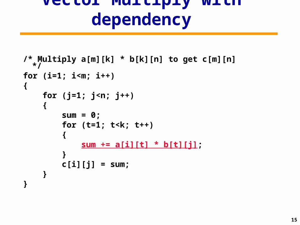
Vector Multiply with dependency
/* Multiply a[m][k] * b[k][n] to get c[m][n] */
for (i=1; i<m; i++){ for (j=1; j<n; j++) { sum = 0; for (t=1; t<k; t++) { sum += a[i][t] * b[t][j]; } c[i][j] = sum; }}
16
Novel Matrix Multiply Solution
• You don't need to do reductions for matrix multiply• You can calculate multiple independent sums within one
vector register• You can vectorize the outer (j) loop to perform
32 dot-products at the same time• Or you can think of each 32 Virtual Processors doing one of
the dot products– (Assume Maximum Vector Length is 32)
• Show it in C source code, but can imagine the assembly vector instructions from it
17
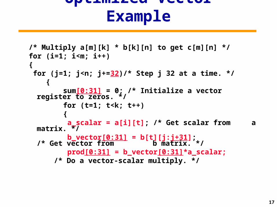
Optimized Vector Example
/* Multiply a[m][k] * b[k][n] to get c[m][n] */for (i=1; i<m; i++){ for (j=1; j<n; j+=32)/* Step j 32 at a time. */ { sum[0:31] = 0; /* Initialize a vector
register to zeros. */ for (t=1; t<k; t++) { a_scalar = a[i][t]; /* Get scalar from
a matrix. */ b_vector[0:31] = b[t][j:j+31];
/* Get vector from b matrix. */
prod[0:31] = b_vector[0:31]*a_scalar; /* Do a vector-scalar multiply. */
18
Optimized Vector Example cont’d
/* Vector-vector add into results. */ sum[0:31] += prod[0:31]; }
/* Unit-stride store of vector of results. */
c[i][j:j+31] = sum[0:31]; }}
19
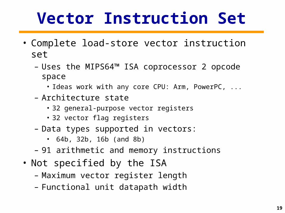
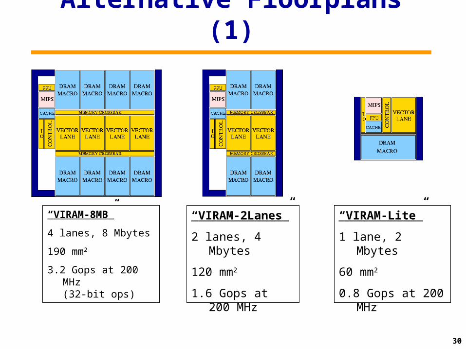
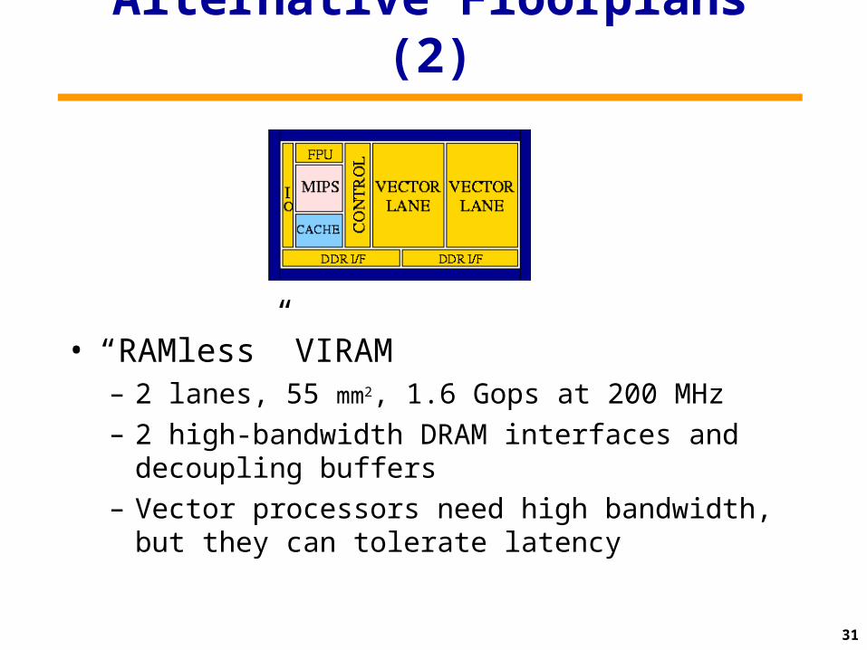
Vector Instruction Set
• Complete load-store vector instruction set– Uses the MIPS64™ ISA coprocessor 2 opcode space
– 2 high-bandwidth DRAM interfaces and decoupling buffers
– Vector processors need high bandwidth, but they can tolerate latency
32
Power Consumption
• Power saving techniques– Low power supply for logic (1.2 V)
• Possible because of the low clock rate (200 MHz)• Wide vector datapaths provide high performance
– Extensive clock gating and datapath disabling• Utilizing the explicit parallelism information of vector
instructions and conditional execution
– Simple, single-issue, in-order pipeline
• Typical power consumption: 2.0 W– MIPS core: 0.5 W – Vector unit: 1.0 W (min ~0 W)– DRAM: 0.2 W (min ~0 W)– Misc.: 0.3 W (min ~0 W)
33
Outline
• Motivation and goals• Vector instruction set• Vector IRAM prototype
– Microarchitecture and design
• Vectorizing compiler• Performance
– Comparison with SIMD
34
VIRAM Compiler
• Based on the Cray’s PDGCS production environment for vector supercomputers
• Extensive vectorization and optimization capabilities including outer loop vectorization
• No need to use special libraries or variable types for vectorization
Optimizer
C
Fortran95
C++
Frontends Code Generators
Cray’s
PDGCS
T3D/T3E
SV2/VIRAM
C90/T90/SV1
35
Exploiting 0n-Chip Bandwidth• The vector ISA + compiler technology uses high bandwidth to mask latency• Compiled matrix-vector multiplication: 2 Flops/element
– Easy compilation problem; stresses memory bandwidth– Compare to 304 Mflops (64-bit) for Power3 (hand-coded)
0
100
200
300
400
500
600
700
800
900
MFLO
PS
mvm
32-bit,
8 b
anks
mvm
32-bit,
16 b
anks
mvm
64-bit,
8 b
anks
mvm
64-bit,
16 b
anks
1 lane
2 lane
4 lane
8 lane
–Performance normally scales with number of lanes–Need more memory banks than default DRAM macro
36
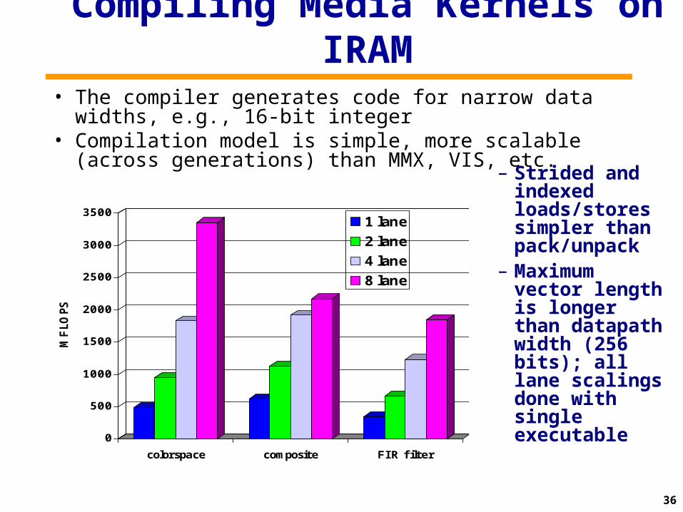
Compiling Media Kernels on IRAM• The compiler generates code for narrow data widths, e.g., 16-bit
integer• Compilation model is simple, more scalable (across generations)
than MMX, VIS, etc.
0
500
1000
1500
2000
2500
3000
3500
MFLO
PS
colorspace composite FIR filter
1 lane
2 lane
4 lane
8 lane
– Strided and indexed loads/stores simpler than pack/unpack
– Maximum vector length is longer than datapath width (256 bits); all lane scalings done with single executable
37
Compiler Challenges
• Generate code for variable data type width– Vectorizer starts with largest width (64b)– At the end, vectorization discarded if greatest width met
is smaller; vectorization restarted– For simplicity, a single loop will use the largest width
present in it
• Consistency between scalar cache and DRAM– Problem when vector unit writes cached data– Vector unit invalidates cache entries on writes– Compiler generates synchronization instructions
• Vector after scalar, scalar after vector • Read after write, write after read, write after write
38
Outline
• Motivation and goals• Vector instruction set• Vector IRAM prototype
– Microarchitecture and design
• Vectorizing compiler• Performance
– Comparison with SIMD
39
Performance: Efficiency
Peak Sustained % of Peak
Image Composition 6.4 GOPS 6.40 GOPS 100%
iDCT 6.4 GOPS 3.10 GOPS 48.4%
Color Conversion 3.2 GOPS 3.07 GOPS 96.0%
Image Convolution 3.2 GOPS 3.16 GOPS 98.7%
Integer VM Multiply 3.2 GOPS 3.00 GOPS 93.7%
FP VM Multiply 1.6 GFLOPS 1.59 GFLOPS 99.6%
Average 89.4%
40
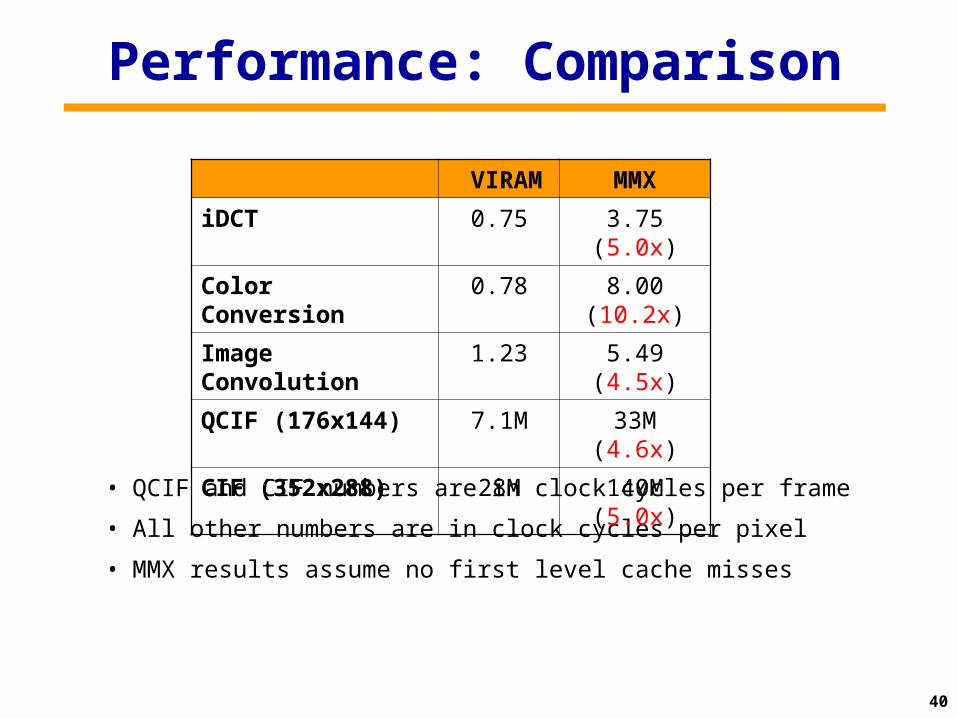
Performance: Comparison
• QCIF and CIF numbers are in clock cycles per frame
• All other numbers are in clock cycles per pixel
• MMX results assume no first level cache misses
VIRAM MMX
iDCT 0.75 3.75 (5.0x)
Color Conversion 0.78 8.00 (10.2x)
Image Convolution 1.23 5.49 (4.5x)
QCIF (176x144) 7.1M 33M (4.6x)
CIF (352x288) 28M 140M (5.0x)
41
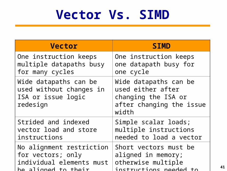
Vector Vs. SIMD
Vector SIMDOne instruction keeps multiple datapaths busy for many cycles
One instruction keeps one datapath busy for one cycle
Wide datapaths can be used without changes in ISA or issue logic redesign
Wide datapaths can be used either after changing the ISA or after changing the issue width
Strided and indexed vector load and store instructions
Simple scalar loads; multiple instructions needed to load a vector
No alignment restriction for vectors; only individual elements must be aligned to their width
Short vectors must be aligned in memory; otherwise multiple instructions needed to load them