IRD-fli73 034 ENVIRONMENTAL IMPACT RESEARCH PROGRAM PRESS SEEDER AMD Ill I PUNCH. SEEDER SECTI.. (U) RMY ENGINEER NATERNAYS I EXPERIMENT STATION VICKSBURG MS ENYIR.. T 3 DOERR 7 7 JUL 86 NEUS/TR/EL-89 F/6 03/2 NM.
Transcript
IRD-fli73 034 ENVIRONMENTAL IMPACT RESEARCH PROGRAM PRESS SEEDER AMD IllI PUNCH. SEEDER SECTI.. (U) RMY ENGINEER NATERNAYSI EXPERIMENT STATION VICKSBURG MS ENYIR.. T 3 DOERR7 7 JUL 86 NEUS/TR/EL-89 F/6 03/2 NM.
I'I.
1111 t. LA IM,
11111 .25 1M1 1 .2
MICROCOPY RESOLUTION TEST CHARTNATIONAL BURAEAU OF STANOARDS-1963-A
ENVIRONMENTAL IMPACTRESEARCH PROGRAM
TECHNICAL REPORT EL-86-49
4PRESS SEEDER AND PUNCH SEEDER
Section 8.4.4, US ARMY CORPS OF ENGINEERSWILDLIFE RESOURCES MANAGEMENT MANUAL
y byUTed B. Doerr
Environmental Laboratory -
DEPARTMENT OF THE ARMY
Waterways Experiment Station, Corps of Engineers b'2I%:.
PO Box 631, Vicksburg, Mississippi 39180-0631
' '=DTICEIFLECT E
OCT1 I I
• July 1986
lit- ..... Final Report -- %
Approved For Public Release; Distribution Unlimited . --
,.
Prepared for DEPARTMENT OF THE ARMYUS Army Corps of EngineersWashington, DC 20314-1000
This work was sponsored by the Office, Chief of Engineers (OCE), US Army,
as part of the Environmental Impact Research Program (EIRP), Work Unit 31631,
entitled Management of Corps Lands for Wildlife Resource Improvement. The
Technical Monitors for the study were Dr. John Bushman and Mr. Earl Eiker,
OCE, and Mr. Dave Mathis, Water Resources Support Center.
This report was prepared by Mr. Ted B. Doerr, Range Science Department,
Colorado State University, Fort Collins, Colo. Mr. Doerr was employed by the
Environmental Laboratory (EL), US Army Engineer Waterways Experiment Sta-
tion (WES), under an Intergovernmental Personnel Act contract with Colorado
State University during the period this report was prepared. Mr. Chester 0.
Martin, Team Leader, Wildlife Resources Team, Wetlands and Terrestrial Habitat
Group (WTHG), EL, was principal investigator for the work unit. Mr. Dan W.
McKenzie, USDA Forest Service, Equipment Development Center, San Dimas,
Calif., provided equipment specifications and photographs used to prepare line
drawings. Review and comments were provided by Mr. Martin, WES, and
Mr. Larry E. Marcy, Texas A&M University.
The report was prepared under the general supervision of Dr. Hanley K. "
Smith, Chief, WTHG, EL; Dr. Conrad J. Kirby, Chief, Environmental Resources
Division, EL; and Dr. John Harrison, Chief, EL. Dr. Roger T. Saucier, WES,
the WES Information Products Division (IPD). Drawings were prepared by
Mr. John R. Harris, Scientific Illustrations Section, IPD, under the super-
vision of Mr. Aubrey W. Stephens, Jr.
COL Allen F. Grum, USA, was the previous Director of WES. COL Dwayne G.
Lee, CE, is the present Commander and Director. Dr. Robert W. Whalin is
Technical Director.
This report should be cited as follows: .,
Doerr, Ted B. 1986. "Press Seeder and Punch Seeder: Sec- 0oltion 8.4.4, US Army Corps of Engineers Wildlife Resources ManagementManual," Technical Report EL-86-49, US Army Engineer WaterwaysExperiment Station, Vicksburg, Miss. '....l. , , tio .! . ...... . . .1
Limitations . . o . . . . . . . 5 LITERATURE CITED ......... 8
PUNCH SEEDER. . . . . . . . . . . 5
The Oregon press seeder and the punch seeder are specialized seeders that
currently have limited application. Although not considered similar in
design, both types of seeders are described in this report for convenience of
presentation.
PRESS SEEDER
The Oregon press seeder is a specialized drill seeder developed by the
USDA Forest Service and Oregon State University for use on light, loose soils
in sagebrush areas. The seeder firms the seedbed, creates planting furrows,
plants the seeds, and covers the seeds in the furrows. Press seeders are not
widely used because of the flexibility of the rangeland drill to a large
variety of sites; however, they have utility on construction sites and wild-life habitat restoration projects where the soil is loose and dry (silty and
sandy soils with little structure).
Description
The Oregon press seeder has 12 frame-mounted, independently suspended
steel press wheels, each with a V-shaped ridge (Larson 1980). A seedbox is
mounted ismediately behind the press wheels with 12 long seed tubes to direct MrM
seed into the furrows created by the press wheels (Fig. 1). The furrows are
covered by drag chains attached to the bottom of each seed tube. Further
The press seeder is pulled behind a tractor during the seeding operation.
The press wheels support the weight of the seeder, firm the seedbed, and cre-
ate the seed furrows (Booster 1961, Vallentine 1971). Each press wheel can
individually follow the land contour and pass over minor obstructions. The
seedbox agitator and metering system are synchronized with the press wheel
rotation by a gear-chain system similar to those found on other drill seeders. .
Seed are dropped into the furrow created by the press wheel and covered with
loose soil (Larson 1980). Packed soil under the seed forms a firm seedbed,
while leaf growth is unobstructed by the cover of loose soil.
Limitations
Oregon press seeders must be custom built and are not adapted to highly
rocky soils or areas with dense litter and brush. The press seeder is most
effective on loose dry soils (Booster 1961), but is not as effective on wet,
firm soils as are other types of drill seeders (Vallentine 1971). Frequent
breakdowns may also be a problem. The press seeder is difficult to transport
without special equipment and techniques. Further information on press
seeders may be obtained from the USDA Forest Service, Equipment Development -4 Center, 444 E. Bonita Ave., San Dimas, California 91773.
PUNCH SEEDER
The punch seeder is a specialized piece of equipment designed to seed
fragile, arid soils and other areas where surface disturbance needs to be kept
to a minimum (USDA Forest Service 1982). The punch seeder creates a hole in
the soil and places seed at a greater depth than can be accomplished by drill -%
seeding; this establishes a more favorable temperature and moisture regime for
seed germination and seedling survival (Moden and McKenzie 1982). Punch seed-
ing was first developed for vegetable crops (Cary 1967, Heineman et al. 1973,
Wilkins et al. 1979) but has since been tested on range sites in Texas (Hauser1981) and Idaho (Moden 1983) with positive results. A punch seeder design is
currently being tested by the USDA Forest Service Equipment Development Center
and the University of Idaho.
Description
The prototype punch seeder being field tested by the Forest Service is a
self-propelled, low-slung, modified tractor with the punch seeder mounted
6P. =
IVI° %IN
between the back tires. Commercial punch seeders will have several seeding
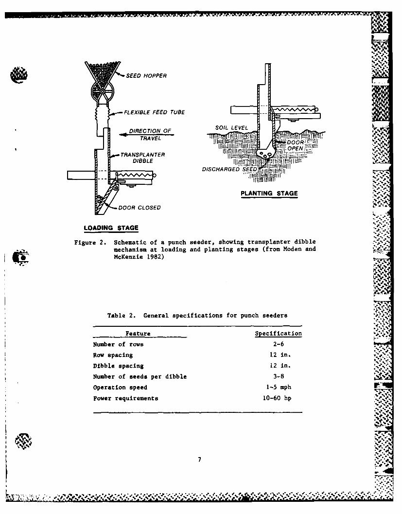
mechanisms mounted 12 in. apart on a tool bin frame. The punch seeder mecha- '.•', _oV
nism currently being used consists of a seedbox, metering system, flexible V
seed tube, and rigid tube (dibbler) with a protective gate (Fig. 2). The sys-
tem currently is driven by electricity but ultimately will be powered by the
motion of the support frame wheels. The circular motion of the wheel and axle
that will be used to meter and agitate the seeds will be converted by a crank k •
into a piston action to push the dibbler into the ground. Other specifica-
tions are listed in Table 2.
Operation
Commercial-type punch seeders will be towed 1 to 5 mph behind a tractor
and will be able to seed 8 to 32 acres a day (Moden and McKenzie 1982). Seed
will be pulled from the seedbox by agitators and gravity-fed into a metering
device that dumps the correct number of seeds into the seed tube. The seeds
will pass into the rigid tube and rest at the bottom. As the electric drive -1mechanism inserts the rigid tube 1 to 3 in. into the ground, the gate opens . '
and allows the seeds to fall to the bottom of the hole (Fig. 2) (Hauser 1981,
Moden and McKenzie 1982, Moden 1983). The dibbler is then retracted as the -6. .. V'
machine moves forward. The holes will not be filled with soil, but natural - .
soil sloughing will occur to cover seed sufficiently without burying them too
deeply (Moden 1983). %-1
Limitations "
Punch seeding equipment is still in the developmental stage and therefore,.- "
is not available unless custom manufactured. Because it is experimental, the
durability of equipment is not known and costs are only estimates. Punch
seeding will be more expensive than broadcast or drill seeding and should be
considered only for critical areas where vegetation establishment is difficult
and soil disturbance must be kept to a minimum. The punch seeder is not
commercially available at this time. Additional information may be obtained
from the USDA Forest Service, Equipment Development Center, San Dimas,
California.
I6,- ....
' ..7
SEED HOPPER
FLEXIBLE FEED TUBE
DIRECTION OF XL
DDOOR CLOSED
LOADING STAGES
Figure 2. Schematic of a punch seeder, showing transplanter dibblemechanism at loading and planting stages (from Moden andMcKenzie 1982)