MikroElektronika IrDA to PC ™ Manual All Mikroelektronika’s development systems feature a large number of peripheral modules expanding microcontroller’s range of application and making the process of program testing easier. In addition to these modules, it is also possible to use numerous additional modules linked to the development system through the I/O port connectors. Some of these additional modules can operate as stand-alone devices without being connected to the microcontroller. Additional Board Downloaded from Elcodis.com electronic components distributor
Transcript
MikroElektronika
IrDA to PC™
Manual
All Mikroelektronika’s development systems feature a large number of peripheral modules expanding microcontroller’s range of application and making the process of program testing easier. In addition to these modules, it is also possible to use numerous additional modules linked to the development system through the I/O port connectors. Some of these additional modules can operate as stand-alone devices without being connected to the microcontroller.
Addi
tiona
l Boa
rd
Downloaded from Elcodis.com electronic components distributor
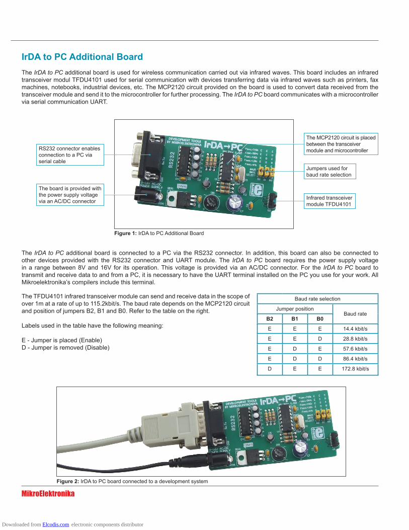
IrDA to PC Additional BoardThe IrDA to PC additional board is used for wireless communication carried out via infrared waves. This board includes an infrared transceiver modul TFDU4101 used for serial communication with devices transferring data via infrared waves such as printers, fax machines, notebooks, industrial devices, etc. The MCP2120 circuit provided on the board is used to convert data received from the transceiver module and send it to the microcontroller for further processing. The IrDA to PC board communicates with a microcontroller via serial communication UART.
Figure 1: IrDA to PC Additional Board
Figure 2: IrDA to PC board connected to a development system
Infrared transceiver module TFDU4101
RS232 connector enables connection to a PC via serial cable
The board is provided with the power supply voltage via an AC/DC connector
The TFDU4101 infrared transceiver module can send and receive data in the scope of over 1m at a rate of up to 115.2kbit/s. The baud rate depends on the MCP2120 circuit and position of jumpers B2, B1 and B0. Refer to the table on the right.
Labels used in the table have the following meaning:
E - Jumper is placed (Enable)D - Jumper is removed (Disable)
Jumpers used for baud rate selection
Baud rate selection
Jumper positionBaud rate
B2 B1 B0
E E E 14.4 kbit/s
E E D 28.8 kbit/s
E D E 57.6 kbit/s
E D D 86.4 kbit/s
D E E 172.8 kbit/s
The MCP2120 circuit is placed between the transceiver module and microcontroller
The IrDA to PC additional board is connected to a PC via the RS232 connector. In addition, this board can also be connected to other devices provided with the RS232 connector and UART module. The IrDA to PC board requires the power supply voltage in a range between 8V and 16V for its operation. This voltage is provided via an AC/DC connector. For the IrDA to PC board to transmit and receive data to and from a PC, it is necessary to have the UART terminal installed on the PC you use for your work. All Mikroelektronika’s compilers include this terminal.
Downloaded from Elcodis.com electronic components distributor