111
iRIS Datalogger User Guide Applies to: iRIS 220, iRIS 320, iRIS 350 Excludes: iRIS 150, iRIS 300 For Software Version: V1.50+ (Requires Firmware Version: V2.50+)

iRIS Datalogger User Guide
Applies to: iRIS 220, iRIS 320, iRIS 350
Excludes: iRIS 150, iRIS 300
For Software Version: V1.50+ (Requires Firmware Version: V2.50+)

iQuest (NZ) Ltd - PO Box 15169, Hamilton, New Zealand Tel: +64 7 857-0810 Fax: +64 7 857-0811 Email: [email protected]
Revision History
Issue 1 Version 1.45RC 16th June 2009 Interim release of the merged product version of this guide for software release candidate V1.45. This is the precursor to official software release 1.50. Note: All version labels in this manual are 1.50 in anticipation.
Disclaimer Under no circumstances will iQuest (NZ) Ltd be liable or responsible for any consequential damage or loss that may arise from the use of this product. All examples and diagrams shown in this manual and any supplied software examples are intended as a guide to understanding this product, not to guarantee operation. iQuest (NZ) Ltd accepts no responsibility for use of this product based on this information or these examples. Owing to the wide variety of possible applications of this product, you must satisfy yourself as to its suitability to your specific application. © 2003-2009, iQuest (NZ) Ltd All rights reserved. This publication, or any part of it, and any software accompanying it may not be copied, photocopied, reproduced, translated or communicated to any third party, or reduced to electronic medium without prior written permission from iQuest (NZ) Ltd.
iRIS Datalogger User Guide V1.50
i iQuest (NZ) Ltd - PO Box 15169, Hamilton, New Zealand Tel: +64 7 857-0810 Fax: +64 7 857-0811 Email: [email protected]
Contents 1 Introduction....................................................................................................................................1
1.1 About this Manual......................................................................................................................1 1.2 Support......................................................................................................................................1
2 Overview.........................................................................................................................................2 2.1 Introduction................................................................................................................................2 2.2 Features....................................................................................................................................2 2.3 Typical Applications ...................................................................................................................2 Key Common Features....................................................................................................................3
2.3.1 Terminal Configuration ........................................................................................................3 2.3.2 Wireless IP Connectivity......................................................................................................3 2.3.3 Alternative Wireless Connectivity (CSD/SMS)......................................................................3 2.3.4 Power Management ............................................................................................................4 2.3.5 Data Logging.......................................................................................................................4 2.3.6 Logged Data Array Identification..........................................................................................5 2.3.7 Alarm Processing ................................................................................................................5 2.3.8 Real Time Clock & Calendar ...............................................................................................5 2.3.9 Security...............................................................................................................................5 2.3.10 Gateway Communication ..................................................................................................6
2.4 iRIS 220/320 and iRIS 350 Comparison.....................................................................................6 3 Installation – All Models ................................................................................................................7
3.1 Removing/Replacing the Electronic Assembly - iRIS 220 ...........................................................7 3.2 Opening / Closing the Housing - iRIS 320 / iRIS 320V................................................................7 3.3 Opening / Closing the Housing - iRIS 350 / iRIS 350V................................................................7 3.4 Removing / fitting the SIM card (GSM and HSDPA (3G) models) ...............................................8 3.5 I/O Connector ............................................................................................................................8
3.5.1 Internal Battery....................................................................................................................9 3.5.2 Internal / External 12V Battery Supply .................................................................................9 3.5.3 External (Charger) Power Supply ........................................................................................9 3.5.4 Analog I/O.........................................................................................................................10 3.5.5 Digital I/O..........................................................................................................................11
4 Configuration ............................................................................................................................... 14 4.1 Terminal Connection................................................................................................................14 4.2 Terminal Security Code ...........................................................................................................14 4.3 Terminal Cfg............................................................................................................................15 4.4 Terminal Menus.......................................................................................................................17
4.4.1 Main Menu (Level 1)..........................................................................................................17 4.4.2 Main Menu (Level 1)..........................................................................................................18 4.4.3 Comms Cfg (Level 2) ........................................................................................................19 4.4.4 GPRS / 3G / CDMA-1X Cfg (Level 3) ................................................................................22 4.4.5 Phone List (Level 3) ..........................................................................................................24 4.4.6 IP Acceptance Cfg (Level 4) .............................................................................................. 25 4.4.7 IP Connection Schedule Cfg (Level 4) ...............................................................................25 4.4.8 Sensor Selection (Level 2) ................................................................................................ 27 Sensor Cfg (Level 3) ..................................................................................................................28 4.4.9 Alarm Selection (Level 4) ..................................................................................................31 4.4.10 Alarm Cfg (Level 5) .........................................................................................................31 4.4.11 Output Selection (Level 2) ............................................................................................... 32 4.4.12 Output Cfg (Level 3) ........................................................................................................32 4.4.13 Date/Time Cfg (Level 2) ..................................................................................................35 4.4.14 Miscellaneous Menu (Level 2) .........................................................................................36 4.4.15 Voice Menu (Level 2) ......................................................................................................36

iRIS Datalogger User Guide V1.50
ii iQuest (NZ) Ltd - PO Box 15169, Hamilton, New Zealand Tel: +64 7 857-0810 Fax: +64 7 857-0811 Email: [email protected]
5 Operation......................................................................................................................................37 5.1 LED Indicators.........................................................................................................................37
5.1.1 Status LED........................................................................................................................37 5.1.2 Diagnostic LEDs................................................................................................................37
5.2 LCD & Keypad.........................................................................................................................38 5.2.1 LCD Operation..................................................................................................................38 5.2.2 Status Icons ......................................................................................................................38 5.2.3 Keypad Buttons.................................................................................................................38 5.2.4 Display Menu Structure .....................................................................................................39 5.2.5 Primary LCD Display Screens ...........................................................................................40 5.2.6 Sensor Related Screens....................................................................................................41 5.2.7 Totaliser Related Screens .................................................................................................44 5.2.8 Comms Related Screens...................................................................................................44
5.3 SMS Communication ...............................................................................................................48 5.3.1 SMS Text Commands .......................................................................................................48
5.4 General Hints ..........................................................................................................................48 6 Sensor Connection Examples.....................................................................................................49
6.1 Introduction to Connection Examples .......................................................................................49 6.2 Connecting a Flow Meter or Rain Gauge..................................................................................50 6.3 Connecting a 0-5V Pressure Transducer..................................................................................51 6.4 Connecting a 2-Wire Loop-Powered 4-20mA Sensor ............................................................... 52 6.5 Connecting an Up/Down Water Level Instrument .....................................................................53 6.6 Connecting a Unidata High-Speed Serial Instrument................................................................ 54 6.7 Connecting Analog Wind Instruments ......................................................................................55 6.8 Connecting SDI-12 Instruments ............................................................................................... 56 6.9 Connecting Quadrature Encoders ............................................................................................57
6.9.1 iRIS 350 Installation ..........................................................................................................57 6.9.2 iRIS 220 / iRIS 320 Installation ..........................................................................................58
6.10 Connecting a Vaisala WXT5x0 Weather Transmitter .............................................................. 59 6.10.1 Configuration...................................................................................................................59 6.10.2 Vaisala Configuration Software Settings ..........................................................................60 6.10.3 iRIS Sensor Configuration ............................................................................................... 61
7 Using iLink’s Sensor Configuration Tool....................................................................................62 7.1 iRIS Sensor Configuration Example .........................................................................................62
8 Analog Input Scaling ...................................................................................................................65 8.1 Example: A 4-20mA Water Level Sensor .................................................................................65
9 RS232 Interface Telemetry / Gateway Comms............................................................................66 9.1 Overview .................................................................................................................................66 9.2 RS232 Port Telemetry .............................................................................................................66
9.2.1 RS232 Only Telemetry Mode ............................................................................................66 9.2.2 Non-Dedicated RS232 Telemetry Mode ............................................................................66
9.3 Gateway Communication.........................................................................................................67 9.3.1 Aliased Gateway explained ............................................................................................... 68 9.3.2 Gateway Example.............................................................................................................68
iRIS Datalogger User Guide V1.50
iii iQuest (NZ) Ltd - PO Box 15169, Hamilton, New Zealand Tel: +64 7 857-0810 Fax: +64 7 857-0811 Email: [email protected]
10 Troubleshooting.........................................................................................................................69 10.1 Can’t connect to the iRIS via the RS232 port..........................................................................69 10.2 iRIS will not start when the battery is first connected .............................................................. 69 10.3 Pulse lost when iRIS connected to other equipment ............................................................... 69 10.4 Unable to connect to a GPRS or 3G network .........................................................................69 10.5 Unable to connect to a CDMA network...................................................................................69 10.6 iRIS will not respond to SMS requests ...................................................................................69 10.7 iRIS will not answer CSD data calls........................................................................................70 10.8 iRIS 3x0V answers a voice call, but no sound is heard ...........................................................70 10.9 CDMA iRIS 3x0V answers a voice call, but a modem sound is heard .....................................70 10.10 Logged data limits at a value like 32767 ...............................................................................70 10.11 Unable to access terminal menu ..........................................................................................70 10.12 Digital output activates when user is logged on ....................................................................70
11 Appendix A – iRIS 350 Specific Information .............................................................................71 11.1 General Characteristics – iRIS 350 ........................................................................................71 11.2 Technical Specifications – iRIS 350 / iRIS 350V.....................................................................72 11.3 Mounting – iRIS 350 / iRIS 350V............................................................................................73 11.4 Antenna Connection ..............................................................................................................73
12 Appendix B – iRIS 220 Specific Information .............................................................................74 12.1 General Characteristics – iRIS 220 ........................................................................................74 12.2 Technical Specifications – iRIS 220 .......................................................................................75 12.3 Mounting – iRIS 220 ..............................................................................................................76 12.4 Antenna Connection ..............................................................................................................76
13 Appendix C – iRIS 320 Specific Information .............................................................................77 13.1 General Characteristics – iRIS 320 ........................................................................................77 13.2 Technical Specifications – iRIS 320 / iRIS 320V.....................................................................78 13.3 Mounting – iRIS 320 / iRIS 320V............................................................................................79 13.4 Antenna Connection ..............................................................................................................79
14 Appendix D – Voice Annunciation (iRIS 3x0V) .........................................................................80 14.1 Recording Wave Files Using Sound Recorder........................................................................81 14.2 Loading Wave Files into the iRIS ...........................................................................................83
14.2.1 Audio File Settings ..........................................................................................................84 14.2.2 Audio Script Settings .......................................................................................................85 14.2.3 Uploading Audio Files over a Remote Connection ...........................................................86
15 Appendix E - Using an iRIS-CAM Camera.................................................................................87 15.1 Overview ............................................................................................................................... 87 15.2 Specifications ........................................................................................................................87 15.3 Mounting ............................................................................................................................... 88 15.4 Connecting the iRIS-CAM......................................................................................................89 15.5 Installing PC Based Software & USB Drivers .........................................................................89 15.6 Connecting to the PC.............................................................................................................90 15.7 Focusing................................................................................................................................ 91 15.8 iRIS Configuration..................................................................................................................91
15.8.1 Installing iRIS Software for Camera Support ....................................................................91 15.8.2 Configure the Camera on the iRIS...................................................................................91

iRIS Datalogger User Guide V1.50
iv iQuest (NZ) Ltd - PO Box 15169, Hamilton, New Zealand Tel: +64 7 857-0810 Fax: +64 7 857-0811 Email: [email protected]
16 Appendix F – Upgrading Firmware/Software............................................................................93 16.1 Overview ............................................................................................................................... 93 16.2 File Naming Conventions.......................................................................................................93
16.2.1 iRIS Executive Firmware. ................................................................................................ 93 16.2.2 iRIS Application Software. ............................................................................................... 93
16.3 iRIS Automated Upgrade Procedure ......................................................................................94 16.4 GSM/GPRS Modem Core Firmware Upgrade Procedure .......................................................98
17 Appendix G – SDI-12................................................................................................................ 101 17.1 What is SDI-12? .................................................................................................................. 101 17.2 Advantages of SDI-12.......................................................................................................... 101 17.3 SDI-12 Electrical Interface ................................................................................................... 102
18 Appendix H – Internal Database Locations............................................................................. 103 19 Appendix I - Network Settings for iQuest APN or iQuest Global Data Network .................... 104 20 User Notes................................................................................................................................ 105
Tables / Figures Table 1 - Feature Summary ......................................................................................................................... 2 Table 2 - Hardware Differences.................................................................................................................... 6 Table 3 - Standard Sensor Sources ............................................................................................................28 Table 4 - Internal Sensor Sources ...............................................................................................................29 Table 5 - Supplementary Logging Flag Definitions.......................................................................................30 Table 6 - Status LED Indication Modes .......................................................................................................37 Table 7 - I/O Terminal Differences...............................................................................................................49 Table 8 – RS232 Port Telemetry Control .....................................................................................................66 Table 9 – RS232 Telemetry Mode Indications .............................................................................................66 Figure 1 - SIM Carrier .................................................................................................................................. 8 Figure 2 - I/O Connector .............................................................................................................................. 8 Figure 3 - Simplified iRIS 350 Analog Input Circuit ......................................................................................10 Figure 4 - iRIS 350 Analog Input / Output Links...........................................................................................10 Figure 5 - Digital Input Circuit ......................................................................................................................11 Figure 6 - iRIS 220 / iRIS320 Digital Input Debounce Links .........................................................................12 Figure 7 - iRIS 350 Digital I/O Debounce Links............................................................................................12 Figure 8 - Digital Output Pull-Down Mode Circuit.........................................................................................13 Figure 9 - Digital Output Switched 12V Mode Circuit ...................................................................................13 Figure 10 - RS232 Cable Pin Designations .................................................................................................14 Figure 11 - Terminal Menu Structure...........................................................................................................17 Figure 12 - Typical RS232 / Data Radio Cable ............................................................................................67 Figure 13 - iRIS 350 / iRIS 350V .................................................................................................................71 Figure 14 - iRIS 350 / iRIS 350V Mounting Diagram....................................................................................73 Figure 15 - iRIS 220....................................................................................................................................74 Figure 16 - iRIS 220 Mounting Diagram ......................................................................................................76 Figure 17 - iRIS 320 / iRIS 320V .................................................................................................................77 Figure 18 - iRIS 320 / iRIS 320V Mounting Diagram....................................................................................79

1 iQuest (NZ) Ltd - PO Box 15169, Hamilton, New Zealand Tel: +64 7 857-0810 Fax: +64 7 857-0811 Email: [email protected]
1 Introduction
1.1 About this Manual This manual is intended as a detailed guide for the installation, configuration and operation of three of the iRIS datalogger range. The models covered are the current iRIS 350 and its predecessors the iRIS 220 and iRIS 320. This manual is also available on-line in Adobe Acrobat® pdf format for registered users at www.iquest.co.nz Throughout this document, small icons are used to identify additional information. These are as follows:
NOTE Indicates extra detail to expand the current discussion. WARNING Describes something that may cause problems if not heeded.
The term “iRIS” is used throughout this manual in reference to the iRIS datalogger where the description is common to all models. For model specific information, please refer to the appendices at the end of this document. The term “IP” is used throughout this manual to refer to the wireless modem IP connectivity, irrespective of whether the actual wireless modem is GPRS, HSDPA or CDMA. LCD Screen Examples All examples showing LCD screens are taken from an iRIS 350. This model has 19 characters of text per line compared to the iRIS 320 which has 12 characters. Therefore the text used on some screens may be slightly different between models. 1.2 Support Technical support for the iRIS datalogger family is available by contacting: iQuest (NZ) Ltd PO Box 15169 Dinsdale Hamilton 3243 NEW ZEALAND Tel: +64 7 857-0810 Fax: +64 7 857-0811 Email: [email protected] For latest information and software updates, visit the iQuest (NZ) Ltd web site at www.iquest.co.nz.
Access to the client area on the website requires a log-in which is can also be used to access the iQuest forum. Self-registration is available by visiting the forum home page.

iRIS Datalogger User Guide V1.50
2 iQuest (NZ) Ltd - PO Box 15169, Hamilton, New Zealand Tel: +64 7 857-0810 Fax: +64 7 857-0811 Email: [email protected]
2 Overview
2.1 Introduction The iRIS (iQuest Remote Information Source) datalogger range has been designed as cost effective, low power, self-contained information sources for use in a wide range of data gathering and logging applications. The iRIS achieves network connectivity through the use of an integral wireless modem. Depending on the application and target market, this modem will be one of the following:
Multi-band 900 / 1800 / 1900 MHz GSM/GPRS 3G HSDPA / WCDMA (for example Telecom XT® in New Zealand and Telstra NextG® in Australia) CDMA-1X (this is a legacy technology that is not available for the iRIS 350)
This modem also supports the alternative connection options of CSD (Circuit Switched Data) and SMS (Short Message Service). These options require the appropriate service to be enabled by the wireless service provider. 2.2 Features
Wire
less
IP M
ode
SMS
Mod
e
CSD
Mod
e
Voic
e A
nnun
ciat
ion
Supp
ort
IRIS
-CA
M C
amer
a S
uppo
rt
Dig
ital i
nput
s (p
ulse
, fre
quen
cy c
ount
er)
Ana
log
Inpu
ts (0
-5V
or 0
-20m
A)
Dig
ital C
ontr
ol O
utpu
ts
SDI-1
2 In
terf
ace
*
RS-
232
Inte
rfac
e
Num
ber
of S
imul
tane
ous
Logg
ing
Cha
nnel
s
Inte
rnal
Tem
pera
ture
Log
ging
Inte
rnal
Bat
tery
Log
ging
Supp
ly V
olta
ge L
oggi
ng
Ala
rms
per C
hann
el (s
enso
rs 1
-6)
Rat
ed a
t IP6
5 or
bet
ter
Hea
vy D
uty
Alu
min
ium
Cas
e
Inte
rnal
3.6
V Li
thiu
m B
acku
p B
atte
ry
Inte
rnal
12V
Rec
harg
eabl
e B
atte
ry
Inte
rnal
Bat
tery
Cha
rger
Dire
ct S
olar
Pan
el C
onne
ctio
n
Exte
rnal
RF
Ant
enna
Con
nect
or (S
MA
)
Key
pad
/ LC
D
iRIS 220 2 4 2 9 2
iRIS 320 2 4 2 9 2
iRIS 320V 2 4 2 9 2
iRIS 350 2 4 2 9 2
iRIS 350V 2 4 2 9 2
*SDI-12 Interface supports up to a maximum of 6 channels with the exception of the Vaisala WXT5x0 option that caters for the special case of seven parameters (see Section 6.10).
Table 1 - Feature Summary
2.3 Typical Applications The iRIS can be used for a wide range of diverse applications, including but not limited to:
Rainfall measurement River level monitoring Water / power / gas metering Remote control
Wind measurement Mobile temperature monitoring Irrigation monitoring / control IP RS232 communications gateway

3 iQuest (NZ) Ltd - PO Box 15169, Hamilton, New Zealand Tel: +64 7 857-0810 Fax: +64 7 857-0811 Email: [email protected]
Key Common Features 2.3.1 Terminal Configuration All configuration and set-up parameters are modified via a standard ASCII terminal connected to the RS232 serial interface. This means that the user can configure the device without needing specialised configuration software installed on their computer specifically for this purpose. The iQuest datalogger support program, iLink includes a simple IP terminal tool (UDP Terminal) that allows set-up to be performed across the wireless network via ASCII socket A for GPRS models. Refer to Section 4.3 for details on the terminal setup.
A facility for configuring sensor and alarm parameters is provided in iLink (from version 3.5.2.3 onwards). This uses a graphical point-and-click interface and the settings can be retrieved from or sent to the logger via any available communication channel. The configuration can also be saved to or loaded from disk. See Section Error! Reference source not found..
2.3.2 Wireless IP Connectivity Wireless Internet Protocol connectivity is provided via an on-board modem. Through this interface it is possible to perform configuration changes and retrieve logged data. To facilitate IP connectivity with the GSM and HSDPA (3G) models, a suitably activated SIM card must be inserted in the device. For all models, it is also necessary to program the unit with appropriate IP connection settings through a terminal connected to the RS232 serial interface. The iRIS communicates over a GPRS or CDMA-1X network using UDP protocol via two concurrent data ports. Port A is used for ASCII communication and provides similar terminal functionality to that available through the RS232 serial interface. Port B is used for proprietary iQuest protocol (binary) communication and supports time series data retrieval and unsolicited alarm call-in to a HydroTel base station. This port is also used for auto reporting of data to a suitable base station such as the iQuest Data Network (https://data.iquest.co.nz), when the iRIS has been configured to use this mode. The HSDPA (3G) variant uses a single TCP connection to achieve communication with the base station. 2.3.3 Alternative Wireless Connectivity (CSD/SMS) Two other wireless connection modes other than IP are also possible. These are CSD (Circuit Switched Data) or SMS (Short Message Service). As with the IP mode described above in Section 2.3.2, using either CSD and/or SMS requires either a SIM card with relevant services enabled by the GSM/3G service provider, or in the case of CDMA-1X, the appropriate services enabled by the CDMA provider. The CSD option is achieved by establishing a dial-up modem connection across the wireless network. Once this link is connected, data retrieval and configuration can be performed in a similar manner to the IP mode. The SMS option works by sending a preset text message to up to two destination cellphones or SMS receivers. This message contains the iRIS site identification and the current values of all enabled sensors. See Section 5.3 for more information on using the SMS feature.
Irrespective of the modem call-back mode setting (IP or CSD or SMS), the iRIS will answer any incoming CSD calls and also respond to incoming SMS requests only when it is not connected using the wireless IP link. The modem call-back mode setting only changes the service that is used to notify an alarm or generate a communication test. In this case, the selected service and destination phone numbers are used to call a base modem (CSD) or send a text message (SMS).

iRIS Datalogger User Guide V1.50
4 iQuest (NZ) Ltd - PO Box 15169, Hamilton, New Zealand Tel: +64 7 857-0810 Fax: +64 7 857-0811 Email: [email protected]
2.3.4 Power Management The iRIS supports four power management modes which are described below. Power management features that operate in all modes include:
Deactivation of RS232 driver i.c when the DSR signal is not present (unless the unit is active in RS232 telemetry mode).
Turning off the backlight after a period of inactivity when no user is logged-in. Ability to activate an IP session at scheduled times of day for pre-set period even if the modem is
otherwise disabled in full power save mode.
No Power Save With power management disabled, the internal wireless modem is maintained in a powered on state even if an IP or CSD session is not currently active. While in this state, periodic signal strength measurements are made and it is possible to interrogate the internal modem using the AT command set via a terminal connected to the serial interface. All on-board communication, I/O and all status LED’s are permanently enabled in this mode. Partial Power Save With the power management mode set to Partial Save, the on-board LEDs are disabled but the internal wireless modem remains in the same fully active state as in the No Power Save mode. Full Power Save When power management is set to full save mode, the internal LEDs are disabled and the internal wireless modem remains in a powered off state until a wireless session is activated.
While the modem is in this state, it is not possible to obtain signal strength measurements or interrogate the modem via the AT command set using the Modem Terminal mode.
RS232 Only This mode is provided for applications where the internal modem is not used and telemetry is achieved by a data radio or modem connected to the RS232 port. When in this mode the RS232 port is used for all call-back communication. The RS232 port behaviour also changes depending on whether the iRIS is in “Normal” or “Telemetry” mode. See RS232 Interface Telemetry for further details on RS232 telemetry communications.
2.3.5 Data Logging The iRIS supports the logging of data from six virtual sensors, plus a further three internal data sources (battery voltage, supply voltage and logger temperature). Each of the six main virtual sensors can obtain information from one of the following data sources:
Analog Input on AIN1 – AIN4 Pulse Counter attached to DI1 or DI2 Simulated Pulse Counter enabled by DI1 or DI2 Frequency Counter attached to DI1 or DI2 Up/down Counter attached to DI1 and DI2 simultaneously Received Signal Strength Indication (RSSI) Internal Database Location (for values obtained via user script or communications link) High-speed Serial Instrument (Unidata format – 2 byte only) SDI-12 serial channel Quadrature shaft encoder Change of status on charger input (dc supply)

5 iQuest (NZ) Ltd - PO Box 15169, Hamilton, New Zealand Tel: +64 7 857-0810 Fax: +64 7 857-0811 Email: [email protected]
Each sensor can be set up to scale the raw data source into engineering units through the application of a multiplier and offset (slope and constant). The scaled value can be logged to non-volatile memory at rates between once per minute to once per hour or immediately in true event mode for pulse inputs.
As all logged data is stored in integer format, a logging multiplier is applied to the scaled value to maintain resolution. See Section 4.4.8, Option 7 for details on configuring the logging multiplier on a sensor.
It is also possible to configure a sensor to also log derived values such as minimum, maximum, standard deviation (all source types) or a calculated flow rate or volume (pulse type sources only). See the next section and also Section 4.4.8 for further details on configuring these extended logging features as part of the Sensor Cfg menus. 2.3.6 Logged Data Array Identification Each sensor’s logged data is identified by an array ID number. For the primary logged data, the ID is the sensor number itself. For the optional supplementary data (min, max, deviation, flow/vol), the array ID has an offset added to the sensor number that it is derived from. These ID offsets are as follows:
Minimum: +10 Maximum: +20 Deviation: +30 Flow/Vol +40
For example, Sensor 4 has been configured to log the average value, plus the maximum and standard deviation. Three data arrays will be logged for this sensor at each logging interval with IDs of 4, 24 and 34 respectively. In HydroTel these require point identifiers of 4/0, 24/0 and 34/0 respectively.
Array 0 (zero) is a special array identifier and is used a system event log. Currently this is only used to log a restart (either at the initial connection of power, on a watchdog reset or a user program start after an upgrade). The logged value in this case is always zero. In HydroTel the identifier for this item is 0/0.
2.3.7 Alarm Processing Each virtual sensor can be checked for two separate alarm conditions. Each alarm has separate trigger and reset levels, as well as an activation delay or accumulation period depending upon the data type. The alarm on Sensor 1 can also be used to control the digital outputs. See Sections 3.5.5 and 4.4.11 for further details on digital outputs. 2.3.8 Real Time Clock & Calendar The iRIS has a non-volatile real time clock that can be set by the user either through a terminal (RS232 or UDP) or remotely via proprietary iQuest protocol commands from software such as HydroTel™ or iLink. To enable user adjustment to minimise clock drift a menu option is provided to set a compensation offset for fine control. See Section 4.4.13. 2.3.9 Security The iRIS 3x0 can be configured with a PIN code to prevent unauthorised access to restricted information through the LCD and keypad. This is especially useful when the iRIS is installed in a location where it is accessible to the general public. Because the software is common to the models, this feature is provided, but irrelevant for the iRIS 220 which has no LCD or keypad through which log-on can be achieved. A second level of security is also provided to prevent access to the terminal via a serial connection. This is achieved by a security string that if used requires correct entry before access to the terminal is granted. See Section 4.2 for more details on using the security string.

iRIS Datalogger User Guide V1.50
6 iQuest (NZ) Ltd - PO Box 15169, Hamilton, New Zealand Tel: +64 7 857-0810 Fax: +64 7 857-0811 Email: [email protected]
2.3.10 Gateway Communication The iRIS supports iQuest protocol gateway functionality between the wireless network and the RS232 serial interface. This enables the unit to be used as a bridge between the wide area wireless network and a localised radio or other network. It is possible to connect a datalogger that does not have wireless capability such as the iQuest DS-4483 to the serial port of the iRIS and communicate with it via the gateway. Also, by connecting a data radio to the unit’s serial port it is possible to communicate with several devices in a multi-drop radio network from the wireless network. When the gateway option is enabled, any data packets that are not addressed to the iRIS and match the gateway criteria are readdressed and redirected. The port that the redirected packet is sent from depends on the configuration of the iRIS.
Refer to Section 9 - RS232 Interface Telemetry for further information on using the gateway.
2.4 iRIS 220/320 and iRIS 350 Comparison The iRIS 350 is the successor to the iRIS 320 (and its sub-model, the iRIS 220). The iRIS 350 hardware design is largely based on the iRIS 320 but with several enhancements. The current releases of firmware/software are virtually identical to the iRIS 220/320. The additional on-board resources will be utilised in future software developments. The key hardware differences between the models are:
iRIS 220/320 iRIS 350 Analog Inputs - 12 bit resolution
- Raw reading 0 to 5000mV - External sink resistors are required for current inputs. These are normally 250 ohm giving 0 to 5000mV for 0 to 20mA input signal.
- 16 bit resolution - Raw reading 0 to 5.0000V - Built in 100 ohm link selectable sink resistors for current sources. This produces input range 0 to 2.0000V for 0 to 20mA signal.
Analog Output (Excitation)
Fixed 5V Reference Variable 0-5V or 0-20mA active output. (Fixed in software 5V for initial version)
Digital I/O 2 x Inputs 1 x Pull-down Output 1 x Switched 12V Output
4 x Digital I/O channels that can be either inputs, or outputs (Fixed in software to iRIS 320 configuration for initial version)
Real Time Clock backup
Miniature soldered-in lithium coin cell. ~15 months life of cumulative backup while iRIS not powered up.
User replaceable “Snap-Hat” battery module. ~7 years life of cumulative backup while iRIS not powered up.
Onboard RAM 8KB 32KB LCD 4 lines x 12 character test plus a set of
fixed icons. Full graphics LCD 64 x 128 pixels. (Initial software emulates the iRIS 320 LCD, but has 4 lines x 19 character text)
iRIS-CAM Interface
Plug-in option board. Built in.
Table 2 - Hardware Differences
Important! Analog Input Scaling. Any user familiar with the earlier iRIS 220/320 will be immediately at home with the iRIS 350. However, the analog inputs in the iRIS 350 deliver raw values as floating-point volts (0.0000 to 5.0000) rather than integer millivolts (0 to 5000). Therefore any scaling multiplier / offset values chosen must take this difference into account.

7 iQuest (NZ) Ltd - PO Box 15169, Hamilton, New Zealand Tel: +64 7 857-0810 Fax: +64 7 857-0811 Email: [email protected]
3 Installation – All Models
3.1 Removing/Replacing the Electronic Assembly - iRIS 220 The electronic assembly is retained in the case by two end plates and held in place by the two connectors (I/O and RS232). Follow this procedure to gain access to the printed circuit board (PCB) to change the SIM card on GSM models (see Section 3.4) or to change the digital input links (see Section 3.5.5). To Remove: Undo the two mounting screws at the antenna end of the case (if fitted). Unplug the I/O connector. Unscrew the two retaining screws on the RS232 connector and remove the connector extension. The PCB can then be carefully removed by sliding it out of the outer case.
Once the I/O connector and RS232 connector extension have been removed, the PCB is no longer retained. Take care to prevent the PCB falling out of the case.
To Replace: Reverse the removal procedure to reassemble the unit. 3.2 Opening / Closing the Housing - iRIS 320 / iRIS 320V The front of the iRIS 320 enclosure is secured by three M5 machine screws with Allen Key® heads.
The two left-hand screws act as links to the hinges and should not be fully unscrewed.
To Open: Undo the right-hand screw completely and put in a safe place. Undo the two left-hand screws until their heads are just fully clear of the front’s face. The front should then be able to be swung open to the left, to a maximum angle of 90. To Close: Check that the green gasket is fully installed in its retaining groove. Gently swing the front closed to the right, pulling it slightly forwards if it appears to catch, before finally pressing it fully home and then tightening the three M5 screws securely to maintain the IP65 rating of the enclosure. Fit a new tamper-proof wire seal to the right-hand screw if required for security purposes. Slight adjustment of the screw may be required to align the holes in the screw and enclosure to enable the seal’s wire to be passed through. 3.3 Opening / Closing the Housing - iRIS 350 / iRIS 350V The front of the iRIS 350 enclosure is secured by four M4 machine screws with Phillips® heads.
There are two small plastic hinges on the left side of the case. These are designed to hold the lid once it is released.
To Open: Lift off the two grey plastic side covers to expose the screws securing the cover. Put them in a safe place. Undo all four screws. There is no need to remove them completely as they are retained in the lid. The front cover should then be able to be swung open to the left, to a maximum angle of 90. To Close: Check that the black seal is fully installed in its retaining groove and there are no wires likely to be trapped under the cover. Gently swing the front cover closed to the right, holding it straight while refitting the screws. Tighten screws securely to maintain the IP66 rating of the enclosure. Replace the grey plastic side covers. Finally ensure the black rubber sealing cap is refitted to protect the RS232 connector.

iRIS Datalogger User Guide V1.50
8 iQuest (NZ) Ltd - PO Box 15169, Hamilton, New Zealand Tel: +64 7 857-0810 Fax: +64 7 857-0811 Email: [email protected]
3.4 Removing / fitting the SIM card (GSM and HSDPA (3G) models)
Important! Ensure the iRIS is depowered before attempting to remove or fit the SIM card. Exercise care when inserting or removing the SIM card, as the carrier is fragile.
Open the front cover as described above. Using a fingernail or small screwdriver inserted into one of the two oval holes on the sliding holder, gently lower the slide downwards to unlock it. The slide can now be swung forwards from its top end to enable the SIM card to be inserted or removed. Reverse the procedure to close and lock the card into place.
Figure 1 - SIM Carrier
3.5 I/O Connector All I/O and power supply terminations are via 5mm (0.2”) pitch screw terminals provided on a 16-way pluggable connector. The I/O connector is positioned on the right hand side of the iRIS circuit board, directly above the white battery connector. The function of each I/O termination is shown in the diagram below.
In the case of the iRIS 350 the designators shown in parentheses () and bold are the iRIS 320 emulation mode functions described in Section 3.5.5.
TOP AI4 Analog Input #4 AI3 Analog Input #3 AI2 Analog Input #2 AI1 Analog Input #1 AGND Analog Common Ground AOUT Variable Analog Output ((0-5V or 4-20mA) (Fixed 5V output) DIO4 Digital Input/Output #4 (DO2) DIO3 Digital Input/Output #3 (DO1) DIO2 Digital Input/Output #2 (DI2) DIO1 Digital Input/Output #1 (DI1) SDI SDI-12 Data Bus DGND Digital Common Ground 12V+ 12Vdc Internal/External Battery Supply + GND (-) 0Vdc Internal/External Battery Supply - VIN+ 15-30Vdc External Power Supply (Charger Input) + GND (-) 0Vdc External Power Supply (Charger Input) -
BOTTOM
Figure 2 - I/O Connector
Finger nail or tool access here
Unlock
SIM

9 iQuest (NZ) Ltd - PO Box 15169, Hamilton, New Zealand Tel: +64 7 857-0810 Fax: +64 7 857-0811 Email: [email protected]
3.5.1 Internal Battery The iRIS 320 and iRIS 350 are supplied with an internal rechargeable 12V 0.8A/Hr sealed lead-acid battery. Upon installation, you will need to connect this battery as it is shipped disconnected to preserve battery life. It should also be disconnected if the unit is not going to be used for some time. For maximum flexibility, the iRIS I/O connector has two terminals provided for additional 12V power supply flexibility. These terminals (marked 12V+ and GND) can either be used to deliver 12V from the internal battery out to power an external sensor or other small load, or alternatively be connected to an external 12V battery (for greater battery capacity) or a 12Vdc battery charger type power supply. See the next two sections on using the 12V terminals and the external (charger) power supply feature. 3.5.2 Internal / External 12V Battery Supply There are two terminals provided on the I/O connector designated +12V and GND (or –12V on early models). These can be used to power the unit from an external 12V battery or regulated dc supply. The internal battery is effectively connected directly to these terminals. See Section 3.5.1 above for warnings on connecting external power supplies to them. 3.5.3 External (Charger) Power Supply Although the iRIS 320 or iRIS 350 can operate solely from their internal battery for a few days, you will typically need to connect an external supply to the unit so that the internal battery remains in a charged state. You can connect any external dc power source ranging from 15 – 30Vdc, including a solar panel, without requiring an additional solar regulator. The battery charging circuitry utilises a switch mode regulator for maximum efficiency. The external power supply is protected against over-voltage by ultra-fast acting protection devices and a self-resetting semiconductor fuse. It can also be used to charge an external battery connected to the GND and 12V+ terminals. In the event that the external battery draws excessive current, the charger will enter a current limit mode (900mA) until such time as the battery has been recharged sufficiently to deliver the full supply voltage. The charging profile used by the charger depends on the selected mode. See the Power Management description in Section 4.4.1.
The battery charger operates in a simple dual mode “float” / “charge” pattern. To do this it regularly switches between two voltage levels to optimise the battery charge. The actual profile is determined by the Power Source setting. When the Power Source is set to “DC”, the battery voltage will rise and fall every two hours giving a “sawtooth” type voltage plot if the data is logged. This is normal.
WARNING! INTERNAL BATTERY
The 12V +and GND terminals of the I/O connector are effectively connected directly in parallel with the internal 12V battery. A resettable semiconductor fuse is fitted for short-circuit protection. However, only connect 12V lead-acid batteries or a regulated d.c power supply that is designed for charging a 12V lead-acid battery, to these terminals. Applying a voltage higher than 14.5V for a sustained period to these terminals will permanently damage the internal battery and may cause an acid leak and/or an explosion.
iRIS Datalogger User Guide V1.50
10 iQuest (NZ) Ltd - PO Box 15169, Hamilton, New Zealand Tel: +64 7 857-0810 Fax: +64 7 857-0811 Email: [email protected]
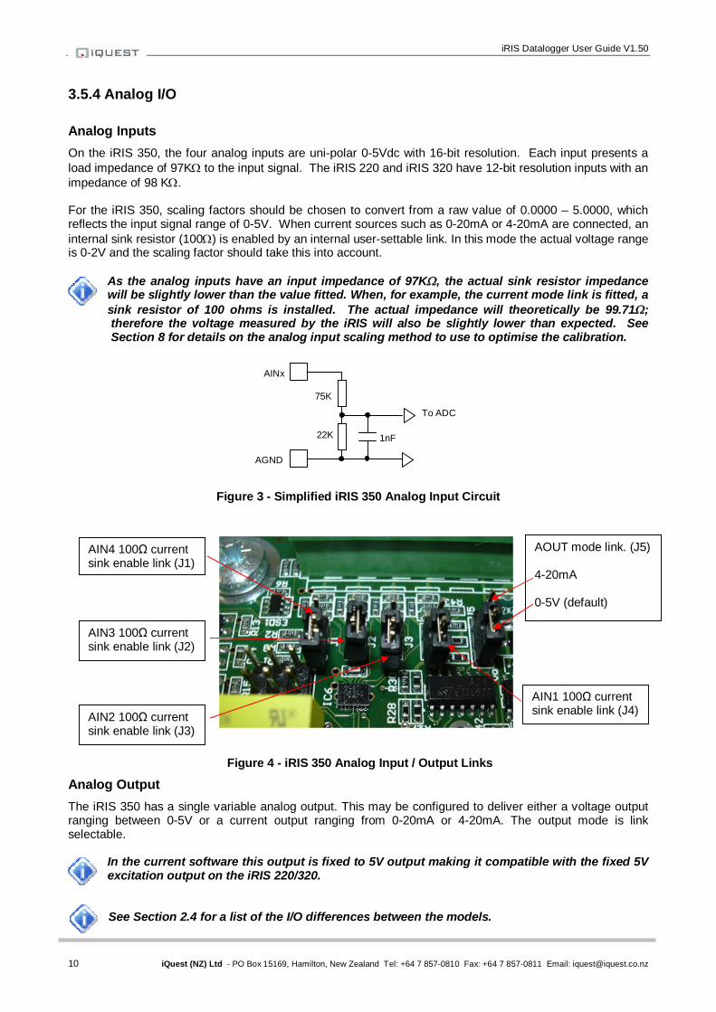
3.5.4 Analog I/O Analog Inputs On the iRIS 350, the four analog inputs are uni-polar 0-5Vdc with 16-bit resolution. Each input presents a load impedance of 97K to the input signal. The iRIS 220 and iRIS 320 have 12-bit resolution inputs with an impedance of 98 K. For the iRIS 350, scaling factors should be chosen to convert from a raw value of 0.0000 – 5.0000, which reflects the input signal range of 0-5V. When current sources such as 0-20mA or 4-20mA are connected, an internal sink resistor (100) is enabled by an internal user-settable link. In this mode the actual voltage range is 0-2V and the scaling factor should take this into account.
As the analog inputs have an input impedance of 97K, the actual sink resistor impedance will be slightly lower than the value fitted. When, for example, the current mode link is fitted, a sink resistor of 100 ohms is installed. The actual impedance will theoretically be 99.71; therefore the voltage measured by the iRIS will also be slightly lower than expected. See Section 8 for details on the analog input scaling method to use to optimise the calibration.
Figure 3 - Simplified iRIS 350 Analog Input Circuit
Figure 4 - iRIS 350 Analog Input / Output Links
Analog Output The iRIS 350 has a single variable analog output. This may be configured to deliver either a voltage output ranging between 0-5V or a current output ranging from 0-20mA or 4-20mA. The output mode is link selectable.
In the current software this output is fixed to 5V output making it compatible with the fixed 5V excitation output on the iRIS 220/320. See Section 2.4 for a list of the I/O differences between the models.
1nF 22K
75K
AGND
AINx
To ADC
AIN4 100Ω current sink enable link (J1)
AIN1 100Ω current sink enable link (J4)
AIN3 100Ω current sink enable link (J2)
AIN2 100Ω current sink enable link (J3)
AOUT mode link. (J5) 4-20mA 0-5V (default)

11 iQuest (NZ) Ltd - PO Box 15169, Hamilton, New Zealand Tel: +64 7 857-0810 Fax: +64 7 857-0811 Email: [email protected]
3.5.5 Digital I/O On the iRIS 220/iRIS 320 the I/O functions are fixed in hardware as two inputs and two outputs. The iRIS 350 has four digital I/O channels which can each be potentially configured as either an input or output. When set as an output, the channel can either supply switched 12V or else act as a pull-down switch for loads with a different supply voltage.
iRIS 350. The I/O channels have been fixed in modes that make the iRIS 350 emulate the earlier iRIS 220/320 model. Future versions will enable all the I/O features built into the hardware. For the emulated mode, these are the channel allocations: DIO1 = DI1, DIO2 = DI2, DIO3=DOUT1, DIO4=DOUT2
Digital Inputs The digital inputs are selectable for either mechanical or electronic operation. In either case it is necessary to pull the input down to 0Vdc to activate it. Inputs will handle up to 30Vdc in the off state for parallel connection across existing equipment. The “debounce” is enabled by a jumper link, which if fitted enables a longer time constant circuit to eliminate multiple pulses caused by contact bounce. The debounce jumpers are positioned in the centre of the PCB on the iRIS 350 and the right hand eedge on the iRIS 220/320.
iRIS 220/320 - The top jumper is Digital Input #2 and the bottom jumper is Digital Input #1. iRIS 350 - The top jumper is Digital I/O #4 and the bottom jumper is Digital I/O #1.
Fit the jumper for mechanical switching at up to 20Hz. In this mode the input is normally pulled up to 12V through a 10K resistor providing a wetting current of approximately 1.2mA. A 100nF capacitor is also fitted across the input to provide limited hardware debounce, preventing false triggering due to contact bounce. For installations that do not have an external power source it is important that the input is not held low for a prolonged period of time, as this will increase the current drawn from the internal battery. Remove the appropriate jumper for electronic switching at up to 5kHz. In this mode the input is normally pulled up to 5V through a 57K resistance, providing a wetting current of approximately 100A.
Figure 5 - Digital Input Circuit
IMPORTANT NOTE!
In almost all installations where an iRIS is connected in parallel with other equipment to share a common pulse input (e.g. from a flow meter), there has not been a detrimental effect, as the iRIS inputs present a relatively high impedance to the circuit. However, in the event that connecting an iRIS does cause pulse failure, iQuest recommend removing the debounce selection link for the appropriate input. This sets the input to electronic switching mode, even if the actual pulse source is a clean contact (reed switch or similar). The debounce jumpers are located on the right edge of the PCB (iRIS 220/320) or in the centre of the PCB (iRIS 350) and can be accessed once the front cover is opened. Hint: When removing a jumper, simply fit it to one pin only of the connector to avoid it being lost.
DIOx
DGND
100nF
JPx
1K 10K
+12V 5V
1nF
47K
To internal logic circuitry

iRIS Datalogger User Guide V1.50
12 iQuest (NZ) Ltd - PO Box 15169, Hamilton, New Zealand Tel: +64 7 857-0810 Fax: +64 7 857-0811 Email: [email protected]
Figure 6 - iRIS 220 / iRIS320 Digital Input Debounce Links
Figure 7 - iRIS 350 Digital I/O Debounce Links
Digital Outputs When an iRIS 350 digital I/O channel is configured as an output it can be operated in one of two ways. Open-drain pull-down capable of sinking up to 100mA at 30Vdc. An integral diode provides transient protection. Typically this output mode can be used to drive a relay or lamp powered by an auxiliary d.c supply (e.g. 12V). In this mode, the negative of the load supply must be connected to one of the iRIS GND terminals.
Although it may appear possible to directly control sensors by switching the sensor negative supply lead using Digital Output 1 (DIO3 on the iRIS 350), this will introduce measurement errors and may possibly damage the sensor. Always use Digital Output 2 (DIO4 on the iRIS 350) to power sensors on a timed basis.
Switched 12V output capable of sourcing up to 100mA. Typically this output mode will be used to drive a sensor, relay or lamp powered by the iRIS 12V supply.
Care should be taken to avoid the load discharging the internal and/or external 12V battery. Ensure adequate power supply charging capacity is available to cater for the demands of both
the logger and load. For all models, the digital outputs may be programmed to follow the state of the IP connection so that they will be active when a wireless IP session has been established. This mode can be used to control power to an external data radio when using the iRIS as a radio based gateway. Alternatively, the outputs can also be programmed to follow a schedule for use in powering loads. When configured to use the scheduled mode, the two outputs have a secondary function.
DI1 debounce link
DI2 debounce link
DIO4 debounce link
DIO1 debounce link

13 iQuest (NZ) Ltd - PO Box 15169, Hamilton, New Zealand Tel: +64 7 857-0810 Fax: +64 7 857-0811 Email: [email protected]
In scheduled mode, the relevant output(s) will be activated when a user is logged on to allow sensor calibration or radio communication testing.
DIO3 (DO1 in iRIS 320 emulation) is used to control an external radio or communication device via an I/O port or relay
DIO4 (DO2 in iRIS 320 emulation) is used for controlling external sensor(s) by applying switched 12V.
Alternatively they can be selected for remote control directly from a HydroTel™ base station, activation is any alarm is active in the iRIS or to operate in response to absolute setpoints against the current sensor value on Sensor #1 for applications such as triggering sediment samplers. See Section 4.4.11 for details on the digital output modes.
Figure 8 - Digital Output Pull-Down Mode Circuit
Figure 9 - Digital Output Switched 12V Mode Circuit
DOUT1
DGND
DOUT2
+12V
DGND
iRIS Datalogger User Guide V1.50
14 iQuest (NZ) Ltd - PO Box 15169, Hamilton, New Zealand Tel: +64 7 857-0810 Fax: +64 7 857-0811 Email: [email protected]
4 Configuration
The iRIS configuration is achieved through the connection of a terminal to the internal RS232 serial port. Most of the terminal functions are also available remotely via a UDP terminal session on GPRS models. Upon detection of a terminal connection when the RS223 port DSR signal becomes active, the iRIS will output the main configuration menu to the terminal screen. The following sections describe how to set up a terminal connection and all the menu options that are available while connected. The description assumes a computer running the Microsoft® Windows® operating system is being used and all examples relate to the standard Windows® terminal emulator application, HyperTerminal™.
iQuest provides “iLink”, which is a support utility for configuring the iQuest range of dataloggers. This includes a terminal emulator that is similar in function to HyperTerminal®. iLink is available from the iQuest website.
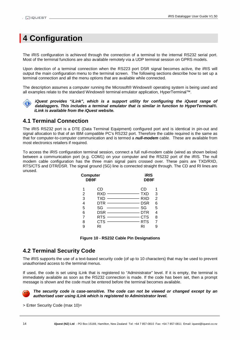
4.1 Terminal Connection The iRIS RS232 port is a DTE (Data Terminal Equipment) configured port and is identical in pin-out and signal allocation to that of an IBM compatible PC’s RS232 port. Therefore the cable required is the same as that for computer-to-computer communication and is termed a null-modem cable. These are available from most electronics retailers if required. To access the iRIS configuration terminal session, connect a full null-modem cable (wired as shown below) between a communication port (e.g. COM1) on your computer and the RS232 port of the iRIS. The null modem cable configuration has the three main signal pairs crossed over. These pairs are TXD/RXD, RTS/CTS and DTR/DSR. The signal ground (SG) line is connected straight through. The CD and RI lines are unused.
Computer iRIS DB9F DB9F
1 CD CD 1 2 RXD TXD 3 3 TXD RXD 2 4 DTR DSR 6 5 SG SG 5 6 DSR DTR 4 7 RTS CTS 8 8 CTS RTS 7 9 RI RI 9
Figure 10 - RS232 Cable Pin Designations
4.2 Terminal Security Code The iRIS supports the use of a text-based security code (of up to 10 characters) that may be used to prevent unauthorised access to the terminal menus. If used, the code is set using iLink that is registered to “Administrator” level. If it is empty, the terminal is immediately available as soon as the RS232 connection is made. If the code has been set, then a prompt message is shown and the code must be entered before the terminal becomes available.
The security code is case-sensitive. The code can not be viewed or changed except by an authorised user using iLink which is registered to Administrator level.
> Enter Security Code (max 10)=
15 iQuest (NZ) Ltd - PO Box 15169, Hamilton, New Zealand Tel: +64 7 857-0810 Fax: +64 7 857-0811 Email: [email protected]
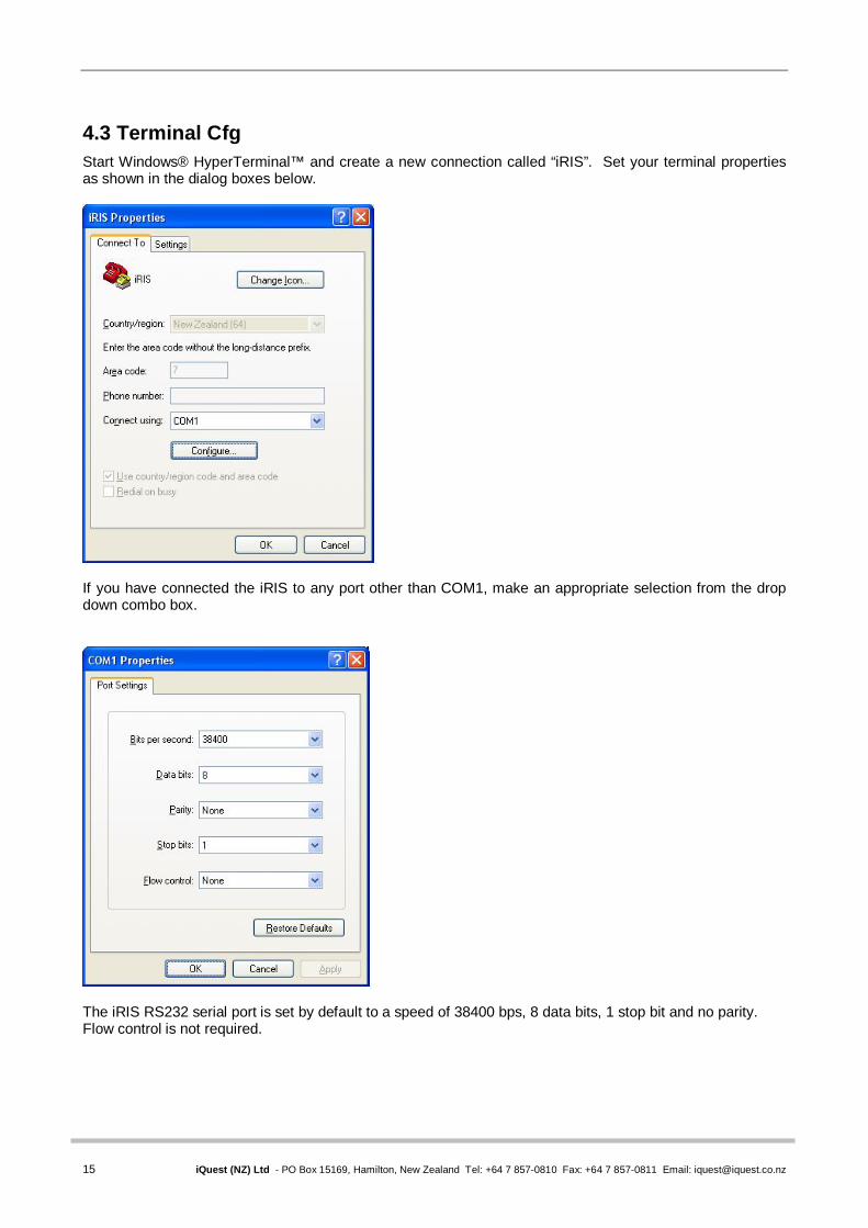
4.3 Terminal Cfg Start Windows® HyperTerminal™ and create a new connection called “iRIS”. Set your terminal properties as shown in the dialog boxes below.
If you have connected the iRIS to any port other than COM1, make an appropriate selection from the drop down combo box.
The iRIS RS232 serial port is set by default to a speed of 38400 bps, 8 data bits, 1 stop bit and no parity. Flow control is not required.
iRIS Datalogger User Guide V1.50
16 iQuest (NZ) Ltd - PO Box 15169, Hamilton, New Zealand Tel: +64 7 857-0810 Fax: +64 7 857-0811 Email: [email protected]
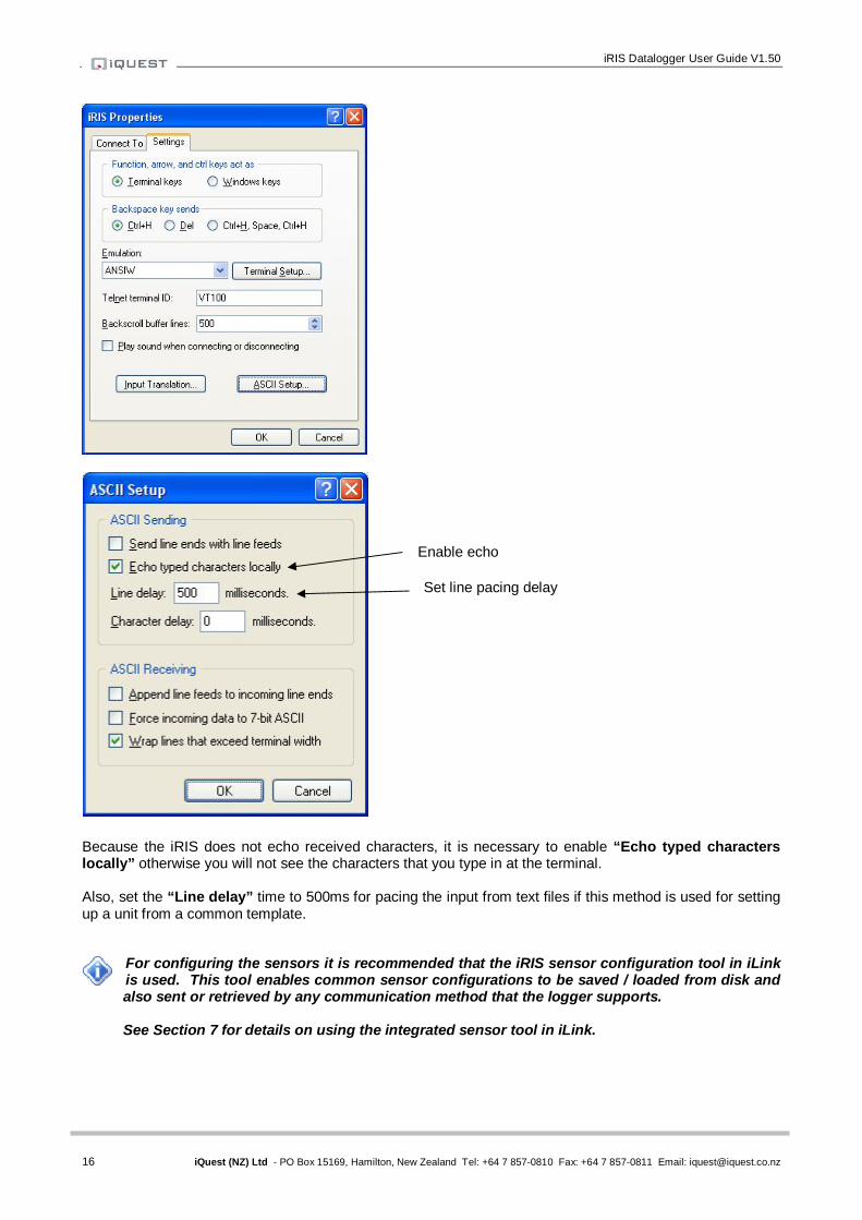
Because the iRIS does not echo received characters, it is necessary to enable “Echo typed characters locally” otherwise you will not see the characters that you type in at the terminal. Also, set the “Line delay” time to 500ms for pacing the input from text files if this method is used for setting up a unit from a common template.
For configuring the sensors it is recommended that the iRIS sensor configuration tool in iLink is used. This tool enables common sensor configurations to be saved / loaded from disk and also sent or retrieved by any communication method that the logger supports. See Section 7 for details on using the integrated sensor tool in iLink.
Enable echo
Set line pacing delay
17 iQuest (NZ) Ltd - PO Box 15169, Hamilton, New Zealand Tel: +64 7 857-0810 Fax: +64 7 857-0811 Email: [email protected]
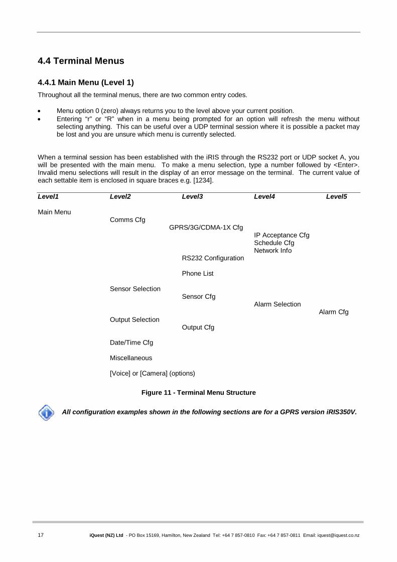
4.4 Terminal Menus 4.4.1 Main Menu (Level 1) Throughout all the terminal menus, there are two common entry codes. Menu option 0 (zero) always returns you to the level above your current position. Entering “r” or “R” when in a menu being prompted for an option will refresh the menu without
selecting anything. This can be useful over a UDP terminal session where it is possible a packet may be lost and you are unsure which menu is currently selected.
When a terminal session has been established with the iRIS through the RS232 port or UDP socket A, you will be presented with the main menu. To make a menu selection, type a number followed by <Enter>. Invalid menu selections will result in the display of an error message on the terminal. The current value of each settable item is enclosed in square braces e.g. [1234]. Level1 Level2 Level3 Level4 Level5 Main Menu
Comms Cfg GPRS/3G/CDMA-1X Cfg
IP Acceptance Cfg Schedule Cfg Network Info
RS232 Configuration
Phone List
Sensor Selection Sensor Cfg
Alarm Selection Alarm Cfg
Output Selection Output Cfg Date/Time Cfg Miscellaneous [Voice] or [Camera] (options)
Figure 11 - Terminal Menu Structure
All configuration examples shown in the following sections are for a GPRS version iRIS350V.

iRIS Datalogger User Guide V1.50
18 iQuest (NZ) Ltd - PO Box 15169, Hamilton, New Zealand Tel: +64 7 857-0810 Fax: +64 7 857-0811 Email: [email protected]
4.4.2 Main Menu (Level 1) The first menu displayed is the Main Menu. From here, you can make the following choices: * iRIS 350V GPRS (AG1-0000 / F2.50 / S1.50) 1 Site Name [My Site Name] 2 Power [Full Save, Solar] 3 Comms 4 Sensors 5 Outputs 6 Date/Time [12 Jun 2009, 12:37:55, UTC +12hrs] 7 PIN Code [0001] 8 Miscellaneous 9 Voice > Option 1 - Site Name Select this option to enter a name for the site that will be displayed on the main title screen of the LCD. The maximum length of the site name is fixed at 19 characters. On the iRIS 320 this is 12 characters. Option 2 - Power When this option is selected you will be prompted to enter a number representing the power saving mode required. > Power Save (0:None 1:Partial 2:Full 3:RS232 only)= Once the power save mode has been entered, you will then be prompted to enter the power source for the charger (0 for fixed dc power supply or 1 for solar). This selects the battery charging profile the iRIS will use. > Power Source (0:DC 1:Solar)= Check the features section (Section 2.3.4) of this manual to learn more about the various power saving modes available. Option 3 - Comms Select this option to display the Comms configuration menu. Option 4 - Sensors Select this option to display the Sensor configuration menu. Option 5 - Outputs Select this option to display the Digital Output configuration menu. Option 6 – Date/Time Select this option to display the Date/Time and clock configuration menu. Option 7- PIN Code When this option is selected you will be prompted to enter a security PIN code between 0 and 9999. This PIN code is used to restrict access to specific LCD screens. If the PIN code is set to 0 (factory default) then only the four status and the totaliser (view only) LCD screens are accessible. > PIN Code= Option 8 - Miscellaneous Select this option to display the Miscellaneous configuration menu. Option 9 – Voice or Camera The Voice option is only available on the iRIS 3x0V models that are equipped for voice operation.
Select it to access the Voice configuration. See Appendix D – Voice Annunciation (iRIS 3x0V)
The Camera option is only available if the appropriate software variant is installed. Select it to access the Camera configuration menu. See Appendix E - Using an iRIS-CAM Camera
19 iQuest (NZ) Ltd - PO Box 15169, Hamilton, New Zealand Tel: +64 7 857-0810 Fax: +64 7 857-0811 Email: [email protected]
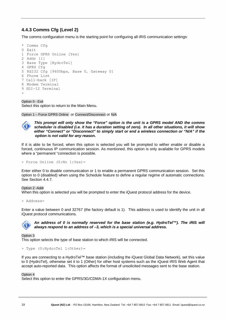
4.4.3 Comms Cfg (Level 2) The comms configuration menu is the starting point for configuring all iRIS communication settings: * Comms Cfg 0 Exit 1 Force GPRS Online [Yes] 2 Addr [1] 3 Base Type [HydroTel] 4 GPRS Cfg 5 RS232 Cfg [9600bps, Base 0, Gateway 0] 6 Phone List 7 Call-back [IP] 8 Modem Terminal 9 SDI-12 Terminal > Option 0 - Exit Select this option to return to the Main Menu. Option 1 – Force GPRS Online or Connect/Disconnect or N/A
This prompt will only show the “Force” option is the unit is a GPRS model AND the comms scheduler is disabled (i.e. it has a duration setting of zero). In all other situations, it will show either “Connect” or “Disconnect” to simply start or end a wireless connection or “N/A” if the option is not valid for any reason.
If it is able to be forced, when this option is selected you will be prompted to wither enable or disable a forced, continuous IP communication session. As mentioned, this option is only available for GPRS models where a “permanent “connection is possible. > Force Online (0:No 1:Yes)= Enter either 0 to disable communication or 1 to enable a permanent GPRS communication session. Set this option to 0 (disabled) when using the Schedule feature to define a regular regime of automatic connections. See Section 4.4.7. Option 2 -Addr When this option is selected you will be prompted to enter the iQuest protocol address for the device. > Address= Enter a value between 0 and 32767 (the factory default is 1). This address is used to identify the unit in all iQuest protocol communications.
An address of 0 is normally reserved for the base station (e.g. HydroTel™). The iRIS will always respond to an address of –3, which is a special universal address.
Option 3 This option selects the type of base station to which iRIS will be connected. > Type (0:HydroTel 1:Other)= If you are connecting to a HydroTel™ base station (including the iQuest Global Data Network), set this value to 0 (HydroTel), otherwise set it to 1 (Other) for other host systems such as the iQuest iRIS Web Agent that accept auto-reported data. This option affects the format of unsolicited messages sent to the base station. Option 4 Select this option to enter the GPRS/3G/CDMA-1X configuration menu.

iRIS Datalogger User Guide V1.50
20 iQuest (NZ) Ltd - PO Box 15169, Hamilton, New Zealand Tel: +64 7 857-0810 Fax: +64 7 857-0811 Email: [email protected]
Option 5 This option allows you to configure the RS232 port parameters. This menu is a chained input which means it prompts for multiple entries one after the other before returning to the communication menu.
These settings only apply when the iRIS has its Power Save mode set to “RS232 Only” and it is actually in Telemetry mode. Otherwise the RS232 port operates normally at 38400bps.
The first RS232 port setting field is the speed in bits per second. > RS232 Speed (0:1200,1:2400,2:4800,3:9600,4:19200,5:38400bps)= The second parameter is the address of the base station to use when calling back using the RS232 telemetry mode. The base address is normally set to zero. > Base Address=
If the unit will be expected to call back to HydroTel via a gateway site elsewhere, the base address will need to be set to a suitable value (normally the gateway setting in the gateway logger). If the base address is left set to zero, call-back will fail.
Finally, the third entry field is for the RS232 gateway offset. Use 0 to disable gateway communication. If this is not zero, then a gateway block of 100 locations is set up starting from the offset. E.g. If the gateway offset was set to 3000 then any address between 3000 and 3099 inclusive would be retransmitted back out the RS232 port with aliasing applied. > Gateway Offset=
The RS232 Only gateway mode is different to the wireless IP to RS232 bridge mode that requires a special cable to invoke. See Section 2.3.10 and RS232 Interface Telemetry for more detail on using gateway communication.
Option 6 Select this option to enter the Phone List menu. This menu enables the entering of up to two phone numbers to use as destinations for either SMS text messages or CSD dial-up call-back. Option 7 This option prompts you to enter a number representing the call-back mode for the wireless modem. This is the mode to use when the iRIS notifies an alarm notification or a test call is initiated from the keypad. > Mode (0:IP, 1:CSD, 2:SMS)= Option 8 By using this terminal mode, it is possible to perform two distinct functions depending on the state of the internal modem. If the terminal is available, this message is displayed. > Terminal Mode active. Press <ESC> and then <Enter> to exit. If the internal modem is powered down then terminal mode is unavailable and this message will appear. > Wireless module inactive. Terminal unavailable. Assuming the modem is active, the two scenarios are as follows:
If the internal modem is powered up, but an IP or CSD session is not in progress, then it is possible to interact with the modem using the standard AT command set.
If the internal modem is powered up and an IP or CSD session is currently in progress, then it is
possible to interact with a terminal at the remote end of the connection.

21 iQuest (NZ) Ltd - PO Box 15169, Hamilton, New Zealand Tel: +64 7 857-0810 Fax: +64 7 857-0811 Email: [email protected]
When using transparent terminal mode you must press the <Enter> key after each command or message you wish to send. Press ESC then Enter to exit the modem terminal session and return to the communication menu.
Option 9 The SDI-12 terminal mode allows direct access to instruments connected to the SDI-12 interface. This is useful when a manual check or changes need to be made, such as address changes, scale factors etc. Knowledge of SDI-12 commands is required to make best use of this feature. > SDI-12 Terminal mode active. Press <ESC Enter> to exit
This menu option will only appear if one or more sensors have a source set to 15 (SDI-12).
iRIS Datalogger User Guide V1.50
22 iQuest (NZ) Ltd - PO Box 15169, Hamilton, New Zealand Tel: +64 7 857-0810 Fax: +64 7 857-0811 Email: [email protected]
4.4.4 GPRS / 3G / CDMA-1X Cfg (Level 3) The GPRS/3G/CDMA-1X set-up menu configures the specific wireless IP connection settings. * GPRS Cfg 0 Exit 1 APN [iquest.co.nz] (for GPRS/3G) - Reserved – (for CDMA) 2 LogIn [,] 3 SIM PIN [0] 4 Socket A [192.168.1.10,7778] 5 Socket B [192.168.1.10,7777] 6 IP Acceptance 7 Schedule 8 GSM Module Info > Option 0 Select this option to return to the Comms Cfg menu. Option 1 When this option is selected you will be prompted to enter a GPRS or 3G APN (Access Point Name). This option is not applicable for CDMA - the menu entry will be – Reserved - and this choice will be ignored. > APN= Enter the name of the APN allocated by your network provider (e.g. iquest.co.nz). Option 2 This option is where the network login parameters (user name and password) are configured. When this option is selected you will be prompted firstly to enter a user name, then a password. Many providers do not require any login credentials, in which case these parameters should be set to empty. Press Esc then Enter to enter an empty string. > User Name= Enter the user name required by your wireless network provider. > Password= Enter the password required by your wireless network provider. Option 3 When the SIM card installed has a PIN code enabled for security purposes, use this option to define it. If a PIN code is not required, enter zero (0) for this setting.
If a SIM PIN is required and an incorrect PIN is entered, the unit will not operate correctly. For CDMA-1X units, this parameter is ignored. Also, if the SIM PIN is set incorrectly on a GPRS unit, repeated attempts by the iRIS to log-on may result in the SIM card becoming locked out. This situation will require knowledge of the SIM’s PIN Unlock Key (PUK) and/or contacting the SIM provider for unlock details.
23 iQuest (NZ) Ltd - PO Box 15169, Hamilton, New Zealand Tel: +64 7 857-0810 Fax: +64 7 857-0811 Email: [email protected]
Option 4 When this option is selected you will be prompted to enter an IP address and then a UDP or TCP port to use for Socket A. The iRIS uses Socket A for ASCII communication via UDP if it is a GPRS model. > Socket A IP= Enter the remote IP address you want to have ASCII messages delivered to/from by default. Next, you will be prompted to enter a port number to use for socket A. > Socket A Port= Enter a non-zero port number. The 3G and CDMA-1X variants do not use this socket at the present time. In these cases the settings are ignored and should be set to the same IP address and port as Socket B below. Option 5 When this option is selected you will be prompted to enter an IP address and then a UDP or TCP port to use for socket B. Socket B is the socket that is used by the iRIS for iQuest protocol (binary) communication. This is the destination IP address used for unsolicited binary calls and must be configured. > Socket B IP= Enter the remote IP address that you will connect to. Next, you will be prompted to enter a port number to use for socket B. > Socket B Port= Enter the remote port number that you want to have iQuest protocol messages delivered to by default (e.g. 7777). For the iQuest Data Network use port 7779 or port 7780 for GPRS / CDMA-1X models and port 7781 for 3G models unless advised otherwise by iQuest. Option 6 Select this option to display the IP Acceptance set-up menu. Option 7 Select this option to display the GPRS/3G/CDMA-1XSchedule configuration menu. Option 8 Select this option to display the current network settings (GPRS/3G only) or the wireless module identification parameters for CDMA. Example information for both GPRS and CDMA variants is as follows:
GPRS / 3G IMSI: 530011100721422 IMEI: 355435000001213 L/C: 0005,143F LOC: 5 TWR: 18 ANT: 3 RSSI: 19,00 IMSI: International Mobile Subscriber Information. This is derived from the SIM card IMEI: International Mobile Equipment Identifier. This is stored in the GPRS module by iQuest during initial
calibration and setup of the iRIS and uniquely identifies the hardware by manufacturer and serial number.
L/C: Location/Cell string. This is the exact cell identification string as received from the GPRS module. This is processed by the iRIS, which extracts and displays in the information in the next three parameters. The exact nature of these may vary depending on the country and network provider.

iRIS Datalogger User Guide V1.50
24 iQuest (NZ) Ltd - PO Box 15169, Hamilton, New Zealand Tel: +64 7 857-0810 Fax: +64 7 857-0811 Email: [email protected]
LOC: The Location ID of the cell that the iRIS is registered with. TWR: The Tower ID of the cell that the iRIS is registered with. ANT: The Antenna ID of the cell that the iRIS is registered with. RSSI: This displays the Received Signal Strength Indication (RSSI) followed by the Bit Error Rate (BER).
This is useful for determining the strength and quality of the signal. The possible range of values for RSSI on the GPRS or CDMA models is 0-31, with 31 being the strongest possible. A value of 99 indicates that the RSSI value is not available. In the case of 3G models, the RSSI is available as a true signal strength value in dBm.
The iRIS will not attempt to connect to the network if the RSSI is 0 or 99 on any model.
The BER gives an indication of the signal’s quality. Zero is the best (lowest error rate). The BER parameter is only applicable on GPRS models.
CDMA
ESN: ABC123 MDN: 12345678901234 RSSI: 19 ESN: Electronic Serial Number. This uniquely identifies the wireless module on the network. MDN: Mobile Data Number. This number is supplied by the service provider. It is the number used to call
the module and also to identify it on incoming or outgoing SMS text messages. RSSI: This displays the Received Signal Strength Indication (RSSI). Unlike the GPRS version, the CDMA
version does not display a BER (Bit Error Rate) parameter. 4.4.5 Phone List (Level 3) The Phone List menu is the place to configure your primary and secondary phone numbers for SMS text messaging or CSD dial-up initiated by the iRIS. These numbers are only applicable when the Call-back mode is set to 1 (CSD) or 2 (SMS). See the description of the call-back mode, Option 6 in Section 4.4.3. * Phone List 0 Exit 1 Pri Phone No [+6478570810] 2 Sec Phone No [+6478570811] > Option 0 Select this option to return to the Comms Cfg menu. Option 1 When this option is selected you will be prompted to enter the primary SMS or CSD phone number. > Pri Phone No= Enter the number of the main cellphone that will receive iRIS initiated text messages (SMS mode) or a primary telephone number of the base station that the iRIS should call when initiating dial-up communications (CSD mode). In the case of landline numbers, as the call is being made over a cellular network, the full STD prefix must be included even if the call is “local”. Option 2 When this option is selected you will be prompted to enter the secondary SMS or CSD phone number. > Sec Phone No= Enter the number of a second cellphone that will also receive iRIS initiated text messages (SMS mode) or a secondary telephone number of the base station that the iRIS should call when initiating dial-up communications (CSD mode). In the case of landline numbers, because the call is being made over a cellular network, the full STD prefix must be included even if the call is “local”.
25 iQuest (NZ) Ltd - PO Box 15169, Hamilton, New Zealand Tel: +64 7 857-0810 Fax: +64 7 857-0811 Email: [email protected]
4.4.6 IP Acceptance Cfg (Level 4) The IP acceptance set-up menu is the place to configure your IP address acceptance list.
The iRIS will always respond to messages from the IP addresses programmed for socket A and socket B since these are the defaults used for unsolicited calls. If your unit is connected to the iQuest APN and you would like iQuest to have access to the device for maintenance and support purposes, enter the iQuest Host IP Address (192.168.1.10) into one of the table entries – the default place for this address is entry 5. See Appendix I - Network Settings for iQuest APN or iQuest Global Data Network for a listing of the iQuest network settings.
* IP Acceptance Cfg 0 Exit 1 IP #1 [0.0.0.0] 2 IP #2 [0.0.0.0] 3 IP #3 [0.0.0.0] 4 IP #4 [0.0.0.0] 5 IP #5 [0.0.0.0] > Option 0 Select this option to return to the GPRS/3G/CDMA-1X set-up menu. Options 1 - 5 Select any of these options to enter the IP address of host #1 – host #5 respectively. 4.4.7 IP Connection Schedule Cfg (Level 4) The schedule set-up menu is provided to configure the wireless communication schedule. Normally this is used for wireless IP connections but can alternatively be used to send regular SMS messages to the phone number(s) in the Phone List. See Section 4.4.5 above.
If the Call-back mode (Option 6 in Section 4.4.3) is set to 2 (CSD), then this schedule has no effect.
* Schedule Cfg 0 Exit 1 Duration [300sec] 2 Frequency [60min] 3 Start Time [0600] 4 End Time [1800] 5 Send when [0 samples] 6 Data Format [Samples only] > Option 0 Select this option to return to the Comms Cfg menu. Option 1 When this option is selected you will be prompted to enter the length of time in seconds that you want the iRIS to keep each wireless IP session active. > Duration (sec)= Enter a value of 0 if you want to maintain a continuous wireless IP session. This mode should only be used in applications where a static IP address has been issued for the unit. Option 2 When this option is selected, you will be prompted to enter the length of time in minutes between each successive wireless IP session being established or an SMS message being sent. > Frequency (min)=
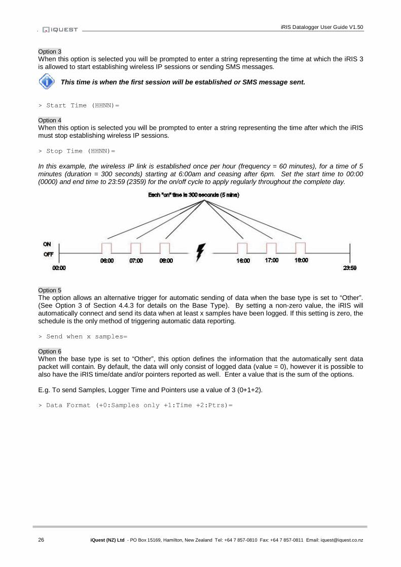
iRIS Datalogger User Guide V1.50
26 iQuest (NZ) Ltd - PO Box 15169, Hamilton, New Zealand Tel: +64 7 857-0810 Fax: +64 7 857-0811 Email: [email protected]
Option 3 When this option is selected you will be prompted to enter a string representing the time at which the iRIS 3 is allowed to start establishing wireless IP sessions or sending SMS messages.
This time is when the first session will be established or SMS message sent.
> Start Time (HHNN)= Option 4 When this option is selected you will be prompted to enter a string representing the time after which the iRIS must stop establishing wireless IP sessions. > Stop Time (HHNN)= In this example, the wireless IP link is established once per hour (frequency = 60 minutes), for a time of 5 minutes (duration = 300 seconds) starting at 6:00am and ceasing after 6pm. Set the start time to 00:00 (0000) and end time to 23:59 (2359) for the on/off cycle to apply regularly throughout the complete day.
Option 5 The option allows an alternative trigger for automatic sending of data when the base type is set to “Other”. (See Option 3 of Section 4.4.3 for details on the Base Type). By setting a non-zero value, the iRIS will automatically connect and send its data when at least x samples have been logged. If this setting is zero, the schedule is the only method of triggering automatic data reporting. > Send when x samples= Option 6 When the base type is set to “Other”, this option defines the information that the automatically sent data packet will contain. By default, the data will only consist of logged data (value = 0), however it is possible to also have the iRIS time/date and/or pointers reported as well. Enter a value that is the sum of the options. E.g. To send Samples, Logger Time and Pointers use a value of 3 (0+1+2). > Data Format (+0:Samples only +1:Time +2:Ptrs)=

27 iQuest (NZ) Ltd - PO Box 15169, Hamilton, New Zealand Tel: +64 7 857-0810 Fax: +64 7 857-0811 Email: [email protected]
4.4.8 Sensor Selection (Level 2) The Sensor Selection menu is where you select the sensor that you want to configure. From this menu, you can see at a glance which sensors are enabled for logging and if enabled, their source and name. * Sensor Cfg 0 Exit 1 Sen1 (Dis) 2 Sen2 (Dis) 3 Sen3 (Dis) 4 Sen4 (Dis) 5 Sen5 (Dis) 6 Sen6 (Dis) 7 Batt (Dis) 8 Supp (Dis) 9 Temp (Dis) > Option 0 Select this option to return to the main menu. Option 1 Select this option to display the set-up menu for Sensor 1. Option 2 Select this option to display the set-up menu for Sensor 2. Option 3 Select this option to display the set-up menu for Sensor 3. Option 4 Select this option to display the set-up menu for Sensor 4. Option 5 Select this option to display the set-up menu for Sensor 5. Option 6 Select this option to display the set-up menu for Sensor 6. Option 7 Select this option to display the set-up menu for Sensor 7 (Battery Voltage). Option 8 Select this option to display the set-up menu for Sensor 8 (Supply Voltage). Option 9 Select this option to display the set-up menu for Sensor 9 (Temperature).
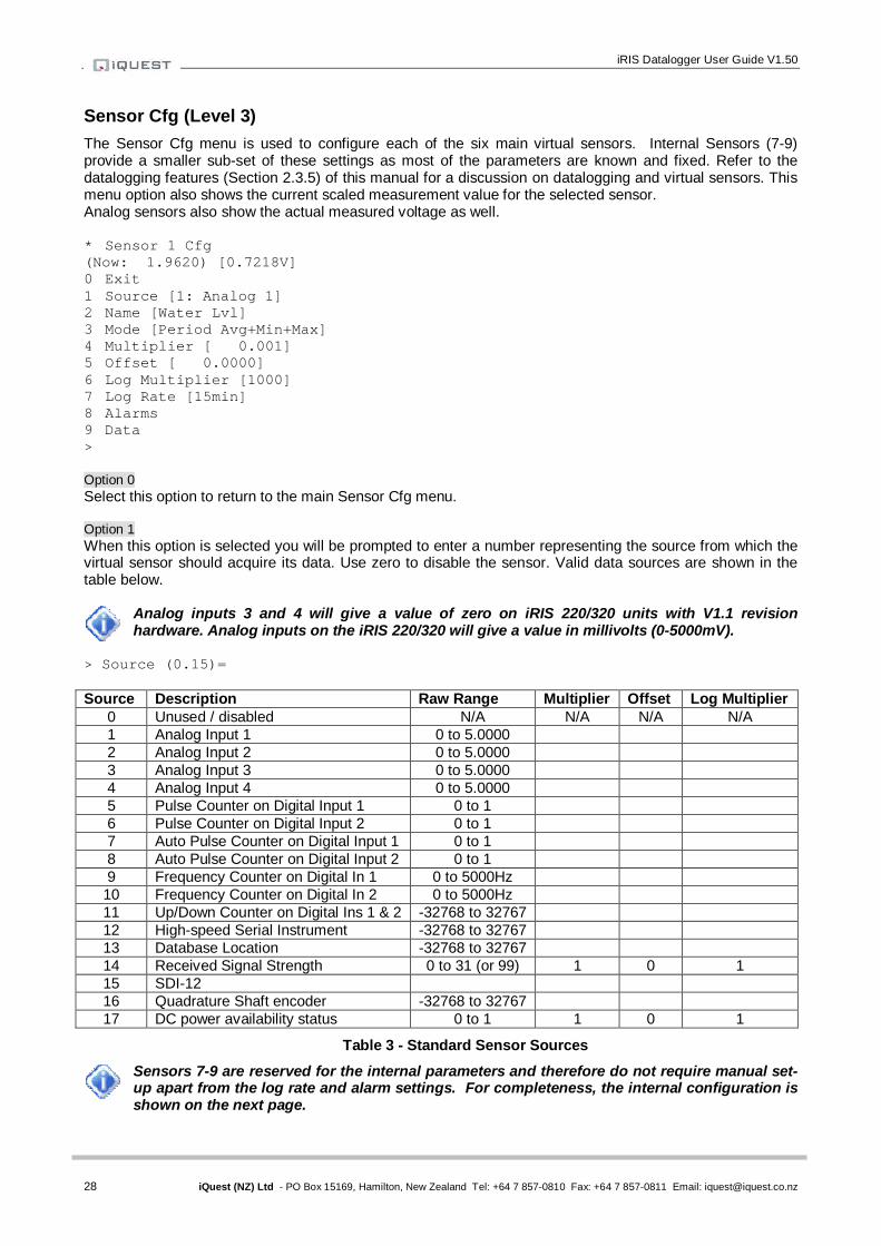
iRIS Datalogger User Guide V1.50
28 iQuest (NZ) Ltd - PO Box 15169, Hamilton, New Zealand Tel: +64 7 857-0810 Fax: +64 7 857-0811 Email: [email protected]
Sensor Cfg (Level 3) The Sensor Cfg menu is used to configure each of the six main virtual sensors. Internal Sensors (7-9) provide a smaller sub-set of these settings as most of the parameters are known and fixed. Refer to the datalogging features (Section 2.3.5) of this manual for a discussion on datalogging and virtual sensors. This menu option also shows the current scaled measurement value for the selected sensor. Analog sensors also show the actual measured voltage as well. * Sensor 1 Cfg (Now: 1.9620) [0.7218V] 0 Exit 1 Source [1: Analog 1] 2 Name [Water Lvl] 3 Mode [Period Avg+Min+Max] 4 Multiplier [ 0.001] 5 Offset [ 0.0000] 6 Log Multiplier [1000] 7 Log Rate [15min] 8 Alarms 9 Data > Option 0 Select this option to return to the main Sensor Cfg menu. Option 1 When this option is selected you will be prompted to enter a number representing the source from which the virtual sensor should acquire its data. Use zero to disable the sensor. Valid data sources are shown in the table below.
Analog inputs 3 and 4 will give a value of zero on iRIS 220/320 units with V1.1 revision hardware. Analog inputs on the iRIS 220/320 will give a value in millivolts (0-5000mV).
> Source (0.15)= Source Description Raw Range Multiplier Offset Log Multiplier
0 Unused / disabled N/A N/A N/A N/A 1 Analog Input 1 0 to 5.0000 2 Analog Input 2 0 to 5.0000 3 Analog Input 3 0 to 5.0000 4 Analog Input 4 0 to 5.0000 5 Pulse Counter on Digital Input 1 0 to 1 6 Pulse Counter on Digital Input 2 0 to 1 7 Auto Pulse Counter on Digital Input 1 0 to 1 8 Auto Pulse Counter on Digital Input 2 0 to 1 9 Frequency Counter on Digital In 1 0 to 5000Hz
10 Frequency Counter on Digital In 2 0 to 5000Hz 11 Up/Down Counter on Digital Ins 1 & 2 -32768 to 32767 12 High-speed Serial Instrument -32768 to 32767 13 Database Location -32768 to 32767 14 Received Signal Strength 0 to 31 (or 99) 1 0 1 15 SDI-12 16 Quadrature Shaft encoder -32768 to 32767 17 DC power availability status 0 to 1 1 0 1
Table 3 - Standard Sensor Sources
Sensors 7-9 are reserved for the internal parameters and therefore do not require manual set-up apart from the log rate and alarm settings. For completeness, the internal configuration is shown on the next page.
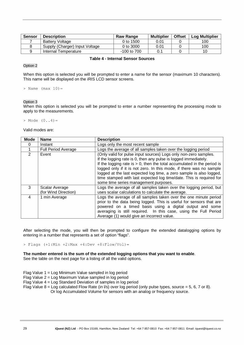
29 iQuest (NZ) Ltd - PO Box 15169, Hamilton, New Zealand Tel: +64 7 857-0810 Fax: +64 7 857-0811 Email: [email protected]
Sensor Description Raw Range Multiplier Offset Log Multiplier
7 Battery Voltage 0 to 1500 0.01 0 100 8 Supply (Charger) Input Voltage 0 to 3000 0.01 0 100 9 Internal Temperature -100 to 700 0.1 0 10
Table 4 - Internal Sensor Sources
Option 2 When this option is selected you will be prompted to enter a name for the sensor (maximum 10 characters). This name will be displayed on the iRIS LCD sensor screens. > Name (max 10)= Option 3 When this option is selected you will be prompted to enter a number representing the processing mode to apply to the measurements. > Mode (0..4)= Valid modes are: Mode Name Description
0 Instant Logs only the most recent sample 1 Full Period Average Logs the average of all samples taken over the logging period 2 Event (Only valid for pulse input sources) Logs only non-zero samples.
If the logging rate is 0, then any pulse is logged immediately. If the logging rate is > 0, then the total accumulated in the period is logged only if it is not zero. In this mode, if there was no sample logged at the last expected log time, a zero sample is also logged, time stamped with last expected log time/date. This is required for some time series management purposes.
3 Scalar Average (for Wind Direction)
Logs the average of all samples taken over the logging period, but uses scalar calculations to calculate the average.
4 1 min Average Logs the average of all samples taken over the one minute period prior to the data being logged. This is useful for sensors that are powered on a timed basis using a digital output and some averaging is still required. In this case, using the Full Period Average (1) would give an incorrect value.
After selecting the mode, you will then be prompted to configure the extended datalogging options by entering in a number that represents a set of option “flags”. > Flags (+1:Min +2:Max +4:Dev +8:Flow/Vol)= The number entered is the sum of the extended logging options that you want to enable. See the table on the next page for a listing of all the valid options. Flag Value 1 = Log Minimum Value sampled in log period Flag Value 2 = Log Maximum Value sampled in log period Flag Value 4 = Log Standard Deviation of samples in log period Flag Value 8 = Log calculated Flow Rate (in l/s) over log period (only pulse types, source = 5, 6, 7 or 8). Or log Accumulated Volume for sensors with an analog or frequency source.

iRIS Datalogger User Guide V1.50
30 iQuest (NZ) Ltd - PO Box 15169, Hamilton, New Zealand Tel: +64 7 857-0810 Fax: +64 7 857-0811 Email: [email protected]
Flag Value Description 0 No additional logging 1 Log Minimum 2 Log Maximum 3 Log Minimum and Maximum 4 Log Standard Deviation 5 Log Minimum and Standard Deviation 6 Log Maximum and Standard Deviation 7 Log Minimum, Maximum and Standard Deviation 8 Log Flow Rate or Accumulated Volume 9 Log Minimum and Flow Rate or Accumulated Volume 10 Log Maximum and Flow Rate or Accumulated Volume 11 Log Minimum, Maximum and Flow Rate or Accumulated Volume 12 Log Standard Deviation and Flow Rate or Accumulated Volume 13 Log Minimum, Standard Deviation and Flow Rate or Accumulated Volume 14 Log Maximum, Standard Deviation and Flow Rate or Accumulated Volume 15 Log Minimum, Maximum, Standard Deviation and Flow Rate or Accumulated Volume
Table 5 - Supplementary Logging Flag Definitions
Option 4 When this option is selected you will be prompted to enter a scaling multiplier. This multiplier is used to convert the raw input into engineering units. It is the “m” variable in the y=mx+c scaling equation. > Multiplier= Option 5 When this option is selected you will be prompted to enter a scaling offset. This offset is added to the scaled engineering value. It is the “c” variable in the y=mx+c scaling equation. > Offset= Option 6 When this option is selected you will be prompted to enter a logging multiplier to convert from engineering units to an integer value for storage in the logging memory. > Log Multiplier=
For example, if you need to log a measurement that has a resolution of two decimal places, you will need to enter a logging multiplier of 100.
IMPORTANT NOTE: Care needs to be taken in the selection of an appropriate logging multiplier because the iRIS stores data as signed 16-bit integer values (range from -32768 to 32767). This means that the maximum scaled value multiplied by the logging multiplier must not exceed 32767. If it does, the values will limit at that point and data will be lost.
Option 7 When this option is selected you will be prompted to enter a logging rate (in minutes) for the sensor. > Log Rate= If you wish to log digital data in true event (change of state) mode you can enter a value of 0 for this setting.
If this parameter is left set to 0 for any non-pulse type source, then it will not be logged.
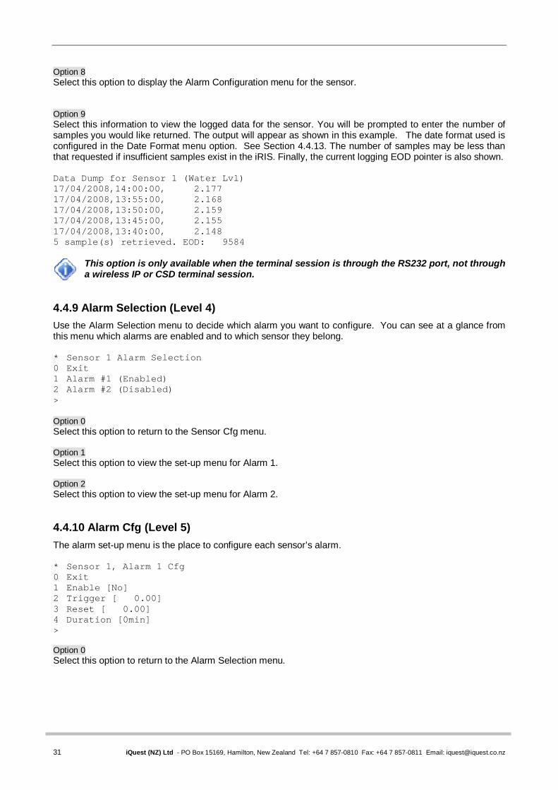
31 iQuest (NZ) Ltd - PO Box 15169, Hamilton, New Zealand Tel: +64 7 857-0810 Fax: +64 7 857-0811 Email: [email protected]
Option 8 Select this option to display the Alarm Configuration menu for the sensor. Option 9 Select this information to view the logged data for the sensor. You will be prompted to enter the number of samples you would like returned. The output will appear as shown in this example. The date format used is configured in the Date Format menu option. See Section 4.4.13. The number of samples may be less than that requested if insufficient samples exist in the iRIS. Finally, the current logging EOD pointer is also shown. Data Dump for Sensor 1 (Water Lvl) 17/04/2008,14:00:00, 2.177 17/04/2008,13:55:00, 2.168 17/04/2008,13:50:00, 2.159 17/04/2008,13:45:00, 2.155 17/04/2008,13:40:00, 2.148 5 sample(s) retrieved. EOD: 9584
This option is only available when the terminal session is through the RS232 port, not through a wireless IP or CSD terminal session.
4.4.9 Alarm Selection (Level 4) Use the Alarm Selection menu to decide which alarm you want to configure. You can see at a glance from this menu which alarms are enabled and to which sensor they belong. * Sensor 1 Alarm Selection 0 Exit 1 Alarm #1 (Enabled) 2 Alarm #2 (Disabled) > Option 0 Select this option to return to the Sensor Cfg menu. Option 1 Select this option to view the set-up menu for Alarm 1. Option 2 Select this option to view the set-up menu for Alarm 2. 4.4.10 Alarm Cfg (Level 5) The alarm set-up menu is the place to configure each sensor’s alarm. * Sensor 1, Alarm 1 Cfg 0 Exit 1 Enable [No] 2 Trigger [ 0.00] 3 Reset [ 0.00] 4 Duration [0min] > Option 0 Select this option to return to the Alarm Selection menu.

iRIS Datalogger User Guide V1.50
32 iQuest (NZ) Ltd - PO Box 15169, Hamilton, New Zealand Tel: +64 7 857-0810 Fax: +64 7 857-0811 Email: [email protected]
Option 1 When this option is selected you will be prompted to enable/disable the alarm. > Enable (0:No 1:Yes)= Enter a value of 0 to disable the alarm. Enter a value of 1 to enable it. Option 2 When this option is selected you will be prompted to enter a trigger level for the alarm. > Trigger= Enter a value in engineering units that you want to use as the trigger point for the alarm. When the scaled value crosses this limit the alarm will become active. The trigger direction is determined by the reset level. See Option 3 below. Option 3 When this option is selected you will be prompted to enter a reset level for the alarm. > Reset= Enter a value in engineering units that you want to use as the reset point for the alarm. When the scaled value falls below this limit the alarm will be deactivated. If the reset level is set to a value greater than the trigger level then the alarm is reverse acting. This mode is normally used for low voltage or level alarms. Option 4 When this option is selected you will be prompted to enter a time in seconds to delay alarm activation. This can be used to implement alarm hysteresis for analog data sources that vary. If the data source is one of the internal counters, then this time is used to totalise individual sample values. If the total over the given alarm duration is above the trigger level then an alarm is generated. Typically this feature is used for rainfall alarms. > Duration (min)= 4.4.11 Output Selection (Level 2) The Output Selection menu is where you select the digital output you want to configure. From this menu, you can see at a glance which outputs are enabled. * Output Selection 0 Exit 1 Output #1 (Enabled) 2 Output #2 (Disabled) > Option 0 Select this option to return to the main menu. Option 1 Select this option to display the set-up menu for Output 1. Option 2 Select this option to display the set-up menu for Output 2. 4.4.12 Output Cfg (Level 3) The Output Cfg menu is used to configure each digital output. In the example below, output 1 is being configured. * Digital Output 1 Cfg 0 Exit

33 iQuest (NZ) Ltd - PO Box 15169, Hamilton, New Zealand Tel: +64 7 857-0810 Fax: +64 7 857-0811 Email: [email protected]
1 Enable [Yes] 2 Polarity [Normal] 3 Mode [Schedule] 4 Duration [30sec] 5 Frequency [1min] 6 Start Time [0000] 7 End Time [2359] > Option 0 Select this option to return to the Output Selection menu. Option 1 When this option is selected you will be prompted to enable/disable the output. > Enable (0:No 1:Yes)= Enter a value of 0 if you want to disable the output. Enter a value of 1 if you want to enable it. Option 2 When this option is selected you will be prompted to select the switching polarity of the output. This relates to the output’s electrical state with respect to its logical on/off state. If the polarity setting is 0 (normal), the output will be electrically on when the output logical state is on and be high impedance (open-circuit) when the output is logically off. If the polarity setting is 1 (inverted), the output will be high impedance (open-circuit) when the output logical state is on and be electrically on when the output is logically off. > Polarity (0:Normal 1:Inverted)= Option 3 When this option is selected you will be prompted to enter a number representing the operating mode of the output. > Mode (0..6)= Valid modes are: Source Description
0 Follow wireless link state. I.e. Output is on if communication link is on-line. 1 Follow Schedule as defined by the settings in Options 3-6 described below. 2 Remote Control from Base. DO1 is controlled by bit 0 of d1000, DO2 by bit 1 of d1000. 3 Low Trigger. Activate when Sensor 1 last logged value <= trigger setpoint and trigger enabled. 4 High Trigger. Activate when Sensor 1 last logged value >= trigger setpoint and trigger enabled. 5 Force output permanently on. Required for DO2 output if Unidata high-speed encoder used. 6 The output is on if any sensor alarm is active. Turns off when all alarms are inactive.
If DO1 is set to Mode 1 (Schedule) AND the Power Save mode is set to 3 (RS232 Only), DO1 will be forced on when an alarm requiring transmission to a base station is pending. This is to enable an external radio to be powered up in order to transmit the alarm call-in. After successful acknowledgement, the output will then remain on for the Duration configured in Option 4 below. If DO2 is set to Mode 1 (Schedule) it will be forced on while a user is logged on via the LCD/keypad interface. This is to power up controlled sensors for calibration purposes.
Option 4 When this option is selected you will be prompted to enter the length of time in seconds that you want the iRIS to keep the output energised for if the mode is set to 1 (Schedule). > Duration (sec)=

iRIS Datalogger User Guide V1.50
34 iQuest (NZ) Ltd - PO Box 15169, Hamilton, New Zealand Tel: +64 7 857-0810 Fax: +64 7 857-0811 Email: [email protected]
Option 5 When this option is selected you will be prompted to enter the length of time in minutes between the successive operations of the output if the mode is set to 1 (Schedule). > Frequency (min)= Option 6 When this option is selected you will be prompted to enter a string representing the time at which the iRIS is allowed to start controlling the output if the mode is set to 1 (Schedule). > Start Time (HHNN)= Option 7 When this option is selected you will be prompted to enter a string representing the time at which the iRIS must stop controlling the output if the mode is set to 1 (Schedule).
> End Time (HHNN)= See Section 4.4.7, titled IP Connection Schedule Cfg for details on how these parameters configure the schedule operation.
Typical Scheduled Output Example A ground water site using an iRIS is required to log a sample every hour that is obtained from a pressure transducer whose power supply is controlled from the digital output, DO2 (DIO4 on the iRIS 350) which is a switched 12V output. For early iRIS 220/320 (V1.1) boards, this output will need to be connected via an external transistor switch. The transducer needs to be powered up for one minute prior to the measurement being taken and logged. The settings required for DO2 to achieve this are shown below. * Digital Output 2 Setup 0 Exit 1 Enable [Yes] 2 Polarity [Normal] 3 Mode [Schedule] 4 Duration [65 sec] 5 Frequency [60 min] 6 Start Time [0059] 7 End Time [2359] The output will be activated at the beginning of the 59th minute of each hour in the day, starting at 00:59. It will remain on for 65 seconds, ensuring that the sensor is still powered up at the point when the reading is captured on the hour. The final output activation for the day will occur at 23:59 in preparation for the midnight measurement.
If some averaging is required, the one minute averaging (process mode 4) can be selected. However, set the scheduler to ensure that the sensor will be fully powered up before and through out the one minute before logging.

35 iQuest (NZ) Ltd - PO Box 15169, Hamilton, New Zealand Tel: +64 7 857-0810 Fax: +64 7 857-0811 Email: [email protected]
4.4.13 Date/Time Cfg (Level 2) The Date/Time Cfg menu is where the various time functions are configured. These include date, time of day, date format, time zone offset and clock trim. * Date / Time 1 Cfg 0 Exit 1 Date [04 Jun 2008] 2 Time [14:23:49] 3 Date Format [0: dd Mmm yyyy] 4 Time Offset [UTC +12hrs] 5 Clock Trim [-1] Option 1 When this option is selected you will be prompted to enter the current local date as a string containing four digits for year, two digits for month and two digits for day. All 8 digits must be entered. > Date (YYYYMMDD)= Option 2 When this option is selected you will be prompted to enter the current local time as a string containing two digits for hour, two digits for minute and two digits for second. All 6 digits must be entered. > Time (HHMMSS)= Option 3 When this option is selected you will be prompted to select the date format as used throughout the iRIS (LCD screens and terminal menus). Enter a number to select the desired format. > Date Format (0=dd Mth yyyy, 1=dd/mm/yyyy, 3=dd/mm/yy, 4=mm/dd/yyyy, 6=mm/dd/yy)=
Not all of the numbers between 0 and 6 relate to a valid format. E.g. 2 and 5. This is due to the way the iRIS uses the structure of the format code internally.
Option 4 When this option is selected you will be prompted to enter the offset of the iRIS’ local time with respect to UTC (GMT). This is used for international time correction if the data is forwarded to the iQuest Global Data Network. For example, enter +12 for NZST or –8 for PST and so on. > Time Offset= Option 5 This option prompts for a number to trim the iRIS real time clock to minimise drift which can be dependent upon the average ambient temperature of the environment in which it is installed in extreme circumstances. This value can be between –3 and +3 and is a relative index that relates approximately to the number of seconds to correct per day. It is factory set to a default value of 0, providing minimal drift at typical room temperatures. If the clock is slow (losing time), set the offset to be a positive value, or if it is fast (gaining time), set the offset to a negative value. > Trim Factor (-3 to +3) =
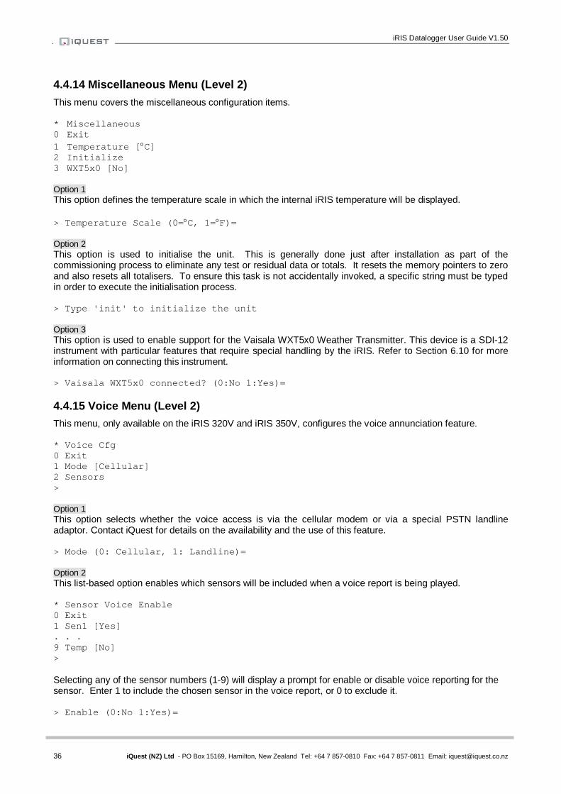
iRIS Datalogger User Guide V1.50
36 iQuest (NZ) Ltd - PO Box 15169, Hamilton, New Zealand Tel: +64 7 857-0810 Fax: +64 7 857-0811 Email: [email protected]
4.4.14 Miscellaneous Menu (Level 2) This menu covers the miscellaneous configuration items. * Miscellaneous 0 Exit 1 Temperature [C] 2 Initialize 3 WXT5x0 [No] Option 1 This option defines the temperature scale in which the internal iRIS temperature will be displayed. > Temperature Scale (0=C, 1=F)= Option 2 This option is used to initialise the unit. This is generally done just after installation as part of the commissioning process to eliminate any test or residual data or totals. It resets the memory pointers to zero and also resets all totalisers. To ensure this task is not accidentally invoked, a specific string must be typed in order to execute the initialisation process. > Type 'init' to initialize the unit Option 3 This option is used to enable support for the Vaisala WXT5x0 Weather Transmitter. This device is a SDI-12 instrument with particular features that require special handling by the iRIS. Refer to Section 6.10 for more information on connecting this instrument. > Vaisala WXT5x0 connected? (0:No 1:Yes)= 4.4.15 Voice Menu (Level 2) This menu, only available on the iRIS 320V and iRIS 350V, configures the voice annunciation feature. * Voice Cfg 0 Exit 1 Mode [Cellular] 2 Sensors > Option 1 This option selects whether the voice access is via the cellular modem or via a special PSTN landline adaptor. Contact iQuest for details on the availability and the use of this feature. > Mode (0: Cellular, 1: Landline)= Option 2 This list-based option enables which sensors will be included when a voice report is being played. * Sensor Voice Enable 0 Exit 1 Sen1 [Yes] . . . 9 Temp [No] > Selecting any of the sensor numbers (1-9) will display a prompt for enable or disable voice reporting for the sensor. Enter 1 to include the chosen sensor in the voice report, or 0 to exclude it. > Enable (0:No 1:Yes)=

37 iQuest (NZ) Ltd - PO Box 15169, Hamilton, New Zealand Tel: +64 7 857-0810 Fax: +64 7 857-0811 Email: [email protected]
5 Operation
5.1 LED Indicators The iRIS has several LED indicators. The main status LED and eight diagnostic LEDs are visible from the front of the enclosure. 5.1.1 Status LED The status LED is a tri-colour device that is used to indicate the unit status.
Status LED Indication Idle, low or no signal strength Flashes red once every three seconds Idle, adequate signal strength Flashes green once every three seconds Connecting to network Flashes blue every half a second Connected to network Flashes blue once every three seconds Failed to connect Flashes red every half a second
Table 6 - Status LED Indication Modes
5.1.2 Diagnostic LEDs The iRIS has eight LED indicators that are useful for diagnostic purposes. On the iRIS 350 these are always visible through the front of the enclosure. For the iRIS 220 and iRIS 320, the LEDs are internal and require the case to be open to make them visible.
With the exception of the SDI-12 TX LED, these indicators are only active when the power management mode is set to No Power Save (see the Features Section 2.3.4 for details on power management).
DIO1 Illuminated red when Digital I/O #1 (DI1) is active. DIO2 Illuminated red when Digital I/O #2 (DI2) is active. DIO3 Illuminated red when Digital I/O #3 (DO2) is active. DIO4 Illuminated red when Digital I/O #4 (DO2) is active. 232 RX Flashes green when data is received from the RS232 port. 232 TX Flashes green when data is transmitted out the RS232 port. Modem Flashes green when there is receive or transmit activity with the wireless modem. SDI-12 Flashes green when an SDI-12 message is transmitted or received.

iRIS Datalogger User Guide V1.50
38 iQuest (NZ) Ltd - PO Box 15169, Hamilton, New Zealand Tel: +64 7 857-0810 Fax: +64 7 857-0811 Email: [email protected]
5.2 LCD & Keypad 5.2.1 LCD Operation The iRIS LCD is controlled to optimise power consumption. If the display has powered down (in full power save mode), the unit is in the lowest power mode and can be woken by pressing any key on the keypad. After a certain period of no key presses, the display and backlight will power down again, although other functions continue normally. If the user was logged on (PIN entered), they will be logged off. This version of software has the timeout period set to 5 minutes. 5.2.2 Status Icons At the top of the LCD is a row of status icons. House Indicates current connection state as given below:
Invisible Disconnected Outline Disconnected in wireless mode Solid Connected in wireless mode Solid with ‘R’ Connected in RS232 only mode
Spanner Indicates active RS232 or UDP terminal connection.
Invisible No terminal connected Solid Terminal connected
Book Indicates transparent (modem or SDI-12) terminal mode is active
Invisible no transparency Solid transparent terminal active
Signal Indicates signal strength. Only updated when wireless modem is powered up but wireless IP session is not active.
Envelope Flashes when an unsolicited call-in is pending or in progress. This can be the result of an alarm activation or a user request for a test call-in.
Battery / Power Indicates current battery charge. The level indication bars cycle when charging is in progress. On the iRIS 350, if the unit is on an external supply a power plug icon will appear.
Padlock Indicates current access level
Invisible logged in Outline logged out Solid secure (PIN set to zero)
5.2.3 Keypad Buttons The four keypad buttons are used to navigate through the LCD screens. Their use varies depending upon the current screen in view; however the key combinations listed below are constant for all screens. Alt + Pan display right Alt - Pan display left
The display has been designed for a maximum of 24 characters per line even though the actual LCD can only display 19 characters. In the case of the iRIS 320 this is limited to 12 characters.
Using the panning function allows additional text to be viewed. This is most useful when viewing logged data samples, where the sample date and time information may be off the screen when the display is fully left.

39 iQuest (NZ) Ltd - PO Box 15169, Hamilton, New Zealand Tel: +64 7 857-0810 Fax: +64 7 857-0811 Email: [email protected]
5.2.4 Display Menu Structure The actual LCD screens that are available will depend upon the level of access that has been enabled (no access, not logged-in, or logged-in). The screens available in each mode are shown below: 1. Minimum Access (PIN code = 0, Log-in is not possible) Level 0 Level 1 Level 2 Level 3 Level 4 Level 5 Level6
Status 1 Status 2 Status 3 Status 4
Totalisers [1..2] 2. View Only Access (PIN code <> 0, but user is not logged-in) Level 0 Level 1 Level 2 Level 3 Level 4 Level 5 Level6 Log-In
Status 1 Status 2 Status 3 Status 4
Main Menu Sensors [1..9]
Sensor Menu Sensor Data
Totalisers [1..2]
Comms Status 3. Full Access (PIN code <> 0 and user is logged-in) Level 0 Level 1 Level 2 Level 3 Level 4 Level 5 Level6 Log-Out
Status 1 Status 2 Status 3 Status 4 Log Control Main Menu
Sensors [1..6] Sensor Menu Sensor Settings [1..5]
Sensor Calibration Sensor Data
Totalisers [1..2] Totalisers Reset
Comms Status Comms Menu Comms Settings [1..9] RS232 Cfg Comms Enable Comms Test
To move down a level in the menu structure, press the <Enter> key. To move up a level press the <Alt> and <Enter> keys simultaneously. You can scroll through the screens that are followed by a number in square brackets (e.g. [1..4]) by pressing the + or - keys (stepping forwards and backwards respectively).
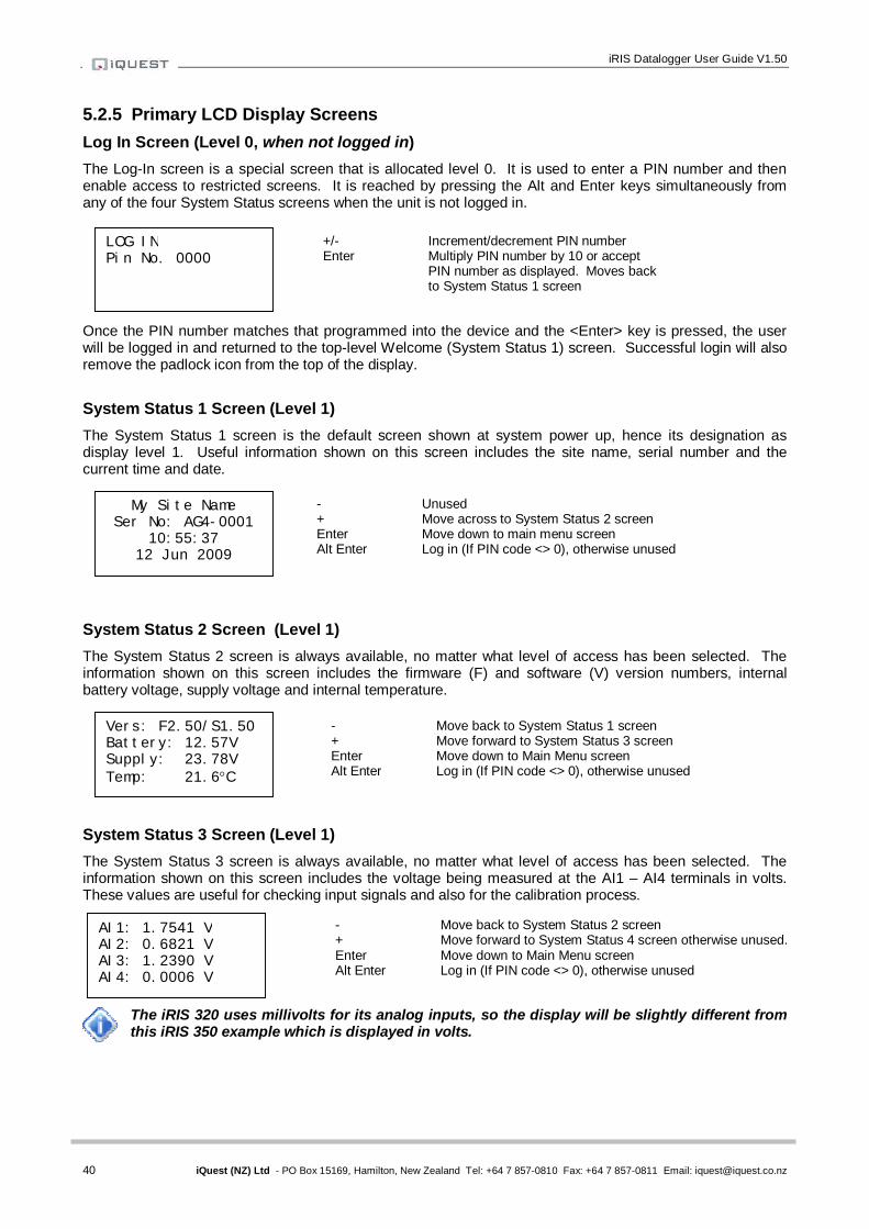
iRIS Datalogger User Guide V1.50
40 iQuest (NZ) Ltd - PO Box 15169, Hamilton, New Zealand Tel: +64 7 857-0810 Fax: +64 7 857-0811 Email: [email protected]
5.2.5 Primary LCD Display Screens Log In Screen (Level 0, when not logged in) The Log-In screen is a special screen that is allocated level 0. It is used to enter a PIN number and then enable access to restricted screens. It is reached by pressing the Alt and Enter keys simultaneously from any of the four System Status screens when the unit is not logged in.
Once the PIN number matches that programmed into the device and the <Enter> key is pressed, the user will be logged in and returned to the top-level Welcome (System Status 1) screen. Successful login will also remove the padlock icon from the top of the display. System Status 1 Screen (Level 1) The System Status 1 screen is the default screen shown at system power up, hence its designation as display level 1. Useful information shown on this screen includes the site name, serial number and the current time and date.
System Status 2 Screen (Level 1) The System Status 2 screen is always available, no matter what level of access has been selected. The information shown on this screen includes the firmware (F) and software (V) version numbers, internal battery voltage, supply voltage and internal temperature.
System Status 3 Screen (Level 1) The System Status 3 screen is always available, no matter what level of access has been selected. The information shown on this screen includes the voltage being measured at the AI1 – AI4 terminals in volts. These values are useful for checking input signals and also for the calibration process.
The iRIS 320 uses millivolts for its analog inputs, so the display will be slightly different from this iRIS 350 example which is displayed in volts.
My Site Name Ser No: AG4-0001
10:55:37 12 Jun 2009
- Unused + Move across to System Status 2 screen Enter Move down to main menu screen Alt Enter Log in (If PIN code <> 0), otherwise unused
LOG IN Pin No. 0000
+/- Increment/decrement PIN number Enter Multiply PIN number by 10 or accept
PIN number as displayed. Moves back to System Status 1 screen
Vers: F2.50/S1.50 Battery: 12.57V Supply: 23.78V Temp: 21.6C
- Move back to System Status 1 screen + Move forward to System Status 3 screen Enter Move down to Main Menu screen Alt Enter Log in (If PIN code <> 0), otherwise unused
AI1: 1.7541 V AI2: 0.6821 V AI3: 1.2390 V AI4: 0.0006 V
- Move back to System Status 2 screen + Move forward to System Status 4 screen otherwise unused. Enter Move down to Main Menu screen Alt Enter Log in (If PIN code <> 0), otherwise unused

41 iQuest (NZ) Ltd - PO Box 15169, Hamilton, New Zealand Tel: +64 7 857-0810 Fax: +64 7 857-0811 Email: [email protected]
System Status 4 Screen (Level 1) The System Status 4 screen is also always available, no matter what level of access has been selected. The information shown on this screen includes the current status of the digital inputs and outputs (0=OFF, 1=ON). This screen shows the current SOD and EOD pointer values.
Logging Control Screen (only accessible when logged in) The Logging Control screen is a special screen that is only available on level 1 when a user is logged in. It can be used to temporarily disable logging when the logged in user is making changes to or tests with sensors and does not want to have the data logged. It is reached by pressing the + key from Status Screen 4. Use the Enter key to toggle logging on or off. If the logging is disabled, it is always re-enabled automatically when the user logs out, either manually or on inactivity timeout.
Use the – or + keys to switch the logging on or off. Pressing the <Enter> key will return the display to the top-level Welcome (System Status 1) screen. Main Menu Screen (Level 2) The Main Menu screen is used to select which type of information you want to look at.
5.2.6 Sensor Related Screens Sensor Status Screen (Level 3) This screen provides an overview of each sensor. Line 1 indicates sensor ID, data source and its composite status including:
‘.’ if sensor is enabled ‘:’ if sensor and alarm(s) are enabled ‘*’ if sensor and alarm(s) are enabled and alarm(s) currently active
Line 2 indicates the raw input value. Line 3 indicates the scaled (engineering unit’s) value. Line 4 indicates the last logged value.
MAIN MENU >Sensors Totals Comms
1: Bat Volt Input: 1257 Scaled: 12.57 Logged: 12.62
+/- Move down/up through menu Enter Select menu item Alt Enter Move up to System Status 1 screen
+/- Move forwards/backwards through sensors Enter Drill down to Sensor Menu screen Alt Enter Move up to Main Menu screen
DI1:0 DI2:1 DO1:1 DO2:0 SOD Ptr: 177104 EOD Ptr: 177336
- Move back to System Status 3 screen + Move to Logging Control screen if logged in. Unused otherwise. Enter Move down to Main Menu screen Alt Enter Log in (If PIN code <> 0), otherwise unused
LOGGING CONTROL Use Enter key to Enable/disable. => Enabled
- Move back to System Status 4 screen + Unused Enter Toggle logging on or off Alt Enter Unused

iRIS Datalogger User Guide V1.50
42 iQuest (NZ) Ltd - PO Box 15169, Hamilton, New Zealand Tel: +64 7 857-0810 Fax: +64 7 857-0811 Email: [email protected]
Sensor Menu Screen (Level 4) The Sensor Menu screen is used to select sensor options.
Sensor Settings Screen 1/5 - Process (Level 5) The Sensor Process screen shows the processing mode used to convert the incoming raw data to engineering units.
Sensor Settings Screen 2/5 - Scaling (Level 5) The Sensor Scaling screen shows the multiplier and offset used to convert the incoming raw data to engineering units.
Sensor Settings Screen 3/5 - Logging (Level 5) The Sensor Logging screen shows the multiplier used when logging sensor data and the rate at which that data is logged.
Sensor Settings Screen 4/5 - Alarm 1 (Level 5) Sensor Alarm screen 1 shows the trigger and reset levels used to generate an alarm and the duration used to qualify the alarm. If the sensor gets its data from an analog input, the duration is used to provide an alarm delay. If the sensor is a pulse input counter, the logged data is totalised over the duration before comparing to the alarm trigger and reset levels.
SENSOR MENU >Settings Calibration Data
SCALING 2/5 x 0.0010 + 0.0000
LOGGING 3/5 X 00100 ∆(min) 00030
ALARM#1 4/5 / 6.3500 \ 6.5000 ∆(min) 00000
+/- Move down/up through menu Enter Select menu item Alt Enter Move up to Sensor Status screen
+/- Move forwards/backwards through sensor setting screens. Alt Enter Move up to Sensor Status screen
+/- Move forwards/backwards through sensor setting screens. Alt Enter Move up to Sensor Status screen
+/- Move forwards/backwards through sensor setting screens. Alt Enter Move up to Sensor Status screen
PROCESS 1/5 Mode Instant
+/- Move forwards/backwards through sensor setting screens. Alt Enter Move up to Sensor Status screen
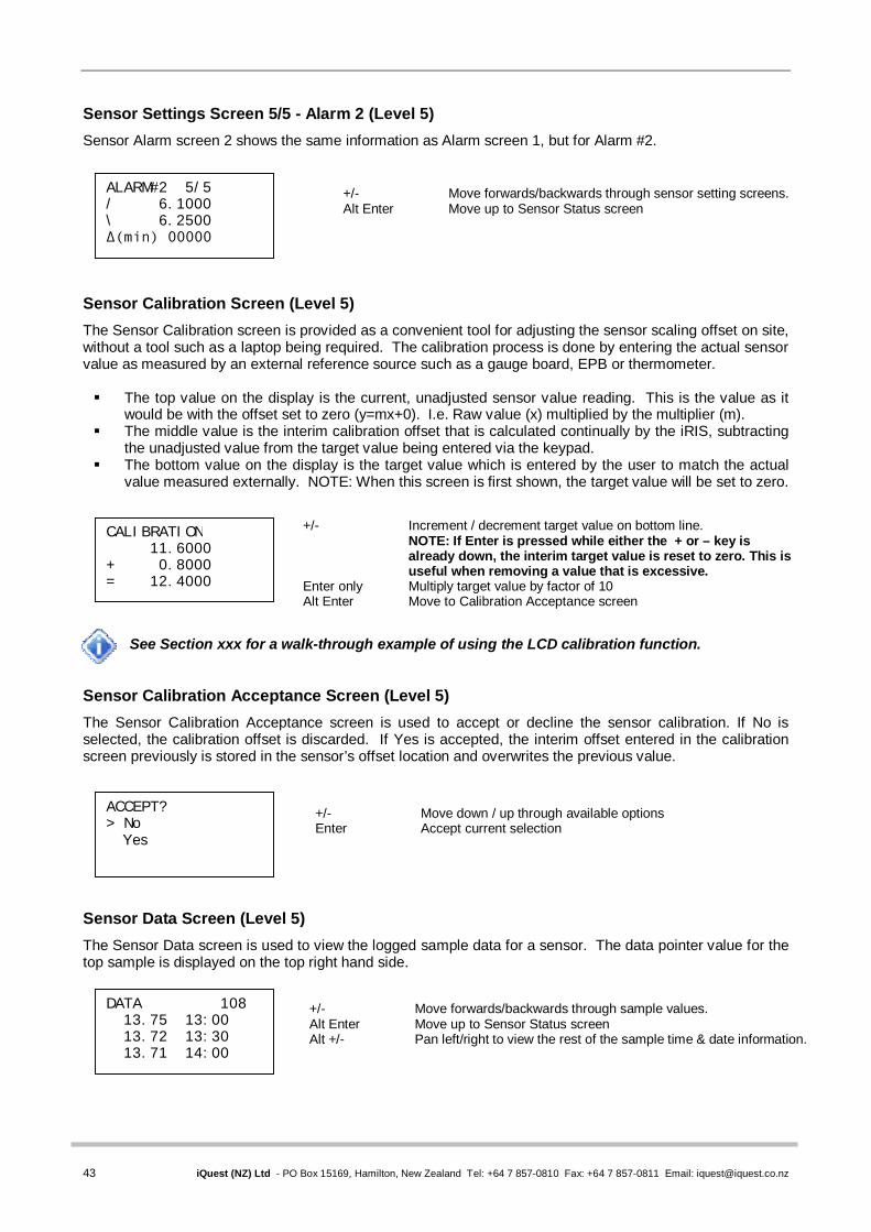
43 iQuest (NZ) Ltd - PO Box 15169, Hamilton, New Zealand Tel: +64 7 857-0810 Fax: +64 7 857-0811 Email: [email protected]
Sensor Settings Screen 5/5 - Alarm 2 (Level 5) Sensor Alarm screen 2 shows the same information as Alarm screen 1, but for Alarm #2.
Sensor Calibration Screen (Level 5) The Sensor Calibration screen is provided as a convenient tool for adjusting the sensor scaling offset on site, without a tool such as a laptop being required. The calibration process is done by entering the actual sensor value as measured by an external reference source such as a gauge board, EPB or thermometer. The top value on the display is the current, unadjusted sensor value reading. This is the value as it
would be with the offset set to zero (y=mx+0). I.e. Raw value (x) multiplied by the multiplier (m). The middle value is the interim calibration offset that is calculated continually by the iRIS, subtracting
the unadjusted value from the target value being entered via the keypad. The bottom value on the display is the target value which is entered by the user to match the actual
value measured externally. NOTE: When this screen is first shown, the target value will be set to zero.
See Section xxx for a walk-through example of using the LCD calibration function.
Sensor Calibration Acceptance Screen (Level 5) The Sensor Calibration Acceptance screen is used to accept or decline the sensor calibration. If No is selected, the calibration offset is discarded. If Yes is accepted, the interim offset entered in the calibration screen previously is stored in the sensor’s offset location and overwrites the previous value.
Sensor Data Screen (Level 5) The Sensor Data screen is used to view the logged sample data for a sensor. The data pointer value for the top sample is displayed on the top right hand side.
DATA 108 13.75 13:00 13.72 13:30 13.71 14:00
+/- Move forwards/backwards through sample values. Alt Enter Move up to Sensor Status screen Alt +/- Pan left/right to view the rest of the sample time & date information.
ALARM#2 5/5 / 6.1000 \ 6.2500 ∆(min) 00000
+/- Move forwards/backwards through sensor setting screens. Alt Enter Move up to Sensor Status screen
CALIBRATION 11.6000 + 0.8000 = 12.4000
+/- Increment / decrement target value on bottom line. NOTE: If Enter is pressed while either the + or – key is already down, the interim target value is reset to zero. This is useful when removing a value that is excessive.
Enter only Multiply target value by factor of 10 Alt Enter Move to Calibration Acceptance screen
ACCEPT? > No Yes
+/- Move down / up through available options Enter Accept current selection

iRIS Datalogger User Guide V1.50
44 iQuest (NZ) Ltd - PO Box 15169, Hamilton, New Zealand Tel: +64 7 857-0810 Fax: +64 7 857-0811 Email: [email protected]
5.2.7 Totaliser Related Screens The Totaliser screens show yesterday's total (from 00:00:00 to 23:59:59 yesterday), the daily (since 00:00:00 today) and running (since last totaliser reset) totals for the two pulse input counters. Total Screen 1/2 (Level 3)
Total 2 Screen 2/2 (Level 3)
Reset Total Screen (Level 4) The Total Reset screen is used to reset the two daily and the running totals for the selected totaliser.
5.2.8 Comms Related Screens Comms Status Screen (Level 3) The Comms Status screen displays the current state of the wireless IP or CSD connection. The RSSI display shows the Received Signal Strength Indication (RSSI) followed by the Bit Error Rate (BER) for GPRS units only. For the GPRS and CDMA models, the RSSI is indicated in relative terms as a value between 0 and 31 with 31 being the theoretical maximum. For 3G models, the RSSI is displayed in actual dBm.
The iRIS will not attempt to connect if the RSSI value is invalid (0 or 99).
GSM-IP STATUS Ready - Off Line - RSSI: 23,00
TOTAL 1/2 Yesterday 134.6 Today 17.8 Run 5432.4
TOTAL 2/2 Yesterday 76.5 Today 26.4 Run 11276.3
RESET TOTAL initiate
+/- Move forwards/backwards through sensor total screens Enter Drill down to Total Reset screen Alt Enter Move up to Main Menu screen
+/- Move forwards/backwards through sensor total screens Enter Drill down to Total Reset screen Alt Enter Move up to Main Menu screen
Enter Reset total and move up to Sensor Total screen Alt Enter Move up to Sensor Total screen
Enter Move down to Comms Menu screen Alt Enter Move up to Main Menu screen

45 iQuest (NZ) Ltd - PO Box 15169, Hamilton, New Zealand Tel: +64 7 857-0810 Fax: +64 7 857-0811 Email: [email protected]
Comms Menu Screen (Level 4) The communications menu screen is used to select communication options.
Comms Setting Screen 1/8 - Protocol (Level 5) The Protocol screen displays the station (logger’s) address and the type of base that the unit must communicate with (HydroTel™ or Other).
Comms Setting Screen 2/8 – APN / Local IP (Level 5) The APN screen displays the name of the access point used to connect to a GPRS or 3G network. It also displays the local IP address allocated to the SIM card inserted in the unit for static IP address applications or the most recent IP address assigned by the network when in dynamic IP mode.
This screen does not display an APN on CDMA-1X models, but will still display the iRIS’s local IP address that has been allocated by the network.
Comms Setting Screen 3/8 - Socket A (Level 5) This screen displays the remote IP address and port number to use for ASCII UDP communication with a terminal application.
Comms Setting Screen 4/8 - Socket B (Level 5) This screen displays the remote IP address and port numbers to use for iQuest protocol® UDP (GPRS and CDMA-1X) or TCP (3G) communication with a base station. E.g. HydroTel™
COMMS MENU >Settings Enable Test Call-In
GPRS 1/8 PROTOCOL Address 123 HydroTel
GPRS 2/8 APN/LOCAL IP iquest.co.nz 10.236.0.1
GPRS 3/8 SOCKET A 192.168.1.10 Port 7778
GPRS 4/8 SOCKET B 192.168.1.10 Port 7779
+/- Move down/up through menu Enter Select menu item Alt Enter Move up to Comms Status screen
+/- Move forwards/backwards through communication setting screens. Alt Enter Move up to Comms Status screen
+/- Move forwards/backwards through communication setting screens. Alt Enter Move up to Comms Status screen
+/- Move forwards/backwards through communication setting screens. Alt Enter Move up to Comms Status screen
+/- Move forwards/backwards through communication setting screens. Alt Enter Move up to Comms Status screen
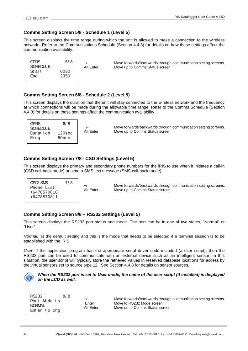
iRIS Datalogger User Guide V1.50
46 iQuest (NZ) Ltd - PO Box 15169, Hamilton, New Zealand Tel: +64 7 857-0810 Fax: +64 7 857-0811 Email: [email protected]
Comms Setting Screen 5/8 - Schedule 1 (Level 5) This screen displays the time range during which the unit is allowed to make a connection to the wireless network. Refer to the Communications Schedule (Section 4.4.3) for details on how these settings affect the communication availability.
Comms Setting Screen 6/8 - Schedule 2 (Level 5) This screen displays the duration that the unit will stay connected to the wireless network and the frequency at which connections will be made during the allowable time range. Refer to the Comms Schedule (Section 4.4.3) for details on these settings affect the communication availability.
Comms Setting Screen 7/8– CSD Settings (Level 5) This screen displays the primary and secondary phone numbers for the iRIS to use when it initiates a call-in (CSD call-back mode) or send a SMS text message (SMS call-back mode).
Comms Setting Screen 8/8 – RS232 Settings (Level 5) This screen displays the RS232 port status and mode. The port can be in one of two states, “Normal” or “User”. Normal: is the default setting and this is the mode that needs to be selected if a terminal session is to be established with the iRIS. User: If the application program has the appropriate serial driver code included (a user script), then the RS232 port can be used to communicate with an external device such as an intelligent sensor. In this situation, the user script will typically store the retrieved values in reserved database locations for access by the virtual sensors set to source type 12. See Section 4.4.8 for details on sensor sources.
When the RS232 port is set to User mode, the name of the user script (if installed) is displayed on the LCD as well.
GPRS 5/8 SCHEDULE Start 0030 End 2359
GPRS 6/8 SCHEDULE Duration 120sec Freq 60min
+/- Move forwards/backwards through communication setting screens. Alt Enter Move up to Comms Status screen
+/- Move forwards/backwards through communication setting screens. Alt Enter Move up to Comms Status screen
CSD/SMS 7/8 Phone List: +6478570810 +6478570811
+/- Move forwards/backwards through communication setting screens. Alt Enter Move up to Comms Status screen
RS232 8/8 Port Mode is NORMAL Enter to chg
+/- Move forwards/backwards through communication setting screens. Enter Move to RS232 Mode screen Alt Enter Move up to Comms Status screen
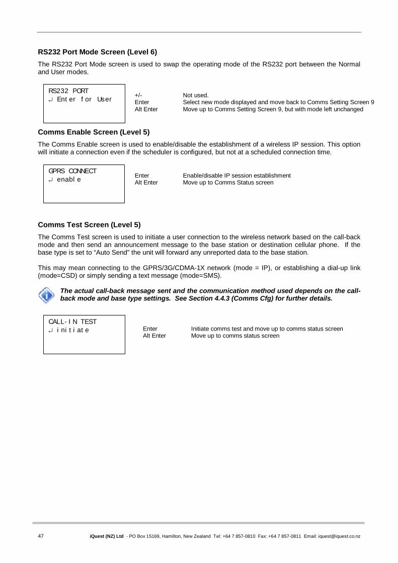
47 iQuest (NZ) Ltd - PO Box 15169, Hamilton, New Zealand Tel: +64 7 857-0810 Fax: +64 7 857-0811 Email: [email protected]
RS232 Port Mode Screen (Level 6) The RS232 Port Mode screen is used to swap the operating mode of the RS232 port between the Normal and User modes.
Comms Enable Screen (Level 5) The Comms Enable screen is used to enable/disable the establishment of a wireless IP session. This option will initiate a connection even if the scheduler is configured, but not at a scheduled connection time.
Comms Test Screen (Level 5) The Comms Test screen is used to initiate a user connection to the wireless network based on the call-back mode and then send an announcement message to the base station or destination cellular phone. If the base type is set to “Auto Send” the unit will forward any unreported data to the base station. This may mean connecting to the GPRS/3G/CDMA-1X network (mode = IP), or establishing a dial-up link (mode=CSD) or simply sending a text message (mode=SMS).
The actual call-back message sent and the communication method used depends on the call-back mode and base type settings. See Section 4.4.3 (Comms Cfg) for further details.
CALL-IN TEST initiate
Enter Initiate comms test and move up to comms status screen Alt Enter Move up to comms status screen
GPRS CONNECT enable
Enter Enable/disable IP session establishment Alt Enter Move up to Comms Status screen
RS232 PORT Enter for User
+/- Not used. Enter Select new mode displayed and move back to Comms Setting Screen 9 Alt Enter Move up to Comms Setting Screen 9, but with mode left unchanged
iRIS Datalogger User Guide V1.50
48 iQuest (NZ) Ltd - PO Box 15169, Hamilton, New Zealand Tel: +64 7 857-0810 Fax: +64 7 857-0811 Email: [email protected]
5.3 SMS Communication The iRIS can send a standard text message in response to a request received via SMS (see Section 5.3.1 below). If the call-back mode is set to 2 (SMS) a message is also sent if an alarm is activated, a comms scheduler trigger occurs or user initiated communications test is done. The SMS message is constructed from the logger’s date and time, site name plus the sensor number, name and current value of all the enabled sensors and finally the last measured RSSI value. The format is best shown in this example: 12/06/2009 12:34:56 My Site Name,1:Water Lvl= 27.69,2:Batt Volts=12.73,3:Supp Volts= 23.90,RSSI=19
If the message was sent because of an alarm event, the message will have the prefix “ALM!” at the start of the message.
5.3.1 SMS Text Commands The iRIS can also accept incoming SMS messages and if they are valid it will respond appropriately. To use this function, simply send a text message to the iRIS voice number with a message as described below. The message is not case-sensitive. The two commands currently supported are: Request Current Sensor Values. Send the message “RQ”. The iRIS will reply with the standard SMS message described above. If the requester message does not begin with RQ, the response will be the message “Invalid command!” Go On-Line. Send “GOL”. This is useful as a poll-on-demand type function. The iRIS will not reply to this command, but will immediately initiate a wireless connection of the type defined in the Callback Mode setting. Typically this is an IP connection, but could be a CSD dial-up connection or even an SMS message (but to the numbers defined in the Phone Number configuration, not the requester’s number).
The SMS function is only available if the SMS service has been enabled in the SIM card (GPRS and 3G models) or in the CDMA service (CDMA models) and there is not a wireless IP or CSD dial-up session active. If the call-back mode is set to IP or CSD, then the iRIS will respond to incoming SMS requests, but will not send an SMS message if an alarm occurs or the communication test function is initiated from the LCD/keypad. In this situation, the iRIS will attempt to either establish a wireless IP link or dial a modem at the primary number programmed into the CSD phone list.
5.4 General Hints If the iRIS will be installed in an outdoor situation, try to ensure that the LCD is facing away from direct
sunlight. This will help to enhance the readability of the display. If the unit is not to be used for some time, disconnect the internal battery to prevent it discharging. Always check the time and date are correct when commissioning the unit. Take into account daylight
saving, which is almost universally not used in datalogging applications to maintain data currency. Datalogger clocks are generally set to standard time in the local time zone.
Immediately following installation, use the initialisation function (available on the Miscellaneous terminal
menu) to clear data and totals that may have been logged before the commissioning. See Section 4.4.14.
The three iRIS application program segments (.irs files) can normally be upgraded with no effect upon
the logged data or iRIS configuration. In the case of a major upgrade that may affect the internal memory of the unit, iQuest will issue an upgrade notification explaining the procedure that should be followed when upgrading your unit. See Section 16 for details on how to upgrade the firmware and software in an iRIS.

49 iQuest (NZ) Ltd - PO Box 15169, Hamilton, New Zealand Tel: +64 7 857-0810 Fax: +64 7 857-0811 Email: [email protected]
6 Sensor Connection Examples
6.1 Introduction to Connection Examples The following generic examples are included to give a basic overview of how to connect standard / common instrument types to the iRIS and configure it to suit them. For more detailed or specialised examples, please refer to the Application Notes section on the iQuest website.
The I/O terminals and wiring information in these examples are for an iRIS 350. The corresponding terminals on the iRIS 220/320 for those that differ are shown here.
Function iRIS 350 iRIS 220 / 320
Digital Input 1 DIO1 DI1 Digital Input 2 DIO2 DI2 Digital Output 1 DIO3 DO1 Digital Output 1 DIO4 DO2 Excitation (Vout) AOUT 5V OP
Table 7 - I/O Terminal Differences

iRIS Datalogger User Guide V1.50
50 iQuest (NZ) Ltd - PO Box 15169, Hamilton, New Zealand Tel: +64 7 857-0810 Fax: +64 7 857-0811 Email: [email protected]
6.2 Connecting a Flow Meter or Rain Gauge A common use for the iRIS is logging data from pulse sources such as flow meters or rain gauges. Connecting such devices to the iRIS is very simple – wire the switch between the appropriate digital input (DIO1 or DIO2) and the digital ground (DGND) terminal. Both of the digital inputs provide a “wetting current” for clean contact sources, but transistor switches and active signals (ones that supply a voltage) can also be used. If a transistor switch is used, connect the collector (+) to the digital input and the emitter (-) to the DGND. See Section 3.5.5 for details on the digital inputs and setting up the input debounce mode. Both inputs can be used simultaneously and each input has three associated totalisers, which are viewable from the LCD. See section 5.2.7. These totalisers operate even if the input is not configured as a source to one of the six virtual sensors. The diagram below shows the typical connection diagram for such an installation. It assumes the use of DIO1 as the pulse input channel. The charging source can be any d.c supply from 15V – 30V, including a directly connected solar panel. TOP iRIS I/O Connector The sensor should be configured for the correct channel, scaling and logging regime as described in section 4.4.8. Event mode (sensor mode=2) can be used to reduce the quantity of data logged, especially for rainfall where the actual data density is low. Three typical sensor configuration examples for this type of instrument are shown below. The instrument is a 0.5mm tipping bucket rain gauge and is logged every 15 minutes for examples 1 and 2.
* Sensor 1 Cfg (Now: 0.0) 0 Exit 1 Source [5: Pulse1] 2 Name [Rainfall] 3 Mode [Instant] 4 Multiplier [ 0.500] 5 Offset [ 0.0000] 6 Log Multiplier [10] 7 Log Rate [15min] 8 Alarms 9 Data
* Sensor 1 Cfg (Now: 0.0) 0 Exit 1 Source [5: Pulse1] 2 Name [Rainfall] 3 Mode [Event] 4 Multiplier [ 0.500] 5 Offset [ 0.0000] 6 Log Multiplier [10] 7 Log Rate [15min] 8 Alarms 9 Data
* Sensor 1 Cfg (Now: 0.0) 0 Exit 1 Source [5: Pulse1] 2 Name [Rainfall] 3 Mode [Event] 4 Multiplier [ 0.500] 5 Offset [ 0.0000] 6 Log Multiplier [10] 7 Log Rate [0min] 8 Alarms 9 Data
Example 1: Normal Timed This logs the total every 15 minutes, even if it is zero. This produces the most data as every “time slot” has an associated sample.
Example 2: Timed Event This logs the total every 15 minutes only if it is non-zero. It also inserts a zero record one log interval earlier, if there has not been a value logged.
Example 3: True Event This logs every event to a one second resolution. If there is more than one count in a second, the total is logged. No zero samples are logged.
AI4 AI3 AI2 AI1 AGND AOUT DIO4 DIO3 DIO2 DIO1 SDI-12 DGND 12V+ GND (-) VIN+ GND (-)
Flow Meter or Rain Gauge
Charging source e.g. solar panel

51 iQuest (NZ) Ltd - PO Box 15169, Hamilton, New Zealand Tel: +64 7 857-0810 Fax: +64 7 857-0811 Email: [email protected]
6.3 Connecting a 0-5V Pressure Transducer Connecting a standard sensor (such as a pressure transducer that provides a 0-5V signal) to an iRIS is relatively straightforward. The sensor can be powered from the iRIS’s 12V supply and optionally controlled by a digital output to save power. However, the iRIS’s internal battery is NOT recommended for directly powering the sensor alone if the charging source is a solar panel, as it is a relatively low capacity type. Connect a supplementary external 12V battery (7A/Hr or larger) to increase the available storage. The diagram below shows the typical connection diagram for such an installation. It assumes the use of AI1 as the desired input channel. It also shows the connection of the switched supply from DIO4. TOP iRIS I/O Connector The sensor should be configured for the correct channel, scaling and logging regime as described in Section 4.4.8. Also, see Section 8 for a description of how to accurately scale the sensor. A typical sensor configuration example for this type of installation is shown here. The instrument is a 10 metre, 0-5V output pressure transducer. The level is averaged and the result logged every 15 minutes.
The iRIS supports activation of one or both digital outputs with a schedule. See Section 4.4.11 for more details and an example. Therefore, if further power reduction is to be achieved by controlling the transducer power, follow this procedure:
1. Connect the transducer supply to the switched 12V output (DIO4 on the iRIS 350 or DO2 on
the iRIS 220/320) 2. Configure the digital output’s mode to be Schedule (Mode = 1). 3. Set up the digital output’s schedule to match the sensor’s logging period, but with the digital
output being set to activate the desired amount of time before the sensor is to log and with sufficient “on” time to ensure an overlap with the logging time.
4. Ensure the sensor mode is set to Instant (0) or 1 minute average (4).
AI4 AI3 AI2 AI1 AGND AOUT DIO4 DIO3 DIO2 DIO1 SDI-12 DGND 12V+ GND (-) VIN+ GND (-)
+ Signal Pressure Transducer -
Charging source e.g. solar panel
12V Battery (Required)
+ -
* Sensor 1 Cfg (Now: 6.2454 [3.1226V] 0 Exit 1 Source [1: Analog1] 2 Name [Water Lvl] 3 Mode [Period Avg] 4 Multiplier [ 2.0000] 5 Offset [ 0.0000] 6 Log Multiplier [1000] 7 Log Rate [15min] 8 Alarms 9 Data

iRIS Datalogger User Guide V1.50
52 iQuest (NZ) Ltd - PO Box 15169, Hamilton, New Zealand Tel: +64 7 857-0810 Fax: +64 7 857-0811 Email: [email protected]
6.4 Connecting a 2-Wire Loop-Powered 4-20mA Sensor The iRIS also supports the connection of many types of industry standard 4-20mA current loop instruments such as ultrasonic or radar level sensors. A very common configuration used with these devices is known as two-wire or loop-powered mode. This requires only two wires to the sensor and the 4-20mA loop current provides power for the sensor as well as being the proportional analog sensor signal. However, theses sensors often require a minimum voltage across them that may not be reliably achieved with a 12V supply, taking into account the voltage drop across the sense resistor. In such cases, a separate 12-24V boosted sensor supply is recommended. The diagram below shows the recommended connection diagram for such an installation. It assumes the use of AI1 as the desired input channel. The current sink resistor should be enabled for the appropriate analog input. On the iRIS 350 this is provided on-board. The iRIS 220/320 an external resistor needs to be fitted. See Section 3.5.4 for details on the analog input links. On the iRIS 350 the internal 100 sense resistor generates a 0.4-2V signal (from the 4-20mA current), which is then measured at the analog input. The sensor should be configured for the correct channel, scaling and logging regime as described in section 4.4.8. An offset value will be required as part of the configuration, as the 4mA (0.4V) offset needs to be eliminated. TOP iRIS I/O Connector
BOTTOM A typical sensor configuration example for this type of installation is shown here. The instrument is a 10 metre, 4-20mA output ultrasonic transducer. The level is averaged and the result logged every 15 minutes.
If power consumption is an issue, the sensor can be controlled by a digital output on a timed basis. See the description in Section 6.3 above.
* Sensor 1 Cfg (Now: 6.1200 [1.3792V] 0 Exit 1 Source [1: Analog1] 2 Name [Water Lvl] 3 Mode [Period Avg] 4 Multiplier [ 6.2500] 5 Offset [ -2.5000] 6 Log Multiplier [1000] 7 Log Rate [15min] 8 Alarms 9 Data
Isolated 12V – 24V DC- DC Converter
- + 24V 12V - +
Charging source E.g. solar panel
- + External
12V Battery (Required)
- Signal 4-20mA Sensor +
AI4 AI3 AI2 AI1 AGND AOUT DIO4 DIO3 DIO2 DIO1 SDI-12 DGND 12V+ GND (-) VIN+ GND (-)

53 iQuest (NZ) Ltd - PO Box 15169, Hamilton, New Zealand Tel: +64 7 857-0810 Fax: +64 7 857-0811 Email: [email protected]
6.5 Connecting an Up/Down Water Level Instrument A relatively common type of digital water level instrument is one that provides two pulse outputs. One output generates a pulse for each increment and the other for each decrement in level. The iRIS maintains a record of these steps and therefore the relative level.
This instrument type is NOT the same as a quadrature encoder which uses the relative phase of the two signals to determine direction. See Section 6.9 for details on the quadrature sensors.
These instruments normally require a 12V supply and this is readily obtained from the iRIS. A supplementary 12V battery can be connected if desired. Typically, this type of instrument requires very little current, so the internal iRIS battery will normally suffice. The diagram below shows the required connects for such an installation. The incrementing output must be connected to DI1 and the decrementing output to DI2. TOP iRIS I/O Connector *
BOTTOM A typical sensor configuration example for this type of installation is shown below. The instrument is a standard digital up/down water level encoder. The level is averaged and the result logged every 15 minutes.
* Sensor 1 Cfg (Now: 0.0) 0 Exit 1 Source [11: Up/Dn] 2 Name [Water Lvl] 3 Mode [Period Avg] 4 Multiplier [ 0.001] 5 Offset [ 0.000] 6 Log Multiplier [1000] 7 Log Rate [15min] 8 Alarms 9 Data
AI4 AI3 AI2 AI1 AGND AOUT DIO4 DIO3 DIO2 DIO1 SDI-12 DGND 12V+ GND (-) VIN+ GND (-) - +
External 12V Battery (Optional)
DN Up/Down UP Water Level +12V Sensor 0V
Charging source e.g. solar panel
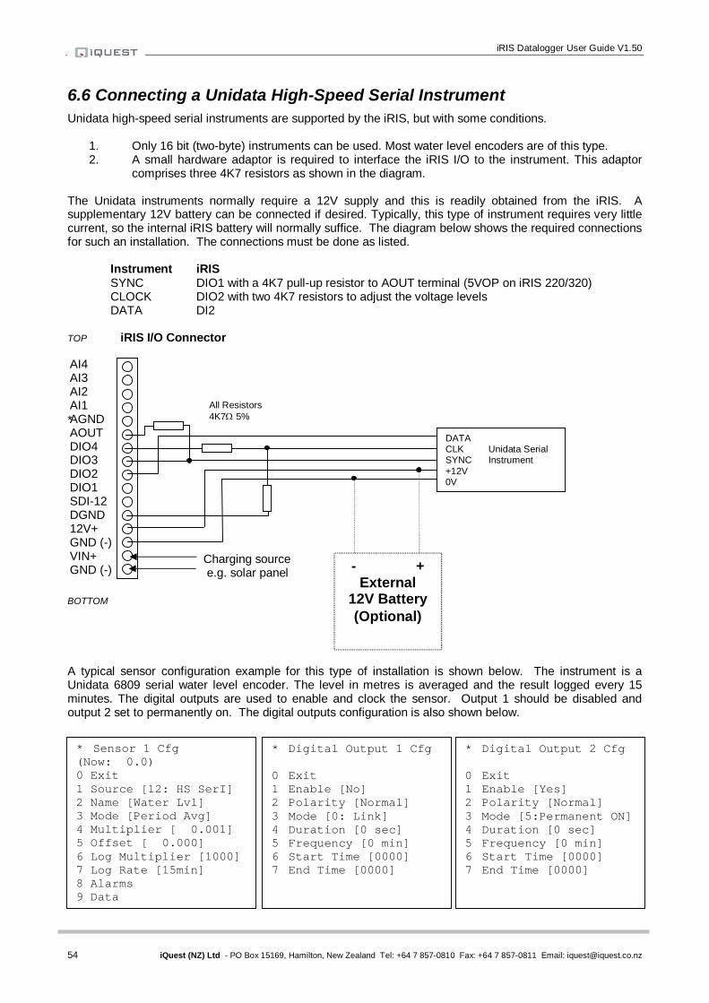
iRIS Datalogger User Guide V1.50
54 iQuest (NZ) Ltd - PO Box 15169, Hamilton, New Zealand Tel: +64 7 857-0810 Fax: +64 7 857-0811 Email: [email protected]
6.6 Connecting a Unidata High-Speed Serial Instrument Unidata high-speed serial instruments are supported by the iRIS, but with some conditions.
1. Only 16 bit (two-byte) instruments can be used. Most water level encoders are of this type. 2. A small hardware adaptor is required to interface the iRIS I/O to the instrument. This adaptor
comprises three 4K7 resistors as shown in the diagram. The Unidata instruments normally require a 12V supply and this is readily obtained from the iRIS. A supplementary 12V battery can be connected if desired. Typically, this type of instrument requires very little current, so the internal iRIS battery will normally suffice. The diagram below shows the required connections for such an installation. The connections must be done as listed. Instrument iRIS
SYNC DIO1 with a 4K7 pull-up resistor to AOUT terminal (5VOP on iRIS 220/320) CLOCK DIO2 with two 4K7 resistors to adjust the voltage levels DATA DI2
TOP iRIS I/O Connector *
BOTTOM A typical sensor configuration example for this type of installation is shown below. The instrument is a Unidata 6809 serial water level encoder. The level in metres is averaged and the result logged every 15 minutes. The digital outputs are used to enable and clock the sensor. Output 1 should be disabled and output 2 set to permanently on. The digital outputs configuration is also shown below.
* Sensor 1 Cfg (Now: 0.0) 0 Exit 1 Source [12: HS SerI] 2 Name [Water Lvl] 3 Mode [Period Avg] 4 Multiplier [ 0.001] 5 Offset [ 0.000] 6 Log Multiplier [1000] 7 Log Rate [15min] 8 Alarms 9 Data
* Digital Output 1 Cfg 0 Exit 1 Enable [No] 2 Polarity [Normal] 3 Mode [0: Link] 4 Duration [0 sec] 5 Frequency [0 min] 6 Start Time [0000] 7 End Time [0000]
* Digital Output 2 Cfg 0 Exit 1 Enable [Yes] 2 Polarity [Normal] 3 Mode [5:Permanent ON] 4 Duration [0 sec] 5 Frequency [0 min] 6 Start Time [0000] 7 End Time [0000]
AI4 AI3 AI2 AI1 AGND AOUT DIO4 DIO3 DIO2 DIO1 SDI-12 DGND 12V+ GND (-) VIN+ GND (-) - +
External 12V Battery (Optional)
DATA CLK Unidata Serial SYNC Instrument +12V 0V
Charging source e.g. solar panel
All Resistors 4K7 5%

55 iQuest (NZ) Ltd - PO Box 15169, Hamilton, New Zealand Tel: +64 7 857-0810 Fax: +64 7 857-0811 Email: [email protected]
6.7 Connecting Analog Wind Instruments Many wind measurement instruments operate in an analog mode. The wind direction sensor is usually a potentiometer which is driven by the buffered 5.0V output from the iRIS. The wiper signal is connected to one of the analog inputs. As the iRIS analog inputs have low pass filtering included, there is no need for external components to remove noise. The anemometers usually provide a switched pulse signal from a transistor or opt-coupler. This drives a digital input, operating in counter mode and the frequency is measured, scaled and logged.
For the anemometer to operate correctly, the pulse amplitude must be at least 3V p-p. Some instruments emit a low level a.c signal in the order of millivolts. In these cases a simple transistor switch to create a suitable pulse must be included. Please contact iQuest for details.
The diagram below shows a typical installation. TOP iRIS I/O Connector BOTTOM A typical sensor configuration example for this type of installation is shown below. The instruments are a Vector A101M wind speed sensor providing pulses that are converted to metres/sec and a Vector W200P wind direction sensor. The speed and direction are averaged and the results logged every 10 minutes and the wind speed min and max (lull and gust) are also logged.
AI4 AI3 AI2 AI1 AGND AOUT DI2 DI1 DO2 DO1 SDI-12 DGND 12V+ GND (-) VIN+ GND (-)
- + External
12V Battery (Optional)
Wind PULSE Speed +12V Sensor 0V
Charging source e.g. solar panel
SUPPLY SIGNAL GND
Wind Direction Sensor
* Sensor 1 Cfg (Now: 3.11) 0 Exit 1 Source [9: Freq 1] 2 Name [Wind Spd] 3 Mode [Period Avg+Min+Max] 4 Multiplier [ 0.010] 5 Offset [ 0.000] 6 Log Multiplier [ 10] 7 Log Rate [10min] 8 Alarms 9 Data
* Sensor 2 Cfg (Now: 176.00) 0 Exit 1 Source [1: Analog1] 2 Name [Wind Dir] 3 Mode [Scalar Avg] 4 Multiplier [ 71.800] 5 Offset [ 0.000] 6 Log Multiplier [ 1] 7 Log Rate [10min] 8 Alarms 9 Data
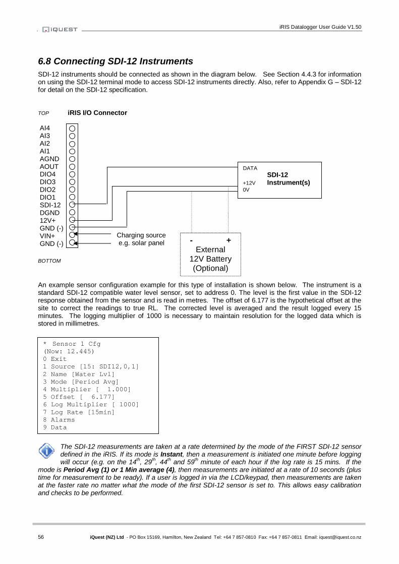
iRIS Datalogger User Guide V1.50
56 iQuest (NZ) Ltd - PO Box 15169, Hamilton, New Zealand Tel: +64 7 857-0810 Fax: +64 7 857-0811 Email: [email protected]
6.8 Connecting SDI-12 Instruments SDI-12 instruments should be connected as shown in the diagram below. See Section 4.4.3 for information on using the SDI-12 terminal mode to access SDI-12 instruments directly. Also, refer to Appendix G – SDI-12 for detail on the SDI-12 specification. TOP iRIS I/O Connector
BOTTOM An example sensor configuration example for this type of installation is shown below. The instrument is a standard SDI-12 compatible water level sensor, set to address 0. The level is the first value in the SDI-12 response obtained from the sensor and is read in metres. The offset of 6.177 is the hypothetical offset at the site to correct the readings to true RL. The corrected level is averaged and the result logged every 15 minutes. The logging multiplier of 1000 is necessary to maintain resolution for the logged data which is stored in millimetres.
The SDI-12 measurements are taken at a rate determined by the mode of the FIRST SDI-12 sensor defined in the iRIS. If its mode is Instant, then a measurement is initiated one minute before logging will occur (e.g. on the 14th, 29th, 44th and 59th minute of each hour if the log rate is 15 mins. If the
mode is Period Avg (1) or 1 Min average (4), then measurements are initiated at a rate of 10 seconds (plus time for measurement to be ready). If a user is logged in via the LCD/keypad, then measurements are taken at the faster rate no matter what the mode of the first SDI-12 sensor is set to. This allows easy calibration and checks to be performed.
* Sensor 1 Cfg (Now: 12.445) 0 Exit 1 Source [15: SDI12,0,1] 2 Name [Water Lvl] 3 Mode [Period Avg] 4 Multiplier [ 1.000] 5 Offset [ 6.177] 6 Log Multiplier [ 1000] 7 Log Rate [15min] 8 Alarms 9 Data
AI4 AI3 AI2 AI1 AGND AOUT DIO4 DIO3 DIO2 DIO1 SDI-12 DGND 12V+ GND (-) VIN+ GND (-) - +
External 12V Battery (Optional)
DATA SDI-12 +12V Instrument(s) 0V
Charging source e.g. solar panel

57 iQuest (NZ) Ltd - PO Box 15169, Hamilton, New Zealand Tel: +64 7 857-0810 Fax: +64 7 857-0811 Email: [email protected]
6.9 Connecting Quadrature Encoders A commonly used type of digital water level instrument is one that provides two pulse outputs, the direction of movement being determined by the phase difference between the two signals. The iRIS tracks these steps and therefore the relative water level. These instruments are passive and do not require a power supply. This implementation makes use of the two digital inputs, DIO1 and DIO2 (DI1 and DI2 on the iRIS 220/320) as the reference channel and auxiliary channels respectively. The installation differs between the older iRIS 220/320 and the current iRIS 350. The following two sections describe how to incorporate a quadrature sensor on these models. 6.9.1 iRIS 350 Installation On the iRIS 350, this software version which emulates an iRIS 320 does not leave any digital inputs available for use with another sensor such as a rain gauge or flow meter. However, future versions will make DIO3 and/or DIO4 available for such a purpose as the hardware will support this. The diagram below shows the connections for an installation with an iRIS 350. The debounce links for DIO1 and DIO2 (DI1, DI2) should be fitted.
If the direction is incorrect, reverse the two channels.
TOP iRIS 350 I/O Connector
BOTTOM
- + External
12V Battery (Optional)
B Quadrature A Shaft Encoder COM
Charging source e.g. solar panel
AI4 AI3 AI2 AI1 AGND AOUT DIO4 DIO3 DIO2 DIO1 SDI-12 DGND 12V+ GND (-) VIN+ GND (-)

iRIS Datalogger User Guide V1.50
58 iQuest (NZ) Ltd - PO Box 15169, Hamilton, New Zealand Tel: +64 7 857-0810 Fax: +64 7 857-0811 Email: [email protected]
6.9.2 iRIS 220 / iRIS 320 Installation NOTE: Using this type of encoder on the older iRIS 220 / iRIS 320 requires iRIS hardware (PCB Rev 1.2, four analog inputs), firmware version VN/2.23 or later and software V1.23 or later. A commonly used type of digital water level instrument is one that provides two pulse outputs, the direction of movement being determined by the phase difference between the two signals. The iRIS tracks these steps and therefore the relative water level. These instruments are passive and do not require a power supply. This implementation makes use of a digital input (DI2) as the reference channel and an analog input (AIN4), which is used as a simulated digital input, as the auxiliary channel. This scenario leaves DI1 free for use with another sensor such as a rain gauge or flow meter. The diagram below shows the connections for such an installation. Normally, the A output is connected to DI2 and the B output to AIN4. A 2K2 resistor must be connected between the 5VOP terminal and the AIN4 terminal to provide the supply for the simulated digital input. In addition a 100nF capacitor must be fitted between the DI2 terminal and the DGND terminal to reinstate the debounce function that is disabled by removing the link as mentioned below. The resistor and capacitor do not need to be precision types.
If the direction is incorrect, reverse the two channels.
The debounce link for DI2 must be removed for correct operation, especially with instruments such as the HS AD150 that have an in-built 1K current limit resistor. The debounce link also enables a dc source that will cause problems with the simulated digital input on AIN4 if it is left connected.
TOP iRIS 220 / 320 I/O Connector
BOTTOM
Remove this jumper
- + External
12V Battery (Optional)
B Quadrature A Shaft Encoder COM
Charging source e.g. solar panel
AI4 AI3 AI2 AI1 AGND 5VOP DI2 DI1 DO2 DO1 SDI-12 DGND 12V+ GND (-) VIN+ GND (-)
4K7 ¼ w 5% resistor
100nF 50V capacitor

59 iQuest (NZ) Ltd - PO Box 15169, Hamilton, New Zealand Tel: +64 7 857-0810 Fax: +64 7 857-0811 Email: [email protected]
6.10 Connecting a Vaisala WXT5x0 Weather Transmitter The Vaisala WXT5x0 Weather Transmitter is a compact, well-featured instrument that is ideal for implementing small weather stations. The iRIS supports the connection of these units using the SDI-12 interface.
Although the standard iRIS software only supports six sensors, it allows a special exception when using the WXT5x0, which provides seven parameters. To achieve this, hail measurements are logged as a “secondary” sensor linked to rainfall, (which must be configured as sensor 6). Hail is logged with an array ID of 10 and it shares the same logging configuration as rainfall (logging rate, event mode etc). The hail “sensor” is not visible from the LCD or terminal sessions.
The instrument should be connected as shown below. The SDI-12 interface adaptor is omitted for clarity. This diagram assumes the use of the optional interface cable that is provided by Vaisala. Cover the screen wire (clear) and unused wire ends (pink, yellow and grey) heater with sleeving or heatshrink tubing to avoid short circuits. TOP iRIS I/O Connector
BOTTOM 6.10.1 Configuration Use the Vaisala WXT Configuration Tool to set up the WXT5x0 to provide the correct composite message and processing settings. Then configure the iRIS sensor settings to suit the instrument. The screen shots on the next page (Section 6.10.2) show the settings that are recommended for this application. The last subsection, (Section 6.10.3) shows the settings for each of the sensors to enable the WXT5x0 data to be acquired and logged.
AI4 AI3 AI2 AI1 AGND AOUT DIO4 DIO3 DIO2 DIO1 SDI-12 DGND 12V+ GND (-) VIN+ GND (-)
Data Out (TxD) Data In (RxD) WXT5x0 Vin+ Weather Data Gnd Instrument Vin Gnd
Green
Brown
Blue
White
Screen (Clear)
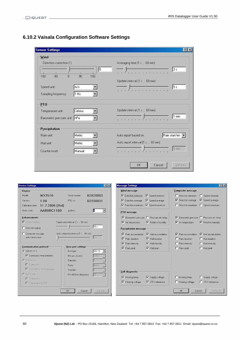
iRIS Datalogger User Guide V1.50
60 iQuest (NZ) Ltd - PO Box 15169, Hamilton, New Zealand Tel: +64 7 857-0810 Fax: +64 7 857-0811 Email: [email protected]
6.10.2 Vaisala Configuration Software Settings
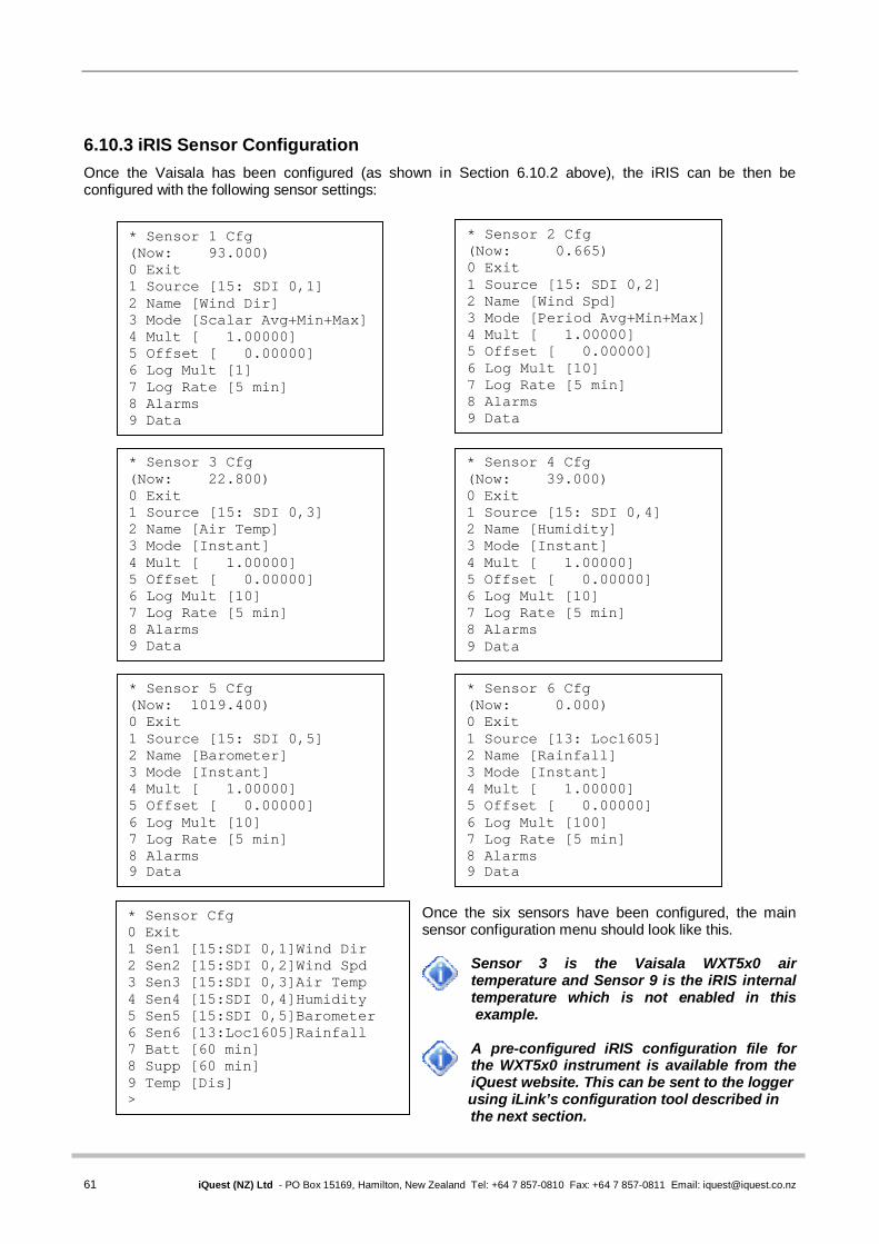
61 iQuest (NZ) Ltd - PO Box 15169, Hamilton, New Zealand Tel: +64 7 857-0810 Fax: +64 7 857-0811 Email: [email protected]
6.10.3 iRIS Sensor Configuration Once the Vaisala has been configured (as shown in Section 6.10.2 above), the iRIS can be then be configured with the following sensor settings:
Once the six sensors have been configured, the main sensor configuration menu should look like this.
Sensor 3 is the Vaisala WXT5x0 air temperature and Sensor 9 is the iRIS internal temperature which is not enabled in this
example.
A pre-configured iRIS configuration file for the WXT5x0 instrument is available from the iQuest website. This can be sent to the logger
using iLink’s configuration tool described in the next section.
* Sensor Cfg 0 Exit 1 Sen1 [15:SDI 0,1]Wind Dir 2 Sen2 [15:SDI 0,2]Wind Spd 3 Sen3 [15:SDI 0,3]Air Temp 4 Sen4 [15:SDI 0,4]Humidity 5 Sen5 [15:SDI 0,5]Barometer 6 Sen6 [13:Loc1605]Rainfall 7 Batt [60 min] 8 Supp [60 min] 9 Temp [Dis] >
* Sensor 1 Cfg (Now: 93.000) 0 Exit 1 Source [15: SDI 0,1] 2 Name [Wind Dir] 3 Mode [Scalar Avg+Min+Max] 4 Mult [ 1.00000] 5 Offset [ 0.00000] 6 Log Mult [1] 7 Log Rate [5 min] 8 Alarms 9 Data
* Sensor 2 Cfg (Now: 0.665) 0 Exit 1 Source [15: SDI 0,2] 2 Name [Wind Spd] 3 Mode [Period Avg+Min+Max] 4 Mult [ 1.00000] 5 Offset [ 0.00000] 6 Log Mult [10] 7 Log Rate [5 min] 8 Alarms 9 Data
* Sensor 5 Cfg (Now: 1019.400) 0 Exit 1 Source [15: SDI 0,5] 2 Name [Barometer] 3 Mode [Instant] 4 Mult [ 1.00000] 5 Offset [ 0.00000] 6 Log Mult [10] 7 Log Rate [5 min] 8 Alarms 9 Data
* Sensor 3 Cfg (Now: 22.800) 0 Exit 1 Source [15: SDI 0,3] 2 Name [Air Temp] 3 Mode [Instant] 4 Mult [ 1.00000] 5 Offset [ 0.00000] 6 Log Mult [10] 7 Log Rate [5 min] 8 Alarms 9 Data
* Sensor 4 Cfg (Now: 39.000) 0 Exit 1 Source [15: SDI 0,4] 2 Name [Humidity] 3 Mode [Instant] 4 Mult [ 1.00000] 5 Offset [ 0.00000] 6 Log Mult [10] 7 Log Rate [5 min] 8 Alarms 9 Data
* Sensor 6 Cfg (Now: 0.000) 0 Exit 1 Source [13: Loc1605] 2 Name [Rainfall] 3 Mode [Instant] 4 Mult [ 1.00000] 5 Offset [ 0.00000] 6 Log Mult [100] 7 Log Rate [5 min] 8 Alarms 9 Data

iRIS Datalogger User Guide V1.50
62 iQuest (NZ) Ltd - PO Box 15169, Hamilton, New Zealand Tel: +64 7 857-0810 Fax: +64 7 857-0811 Email: [email protected]
7 Using iLink’s Sensor Configuration Tool
To optimise the process of maintaining multiple iRIS installations with the same (or similar) sensor configuration, iLink includes a graphical configuration tool. This allows the configuration of any the sensors to be changed, sent to the logger or saved to disk. It also supports the retrieval of sensor settings from the logger and from disk. This means that setting up new loggers is made very simple as a common configuration file can be sent to each logger. 7.1 iRIS Sensor Configuration Example This example shows how to set up a simple iRIS sensor configuration to measure water level from an SDI-12 sensor and also log internal battery voltage. This example is valid for all models
1. Connect to the iRIS using iLink.
2. Invoke the iRIS configuration form by clicking the Logger Cfg tool button or by selecting the menu item Configuration->iRIS Logger Configuration. This will bring up the iRIS Sensor Configuration form as shown here.
3. Next, set up the water level sensor. Enter the sensor name “Water Lvl” (max 10 characters).
4. Now set the sensor source from the drop down list. Select source 15, SDI-12. Then enter the correct SDI-12 instrument address and variable. In our example the instrument has an address of zero (0) and we require the first value (variable 1).

63 iQuest (NZ) Ltd - PO Box 15169, Hamilton, New Zealand Tel: +64 7 857-0810 Fax: +64 7 857-0811 Email: [email protected]
5. Enter the multiplier to scale the value. For SDI-12 instruments, the multiplier is typically 1 as the instrument itself provides an actual value in engineering units. Enter an offset if required and known at this point. More often, this is set on site to calibrate the measurement to a known reference of datum. In this case the offset can be set by using the LCD calibration screen. See Section 5.2.6.
6. The General configuration should now look like this.
7. Now select the “Logging” tab and set up the logging parameters. In this example we are measuring averaged water level in metres so we need to set the logging multipler to 1000 to store the value as an integer (mm). The logging rate is 15 minutes. Our hypothetical sensor generates an error value of 999.99 if it develops a fault or is unable to take a measurement. Rather than have this cause a spike in our data, we are choosing to reject values above our expected maximum of 20 metres. We also want to capture the minimum or maximum values over the period, so we enable the logging of these as well.
8. The Logging configuration should look like this.
9. Next select the “Alarms” tab. We are going to set a low level alarm at 3.5 metres and a high level alarms at 17 metres. Both alarms will have a reset differential of 0.1 metres making the reset levels 3.6 metres and 16.9 metres respectively. The alarms are set to be immediately acting, so no duration delay is required.
10. The Logging configuration should look like this.
Note that the entry for Sensor 1 on the sensor list will now have a red question mark (?) next to it. This indicates that the configuration has been changed and has not yet been sent to the iRIS and/or saved to disk.

iRIS Datalogger User Guide V1.50
64 iQuest (NZ) Ltd - PO Box 15169, Hamilton, New Zealand Tel: +64 7 857-0810 Fax: +64 7 857-0811 Email: [email protected]
11. Next set up the internal battery sensor by clicking on the sensor in the Internal Sensors list. This will
enable the appropriate configuration panel for that sensor. Set up the logging rate and if required an alarm. In our example we log the battery voltage every 60 minutes and have set a low voltage alarm at 12.1 volts which resets when the battery rises to 12.5 volts again.
12. The Logging configuration tab should look like this.
13. The sensor configuration is complete. Now enter the logger’s site name in the Site Name field in the Misc panel at the bottom of the form. The site name is the text that appears on the title screen on the LCD and also in the header of downloaded data files.
14. Save the configuration to disk by clicking the [Save] button. Enter a suitable name for your
configuration. Our example here will use the file name “SDI-12 Level and Battery.cfg”. The file can then be opened and sent to other loggers requiring the same sensor configuration at a later date.
15. Finally, send the configuration to the connected iRIS. To do this, click the [Send] button. You will be
prompted about what you want to send. Typically, always select “All” unless only enabled sensors need to be sent over a slow link such as radio in which case you would chose “Yes” Clicking “No” will cancel the operation and send nothing.
16. The sensor configuration will be sent in a series of blocks with a progress dialog indicating the status. The Site Name is also sent at the end. The operation can be cancelled if required by clicking the [Abort] button.
17. The process is now complete. If you want to edit or save the configuration in an already configured iRIS, the reverse operation can be done by using the [Retrieve] button. The configuration can then be edited and sent back to the iRIS and/or saved to disk.
This tool only supports the configuration of sensor parameters. The communications and other settings should be done by the normal terminal method as described in Section 4.3.

65 iQuest (NZ) Ltd - PO Box 15169, Hamilton, New Zealand Tel: +64 7 857-0810 Fax: +64 7 857-0811 Email: [email protected]
8 Analog Input Scaling
This section explains the recommended procedure to use when scaling an analog input (voltage or current). It makes use of the scaling calculator provided in the iLink program. However, the calculation can also be done manually using this formula. V = Input V, EU = Engineering Units (scaled output e.g. metres).
Multiplier = (Maximum EU – Minimum EU) / (Maximum V – Minimum V) Offset = Maximum EU - (Multiplier * Maximum V)
8.1 Example: A 4-20mA Water Level Sensor In this example, we have a water level instrument connected to the iRIS Analog Input 1. This instrument is designed to provide a nominal 4-20mA signal for a 0-10 metre water level range. However, in the real world, most instruments are not exact and a small difference in actual signal may occur. In addition, the internal current sink resistor in the iRIS is 100Ω (theoretically giving 2V at 20mA). There is a very small reduction in resistance caused by the internal input impedance of the iRIS input channel to take into account (see Section 0 Analog Inputs). Therefore the voltage measured by the iRIS for a given water level is slightly different.
1. Power up the installation and allow it to stabilize. 2. Set the instrument to zero water level (using a calibrator) 3. Note the actual voltage measured by the iRIS (view this on the LCD on “System Status 3”
screen). See Section 5.2.5. The LCD screen example below shows 0.3932V for a 0m input level. 4. Now increase the instrument input to full scale (10m) using the calibrator. Again, note the
measured voltage relating to this input level. This time it is 1.9617V for a 10m level input. 5. Using the iLink Scaling Calculator, enter the minimum and maximum measured voltages and the
levels they represent in the appropriate fields. Click the “Calculate” button to generate the correct multiplier and offset parameters to use in the sensor setup menu for Sensor 1 as shown.
AI1: 0.3932 V AI2: 0.0000 V AI3: 0.0000 V AI4: 0.0000 V
AI1: 1.9617 V AI2: 0.0000 V AI3: 0.0000 V AI4: 0.0000 V
* Sensor 1 Cfg (Now: 0.000) 0 Exit 1 Source [1: Analog 1] 2 Name [Water Lvl] 3 Mode [Period Avg] 4 Multiplier [ 6.40082] 5 Offset [ -2.55649] 6 Log Multiplier [1000] 7 Log Rate [15min] 8 Alarms 9 Data
>
Min V
Max V
Max WL
Min WL
iRIS Datalogger User Guide V1.50
66 iQuest (NZ) Ltd - PO Box 15169, Hamilton, New Zealand Tel: +64 7 857-0810 Fax: +64 7 857-0811 Email: [email protected]
9 RS232 Interface Telemetry / Gateway Comms
9.1 Overview The iRIS may be used to communicate via external telemetry devices such as data radios or modems using its RS232 port. When an external RS232 communication device is connected, the iRIS is also capable of doing “store and forward” or “gateway” communications. This feature allows data packets that are not addressed to this logger to be redirected to other iQuest devices. This chapter describes using the RS232 Telemetry function and also explains the gateway communications functionality. 9.2 RS232 Port Telemetry If the RS232 port is to be used for telemetry, then its normal terminal/binary mode at 38400bps is disabled and the port becomes fixed to iQuest binary protocol at the user configured port speed. There are two methods of enabling the RS232 telemetry mode. 9.2.1 RS232 Only Telemetry Mode If the iRIS does not have an internal wireless modem or else the internal modem is unused, the iRIS can be configured for “RS232 Only” telemetry mode. This mode is controlled by the iRIS software based on various actions (see table below) and the RS232 port does not need a special cable for connection to external communications devices.
In RS232 Only telemetry mode, any call-back messages will always be directed out the RS232 port. This is why telemetry mode is enabled when a user is logged in. It allows call-back testing to be done using the LCD/keypad.
Switching between telemetry and “normal” modes is controlled by the following actions:
Action Mode Key pressed when user is not logged in Normal User is logged in Telemetry User has just logged out Normal RS232 port activity in terminal or data download modes Kept in Normal At least 2 minutes of no activity on keypad or RS232 port Telemetry
Table 8 – RS232 Port Telemetry Control
Mode Protocol House Icon RS232 Speed Normal Terminal or Binary Outline 38400bps Telemetry Binary Only Filled in with ‘R’ As configured
Table 9 – RS232 Telemetry Mode Indications
9.2.2 Non-Dedicated RS232 Telemetry Mode If the iRIS is fitted with an active internal wireless modem, then RS232 telemetry mode must be enabled by a special cable which uses the RI handshake pin to enable the telemetry mode. Refer to the diagram below.
In non-dedicated telemetry mode, any call-back messages will always be directed out the wireless port. Also, if a packet to be forwarded by the gateway is received from the RS232 port and the wireless connection is not currently active the iRIS will initiate a connection.
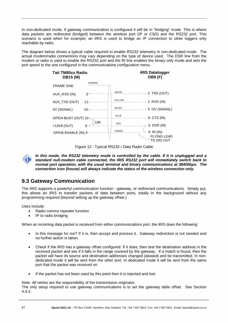
67 iQuest (NZ) Ltd - PO Box 15169, Hamilton, New Zealand Tel: +64 7 857-0810 Fax: +64 7 857-0811 Email: [email protected]
In non-dedicated mode, if gateway communication is configured it will be in “bridging” mode. This is where data packets are redirected (bridged) between the wireless port (IP or CSD) and the RS232 port. This scenario is used when for example; an iRIS is used to bridge an IP connection to other loggers only reachable by radio. The diagram below shows a typical cable required to enable RS232 telemetry in non-dedicated mode. The actual modem/radio connections may vary depending on the type of device used. The DSR line from the modem or radio is used to enable the RS232 port and the RI line enables the binary only mode and sets the port speed to the one configured in the communications configuration menu.
Figure 12 - Typical RS232 / Data Radio Cable
In this mode, the RS232 telemetry mode is controlled by the cable. If it is unplugged and a standard null-modem cable connected, the iRIS RS232 port will immediately switch back to normal port operation, with the usual terminal and binary communications at 38400bps. The connection icon (house) will always indicate the status of the wireless connection only.
9.3 Gateway Communication The iRIS supports a powerful communication function - gateway, or redirected communications. Simply put, this allows an iRIS to transfer packets of data between ports, totally in the background without any programming required (beyond setting up the gateway offset.) Uses include:
Radio comms repeater function IP to radio bridging
When an incoming data packet is received from either communications port, the iRIS does the following:
Is this message for me? If it is, then accept and process it. Gateway redirection is not needed and no further action is taken.
Check if the iRIS has a gateway offset configured. If it does, then test the destination address in the
received packet and see if it falls in the range covered by the gateway. If a match is found, then the packet will have its source and destination addresses changed (aliased) and be transmitted. In non-dedicated mode it will be sent from the other port. In dedicated mode it will be sent from the same port that the packet was received on.
If the packet has not been used by this point then it is rejected and lost.
Note: All retries are the responsibility of the transmission originator. The only setup required to use gateway communications is to set the gateway table offset. See Section 4.4.3.
AUX_RXD (IN) 3
AUX_TXD (OUT) 11
0V (SIGNAL) 15
GPIO4 BUSY (OUT) 10
+13V8 (OUT) 8
WHITE
YELLOW
BLACK
BLUE
RED
2 RXD (IN)
3 TXD (OUT)
5 OV (SIGNAL)
8 CTS (IN)
6 DSR (IN)
FRAME GND
Tait TM80xx Radio DB15 (M)
iRIS Datalogger DB9 (F)
SCREEN
9 RI (IN)
10K
FLYING LEADTO DIG OUT
GPIO6 ENABLE (IN) 9 GREEN
iRIS Datalogger User Guide V1.50
68 iQuest (NZ) Ltd - PO Box 15169, Hamilton, New Zealand Tel: +64 7 857-0810 Fax: +64 7 857-0811 Email: [email protected]
9.3.1 Aliased Gateway explained The iRIS uses a gateway method called "Aliased Gateway Communication". In other words, it alters the destination and source addresses of a received packet before it is redirected back out via the gateway. The primary reason for this in a radio only situation is to completely separate radio communication paths between stations. This is to avoid a packet that has been redirected through an intermediate station being received and replied to by the far destination station at the same time. This might be due to unusual RF propagation conditions where direct communications is not normally achievable between the originator and destination stations but suddenly becomes possible. By addressing the original packet from the originating node (usually HydroTel™) to a notional (non-existent) number, the gateway iRIS can add an offset to the address (correcting to the real address) and pass it on to the distant node. Any directly received packet will now be ignored by the distant iRIS as the address will not match. 9.3.2 Gateway Example
An iRIS, set to address 14, is installed at a hilltop rainfall measuring site. This logger is within range of a GSM network and it uses GPRS IP communications with the HydroTel™ base. A second iRIS, which is set to address 67, is installed down in the valley at a water quality site. This site has no wireless network coverage, so a pair of low-power radios is used to link the two sites. Each radio connects to the RS232 port on its respective iRIS logger. The hilltop site uses a special cable (see Figure 12 above) to enable non-dedicated RS232 telemetry mode because it also has wireless connectivity. As the valley site has no modem, it is set to “RS232 only” telemetry mode and it uses a standard RS232 cable to connect to the radio. The HydroTel™ base computer (which has a communications address of 0) needs to access both iRIS loggers. To achieve this, the hilltop iRIS is enabled for gateway communication and for convenience its offset gateway is set to 1000. This means that the site will redirect any packet with a destination address between 1000 and 1099.
To enable alarm call-back from the iRIS at the valley site, its call-back address is also set to 1000 to cause the hilltop gateway logger to redirect messages to the HydroTel™ base. The only change at the HydroTel™ base is to set the address for the valley site to 1067 in the station configuration form, rather than its actual address of 67. The address gets changed as it passes through the gateway iRIS logger as described below.
This is what happens to the data packets during a typical requestresponse data conversation.
HydroTel™ sends a request packet to the valley site via GPRS (which has the same IP address as the hilltop site in HydroTel™). It is addressed to destination address 1067 from sender’s address 0.
The gateway logger matches the destination address (1067) to be in its gateway address range. The packet’s source and destination addresses are aliased by applying the gateway offset (1000). The gateway logger sends the aliased packet via the radio down to the remote iRIS. It is now
addressed to destination address 67 from sender’s address 1000.
The remote iRIS processes the request and sends back its response via the radio. This packet is addressed to HydroTel™ as destination address 1000 from the valley iRIS sender’s address of 67.
The gateway logger matches the destination address (1000) to be in its gateway address range. The packet’s source and destination addresses are aliased by applying the gateway offset (1000). The gateway logger sends the aliased packet via the GPRS network to the HydroTel™ base. It is
now addressed to destination address 0 from sender’s address 1067.

69 iQuest (NZ) Ltd - PO Box 15169, Hamilton, New Zealand Tel: +64 7 857-0810 Fax: +64 7 857-0811 Email: [email protected]
10 Troubleshooting
This section offers possible answers to common installation and/or configuration issues. 10.1 Can’t connect to the iRIS via the RS232 port Check that the PC application (iLink or terminal program such as HyperTerminal®) is set for the correct comms port and speed (38400bps). Also check that the iRIS is not in RS232 Only Telemetry mode. This is indicated by a solid black house icon with an ‘R’ symbol in it being displayed on the LCD. If it is in this telemetry mode, switch back to normal mode by pressing any key or if currently logged in, then log out by pressing Alt-Enter from a top level screen. Sees Section 9.2 for details on using RS232 Telemetry mode. 10.2 iRIS will not start when the battery is first connected Check that the battery voltage is at least 12.2V. The internal battery management hardware is designed to shut the unit down when the battery becomes discharged to a certain point. It will not restart unless the battery is deemed to have sufficient capacity for normal operation. 10.3 Pulse lost when iRIS connected to other equipment In almost all installations where an iRIS is connected in parallel with other equipment to share a common pulse input (e.g. from a flow meter) there has not been a detrimental effect, as the iRIS presents a relatively high impedance to the circuit. However, in the event that connecting an iRIS does cause pulse failure, try removing the debounce selection link for the appropriate input. This sets the input to electronic switching mode, even if the actual pulse source is a clean contact (reed switch or similar). See Section 3.5.5 for details on the digital inputs. 10.4 Unable to connect to a GPRS or 3G network SIM Card: Check the SIM card is active and enabled for IP connectivity service. APN: The unit must be configured for a valid APN that must also match the SIM account APN. Signal: The iRIS will not attempt to connect if the RSSI is 0 or 99. Use a higher gain antenna if the
signal strength is marginal. IP Settings: The iRIS will not attempt to connect unless both Socket A and Socket B settings are defined
for GPRS models. (IP addresses and port numbers are non-zero). If Socket A is not used (as in 3G), set it to the same values as Socket B.
See Appendix I for a list of the network settings for the iQuest APN or iQuest Global Data Network. 10.5 Unable to connect to a CDMA network Account: Check the account is active and the CDMA data service is enabled. Signal: The iRIS will not attempt to connect if the RSSI is 0 or 99. Use a higher gain antenna if the
signal strength is marginal. IP Settings: The iRIS will not attempt to connect unless Socket B settings are defined. (IP address and
port must both be non-zero). If Socket A is not used, set it to the same values as Socket B. See Appendix I for a list of the network settings for the iQuest APN or iQuest Global Data Network. 10.6 iRIS will not respond to SMS requests Account: Check the account is active and the SMS service is enabled. Power Mode: If full power save is selected, the wireless modem is shut down. Connection: If the iRIS is connected on an IP (GPRS or CDMA-1X) session, the SMS feature is
unavailable. Use a scheduled IP connection to minimise the time that SMS is unavailable. Voice Call: If an iRIS 3x0V is connected on a voice call, the SMS feature is unavailable.

iRIS Datalogger User Guide V1.50
70 iQuest (NZ) Ltd - PO Box 15169, Hamilton, New Zealand Tel: +64 7 857-0810 Fax: +64 7 857-0811 Email: [email protected]
10.7 iRIS will not answer CSD data calls Power Mode: If full power save is selected, the wireless modem is shut down. Connection: If the iRIS is connected on an IP (GPRS / CDMA-1X / 3G) session, the CSD feature is
unavailable. Use a scheduled IP connection to minimise the time that CSD is unavailable. Voice Call: If an iRIS 3x0V is connected on a voice call, the CSD feature is unavailable. 10.8 iRIS 3x0V answers a voice call, but no sound is heard If the iRIS is currently connected to the wireless network with an IP link (GPRS/CDMA-1X or 3G IP), the iRIS voice processing function is disabled. However the internal modem may answer the incoming call independently but have no audio available. Set the IP connectivity using the scheduler so that it has a high availability for voice (short on-line sessions). 10.9 CDMA iRIS 3x0V answers a voice call, but a modem sound is heard CDMA unit normally has only a single phone number. Determining whether it should answer as a voice or data call requires the voice capability to be fully enabled. Enable voice on at least one of the sensors in the Voice menu (option 9 on the Main menu). 10.10 Logged data limits at a value like 32767 The iRIS stores data as a signed 16-bit integer value which has a range from -32768 to +32767. To adjust the actual measured value for storage, a logging multiplier is applied. If the measured value multiplied by this factor exceeds 32767, the stored value will limit at that point. Note that the result may be a number like 32.767 after it has been scaling by the unloading application (HydroTel, iLink etc). See Section 4.4.8 for details on using the logging multiplier. 10.11 Unable to access terminal menu If the security code has been enabled and this is unknown, then access is not possible. Please contact the person responsible for setting the code in the first instance. The code is set by an authorised user using iLink. However, if the security code is known and yet access is still denied, check the case of the entry is correct. E.g. Caps Lock key is not on. The code is case-sensitive and must match exactly... See Section 4.2 for details on the security code. 10.12 Digital output activates when user is logged on This is normal behaviour. The reason this happens is to enable easy sensor calibration or radio communication testing when the sensor or radio is controlled by a scheduled digital output. Otherwise the person on site would have to wait until the next scheduled operation to be able to perform the test.
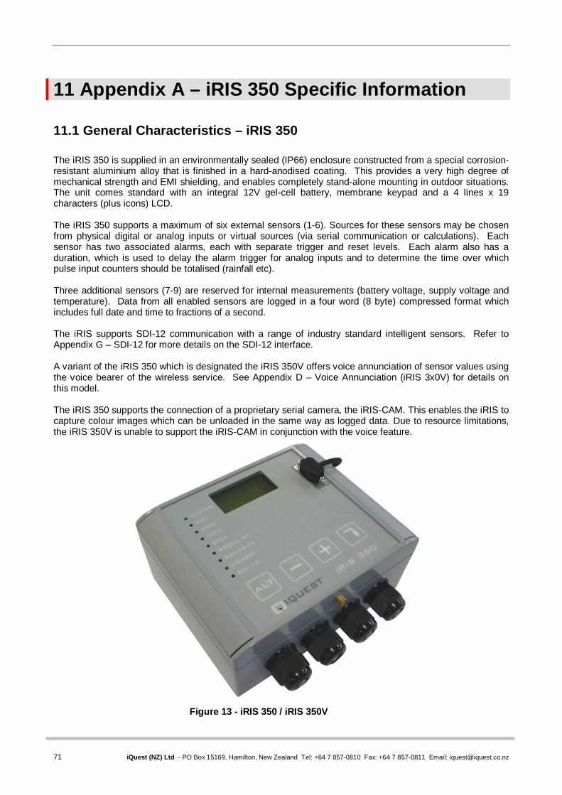
71 iQuest (NZ) Ltd - PO Box 15169, Hamilton, New Zealand Tel: +64 7 857-0810 Fax: +64 7 857-0811 Email: [email protected]
11 Appendix A – iRIS 350 Specific Information
11.1 General Characteristics – iRIS 350 The iRIS 350 is supplied in an environmentally sealed (IP66) enclosure constructed from a special corrosion-resistant aluminium alloy that is finished in a hard-anodised coating. This provides a very high degree of mechanical strength and EMI shielding, and enables completely stand-alone mounting in outdoor situations. The unit comes standard with an integral 12V gel-cell battery, membrane keypad and a 4 lines x 19 characters (plus icons) LCD. The iRIS 350 supports a maximum of six external sensors (1-6). Sources for these sensors may be chosen from physical digital or analog inputs or virtual sources (via serial communication or calculations). Each sensor has two associated alarms, each with separate trigger and reset levels. Each alarm also has a duration, which is used to delay the alarm trigger for analog inputs and to determine the time over which pulse input counters should be totalised (rainfall etc). Three additional sensors (7-9) are reserved for internal measurements (battery voltage, supply voltage and temperature). Data from all enabled sensors are logged in a four word (8 byte) compressed format which includes full date and time to fractions of a second. The iRIS supports SDI-12 communication with a range of industry standard intelligent sensors. Refer to Appendix G – SDI-12 for more details on the SDI-12 interface. A variant of the iRIS 350 which is designated the iRIS 350V offers voice annunciation of sensor values using the voice bearer of the wireless service. See Appendix D – Voice Annunciation (iRIS 3x0V) for details on this model. The iRIS 350 supports the connection of a proprietary serial camera, the iRIS-CAM. This enables the iRIS to capture colour images which can be unloaded in the same way as logged data. Due to resource limitations, the iRIS 350V is unable to support the iRIS-CAM in conjunction with the voice feature.
Figure 13 - iRIS 350 / iRIS 350V

iRIS Datalogger User Guide V1.50
72 iQuest (NZ) Ltd - PO Box 15169, Hamilton, New Zealand Tel: +64 7 857-0810 Fax: +64 7 857-0811 Email: [email protected]
11.2 Technical Specifications – iRIS 350 / iRIS 350V Dimensions: 117mm x 162mm x 67mm (4.60in x 6.37in x 2.64in) (Excluding glands and mounting plate) Mass: 1450g (3.19lb) with gel-cell battery fitted. Power Supply: Internal 12V @ 0.8A/Hr rechargeable sealed lead acid battery. Can also connect an
external regulated 12V dc power supply or rechargeable sealed lead-acid battery. Charger Supply: External 15-30Vdc supply. Supports a directly connected solar panel (no regulator). Power Consumption: Less than 3mA @ 12V in idle mode. Actual current consumption is dependent on
power management mode, wireless modem state and I/O configuration. Comms Interfaces: 1x RS232 DB9, 38,400 bps, DTE configuration.
1x Integral multi-band GSM/GPRS modem or 1x Integral HSDPA (3G®) modem
Digital I/O: 4 x Digital Inputs/Outputs. Each channel configurable as either an input or output. (Initial software fixes these as two inputs and two outputs – iRIS 320 emulation) Digital Input Mode:
- 30Vdc maximum input, switch to 0Vdc to activate. - Link selectable for either mechanical (<20Hz) or electronic (<5kHz) switching. Digital Output Mode: When set for output, the channel can be either: - Switched 12V out (max 100mA) or - Open-drain pull-down (max 100mA @ 30V)
Analog I/O: 4 x 16 bit uni-polar analog inputs. Range 0 – 5.000V. Input impedance 98kΩ.
Referenced to 0V common. Internal measurements available for monitoring are: Battery Voltage Supply Voltage Internal Temperature (C or F) Received Signal Strength (RSSI or RSCP) Link selectable for either voltage (0-5V) or current (0-20mA) mode. Integral
current mode resistor value 100R.
SDI-12 Interface: SDI-12 hardware interface that fully complies with the SDI-12 electrical standard. Software support to SDI-12 standard 1.2.
Logging Memory: Non-volatile 8MB flash storage of 1,085,476 time/date stamped data points. Circular
buffer mode (overwrites oldest data when memory full). A typical site with 2 parameters logged every 15 minutes plus battery voltage logged hourly will give 3.3 years of storage before data overwrite occurs.
Audio Memory: iRIS 350V only. Non-volatile 8MB flash storage of PCM audio files. Total
cumulative playtime 12 minutes at 11.025kHz sampling rate. Clock/Calendar: Non-volatile with user replaceable lithium back-up battery module. Y2K compliant
with leap year recognition. Accurate to +/-20 secs month, trimmable via a configuration register.
Mounting: 4 x M4 (3/16”) blind mounting holes in rear of case.
4 x 16mm (¾”) compression glands for power supply and I/O cabling access. Environmental: Storage Temperature: -20C - +85C. (-4F - +185F) Operating Temperature: -10C - +70C. (14F - +158F)
Enclosure sealed to IP66 with gasket and glands.

73 iQuest (NZ) Ltd - PO Box 15169, Hamilton, New Zealand Tel: +64 7 857-0810 Fax: +64 7 857-0811 Email: [email protected]
11.3 Mounting – iRIS 350 / iRIS 350V The iRIS can be mounted by installing suitable screws through the mounting pillars which are exposed when the lid is opened. The recommended mounting screws are M4 machine screws or Twinfast® wood screws.
It is very important that the four screws retaining the lid are tightened firmly after installation to maintain the IP66 rating of the enclosure.
Figure 14 - iRIS 350 / iRIS 350V Mounting Diagram
The mounting holes are on 142mm (5.11in) width by 80mm (3.2in) height centres.
11.4 Antenna Connection The iRIS 350 has an industry standard SMA connector which protrudes through the bottom edge of the enclosure lid. In areas of good signal strength, a small “stubby” or omni-directional type antenna will suffice. In areas of more marginal coverage, the antenna should an external high gain type such as a Yagi, via appropriate low-loss high frequency coaxial cable and male SMA connector.

iRIS Datalogger User Guide V1.50
74 iQuest (NZ) Ltd - PO Box 15169, Hamilton, New Zealand Tel: +64 7 857-0810 Fax: +64 7 857-0811 Email: [email protected]
12 Appendix B – iRIS 220 Specific Information
12.1 General Characteristics – iRIS 220 The iRIS 220 is supplied in a lightweight extruded aluminium enclosure finished in a resilient powder coating. This enclosure provides mechanical strength and EMI shielding, and also enables easy mounting in a variety of situations. The iRIS 220 supports a maximum of six external sensors (1-6). Sources for these sensors may be chosen from physical digital or analog inputs or virtual sources (via serial communication or internal calculations). Each sensor has two associated alarms, each with separate trigger and reset levels. Each alarm also has a duration, which is used to delay the alarm trigger for analog inputs and to determine the time over which pulse input counters should be totalised (for rainfall etc). Three additional sensors (7-9) are reserved for internal measurements (battery voltage, supply voltage and logger temperature). Data from all enabled sensors are logged in a four word (8 byte) compressed format which includes full date and time to fractions of a second.
Figure 15 - iRIS 220

75 iQuest (NZ) Ltd - PO Box 15169, Hamilton, New Zealand Tel: +64 7 857-0810 Fax: +64 7 857-0811 Email: [email protected]
12.2 Technical Specifications – iRIS 220 Dimensions: 100mm x 172mm x 40mm (3.93in x 6.77in x 1.57in) (Excluding connectors) Mass: 380g (13.4oz) Power Supply: External regulated 12V dc power supply or rechargeable sealed lead-acid battery. Charger Source - External 15-30V dc supply. Supports a directly connected solar
panel (no regulator required). Power Consumption: Less than 3mA @ 12V in idle mode and full power save mode selected.
Actual current consumption is dependent on power management mode, wireless modem state and I/O configuration.
Comms Interfaces: 1x RS232 DB9, 38400 bps, DTE configuration.
1x Integral dual-band (900/1800MHz) GSM/GPRS modem or Integral single-band (1900MHz) GSM/GPRS modem or Integral CDMA/CDMA-1X modem or Integral HSDPA (3G) modem
Digital I/O: 2 x Digital Inputs
- 30Vdc maximum input, switch to 0Vdc to activate. - Link selectable for either mechanical (<20Hz) or electronic (<5kHz) switching. 2 x Digital Outputs - 1 x Open-drain pull-down (max 300mA @ 30V) - 1 x Switched 12V out (max 300mA)
Analog I/O: 4 x 12 bit uni-polar analog inputs. Range 0-5000mV. Input impedance 98kΩ.
Referenced to 0V common. Internal measurements available for monitoring are: Battery Voltage Supply Voltage Internal Temperature (C or F) Received Signal Strength Indication (RSSI)
Logging Memory: Non-volatile 2MB flash storage of 262,144 time/date stamped data points. Circular
buffer mode (overwrites oldest data when memory is full). A typical site with 2 parameters logged every 15 minutes plus battery voltage logged hourly will give 3.3 years of storage before data overwrite occurs.
Clock/Calendar: Non-volatile with integral lithium back-up battery. Leap year recognition. Accurate to
+/-20 secs month, trimmable via a configuration register. Mounting: 4 x M4 (3/16”) mounting holes at ends of case. Environmental: Storage Temperature: -20C - +85C. (-4F - +185F) Operating Temperature: -10C - +70C. (14F - +158F)

iRIS Datalogger User Guide V1.50
76 iQuest (NZ) Ltd - PO Box 15169, Hamilton, New Zealand Tel: +64 7 857-0810 Fax: +64 7 857-0811 Email: [email protected]
12.3 Mounting – iRIS 220 An outline of the iRIS 220 case is shown below. The recommended mounting screws are M4 machine screws or Twinfast® wood screws.
Figure 16 - iRIS 220 Mounting Diagram
12.4 Antenna Connection The iRIS 220 antenna connects to a female BNC connector that protrudes through one end plate of the case. In areas of good signal strength, a small “stubby” or omni-directional type antenna will suffice. In areas of more marginal coverage, the antenna should an external high gain type such as a Yagi, via appropriate low-loss high frequency coaxial cable and male SMA connector.
150 mm
80 mm

77 iQuest (NZ) Ltd - PO Box 15169, Hamilton, New Zealand Tel: +64 7 857-0810 Fax: +64 7 857-0811 Email: [email protected]
13 Appendix C – iRIS 320 Specific Information
13.1 General Characteristics – iRIS 320 The iRIS 320 is supplied in an environmentally sealed (IP65) enclosure constructed from a special corrosion-resistant aluminium alloy that is finished in a hard-anodised coating. This provides a very high degree of mechanical strength and EMI shielding, and enables completely stand-alone mounting in outdoor situations. The unit comes standard with an integral 12V gel-cell battery, membrane keypad and a 4 lines x 12 characters (plus icons) LCD. The iRIS 320 supports a maximum of six external sensors (1-6). Sources for these sensors may be chosen from physical digital or analog inputs or virtual sources (via serial communication or calculations). Each sensor has two associated alarms, each with separate trigger and reset levels. Each alarm also has a duration, which is used to delay the alarm trigger for analog inputs and to determine the time over which pulse input counters should be totalised (rainfall etc). Three additional sensors (7-9) are reserved for internal measurements (battery voltage, supply voltage and temperature). Data from all enabled sensors are logged in a four word (8 byte) compressed format which includes full date and time to fractions of a second. The iRIS supports SDI-12 communication with a range of industry standard intelligent sensors. Refer to Appendix G – SDI-12 for more details on the SDI-12 interface. A variant of the iRIS 320 which is designated the iRIS 320V offers voice annunciation of sensor values using the voice bearer of the wireless service. See Appendix D – Voice Annunciation (iRIS 3x0V) for details on this model. The iRIS 320 (from PCB revision 1.2) is able to manage a serial camera, the iRIS-CAM (via a small adaptor module). This enables the iRIS to capture colour images which can be unloaded in the same way as logged data. Due to resource limitations, the iRIS 320V is unable to support the iRIS-CAM in conjunction with the voice feature.
Figure 17 - iRIS 320 / iRIS 320V

iRIS Datalogger User Guide V1.50
78 iQuest (NZ) Ltd - PO Box 15169, Hamilton, New Zealand Tel: +64 7 857-0810 Fax: +64 7 857-0811 Email: [email protected]
13.2 Technical Specifications – iRIS 320 / iRIS 320V Dimensions: 117mm x 162mm x 67mm (4.60in x 6.37in x 2.64in) (Excluding glands and mounting plate) Mass: 1580g (3.48lb) Power Supply: Internal 12V @ 0.8A/Hr rechargeable sealed lead acid battery. Can also connect an
external regulated 12V dc power supply or rechargeable sealed lead-acid battery. Charger Supply: External 15-30Vdc supply. Supports a directly connected solar panel (no regulator). Power Consumption: Less than 3mA @ 12V in idle mode. Actual current consumption is dependent on
power management mode, wireless modem state and I/O configuration. Comms Interfaces: 1x RS232 DB9, 38,400 bps, DTE configuration.
1x Integral dual-band (900/1800MHz) GSM/GPRS modem or Integral single-band (1900MHz) GSM/GPRS modem or Integral CDMA/CDMA-1X modem or Integral HSDPA (3G) modem
Digital I/O: 2 x Digital Inputs
- 30Vdc maximum input, switch to 0Vdc to activate. - Link selectable for either mechanical (<20Hz) or electronic (<5kHz) switching. 2 x Digital Outputs - 1 x Switched 12V out (max 300mA) - 1 x Open-drain pull-down (max 300mA @ 30V)
Analog I/O: 4 x 12 bit uni-polar Analog inputs. Range 0-5000mV. Input impedance 98kΩ.
Referenced to 0V common. Internal measurements available for monitoring are: Battery Voltage Supply Voltage Internal Temperature (C or F) Received Signal Strength (RSSI)
SDI-12 Interface: SDI-12 hardware interface that fully complies with the SDI-12 electrical standard.
Software support to SDI-12 standard 1.2. Logging Memory: Non-volatile 2MB flash storage of 262,144 time/date stamped data points. Circular
buffer mode (overwrites oldest data when memory full). A typical site with 2 parameters logged every 15 minutes plus battery voltage logged hourly will give 3.3 years of storage before data overwrite occurs.
Audio Memory: iRIS 320V only. Non-volatile 2MB flash storage of PCM audio files. Total
cumulative playtime 3 minutes at 11.025kHz sampling rate. Clock/Calendar: Non-volatile with integral lithium back-up battery. Y2K compliant with leap year
recognition. Accurate to +/-20 secs month, trimmable via a configuration register. Mounting: 4 x M4 (3/16”) blind mounting holes in rear of case. Mounting plate supplied as
standard accessory for wall or panel installation. 2 x 16mm (¾”) compression glands for power supply and I/O cabling access. 1 x 25mm (1”) compression gland for antenna / RF cable access Front secured by three M5 Allen Key® screws. The two (left-hand) screws act as hinge links. The third (right-hand) screw can be locked with a tamper-proof wire seal.
Environmental: Storage Temperature: -20C - +85C. (-4F - +185F) Operating Temperature: -10C - +70C. (14F - +158F)
Enclosure sealed to IP65 with gasket and glands.

79 iQuest (NZ) Ltd - PO Box 15169, Hamilton, New Zealand Tel: +64 7 857-0810 Fax: +64 7 857-0811 Email: [email protected]
13.3 Mounting – iRIS 320 / iRIS 320V An outline of the iRIS 320 mounting plate is shown below. The recommended mounting screws are M4 machine screws or Twinfast® wood screws. NOTE: It is very important that the three M5 Allen Key® screws on the front panel are tightened firmly after installation to maintain the IP65 rating of the enclosure.
Figure 18 - iRIS 320 / iRIS 320V Mounting Diagram
The mounting holes are on 130mm (5.11in) width by 82mm (3.22in) height centres.
13.4 Antenna Connection The iRIS 320 / iRIS 320V antenna is fitted through a compression gland in the bottom of the case. Internally, the antenna terminates at a female BNC connector on the circuit board. In areas of good signal strength, a small “stubby” or omni-directional type antenna will suffice. In areas of more marginal coverage, the antenna should an external high gain type such as a Yagi, via appropriate low-loss high frequency coaxial cable and male SMA connector.

iRIS Datalogger User Guide V1.50
80 iQuest (NZ) Ltd - PO Box 15169, Hamilton, New Zealand Tel: +64 7 857-0810 Fax: +64 7 857-0811 Email: [email protected]
14 Appendix D – Voice Annunciation (iRIS 3x0V)
The iRIS 3x0 can be supplied with a voice annunciation feature. In this case it is then allocated the designation, iRIS 3x0V. Typically the voice annunciation feature is used to play back the current values of all enabled sensors when the unit is called up from a telephone. To maintain high quality, natural sounding audio, including support for almost any language, the iRIS 3x0V uses standard PCM (Pulse Code Modulation) sound files. These are stored in the unit in a dedicated flash memory device. The files are standard 8-bit, mono, 11.025kHz wave files and loaded into the iRIS 3x0V using the Audio Manager function in iLink.
All iRIS 3x0V units are supplied initially with a default set of sound files pre-loaded and these can be used/modified/replaced as necessary by following the directions in the later part of this section.
To optimise the speed of operation against the available memory, the audio file storage has been divided into four “partitions”, each able to hold a fixed number of files that can be easily indexed by the iRIS 3x0V controller. The partitioning has been designed to allow sufficient space for future bilingual voice support. Currently, only the first half of each partition is used. The second language option will use the second block of messages in each partition. E.g. Partition 0, Messages 1-22 are for language 1, Messages 23-44 will be for language 2. Partition Function Max File Length Number of Files
0 Standard Sounds 1 second 44 1 Sensor Units 2 seconds 18 2 Sensor Names 3 seconds 18 3 Site Name / Misc Instructions 5 seconds 12
Partition 0 This partition holds the standard sound files for the digits 0-9, a decimal point and minus. These are used to create the reported measurement values. This partition should be loaded with the appropriate files containing the local words for the following numeric values: Message 1: “One” Message 11: “Point” Message 21: spare Message 2: “Two” Message 12: “Minus” Message 22: spare Message 3: “Three” Message 13: spare Message 4: “Four” Message 14: spare Message 5: “Five” Message 15: spare Message 6: “Six” Message 16: spare Message 7: “Seven” Message 17: spare Message 8: “Eight” Message 18: spare Message 9: “Nine” Message 19: spare Message 10: “Zero” Message 20: spare Partition 1 This partition holds the specific sound files for the units of the nine sensors. For example, if Sensor 3 is measuring air temperature in °C, then the file loaded into Partition 1, Message 3 should contain the local language phrase for “Degrees Celsius”. Messages 1-9: Sensor Units for Sensors 1-9 respectively. Partition 2 This partition holds the specific sound files for the measurement names of the nine sensors. For example, if Sensor 3 is measuring air temperature in °C, then the file loaded into Partition 2, Message 3 should contain the local language name for “Air Temperature”.
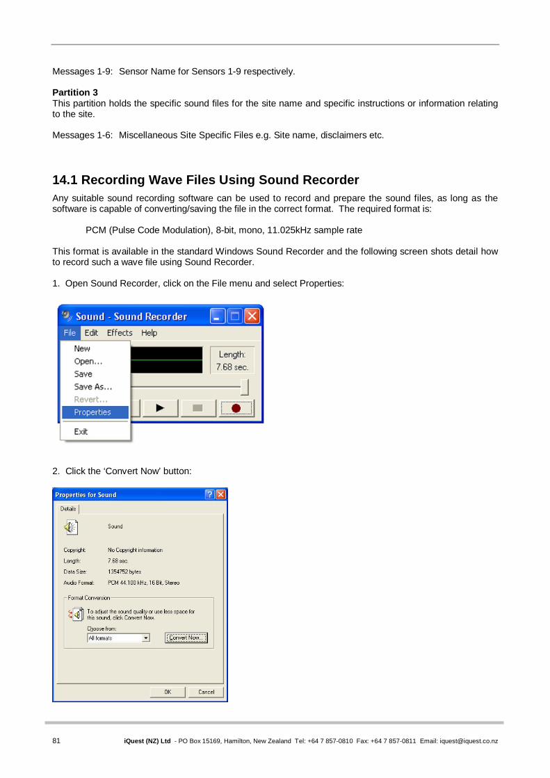
81 iQuest (NZ) Ltd - PO Box 15169, Hamilton, New Zealand Tel: +64 7 857-0810 Fax: +64 7 857-0811 Email: [email protected]
Messages 1-9: Sensor Name for Sensors 1-9 respectively. Partition 3 This partition holds the specific sound files for the site name and specific instructions or information relating to the site. Messages 1-6: Miscellaneous Site Specific Files e.g. Site name, disclaimers etc. 14.1 Recording Wave Files Using Sound Recorder Any suitable sound recording software can be used to record and prepare the sound files, as long as the software is capable of converting/saving the file in the correct format. The required format is:
PCM (Pulse Code Modulation), 8-bit, mono, 11.025kHz sample rate This format is available in the standard Windows Sound Recorder and the following screen shots detail how to record such a wave file using Sound Recorder. 1. Open Sound Recorder, click on the File menu and select Properties:
2. Click the ‘Convert Now’ button:

iRIS Datalogger User Guide V1.50
82 iQuest (NZ) Ltd - PO Box 15169, Hamilton, New Zealand Tel: +64 7 857-0810 Fax: +64 7 857-0811 Email: [email protected]
3. Select the Name as “Telephone Quality” from the drop-down list and check that the Format is “PCM”. If this is not the case, select it from the drop-down list.
4. Change the Attributes by selecting ‘11.025kHz, 8 bit, Mono 10 kb/sec’ from the drop-down list.
The Name will change to [Untitled]. There is no need to be concerned about this. 4. Click on OK to close the dialog box, and then click on OK again to close the properties box.
5. Click the Record button to begin recording your message. For multiple messages, it is often more efficient to record several in one “master” message with appropriate gaps, then cut and trim the individual messages from that original file. See 9 below.
7. When you have finished recording, click the Stop button. 8. It is a good idea to play back the message to check the quality and clarity of the sound. 9. Usually, you will need to trim the sound file so that it fits in the designated partition and message slot (refer to the table above for the maximum permitted message lengths). This can be done by deleting a section of the file at the beginning and end of the message.

83 iQuest (NZ) Ltd - PO Box 15169, Hamilton, New Zealand Tel: +64 7 857-0810 Fax: +64 7 857-0811 Email: [email protected]
10. To delete a section of the message at the start, play the message back until you reach the point that you wish to delete up to. This can be fine-adjusted by dragging the slider bar if necessary. Then click on the Edit menu and choose ‘Delete before current position’. You will be asked to confirm the deletion. Click ‘OK’ to confirm and the portion of the message up to the current point will be deleted.
11. This same process can be used to delete a section from the end of the message, but using ‘Delete after current position’ instead. 12. The file can then be saved, ready for uploading to the iRIS 3x0V, by clicking on the File menu and selecting ‘Save As’. 14.2 Loading Wave Files into the iRIS iLink incorporates an Audio Manager form which is designed for uploading single or multiple audio files to an iRIS 3x0V. The Audio Manager is accessed by selecting [Tools][Advanced][Audio Manager] from the main menu and is shown in the following screenshot:
The page is split into two separate areas, Audio File and Audio Script. The Audio File settings are used to playback and/or upload individual files to an iRIS 3x0V. The Audio Script settings are used to validate and/or upload multiple sound files.
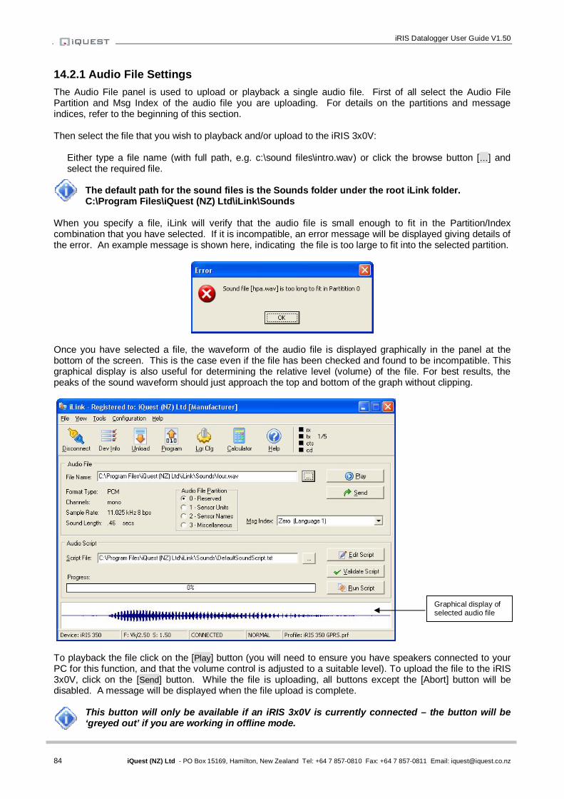
iRIS Datalogger User Guide V1.50
84 iQuest (NZ) Ltd - PO Box 15169, Hamilton, New Zealand Tel: +64 7 857-0810 Fax: +64 7 857-0811 Email: [email protected]
14.2.1 Audio File Settings The Audio File panel is used to upload or playback a single audio file. First of all select the Audio File Partition and Msg Index of the audio file you are uploading. For details on the partitions and message indices, refer to the beginning of this section. Then select the file that you wish to playback and/or upload to the iRIS 3x0V:
Either type a file name (with full path, e.g. c:\sound files\intro.wav) or click the browse button […] and select the required file.
The default path for the sound files is the Sounds folder under the root iLink folder. C:\Program Files\iQuest (NZ) Ltd\iLink\Sounds
When you specify a file, iLink will verify that the audio file is small enough to fit in the Partition/Index combination that you have selected. If it is incompatible, an error message will be displayed giving details of the error. An example message is shown here, indicating the file is too large to fit into the selected partition.
Once you have selected a file, the waveform of the audio file is displayed graphically in the panel at the bottom of the screen. This is the case even if the file has been checked and found to be incompatible. This graphical display is also useful for determining the relative level (volume) of the file. For best results, the peaks of the sound waveform should just approach the top and bottom of the graph without clipping.
To playback the file click on the [Play] button (you will need to ensure you have speakers connected to your PC for this function, and that the volume control is adjusted to a suitable level). To upload the file to the iRIS 3x0V, click on the [Send] button. While the file is uploading, all buttons except the [Abort] button will be disabled. A message will be displayed when the file upload is complete.
This button will only be available if an iRIS 3x0V is currently connected – the button will be ‘greyed out’ if you are working in offline mode.
Graphical display of selected audio file

85 iQuest (NZ) Ltd - PO Box 15169, Hamilton, New Zealand Tel: +64 7 857-0810 Fax: +64 7 857-0811 Email: [email protected]
14.2.2 Audio Script Settings The Audio Script panel is used to edit, validate and upload audio scripts. An audio script is a list of audio files together with an associated partition and message index number. For information on partitions and message indices refer to the beginning of this Section. An example audio script, DefaultSoundScript.txt is included with the iLink installation and can be used as a base template for creating other script files. The DefaultSoundScript file contains the following entries: 0,1,zero 0,2,one 0,3,two 0,4,three 0,5,four 0,6,five 0,7,six 0,8,seven 0,9,eight 0,10,nine 0,11,point 0,12,minus 1,1,metres 1,2,pause 1,3,pause 1,4,pause 1,5,pause 1,6,pause 1,7,volts 1,8,volts 1,9,degc
2,1,waterlevel 2,2,pause 2,3,pause 2,4,pause 2,5,pause 2,6,pause 2,7,battery 2,8,solarvolts 2,9,temperature 3,1,site 3,2,pause
Each row contains three settings:
The partition number The message index The name of the sound file
The sound file name does not have the .wav extension included, to simplify the script.
The first line in the DefaultSoundScript file shown here indicates that a file named zero.wav should be loaded into partition 0, message index 1.
All the sound files to be used in the script must be located in the ‘Sounds’ subfolder located in the iLink application folder.
The script file can contain as few or as many entries as required. Only locations (partition number and message index) that you wish to modify need to be included in the script file. In the example file shown above, messages 1-12 are updated for partition 0 along with messages 1-9 for partition 1, messages 1-9 for partition 2 and messages 1 and 2 for partition 3. All other locations are left unchanged within the iRIS 3x0V, i.e. any files that are currently stored in these locations will remain after the script has been run. In practice it is useful to create a ‘standard’ script file that lists the locations and audio files for the digits, and then create a series of ‘site specific’ scripts that contain the locations and wave file for the sensors, units and site name etc. Validating Audio Script Files Once you have selected an audio script, you should click the [Validate Script] button to verify that the script dos not contain any errors. Possible errors might include syntax errors, the wrong number of parameters on a line, a wave file that does not exist or a wave file that is incompatible with the specified partition. As iLink scans the script file, each of the specified wave files is selected into the Audio Panel (see earlier) and scanned for compatibility. The associated waveform is also displayed in the bottom panel as each file is processed. Once the verification process is complete, a message box will be displayed indicating either a successful scan, or the first error encountered. If an error is encountered, the details are displayed and will need to be corrected before the script can be run. Editing Script Files Script files are just plain text files and so they can be edited from any suitable text editor such as WindowsTM Notepad. If a script file has been selected in the iLink Audio Manager, clicking on the [Edit Script] button will launch Notepad with the selected script file loaded, ready for editing. Remember to save any changes before closing Notepad and returning to the Audio Manager.

iRIS Datalogger User Guide V1.50
86 iQuest (NZ) Ltd - PO Box 15169, Hamilton, New Zealand Tel: +64 7 857-0810 Fax: +64 7 857-0811 Email: [email protected]
Running an Audio Script File Once a script file has been selected and verified, click on the [Run Script] button to execute the script which will upload each of the specified audio files to the iRIS 3x0V. As each line of the script is processed, the top panel (Audio File Panel) reflects the current audio file, partition and index number, and the bottom panel displays the audio file waveform in a graphical format. When the script has completed, a message will be displayed confirming that the upload procedure is complete. 14.2.3 Uploading Audio Files over a Remote Connection It is possible to upload audio files to an iRIS 3x0V that is connected to iLink over a radio or GPRS link. However due to the potentially large file sizes involved, it is highly recommended that all audio uploads are carried out with the logger connected directly to the PC via the RS232 port. Also, if communication to the logger is lost during a script-based audio upload, the results may be indeterminable as files may be only partially loaded so remote uploads should be carried out with caution and only considered where a local connection is not possible.

87 iQuest (NZ) Ltd - PO Box 15169, Hamilton, New Zealand Tel: +64 7 857-0810 Fax: +64 7 857-0811 Email: [email protected]
15 Appendix E - Using an iRIS-CAM Camera
15.1 Overview The iRIS-CAM is a camera accessory for the iRIS 320 and iRIS 350 datalogger. It is supplied in an environmentally sealed (IP66) enclosure constructed from a special corrosion-resistant aluminium alloy that is finished in a hard-anodised coating. This provides a very high degree of mechanical strength and EMI shielding, and enables completely stand-alone mounting in outdoor situations. The enclosure is filled with epoxy resin and the lens is silicon greased in place, which means the potential for water ingress is extremely low. When connected to an appropriately configured iRIS data logger, images can be taken, stored and then unloaded (at regular intervals) via any of the communication channels available to the iRIS (e.g. IP, CSD or RS232).
To use an iRIS-CAM, an iRIS 320 requires a small interface board to be installed. The iRIS 350 has the interface already built in.
15.2 Specifications SIZE: 162mm x 116mm x 65mm (4.60in x 6.37in x 2.64in) (WxHxD) CONNECTORS: 6 way rectangular connector on the end of 5m of shielded PVC cable. MASS: 300 g (10.6oz) POWER SUPPLY: 3.3V d.c +/- 10% (powered via cable from iRIS) RESOLUTION: Selectable 80x60, 160x128, 350x240 or 640x480 pixels, JPEG format,
24-bit colour STANDARD LENS: F2.8
Focal length 4mm Integral IR filter
ENVIRONMENTAL: Operating: -10 °C to +70 °C (14 °F to +158 °F)
Storage: -10 °C to +85 °C (14 °F to +185 °F) Enclosure sealed to IP66

iRIS Datalogger User Guide V1.50
88 iQuest (NZ) Ltd - PO Box 15169, Hamilton, New Zealand Tel: +64 7 857-0810 Fax: +64 7 857-0811 Email: [email protected]
15.3 Mounting This can be achieved with the use of the four M6 Allen Key® bolts or other suitable hardware such as wood screws. The diagram below shows the overall dimensions and position of the mounting holes for the IRIS-CAM. The correct orientation is shown in the diagram, where the engraved writing is the right way up. The cable extends from the left side of the enclosure when viewing the camera from the front.
Due to the lens’s small aperture it can be susceptible to image quality degradation due to droplet of water (which creates a second lens). To minimize the effects, provide the camera lens with a rain shield; position the camera so that it points down and away from prevailing weather.

89 iQuest (NZ) Ltd - PO Box 15169, Hamilton, New Zealand Tel: +64 7 857-0810 Fax: +64 7 857-0811 Email: [email protected]
15.4 Connecting the iRIS-CAM Connecting the camera to the datalogger is a simple process. First disconnect all power to the logger then feed the camera cable through the gland. Next connect the iRIS-CAM 6 way connector to the camera port on the iRIS circuit board. This is located next to the SIM card carrier on the iRIS 350. For the iRIS 320 model, install the camera adaptor PCB and connect the camera to the port on the adaptor. Finally tighten the gland and re-power the logger. The easiest way to commission the iRIS-CAM is to connect it to the USB port of a laptop or desktop PC. This allows quick and repetitive collection of images from the camera, enabling quick focusing and alignment of the camera.
It is important to install the Windows® iRIS-CAM USB adapter drivers before connecting the camera to the PC.
15.5 Installing PC Based Software & USB Drivers The following list of steps will install the iRISCamera commissioning software and the Windows® USB drivers for the iRIS-CAM adaptor.
1. Obtain the installation package from iQuest.1
2. For the CD distribution: a. Insert CD into PC’s CDROM drive. If the installer does not automatically start, then run it
manually from d:\ iRISCAMInstaller.exe (where d:\ is the CDROM drive letter). b. Click on Install iRIS-CAM button and follow the prompts.
3. For a Web download:
a. Download the iRIS-CAM windows software installer package from www.iquest.co.nz b. Run the iRISCAMInstaller.exe program and follow the instructions.
4. Once installation of the iRISCamera Software is complete and the installation program has been
closed, install the USB drivers by: a. Run the installer from Start->All Programs->iRIS-CAM->USB Driver Installer. b. Click Install button.
If you are prompted with the message saying the software has not passed Windows Logo
Verification, please ignore and click the Continue Anyway button.
1 Software can be obtained from CD or the iQuest website: www.iquest.co.nz
iRIS-CAM 6 way Connector on iRIS 350
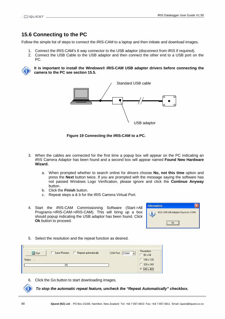
iRIS Datalogger User Guide V1.50
90 iQuest (NZ) Ltd - PO Box 15169, Hamilton, New Zealand Tel: +64 7 857-0810 Fax: +64 7 857-0811 Email: [email protected]
15.6 Connecting to the PC Follow the simple list of steps to connect the iRIS-CAM to a laptop and then initiate and download images.
1. Connect the iRIS-CAM’s 6 way connector to the USB adaptor (disconnect from iRIS if required). 2. Connect the USB Cable to the USB adaptor and then connect the other end to a USB port on the
PC.
It is important to install the Windows® iRIS-CAM USB adapter drivers before connecting the camera to the PC see section 15.5.
3. When the cables are connected for the first time a popup box will appear on the PC indicating an
iRIS Camera Adaptor has been found and a second box will appear named Found New Hardware Wizard.
a. When prompted whether to search online for drivers choose No, not this time option and
press the Next button twice. If you are prompted with the message saying the software has not passed Windows Logo Verification, please ignore and click the Continue Anyway button.
b. Click the Finish button. c. Repeat steps a & b for the iRIS Camera Virtual Port.
4. Start the iRIS-CAM Commissioning Software (Start->All Programs->iRIS-CAM->iRIS-CAM). This will bring up a box should popup indicating the USB adaptor has been found. Click Ok button to proceed.
5. Select the resolution and the repeat function as desired.
6. Click the Go button to start downloading images. To stop the automatic repeat feature, uncheck the “Repeat Automatically” checkbox.
USB adaptor
Standard USB cable
Figure 19 Connecting the iRIS-CAM to a PC.
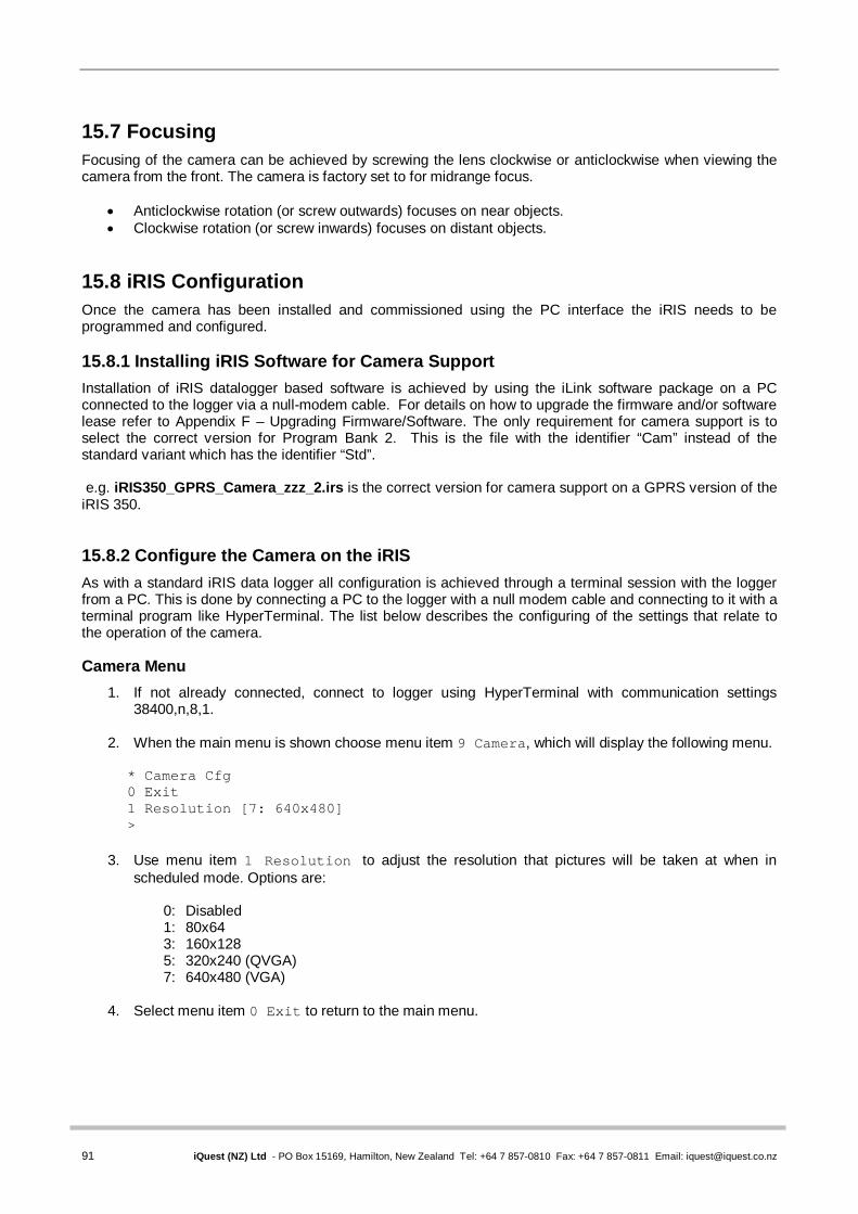
91 iQuest (NZ) Ltd - PO Box 15169, Hamilton, New Zealand Tel: +64 7 857-0810 Fax: +64 7 857-0811 Email: [email protected]
* Camera Cfg 0 Exit 1 Resolution [7: 640x480] >
15.7 Focusing Focusing of the camera can be achieved by screwing the lens clockwise or anticlockwise when viewing the camera from the front. The camera is factory set to for midrange focus.
Anticlockwise rotation (or screw outwards) focuses on near objects. Clockwise rotation (or screw inwards) focuses on distant objects.
15.8 iRIS Configuration Once the camera has been installed and commissioned using the PC interface the iRIS needs to be programmed and configured. 15.8.1 Installing iRIS Software for Camera Support Installation of iRIS datalogger based software is achieved by using the iLink software package on a PC connected to the logger via a null-modem cable. For details on how to upgrade the firmware and/or software lease refer to Appendix F – Upgrading Firmware/Software. The only requirement for camera support is to select the correct version for Program Bank 2. This is the file with the identifier “Cam” instead of the standard variant which has the identifier “Std”. e.g. iRIS350_GPRS_Camera_zzz_2.irs is the correct version for camera support on a GPRS version of the iRIS 350. 15.8.2 Configure the Camera on the iRIS As with a standard iRIS data logger all configuration is achieved through a terminal session with the logger from a PC. This is done by connecting a PC to the logger with a null modem cable and connecting to it with a terminal program like HyperTerminal. The list below describes the configuring of the settings that relate to the operation of the camera. Camera Menu
1. If not already connected, connect to logger using HyperTerminal with communication settings 38400,n,8,1.
2. When the main menu is shown choose menu item 9 Camera, which will display the following menu.
3. Use menu item 1 Resolution to adjust the resolution that pictures will be taken at when in
scheduled mode. Options are:
0: Disabled 1: 80x64 3: 160x128 5: 320x240 (QVGA) 7: 640x480 (VGA)
4. Select menu item 0 Exit to return to the main menu.

iRIS Datalogger User Guide V1.50
92 iQuest (NZ) Ltd - PO Box 15169, Hamilton, New Zealand Tel: +64 7 857-0810 Fax: +64 7 857-0811 Email: [email protected]
* Digital Output 1 Cfg 0 Exit 1 Enable [Yes] 2 Polarity [Normal] 3 Mode [1: Schedule] 4 Duration [10 sec] 5 Frequency [15 min] 6 Start Time [0525] 7 End Time [1959]
There are two ways of taking an image:
Scheduled – This method uses the Digital Output #1 schedule control to take pictures at regular intervals. Digital Output #1 is still triggered on the schedule, which means it can be used to control external illumination for the camera.
Remote – Use HydroTel™ to start a picture capture. Refer to the HydroTel documentation on how to
setup and use this feature. Scheduled Picture Capture Settings
1. Connect to logger using HyperTerminal with communication settings 38400,n,8,1 2. When the main menu is shown choose menu item 5 Outputs, which will display the outputs menu. 3. Select menu item 1 Output #1, which will display the following menu.
4. The important settings are as follows
Menu item 1: Yes. Menu item 3: 1: Schedule.
Menu item 4: 10 seconds. Menu item 5: How often the images are taken in minutes.
Menu item 6: Start taking images at this time (24 hour clock). Menu item 7: Stop taking images at this time (24 hour clock).
Remote Picture Capture Settings In this mode the iRIS-CAM will take a picture on request from a base station such as HydroTel™. There are no iRIS based settings required for this mode. Picture capture will happen automatically and can be used in conjunction with schedule mode.
Resolution of the remotely requested picture can be different to the scheduled one.

93 iQuest (NZ) Ltd - PO Box 15169, Hamilton, New Zealand Tel: +64 7 857-0810 Fax: +64 7 857-0811 Email: [email protected]
16 Appendix F – Upgrading Firmware/Software
16.1 Overview This section describes the procedure to use when upgrading the firmware/software components in an iRIS.
The upgrade procedure has been carried out many times without issue. However, because the process does involve erasing and reprogramming of flash memory, it is important that a good, securely connected power supply is provided to the iRIS throughout the upgrade process.
16.2 File Naming Conventions 16.2.1 iRIS Executive Firmware. The “Firmware” in the iRIS is analogous to the operating system in a PC. It is the Firmware that contains all the low level functions and library routines used by the Application Software. The iRIS firmware is available as a single file for downloading and flash upgrading using iLink. The upgrade file is in the format:
iRIS350_xxx.fls where:
xxx is the firmware version e.g. iRIS350_250.fls iRIS 350 Firmware, Version Vk/2.50 The default repository for the firmware files is the “Firmware” folder under iLink. 16.2.2 iRIS Application Software.
The “Application Software” in the iRIS is analogous to an application such as Word® on a PC. It is the software that contains the general functionality of the iRIS. This comes in three sections or “banks” (due to the memory configuration of the iRIS) but runs as it were one single program.
The common software upgrade files for Banks 1 and 3 are in the format:
iRIS350_xxxx_yyy_z.irs where: xxxx is the wireless module type (GPRS, CDMA, 3G, No Modem)
yyy is the software version z is the program bank that this file should be loaded into
e.g. iRIS350_GPRS_150_1.irs iRIS 350 Software, GPRS, Version 1.50, Bank 1
The file for Bank 2 can be different depending on the program variant. This means that the Bank 2 file has an extra field in its name. The default variant name is “Std” for the standard issue software.
e.g. iRIS350_3G_Std_150_2.irs iRIS 350 Software, 3G, Standard, Version 1.50, Bank 2
The default repository for the program files is the “Programs” folder under iLink.
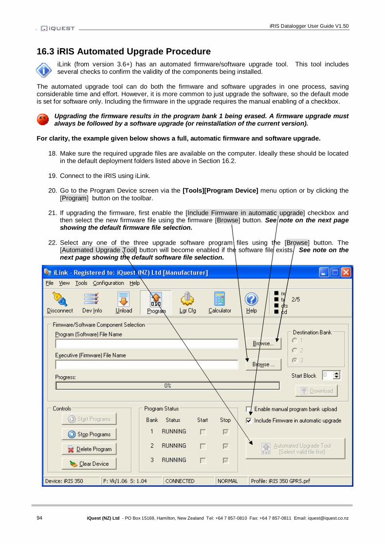
iRIS Datalogger User Guide V1.50
94 iQuest (NZ) Ltd - PO Box 15169, Hamilton, New Zealand Tel: +64 7 857-0810 Fax: +64 7 857-0811 Email: [email protected]
16.3 iRIS Automated Upgrade Procedure iLink (from version 3.6+) has an automated firmware/software upgrade tool. This tool includes several checks to confirm the validity of the components being installed.
The automated upgrade tool can do both the firmware and software upgrades in one process, saving considerable time and effort. However, it is more common to just upgrade the software, so the default mode is set for software only. Including the firmware in the upgrade requires the manual enabling of a checkbox.
Upgrading the firmware results in the program bank 1 being erased. A firmware upgrade must always be followed by a software upgrade (or reinstallation of the current version).
For clarity, the example given below shows a full, automatic firmware and software upgrade.
18. Make sure the required upgrade files are available on the computer. Ideally these should be located in the default deployment folders listed above in Section 16.2.
19. Connect to the iRIS using iLink.
20. Go to the Program Device screen via the [Tools][Program Device] menu option or by clicking the
[Program] button on the toolbar.
21. If upgrading the firmware, first enable the [Include Firmware in automatic upgrade] checkbox and then select the new firmware file using the firmware [Browse] button. See note on the next page showing the default firmware file selection.
22. Select any one of the three upgrade software program files using the [Browse] button. The
[Automated Upgrade Tool] button will become enabled if the software file exists. See note on the next page showing the default software file selection.

95 iQuest (NZ) Ltd - PO Box 15169, Hamilton, New Zealand Tel: +64 7 857-0810 Fax: +64 7 857-0811 Email: [email protected]
The flash executive files are stored in the default firmware folder …\iLink\Firmware and are identified by the filename extension .fls. Select the correct firmware file to download to the iRIS. The application software files are stored in the default firmware folder …\iLink\Programs and are identified by the filename extension .irs. Select any one of the files.
23. Click the [Automated Upgrade Tool] button. The Program Configuration form will appear. This form
allows you to reconfirm the program validity (variant and version) as well as select specialised program variants such as camera, voice or custom. The example form below shows the standard program V1.50 for a GPRS iRIS350.
For the camera or voice variants, simply enable the appropriate checkbox. For custom program variants, enter the custom program name as supplied by iQuest and enable the “Custom” checkbox.
24. Click the [OK] button to continue. The upgrade components are validated and if successful a confirmation dialog is shown. Click [Yes] to continue. Otherwise correct the problem and try again.

iRIS Datalogger User Guide V1.50
96 iQuest (NZ) Ltd - PO Box 15169, Hamilton, New Zealand Tel: +64 7 857-0810 Fax: +64 7 857-0811 Email: [email protected]
25. Before the upgrade is initiated, you will be prompted about whether the device should be cleared
before upgrading. By default, this is “No” as it will result in clearing the logger configuration and if applicable, any logged data. However, if the difference between the old program and the new one is significant, doing this step is recommended. iQuest will provide advice on whether this should be done in the program release notes.
26. After the device is cleared, or if the clearing step is skipped, the upgrade process will begin and run automatically through the firmware (if selected) and software upload stages. The progress status is displayed as the upgrade progresses.
If the process is cancelled or fails for any reason, the following dialog will appear. The whole process should be repeated to ensure that the iRIS is completely upgraded before deployment.
27. When the upgrade is complete this dialog will be displayed. Click [Yes] to start the iRIS software program.
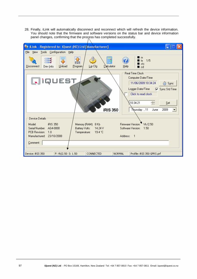
97 iQuest (NZ) Ltd - PO Box 15169, Hamilton, New Zealand Tel: +64 7 857-0810 Fax: +64 7 857-0811 Email: [email protected]
28. Finally, iLink will automatically disconnect and reconnect which will refresh the device information.
You should note that the firmware and software versions on the status bar and device information panel changes, confirming that the process has completed successfully.

iRIS Datalogger User Guide V1.50
98 iQuest (NZ) Ltd - PO Box 15169, Hamilton, New Zealand Tel: +64 7 857-0810 Fax: +64 7 857-0811 Email: [email protected]
16.4 GSM/GPRS Modem Core Firmware Upgrade Procedure ONLY APPLICABLE TO GPRS VERSIONS
NOTE: This procedure assumes familiarity with HyperTerminal®, which is the default serial terminal program that is supplied with Windows® operating systems up to XP.
1) Connect to the iRIS with HyperTerminal®. Settings should be 38,400bps, no parity, eight data bits and one stop bit. (38400 n 8 1).
2) The Main menu should appear as shown below:
* iRIS 320 GPRS (AG1-0000 / F2.30 / S1.30) 1 Site Name [My Site Name] 2 Power [Partial Save, DC] 3 Comms 4 Sensors 5 Outputs 6 Date/Time [12 Aug 2008, 08:12:48, UTC +12hrs] 7 PIN Code [0001] 8 Miscellaneous >
3) Select the Miscellaneous menu (option 8). The miscellaneous menu will appear:
* Misc Cfg 0 Exit 1 Internal Temperature [øC] 2 Initialize 3 WXT5x0 [No] 4 SDI-12 Timing [2573] >
4) Select Initialize (option 2). This prompt will appear:
> Type 'init' to initialize the unit. =
5) Enter the hidden request command “wismo” to switch the unit into native communication mode with
the GSM module. The following message will appear.
=wismo Invoking Wismo direct access mode Change terminal to 115200bps...
6) Disconnect HyperTerminal. Change the port speed to 115,200bps and disable the “Echo type
characters” option. Reconnect again.
7) Type “AT”[Enter] to confirm the link is operating to the module. An OK response should be received.
8) Type AT^IVER?[Enter] to display the core firmware version. Check the version to determine if the iRIS actually requires an update.
at^iver? iRIS GPRS Core. Version: 1.02
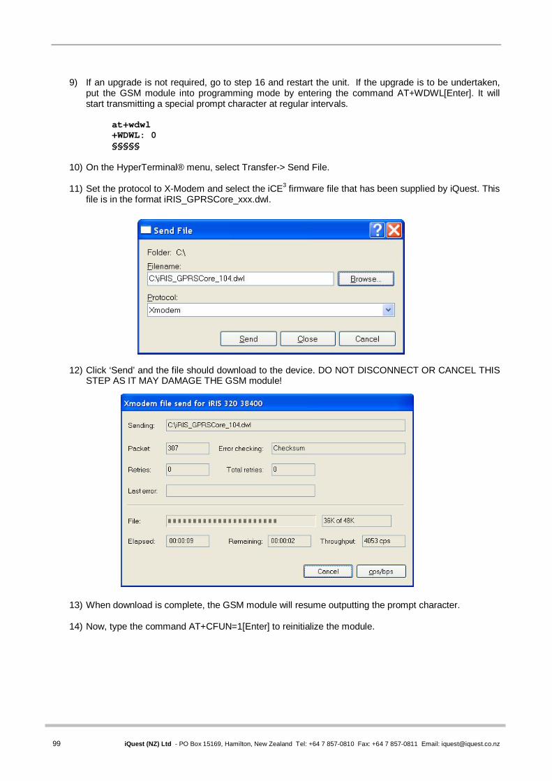
99 iQuest (NZ) Ltd - PO Box 15169, Hamilton, New Zealand Tel: +64 7 857-0810 Fax: +64 7 857-0811 Email: [email protected]
9) If an upgrade is not required, go to step 16 and restart the unit. If the upgrade is to be undertaken,
put the GSM module into programming mode by entering the command AT+WDWL[Enter]. It will start transmitting a special prompt character at regular intervals.
at+wdwl +WDWL: 0 §§§§§
10) On the HyperTerminal® menu, select Transfer-> Send File.
11) Set the protocol to X-Modem and select the iCE3 firmware file that has been supplied by iQuest. This file is in the format iRIS_GPRSCore_xxx.dwl.
12) Click ‘Send’ and the file should download to the device. DO NOT DISCONNECT OR CANCEL THIS STEP AS IT MAY DAMAGE THE GSM module!
13) When download is complete, the GSM module will resume outputting the prompt character.
14) Now, type the command AT+CFUN=1[Enter] to reinitialize the module.

iRIS Datalogger User Guide V1.50
100 iQuest (NZ) Ltd - PO Box 15169, Hamilton, New Zealand Tel: +64 7 857-0810 Fax: +64 7 857-0811 Email: [email protected]
15) When it has rebooted, recheck the version using the AT^IVER? command again.
§§§§§at+cfun=1 OK +WIND: 3 at^iver? iRIS 220/320 GPRS Core. Version: 1.04
OK
16)The GSM module core firmware upgrade is now complete. The version is showing V1.04 correctly. Restart the iRIS by either pressing the Alt key (for the iRIS 320) or by depowering and repowering (for the iRIS 220).
101 iQuest (NZ) Ltd - PO Box 15169, Hamilton, New Zealand Tel: +64 7 857-0810 Fax: +64 7 857-0811 Email: [email protected]
17 Appendix G – SDI-12
17.1 What is SDI-12? SDI-12 stands for Serial Digital Interface at 1200 bps. It is a standard to interface battery powered data recorders with microprocessor-based sensors designed for environmental data acquisition (EDA). EDA is accomplished by means of a sensor, or sensors, and a data recorder, which collects and saves the data. SDI-12 is a standard communications protocol, which provides a means to transfer measurements taken by an intelligent sensor to a data recorder. An intelligent sensor typically takes a measurement, makes computations based on the raw sensor reading, and outputs the measured data in engineering units. For example, an SDI-12 pressure sensor may take a series of pressure measurements, average them, and then output pressure in psi, inches of mercury, bars, millibars, or torrs. The sensor's microprocessor makes the computations, converts sensor readings into the appropriate units, and uses the SDI-12 protocol to transfer data to the recorder. SDI-12 is a multi-drop interface that can communicate with multi-parameter sensors. Multi-drop means that more than one SDI-12 sensor can be connected to a data recorder. The SDI-12 bus is capable of having ten sensors connected to it. Having more than ten sensors, however, is possible. Some SDI-12 users connect more than ten sensors to a single data recorder. Multi-parameter means that a single sensor may return more than one measurement. For example, some water quality sensors return temperature, conductivity, dissolved oxygen, pH, turbidity, and depth. 17.2 Advantages of SDI-12 A serial-digital interface is a logical choice for interfacing microprocessor-based sensors with a data recorder. This has advantages for sensors and data recorders.
Unique and complex self-calibration algorithms can be done in microprocessor-based sensors. Sensors can be interchanged without reprogramming the data recorder with calibration or other
information. Power is supplied to sensors through the interface. Hybrid circuit and surface mount technologies make it practical to include the power supply
regulator, a microprocessor, and other needed circuitry in small sensor packages. Sensors can use low cost EEPROMs (electrically erasable programmable read only memory) for
calibration coefficients and other information instead of internal trimming operations. The use of a standard serial interface eliminates significant complexity in the design of data
recorders. Data recorders can be designed and produced independently of future sensor development. SDI-12 data recorders interface with a variety of sensors. SDI-12 sensors interface with a variety of data recorders. Personnel trained in SDI-12 will have skills to work with a variety of SDI-12 data recorders and SDI-
12 sensors.

iRIS Datalogger User Guide V1.50
102 iQuest (NZ) Ltd - PO Box 15169, Hamilton, New Zealand Tel: +64 7 857-0810 Fax: +64 7 857-0811 Email: [email protected]
17.3 SDI-12 Electrical Interface The SDI-12 electrical interface uses the SDI-12 bus to transmit serial data between SDI-12 data recorders and sensors. The SDI-12 bus is the cable that connects multiple SDI-12 devices. This is a cable with three conductors:
1) A serial data line 2) A ground line 3) A 12-volt line
In the following specifications, all values not indicating specific limits have an allowable tolerance of ±10% of the value. The SDI-12 bus is capable of having at least 10 sensors connected to it. Serial Data Line The data line is a bi-directional, three-state, data transfer line. Table 1 shows the logic and voltage levels for the transmission of serial data for the SDI-12 standard. The data line uses negative logic.
Condition Binary state Voltage range Marking 1 -0.5 to 1.0 volts Spacing 0 3.5 to 5.5 volts Transition undefined 1.0 to 3.5 volts Table 1. Logic and voltage levels for serial data
Voltage Transitions During normal operation, the data line voltage slew rate must not be greater than 1.5 volts per microsecond. Ground Line The ground line must be connected to the circuit ground and the earth ground at the data recorder. The sensor circuit ground also must be connected to the ground line, but not normally to its own earth ground. If it is necessary to connect the sensor circuitry to earth ground, a heavy (12 AWG or larger) ground wire should be connected between the sensor earth ground and the data recorder earth ground for lightning protection. The ground conductor should be large enough to keep the voltage drop between the data recorder and all sensors less than 0.5 volts during the maximum combined sensor current drain. 12 Volt-Line The data recorder (or the external power supply) provides between 9.6 volts and 16 volts to the 12-volt line, with respect to ground, as measured under a maximum sensor load of 0.5 amperes. SDI-12 does not require the data recorder to be the source of power to the 12-volt line. Sensors connected to the 12-volt line must not have inductive loads. SDI-12 does not require voltage limiting for transient protection in the sensor. Transient protection is however recommended.
This information is taken from: SDI-12 Serial-Digital Interface Standard for Microprocessor-Based Sensors,
Version 1.3 – September 17, 2002 Prepared By SDI-12 Support Group (Technical Committee)

103 iQuest (NZ) Ltd - PO Box 15169, Hamilton, New Zealand Tel: +64 7 857-0810 Fax: +64 7 857-0811 Email: [email protected]
18 Appendix H – Internal Database Locations
WARNING: This section lists the internal database locations for the six main sensor configuration tables. This information is provided for advanced users only. Manually changing
these locations may have undesired results and should only be performed in exceptional circumstances. 1. Sensor Configuration Group Item Start Offsets 0 Source 1 Name (string) 7 Mode 8 Raw 9 fMult (float) 12 fOffset (float) 15 fEU (float) 18 fMinEU (float) 21 fMaxEU (float) 24 fCosSum (float) 27 fSinSum (float) 30 LogVal 31 LastLogDT (32 bit) 39 LoggedLastTime 40 SampleCnt 41 LogRate 42 LogMult 43 fTotEU (float) 46 Alarms (group) 80 VoiceEnable 81 SDI12Params 2. Sensor Configuration Group start addresses in database Sensor 1 d1968 Sensor 2 d2050 Sensor 3 d2132 Sensor 4 d2214 Sensor 5 d2296 Sensor 6 d2378 Sensor Multiplier, Offset and Log Multiplier addresses in memory
Sensor Multiplier (float) Offset (float) Log Multiplier (int) 1 d1977-d1979 d1980-d1982 d2010 2 d2059-d2061 d2062-d2064 d2092 3 d2141-d2143 d2144-d2146 d2174 4 d2223-d2225 d2226-d2228 d2256 5 d2305-d2307 d2308-d2310 d2338 6 d2387-d2389 d2390-d2392 d2420

iRIS Datalogger User Guide V1.50
104 iQuest (NZ) Ltd - PO Box 15169, Hamilton, New Zealand Tel: +64 7 857-0810 Fax: +64 7 857-0811 Email: [email protected]
19 Appendix I - Network Settings for iQuest APN or iQuest Global Data Network
iQuest APN (NZ only)
APN: iquest.co.nz iQuest Host IP Address: 192.168.1.10 Default Binary Port 7777 Default ASCII Port 7778 iQuest Global Data Network Network Static Host IP: 203.190.210.84 Primary Listening Ports: 7779 (UDP auto-send mode)
7780 (UDP polled mode) 7781 (TCP polled mode)

105 iQuest (NZ) Ltd - PO Box 15169, Hamilton, New Zealand Tel: +64 7 857-0810 Fax: +64 7 857-0811 Email: [email protected]
20 User Notes


