167
EDITION: 3.0 SANCTION DATE: May 2015 IRP 15: Snubbing Operations An Industry Recommended Practice (IRP) for the Canadian Oil and Gas Industry Volume 15 - 2015
| Date post: | 12-Dec-2015 |
| Category: |
Documents |
| Upload: | ricardo-yashin-tavara-la-chira |
| View: | 12 times |
| Download: | 4 times |

EDITION: 3.0 SANCTION DATE: May 2015
IRP 15: Snubbing Operations
An Industry Recommended Practice (IRP) for the Canadian Oil and Gas Industry
Volume 15 - 2015


Copyright/Right to Reproduce
Copyright for this Industry Recommended Practice is held by Enform, 2015. All rights
reserved. No part of this IRP may be reproduced, republished, redistributed, stored in a
retrieval system, or transmitted unless the user references the copyright ownership of
Enform.
Disclaimer
This IRP is a set of best practices and guidelines compiled by knowledgeable and
experienced industry and government personnel. It is intended to provide the operator
with advice regarding the specific topic. It was developed under the auspices of the
Drilling and Completions Committee (DACC).
The recommendations set out in this IRP are meant to allow flexibility and must be used
in conjunction with competent technical judgment. It remains the responsibility of the
user of this IRP to judge its suitability for a particular application.
If there is any inconsistency or conflict between any of the recommended practices
contained in this IRP and the applicable legislative requirement, the legislative
requirement shall prevail.
Every effort has been made to ensure the accuracy and reliability of the data and
recommendations contained in this IRP. However, DACC, its subcommittees, and
individual contributors make no representation, warranty, or guarantee in connection
with the publication of the contents of any IRP recommendation, and hereby disclaim
liability or responsibility for loss or damage resulting from the use of this IRP, or for any
violation of any legislative requirements.
Availability
This document, as well as future revisions and additions, is available from
Enform Canada
5055 – 11 Street NE
Calgary, AB T2E 8N4
Phone: 403.516.8000
Fax: 403.516.8166
Website: www.enform.ca

ii May 2015
Table of Contents
15.0 Preface ..................................................................................................... ix
15.0.1 Purpose ........................................................................................................ ix
15.0.2 Audience ...................................................................................................... ix
15.0.3 Scope and Limitations ................................................................................ ix
15.0.4 Revision Process ........................................................................................ ix
15.0.5 Sanction ........................................................................................................ x
15.0.6 Acknowledgements ...................................................................................... x
15.0.7 Range of Obligations .................................................................................. xi
15.0.8 Copyright Permissions ............................................................................... xi
15.0.9 Background ................................................................................................. xi
15.1 Snubbing Program ................................................................................... 1
15.1.1 Job Objectives .............................................................................................. 1
15.1.2 Well History .................................................................................................. 1
15.1.3 Risk Assessment ......................................................................................... 2
15.1.4 Emergency Response Plan (ERP) ............................................................... 3
15.1.5 Surface Equipment....................................................................................... 3
15.1.6 Down Hole Equipment ................................................................................. 4
15.1.7 Bottom hole Equipment ............................................................................... 4
15.1.8 Pre-Job Calculations .................................................................................... 7
15.1.8.1 Forces Acting on String ........................................................................ 8
15.1.8.2 Calculations Required .......................................................................... 8
15.1.9 Mitigation of Explosive Potential ................................................................ 9
15.1.9.1 Explosive Mixtures in the Casing .......................................................... 9
15.1.9.2 Explosive Mixtures in the Tubing .......................................................... 9
15.1.9.3 Surface Fires and Explosions ............................................................. 10
15.1.9.4 Other Reference Material ................................................................... 11
15.1.10 Snubbing Procedures ................................................................................ 11
15.1.11 Snubbing Vendor Selection ....................................................................... 12
15.1.12 Supervisory Control ................................................................................... 12
15.1.12.1 General Supervisory Control of Wellbore ........................................... 12
15.1.12.2 Specific Well Control Issues ............................................................... 12
15.1.12.3 Supportive Practices .......................................................................... 13

Preface IRP 15 Snubbing Operations
15.2 Down hole Equipment............................................................................ 15
15.2.1 Wireline Practices and Procedures ........................................................... 15
15.2.1.1 Wireline Practices............................................................................... 15
15.2.1.2 Wireline Plug Practices and Procedures ............................................. 15
15.2.2 Engineering Specifications ....................................................................... 18
15.2.3 Certification ................................................................................................ 18
15.3 Surface Equipment ................................................................................ 19
15.3.1 Requirements ............................................................................................. 19
15.3.1.1 Primary BOP Equipment .................................................................... 19
15.3.1.2 Auxiliary Wellhead Equipment ............................................................ 20
15.3.1.3 Snubbing Equipment .......................................................................... 20
15.3.1.4 Snubbing Unit Accumulator Requirements ......................................... 21
15.3.1.5 BOP Requirements for Rig-assisted Snubbing ................................... 22
15.3.1.6 BOP Requirements for Rigless Snubbing ........................................... 22
15.3.1.7 Lockout Equipment ............................................................................. 22
15.3.1.8 Reverse Circulation Sand Cleanout Equipment .................................. 24
15.3.2 Configuration .............................................................................................. 25
15.3.3 Engineering and Design Specifications ................................................... 26
15.3.4 Certification and Inspection ...................................................................... 27
15.3.4.1 CAODC Recommended Practices and Certifications ......................... 27
15.3.4.2 Snubbing Unit Pressure Containment Equipment ............................... 28
15.3.4.3 Hoisting Equipment ............................................................................ 29
15.3.4.4 Snubbing Unit Structure ..................................................................... 30
15.3.4.5 Wellhead and Stack Stabilization Equipment ...................................... 31
15.3.4.6 Snubbing Unit Inspections .................................................................. 31
15.4 Equipment for Rigless Operations ....................................................... 33
15.4.1.1 Cranes and Pickers ............................................................................ 33
15.4.1.2 Wellhead and Stack Stabilization ....................................................... 33
15.5 Personnel Requirements ....................................................................... 35
15.5.1 Snubbing Worker Competencies .............................................................. 35
15.5.2 Training for Multiple Contractors .............................................................. 36
15.5.2.1 Well site Supervisors .......................................................................... 36
15.5.2.2 Rig and On-site Service Personnel ..................................................... 36
15.5.3 Crew Management...................................................................................... 37

iv May 2015
15.5.4 Supervision of New Workers ..................................................................... 37
15.5.5 Crew Training ............................................................................................. 37
15.5.6 Rigless Snubbing ....................................................................................... 38
15.6 Hazard Assessments ............................................................................. 41
15.6.1 Procedures ................................................................................................. 41
15.6.2 Hazards ....................................................................................................... 41
15.7 Joint Safety Meetings ............................................................................ 45
15.7.1 Scheduling .................................................................................................. 45
15.7.2 Agenda ........................................................................................................ 45
15.7.3 Guidelines for Effective Meetings ............................................................. 46
15.8 Operational Practices and Procedures ................................................ 47
15.8.1 Well Designation Verification .................................................................... 47
15.8.2 Pre-Job Calculation Verification ............................................................... 47
15.8.3 Emergency Egress Systems ..................................................................... 48
15.8.4 Pressure Testing ........................................................................................ 48
15.8.4.1 General Pressure Testing Guidelines ................................................. 48
15.8.4.2 Preheat and Pressure Testing Guidelines for 10,000 psi BOPs .......... 49
15.8.5 Contingency Practices and Procedures ................................................... 50
15.8.5.1 Power Pack Failure ............................................................................ 50
15.8.5.2 Snubbing Unit Accumulator Failure .................................................... 50
15.8.5.3 Slip Failure ......................................................................................... 51
15.8.5.4 Annular Seal Failure ........................................................................... 52
15.8.6 Snubbing in the Dark ................................................................................. 52
15.8.7 Weather Restrictions ................................................................................. 52
15.8.7.1 Equipment Restrictions....................................................................... 52
15.8.7.2 Personnel Protection .......................................................................... 53
15.8.8 Arriving on Location and Rigging Up ....................................................... 53
15.8.9 Setting Jack Pressure ................................................................................ 54
15.8.10 Purging the Snubbing Stack ..................................................................... 55
15.8.11 Rig-Assisted Snubbing with Personnel in the Derrick or on the Tubular Racking Board ......................................................................................................... 56
15.8.12 Tripping ....................................................................................................... 56
15.8.13 Landing and Snubbing the Tubing Hanger .............................................. 58
15.8.13.1 Snubbing the Tubing Hanger with no Tailpipe .................................... 58
15.8.13.2 Snubbing in the Tubing Hanger While Pipe Light................................ 58

Preface IRP 15 Snubbing Operations
15.8.13.3 Snubbing in the Tubing Hanger with Typical PIPE HEAVY Method .... 58
15.8.13.4 Snubbing in the Tubing Hanger with the Low Pressure Method.......... 59
15.8.13.5 Snubbing in the Tubing Hanger with the High Pressure or Wellbore Full of Fluid Method ...................................................................................................... 60
15.8.14 Removing the Tubing Hanger.................................................................... 60
15.8.15 Rigging Up on a Substructure ................................................................... 62
15.8.16 Stripping Snubbing Unit On Over Existing Tubing Stump with no Tubing Hanger Landed ........................................................................................................ 63
15.8.17 Lubricating In ............................................................................................. 64
15.8.18 Lubricating Out .......................................................................................... 64
15.8.19 Picking up Tubing ...................................................................................... 65
15.8.19.1 Pipe Light ........................................................................................... 65
15.8.19.2 Pipe Heavy ......................................................................................... 65
15.8.20 Laying Down Tubing .................................................................................. 65
15.8.20.1 Pipe Light ........................................................................................... 66
15.8.20.2 Pipe Heavy ......................................................................................... 66
15.8.21 Snubbing BHA ............................................................................................ 66
15.8.22 Staging Couplings or Tool Joints ............................................................. 66
15.8.22.1 Practices for Staging Couplings or Tool Joints ................................... 66
15.8.22.2 External Upset End Tubing ................................................................. 67
15.8.22.3 Procedure for Staging Tubing Couplings in Well................................. 67
15.8.22.4 Procedure for Staging Tubing Couplings Out of Well .......................... 68
15.8.23 Reverse Circulation Sand Cleanouts ........................................................ 68
15.8.24 Securing and Un-securing the Well .......................................................... 69
15.8.24.1 Supervision ........................................................................................ 69
15.8.24.2 Situations Where Securing Is Required .............................................. 69
15.8.24.3 Overnight Shut-Ins ............................................................................. 70
15.8.24.4 Well Securement Practices ................................................................ 71
15.8.24.5 Resuming Operations After the Well Has Been Secured .................... 72
15.8.25 Laying Down Snubbing Unit ...................................................................... 72
Appendix A: Revision History.......................................................................... 75
Appendix B: Sample Job Information / Dispatch Sheet ................................ 77
Appendix C: Snubbing Services: Map 1 – Occupational Ladder and Typical Work Environments .......................................................................................... 79
Appendix D: Snubbing Unit Inspection Checklist .......................................... 81

vi May 2015
Appendix E: Semi-Annual Snubbing Equipment Inspection Checklist........ 85
Appendix F: Electrical Grounding and Bonding for Service Rigs ................ 91
Appendix G: Heat Stress Quick Card .............................................................. 97
Appendix H: Cold Weather Exposure Chart – ACGIH .................................... 99
Appendix I: Allowable Tensile Loads – Petro-Canada ................................. 101
Appendix J: Pipe Buckling Forces – Petro-Canada ..................................... 117
Appendix K: Tubing Plug and Burst Disc Recommendations .................... 137
Acronyms and Abbreviations ........................................................................ 139
Glossary .......................................................................................................... 141
References ...................................................................................................... 151

Preface IRP 15 Snubbing Operations
List of Figures
Figure 15.1.7. Typical Recommended Bottomhole Equipment Configuration 6
Figure 15.3.2. Typical Snubbing Configuration .............................................. 26
List of Tables
Table 15.0.6. Development Committee .............................................................. x
Table 15.0.7. Range of Obligation ..................................................................... xi
Table 15.0.8. Copyright Permissions ............................................................... xi
Table 15.1.12.3. Example Safety Devices ........................................................ 13
Table 15.3.4.2 Snubbing Unit Equipment Recertification Schedule ............. 29
Table 15.3.4.3. Hoisting Equipment Recertification Schedule ...................... 30
Table 15.3.4.4. Unit Structure Recertification Schedule ................................ 31
Table 15.6.2. Hazard Register .......................................................................... 42
Revision History ................................................................................................ 75


15.0 Preface
15.0.1 Purpose
The purpose of this document is to provide easily accessible snubbing operation
guidelines for all personnel involved in the development, planning and execution of the
snubbing program. IRP 15 is intended to supplement existing standards and regulations
and establish guidelines where none previously existed.
15.0.2 Audience
The intended audience of this document includes oil and gas company engineers, field
consultants, snubbing personnel, service rig personnel and regulatory bodies.
15.0.3 Scope and Limitations
This IRP includes the following pertinent information about snubbing:
Snubbing program requirements
Down hole and surface equipment specifications
Personnel requirements
Hazard assessment information
Joint safety meeting requirements
Operational procedures
IRP 15 applies to both rigless and rig-assisted snubbing operations. Most of the
information in the document pertains to both but when a recommended practice or
process is specific to one or the other the document clearly differentiates.
IRP 15 refers to other relevant standards where appropriate. A full list of the documents
referred to in this IRP and other useful reference material is provided in the References
section at the end of the document.
15.0.4 Revision Process
Industry recommended practices (IRPs) are developed by the Drilling and Completions
Committee (DACC) with the involvement of both the upstream petroleum industry and
relevant regulators. IRPs provide a unique resource outside of direct regulatory
intervention.
Technical issues brought forward to the Drilling and Completions Committee (DACC) as
well as scheduled review dates can trigger a re-evaluation and review of this IRP, in

IRP 15 Snubbing Operations Preface
x May 2015
whole or in part. For details on the specific process for the creation and revision of IRPs,
visit the Enform website at www.enform.ca.
A history of revisions to this document can be found in Appendix A: Revision History.
15.0.5 Sanction
The following organizations have sanctioned this document:
Canadian Association of Oilwell Drilling Contractors (CAODC)
Canadian Association of Petroleum Producers (CAPP)
Petroleum Services Association of Canada (PSAC)
Small Explorers & Producers Association of Canada (SEPAC)
15.0.6 Acknowledgements
The following individuals helped develop this edition of IRP 15 through a subcommittee
of DACC. We are grateful for each participant’s efforts. We also wish to acknowledge
the support of the employers of individual committee members.
Table 15.0.6. Development Committee
Name Company Organization Represented
Travis Reschny (Co-Chair) Precision Well Servicing PSAC
Don MacDermott (Co-Chair) Canadian Natural Resources Ltd. CAPP
Rick Dore Nabors Production Services CAODC
Cameron Edel High Arctic Energy Services PSAC
Rene Gendreau Powerstroke PSAC
John Hoopey Raybo Well Control PSAC
Fazal Hussain Alberta Human Services OHS Regulator – Alberta
David Papez, P. Eng Devon Canada CAPP
Budd Phillips, CRSP WorksafeBC OHS Regulator – BC
Joy Piehl WorksafeBC OHS Regulator – BC
Ray Randall Raybo Well Control PSAC
Trevor Sopracolle Goliath Snubbing Ltd. PSAC
John Taskinen, P. Tech. (Eng.) Snubco Group of Companies PSAC
Mike Watts High Arctic Energy Services PSAC
Ross Whelan Piston Well Services Inc. PSAC

15.0.7 Range of Obligations
Throughout this document the terms ‘must’, ‘shall’, ‘should’, ‘may’, and ‘can’ are used as
indicated in below:
Table 15.0.7. Range of Obligation
Term Usage
Must A specific or general regulatory and/or legal requirement that must be followed.
Shall An accepted industry practice or provision that the reader is obliged to satisfy to comply with this IRP
Should A recommendation or action that is advised
May An option or action that is permissible within the limits of the IRP
Can Possibility or capability
15.0.8 Copyright Permissions
This IRP includes documents or excerpts of documents as follows, for which permission
to reproduce has been obtained:
Table 15.0.8. Copyright Permissions
Copyrighted Information Used in Permission from
Snubbing Services: Map 1 – Occupation Ladder and Typical Work Environments
Appendix C PHRCC
Heat Stress Quick Card Appendix G OSHA
Table 1: Cooling Power of Wind on Exposed Flesh Expressed as Equivalent Temperature, 1998 Threshold Limit Values
Appendix H ACGIH
Table 2: TLVs Work Warm-Up Schedule for Four Hour Shift (Under Discretion of Supervisor on Site) – 1998 TLVs
Appendix H ACGIH
Allowable Tensile Loads Appendix I Petro-Canada
Pipe Buckling Forces Appendix J Petro-Canada
Glossary Glossary API, Schlumberger
15.0.9 Background
Snubbing is an upstream petroleum industry operation using specialized hydraulic
(snubbing) equipment and qualified personnel. Specifically, it is the act of moving
tubulars in or out of a pressurized wellbore with blowout preventers (BOPs) that are
closed and containing the pressure in the well.

IRP 15 Snubbing Operations Preface
xii May 2015
Snubbing equipment, whether rig-assist or rigless, is designed and required to perform
two functions:
1. Well control of annulus pressure. Pressure is maintained by the use of stripping blow out preventer (the configuration of which will vary by well or job requirements).
2. Movement of tubulars into and out of a well. Movement is controlled by mechanical means with enough advantage to overcome the force the well pressure exerts.
Snubbing applications include, but are not limited to, the following:
Completions
Work overs and recompletions
Stripping
Fishing and other remedial operations
Stimulation
Underbalanced drilling
The following crews or personnel may be involved during snubbing operations:
Coiled tubing crews
Down hole tool specialists
Drilling rig crews
Electric line and slick line crews
Well owner company representatives
Pumping services personnel
Safety supervisors
Service rig crews
Snubbing personnel
Well fracturing and stimulation crews
Well testing crews

Snubbing Program IRP 15 Snubbing Operations
May 2015
1
15.1 Snubbing Program
It is the primary contractor’s responsibility to prepare a written snubbing program
outlining the well site operations to be performed during snubbing. The snubbing
program may be job-specific or part of the overall well program.
IRP All snubbing operations should follow the snubbing program under the
direction of the primary contractor.
IRP The snubbing program should include the 10 components outlined below:
Job Objectives
Well History
Risk Assessment
Surface Equipment
Downhole Equipment
Pre-Job Engineering Calculations
Mitigation of Explosive Potential
Snubbing Procedures
Snubbing Vendor Selection
Supervisory Control
15.1.1 Job Objectives
Include job objectives and a brief summary of the work to be done. A checklist such as
the Sample Job Information/Dispatch Sheet provided in Appendix B can be used to
gather this information.
15.1.2 Well History
Identify any previous and potential problems that could impact the decision to include
snubbing as part of the work to be done. Summarize the history in an easy-to-use
format as background information for well site personnel.
Include, at a minimum, the following information:
Spud and rig release dates
Well location and directions to the lease
Well type (i.e., gas, oil, etc.)

IRP 15 Snubbing Operations Snubbing Program
2 May 2015
Kelly bushing (KB), cubic feet (CF) and ground level (GL) elevations
Plug back total depth (PBTD) and total depth (TD)
Sweet or sour (including H2S concentrations and release rates)
Wellhead and rig blowout preventer (BOP) data (i.e., size, type, working pressure, compressive load rating)
Casing and tubing specifications and condition
Bottom hole assembly (BHA) description and specifications
Cementing information
Stimulation information for each zone
Depths of perforations
Pressure and flow rate information for each associated formation
Reservoir temperature
Sand face and sand production
Wellhead absolute open flow (AOF)
Hydrate potential
Hydrocarbon production in a condensate type reservoir
Surface casing vent flow (if present the gas needs to be piped away from the well)
15.1.3 Risk Assessment
Review each snubbing operation to evaluate the risks and assess the need for
snubbing. Each situation has unique circumstances.
Reasons to snub include the following:
Productivity loss due to reservoir sensitivity to kill fluids.
The zone is so depleted there is not enough pressure to flow back kill fluids from the reservoir.
The zone is so permeable, fractured or over pressured that it is very difficult to keep the well killed.
Significant production loss due to the time required to kill the well or surrounding
wells.
Hazard control and mitigation processes can significantly reduce operational risks to
personnel, the environment and assets. Refer to 15.5 Hazard Assessment for
information about specific risks and safeguards. Site-specific conditions may present
additional hazards that should be considered.

Snubbing Program IRP 15 Snubbing Operations
May 2015
3
Note: For workers positioned in the derrick or on the tubing board, the
hazards or risks introduced by a live well or snubbing operation
exist in the majority of live well operations, including use of a self-
contained snubbing work over unit or underbalanced and
managed drilling operations. See IRP 22: Underbalanced and
Managed Pressure Drilling Operations Using Jointed Pipe for
more information.
New technology, approaches, procedures and engineering may be effective in reducing
the identified hazards and risks to acceptable levels. Industry is encouraged to
continuously seek risk reduction solutions to increase worker safety. Any deviations to
the risk control/mitigation safeguard considerations outlined in the Hazard Register (see
Table 15.6.2 in 15.6 Hazard Assessments) for any worker while conducting snubbing
operations requires formal written dispensation and approval by the PSAC Snubbing
Committee prior to implementation.
IRP A demonstrable, methodical and step-wise process for evaluating the
effectiveness of any new measures implemented to control/mitigate risks
to a worker positioned in the derrick or on the tubing board shall be
completed prior to industry acceptance. (i.e., An IRP 15 revision).
15.1.4 Emergency Response Plan (ERP)
The primary contractor’s generic or corporate ERP must be used along with any site-
specific plans developed in the well program. Site-specific plans should control well-
specific hazards identified during the history review (see 15.1.2 Well History), risk
assessment (see 15.1.3 Risk Assessment) or pre-job meetings.
IRP Regulatory requirements must be consulted for ERP content.
15.1.5 Surface Equipment
Review 15.3 Surface Equipment and identify the surface equipment required for the
snubbing program. Consider the following:
Well classification
Tubing and casing sizes and working pressures
Well pressure
Hydrogen sulphide content of the gas
Type of well fluids and any impact they could have on steel or elastomers
Sizes and configuration of the BHAs to be snubbed
Wellhead and rig BOP size and pressure rating
Bleed-off/flare systems
Kill systems

IRP 15 Snubbing Operations Snubbing Program
4 May 2015
Monitoring systems (e.g., ram savers or indicator lights)
Rig derrick layout and compatibility
Egress routing
Equipment spacing
General lease layout
15.1.6 Down Hole Equipment
Review 15.2 Down Hole Equipment and identify the down hole equipment required for
the snubbing program.
The two main considerations are as follows:
1. The blanking mechanism installed in the tubing string to prevent flow up the tubing during snubbing operations (see 15.2.1 Wireline Practices and Procedures).
2. The BHA to be snubbed in or out of the well as part of the tubing string.
15.1.7 Bottom hole Equipment
IRP The bottom hole equipment configuration should be compatible with the
surface equipment in terms of lengths and diameters and allow ease of
operation for staging the BHA in or out of the well.
IRP The following guidelines should be considered in the snubbing program
planning:
The BHA equipment should maintain lengths and configurations that are
“snubbing friendly.” This means:
o Tools (e.g., packers, sliding sleeves, profile nipples, jars, collars, expansion joints, etc.) are short enough that they can be easily staged through the snubbing stack and spaced out with pup joints of sufficient length to provide areas for slips and rams to close and hold on.
o Inside diameters are maintained to allow plug removal or installation.
The design should be simple to aid in release and removal of the BHA, particularly if the well is prone to issues such as sand production, scale deposition, corrosion or hydrates. Packers that are one-quarter-turn to set in compression and pick up to release are preferred.
The metallurgy, elastomers, pressure ratings and type of packing materials selected must be compatible with the well pressure, gas, fluids and pressures.
Any tubing string to be snubbed in a well shall have at least one plug seating profile in the string located at the bottom (or one pup joint up) with a pup joint installed above the profile. This connection must never be broken until pressure

Snubbing Program IRP 15 Snubbing Operations
May 2015
5
below the plug is bled off. Another pup joint (to act as a marker joint) should be placed in the string one joint above the profile nipple/pup assembly that will have the snubbing plug installed. See Figure 15.1.7 below for the typical recommended bottom hole equipment configuration.
A no-go profile should be installed below selective profiles of the same profile size.
Profiles of increasing ID shall be installed in ascending order.

IRP 15 Snubbing Operations Snubbing Program
6 May 2015
Figure 15.1.7. Typical Recommended Bottomhole Equipment
Configuration
60.3mm, 48.3mm, 6.994kg/m, J-55, T&C Upset
Tubing
Tubing Pup Joint
(acts as marker joint)
Tubing
Tubing Pup Joint
Tubing Pup Joint
60.3mm, 48.3mm, 6.99 kg/m, J-55, T&C Upset
60.3mm, 48.3mm, 6.99 kg/m, J-55, T&C Upset
60.3mm, 48.3mm, 6.99 kg/m, J-55, T&C Upset
XN No-Go Nipple
60.3 x 47.63 x 45.49, Otis, XN
Wireline Guide
60.3mm, 48.3mm,
6.99 kg/m, J-55
60.3mm, 48.3mm, 6.99 kg/m, J-55, T&C Upset

Snubbing Program IRP 15 Snubbing Operations
May 2015
7
15.1.8 Pre-Job Calculations
The pre-job calculations define safe operating parameters of the BHA, tubing, casing,
wellhead and other surface or down hole pressure containing and mass supporting
equipment. For wells with a history of corrosion, the reduced wall thickness must be
estimated or measured and reduced mechanical properties applied to snubbing
pressure and load conditions. Record the calculations in the snubbing program to
ensure all equipment selected is suitable for the service to which it will be exposed.
IRP Pre-job calculations shall be performed and documented before
commencement of snubbing operations. The calculations shall be re-
executed if well parameters or activities change significantly and those
changes were not considered in the original calculations.
IRP The following calculations and procedures shall be performed:
Snub forces must be calculated, recorded and signed off in the PSAC daily safety meeting report.
Safe stroke lengths must be calculated to prevent tubing and BHA buckling. Every snubbing jack must be able to limit the snub forces and length of stroke by a mechanical, hydraulic or computerized limiting device to work within the safe parameters of the tubing.
Maximum pulling forces and maximum allowable string weights must be determined. The true weight on the string below the pressure containing BOP is more than is indicated on the weight indicator by the hydraulic force exerted on the tubing by the well pressure (neglecting friction).
Wellbore pressures must be monitored to prevent tubing collapse, over pressuring of wellhead or stack components or reduced values for safe unsupported stroke length.
Pipe light and heavy stages must be calculated to ensure safe movement of the tubing string and the changeover point determined. Buoyancy should be considered.
BHA lengths and diameters must be measured and stripping BOP stacks appropriately assembled to ensure safe installation or recovery of tubulars, BHAs, larger OD tools, connections and tubing hangers.
Hydraulic forces acting on tubing hangers must be calculated to ensure safe securement of the well when the tubing hanger is landed (i.e. lift force acting against locking screws).
Rotary torque must be calculated for all milling, drilling or rotating operations. A mechanical, hydraulic or computerized lockout device must be installed to limit the amount of torque applied in relation to the physically achievable length of stroke of the jack. Stress on the jack cylinders must be limited to within safe working parameters.
Tubing connection torques should be established to ensure no damage is done
to the string by over torqueing.
IRP 15 Snubbing Operations Snubbing Program
8 May 2015
IRP The following personnel shall be included or carry specific responsibilities
in order to ensure the accuracy of pre-job engineering calculations:
All personnel involved in the snubbing operation should be included in a discussion of the calculation parameters at a pre-job safety meeting.
The snubbing operator should perform all calculations.
The snubbing supervisor should conduct a review of the calculations.
The well site supervisor should confirm the completion of the calculations.
IRP All pre-job calculations shall be verified on-site by the appropriate field
personnel prior to commencement of any snubbing operation.
Refer to Appendix I: Allowable Tensile Loads (Petro-Canada) and Appendix J: Pipe
Buckling Forces (Petro-Canada) for additional information.
15.1.8.1 Forces Acting on String
IRP The forces acting on a tubing or work string shall be analyzed to determine
the force needed to run the string into the well.
Generally there are five forces acting on the string:
1. Upward force created by the differential of well pressure vs. atmospheric pressure on the maximum cross-section of the tubing and tool string at the sealing surface.
2. Gravitational force (weight) of the string.
3. Frictional force for passing through BOPs.
4. Force applied by the snubbing unit (snubbing force).
5. Force from pipe drag on the casing in directional, slant or dog-legged wells.
Refer to Appendix J: Pipe Buckling Forces (Petro-Canada) for additional information.
15.1.8.2 Calculations Required
IRP The following calculations shall be performed:
Maximum snubbing force required.
Depth of neutral point.
Critical buckling load of the tubing string for the support conditions provided by the snubbing unit.
Collapse point of the tubing.

Snubbing Program IRP 15 Snubbing Operations
May 2015
9
15.1.9 Mitigation of Explosive Potential
Evaluate situations with the potential for fire or explosion and provide instructions to
eliminate or reduce the risk.
There are two primary causes of fires and explosions:
1. Practices that allow air to contacts well gas or flammable liquids at a concentration that forms an explosive wellbore mixture.
2. Situations that allow gas or flammable fluids to be bought to surface or escape to the atmosphere.
The two main areas where air can be mixed with gas at explosive concentrations during
snubbing are in the casing and in the tubing.
15.1.9.1 Explosive Mixtures in the Casing
An explosive mixture can accumulate in the casing if it is swabbed dry before it is
perforated in an underbalanced condition and the zone flows gas into the air-filled
casing. This is aggravated if the well has been shut in after perforating, which allows the
pressure to increase. Snubbing tubing into or out of this environment could detonate an
explosion.
IRP The well shall be flowed to flare at a controlled rate until the air is
displaced from the casing before the well can be shut in and the snubbing
started.
15.1.9.2 Explosive Mixtures in the Tubing
Air will usually be present in the tubing after it has been snubbed into the hole and
before the snubbing plug is pulled. Explosive mixtures can be created if well gas from
the annulus is introduced into the tubing to equalize the pressure above and below the
snubbing plug before removal.
IRP A fluid spacer shall be pumped into the tubing before the annular gas is
equalized into the tubing.
The spacer will keep the air under the fluid from contacting the gas above during wireline plug removal.
The volume required will vary with well pressure but generally one half to one cubic metre of fluid (e.g., methanol, glycol or a water mixture) will suffice.
An alternative to the spacer would be to equalize the pressure with an inert gas such as nitrogen. There may be situations where the annulus has been displaced to nitrogen. This can simplify the equalization process.
For hydrate-prone wells, a methanol spacer should be placed in the wireline lubricator before gas or nitrogen pressure is equalized into the lubricator.
IRP 15 Snubbing Operations Snubbing Program
10 May 2015
IRP Oxygen shall be purged from the lubricator with nitrogen or sweet annular
gas to prevent creation of an explosive mixture.
An oxygen monitor can be used to ensure that the sweet annular gas used for purging or pressuring is oxygen-free.
This can be done by slowly feeding the gas into the top of the lubricator through a purge sub and flowing the oxygen out the bleed-off valve at the bottom of the lubricator.
Oxygen levels must be checked at the bleed-off to determine completion of purge.
The lubricator must then be pressured to the equivalent of the wellhead pressure before an attempt is made to open the wellhead working valve or BOP
rams.
IRP The BOP stack shall be purged of any explosive gases if there are iron
sulphides present.
Iron sulphides, produced by deteriorating metal in hydrogen sulphide environments, can spontaneously ignite on contact with oxygen.
Water can be used to purge and keep tools wet.
15.1.9.3 Surface Fires and Explosions
IRP The following recommendations and guidelines for surface fires and
explosions shall be considered for the snubbing program:
Follow the plug selection and setting recommendations in 15.2 Down hole Equipment to minimize the risk of gas flowing to surface from the tubing due to snubbing plug failure.
Follow the procedures in 15.8 Operational Practices and Procedures and use all available monitoring technology to reduce the risk of tubing compression or tension failure from pulling or pushing into a closed ram or slip at surface.
The well may be displaced to nitrogen before snubbing to minimize the risk of surface fires and explosions caused by gas flows from the annulus. This will help reduce deterioration of the ram elements and seal elastomers due to prolonged exposure to well gas and fluids at elevated pressures. The nitrogen provides an inert buffer to enhance the reliability of the equipment and is non-flammable.
The tubing shall be properly purged either before or during the snubbing operation to avoid surface explosions and fires caused by gas or liquid hydrocarbons being brought to the surface inside a tubing string being snubbed out.

Snubbing Program IRP 15 Snubbing Operations
May 2015
11
Four possible options and considerations for purging procedures are listed below:
1. Swab the tubing as dry as possible and pump some fresh water down the tubing. Allow sufficient time lapse for the inversion of the water and hazardous fluids. Normally, the time to trip the tubing until reaching “wet” pipe or shutting down overnight (depending on timing) is sufficient. When wet pipe is reached swab it dry again. Use a mud can to wet trip water only that cannot be swabbed or recovered with other acceptable methods.
2. Use a pump-through type wireline plug such as an Otis TKXN, TKX, TXN, or TX to enable tubing displacement by pumping water or nitrogen. If the full displacement of the tubing is not practical, then swab the tubing as dry as possible and when reaching wet pipe at the end of the tubing string, purge with water or nitrogen.
3. Pump in a methanol cushion and equalize the shut-in casing pressure (SICP) into the tubing. Flow annulus until the shut-in tubing pressure (SITP) drops. The higher tubing pressure will be great enough to displace the liquids from the tubing through the pump-through type plug.
4. Fluid from the tubing may be displaced using coiled tubing and air or nitrogen. Air must not be used if liquid hydrocarbons are present.
15.1.9.4 Other Reference Material
The potential for explosive mixtures in the wellbore is not unique to snubbing. Other
operations such as swabbing, testing, wireline and coiled tubing may be exposed to the
same risk.
For more information refer to the following documents:
IRP 4: Well Testing and Fluid Handling includes information on air entrainment and explosive mixtures and direction on the effective use of LEL detection equipment (for detecting explosive mixtures) and also discusses purge procedures (of value when developing snubbing programs).
CAPP Flammable Environments Guideline includes information on explosive atmospheres.
AER Directive 033: Well Servicing and Completions Operations - Interim Requirement Regarding the Potential for Explosive Mixtures and Ignition in
Wells
See the References section for information about where to find these documents.
15.1.10 Snubbing Procedures
Include a written description of what operations are to be performed and what will be
accomplished with the snubbing program.
IRP Snubbing procedures should be appropriate to the task to be completed.
These procedures may be drawn from any or all of the following sources:

IRP 15 Snubbing Operations Snubbing Program
12 May 2015
15.8 Operational Practices and Procedures.
The snubbing contractor’s corporate specifications.
The primary contractor’s internal specifications.
15.1.11 Snubbing Vendor Selection
IRP A review of the following criteria shall be completed for each prospective
vendor:
Equipment Specifications
Policy and Operational Procedures
Personnel Qualifications (including training and competency certification)
Safety record
Certificate of Recognition (COR/SECOR)
WCB clearance
Regulatory compliance
Ability to provide technical and operational support
Proof of insurance
15.1.12 Supervisory Control
Clearly identify the chain of command for all snubbing operations.
15.1.12.1 General Supervisory Control of Wellbore
The well belongs to the well owner as primary contractor but there is often uncertainty
as to who takes direction from whom during snubbing operations.
IRP The primary contractor’s on-site supervisor shall maintain supervisory
control of the wellbore at all times.
15.1.12.2 Specific Well Control Issues
Moving Tubing or Tools through the BOP Stack 15.1.12.2.1
IRP Any operator needing to move the tubing string or use any wellhead or
support equipment shall communicate their intentions to all other related
service personnel to ensure all wellhead equipment is appropriately
opened or closed.
IRP The primary BOPs shall be under the direct supervision and operation of a
worker who can competently respond to a well control emergency during
any snubbing operation involving the movement of tubing or tools through

Snubbing Program IRP 15 Snubbing Operations
May 2015
13
the BOP stack. Minimum components of this competence include the
following:
The worker should be an employee of the contractor owning the primary BOP stack.
The worker must hold a valid Enform Well Service Blow Out Prevention
certificate.
Rig-Assisted Snubbing Operations 15.1.12.2.2
IRP All snubbing work to be performed shall involve both of the snubbing
operator and the service rig driller.
The snubbing operator and the service rig driller have to work closely together to
complete tasks safely and efficiently. They are both responsible for maintaining well
control and coordinating tubing string movement.
15.1.12.3 Supportive Practices
The following two practices support effective supervisory control and well control:
1. All supervisors and workers on location involved in the snubbing operation must review and agree on procedures before beginning any task. This will provide a routine for work to be done safely and efficiently. If the scope of work changes another meeting regarding the new task must be held and documented. For more information on joint safety meetings see 15.7 Joint Safety Meetings.
2. Any safety devices available to preserve the safety of on-site workers must be installed and operational and necessary personnel trained in their use. Some examples of safety devices are shown in Table 15.1.12.3.
Table 15.1.12.3. Example Safety Devices
Safety Device Purpose
Ram Indicator Systems Provide a visual aid and mechanically limit the ability to function service rig hoisting equipment while primary or secondary pipe rams are closed.
Snub and Left Force Pressure Adjustment Equipment
Mechanically limit the ability to part, bend or buckle tubing during jacking.
Crown Savers Mechanically limit the ability of the driller to strike the rig crown with the block assembly.
Escape Equipment Allows all workers on location a safe, efficient egress in case of an incident or unplanned release.
Floor Saver on Stiff Mast Snubbing Units
Mechanically prevents the travelling plate from striking the work floor.


Downhole Equipment IRP 15 Snubbing Operations
May 2015
15
15.2 Down hole Equipment
The information in this section is used to aid in the selection of down hole equipment
during snubbing program development (see 15.1.6 Down hole Equipment). It is also
used by on-site field personnel at the pre-job stage to verify the accuracy of the
equipment provided and that the equipment remains appropriate to the planned
activities.
15.2.1 Wireline Practices and Procedures
15.2.1.1 Wireline Practices
IRP The following wireline practices should be used during snubbing:
1. Run a tubing-drift gauge ring to establish tubing drift and tag the profile.
2. Run a brush through the profile if sand or scale is present to clean it before plug installation. Ensure the brush is made of a material that will not score the polished bore of the profile.
3. Set a profile-locking plug such as an Otis TKXN, TXN, TKX, TX, PXN, PX, PR, or PRN.
4. Verify the plug integrity before setting the slip stop to ensure the plug is set properly.
5. Bleed down the tubing pressure in stages to ensure plug integrity and monitor for 10 minutes per stage.
If the pressure does not bleed off then pull the assembly and assess the problem.
Corrective action may include one of the following:
Re-brush or re-clean the profile and rerun
Try another profile
Install a non-profile plug such as a permanent bridge plug
15.2.1.2 Wireline Plug Practices and Procedures
IRP Hook-wall plugs, G pack-offs and similar plugs shall only be used for
snubbing on wells and conditions where they can be used with a surface
valve.
IRP The following wireline plug practices and procedures shall be used during
snubbing:

IRP 15 Snubbing Operations Downhole Equipment
16 May 2015
All wire line plugs and tools shall be installed and removed by qualified wire line personnel in the manner identified in the snubbing program.
Plugs installed in profiles at surface shall be pressure tested from below to 1.3 times the bottom hole pressure. The pressure test shall be documented on the
daily tour sheet.
Profile plugs 15.2.1.2.1
Care shall be taken to correctly match the plug specified to the profiles installed in the tubing string.
A permanent tubing bridge plug should be set if the profiles no longer work or are not there.
Any leaking plug shall be removed before a bridge plug is set.
The condition of the tubing ID will affect the seal of the bridge plug element when it is set. Install a second plug if seal effectiveness is in doubt.
Acceptable single barriers used with slip stops are wireline set selective plugs (e.g., an Otis-style TKX, TX, PX or PR) or a no-go locking plug (e.g., an Otis TKXN, TXN, PXN, or PRN, interference-style locks).
A down hole shut-off valve, permanent bridge plug or tubing end plug can be
used without a slip stop. Additional guidelines are as follows:
o If the plug has an equalizing prong, the prong should be a locking style or be pinned in place.
o Use of a pump-through type wire line plug such as an Otis TKXN, TKX, TXN, or TX enables tubing displacement by pumping water or nitrogen. It can also utilize wellbore gas and differential pressure between tubing and casing
pressure by equalizing tubing and then flowing the casing.
A fluid column in the tubing may be used to reduce the effects of increased differential pressure across a single plug. Avoid the use of highly flammable or
hydrocarbon based fluids.
Non-Profile plugs 15.2.1.2.2
Tubing end plugs are suitable for snubbing in final tubing installations.
Down hole shut-off valves are suitable when the tubing is to be round-tripped.
Tubing end plugs are an acceptable alternative when dual barriers are required and are recommended for final tubing string installations where there is no
equipment below the tubing end.
Slip Stops 15.2.1.2.3
IRP The following slip stop practices and procedures should be used during
snubbing:

Downhole Equipment IRP 15 Snubbing Operations
May 2015
17
A slip stop shall be installed immediately above the fish-neck of the equalizing prong as a second measure to prevent upward movement and subsequent dislodging.
The slip stop shall be set immediately above injection or pump-through style plugs (e.g., TKXN, TKX, TXN or TX) to help hold them in place.
The ID of the slip carrier for Otis-style plugs shall be restricted enough to prevent the fish-neck of the prong from entering and tagging the slip stop body (which could cause a release of the slip stop).
The slip stop for Baker-style plugs shall have an extension fastened to the bottom of the body that is of sufficient ID and length to pass over the fish-neck of the plug and exert downward force to the lock mandrel. Downward force
applied to the fish-neck of a Baker-style plug may cause a release.
Dual Barriers 15.2.1.2.4
IRP The following dual barrier practices and procedures should be used during
snubbing:
High pressure gas may be trapped between the plugs when dual barriers have been installed. Use caution and care to ensure that the pressure is relieved between the barriers.
For snubbing out, the lower plug installed should be an injection or pump-through style and the upper plug should be a blanking style. This will allow the pressure to bleed continuously through the plug into the wellbore as the tubing is withdrawn from the well.
The lower plug should be negative pressure tested after installation by bleeding off the tubing pressure.
The upper plug’s pressure integrity should be determined by filling the tubing with fluid, pressure testing and swabbing the tubing dry after. Nitrogen can be used if the tubing cannot be easily swabbed or hydrates are a concern.
Reverse the order of the plugs described above when snubbing in.
Note: A slip stop is not considered a barrier.
Down hole ¼ Turn Valves 15.2.1.2.5
IRP The following down hole ¼ turn valve practices and procedures should be
used during snubbing:
Down hole shut-off valves may be used if rotating the tubing to manipulate the valve can be performed effectively.
The down hole ¼ turn valve shall be pressure tested and charted equal to the requirements for a plug set in a profile at the surface after being serviced and
before each use.

IRP 15 Snubbing Operations Downhole Equipment
18 May 2015
15.2.2 Engineering Specifications
Wireline companies and well owners have several down hole equipment supply options.
Down hole equipment performance is influenced by quality control during manufacturing
and the condition of the equipment at the time of plug installation. The failure of a plug
to hold pressure could be related to the plug being manufactured or repaired to a
condition that is “out of spec” or set in a profile that is out of spec. It is as important to
ensure that the down hole equipment being installed is within manufacturer tolerances
as it is to install the equipment properly.
15.2.3 Certification
IRP All down hole equipment (e.g., tubing plugs and profiles) shall be certified
by the original equipment manufacturer (OEM) as being suitable for the
environment that the equipment will be exposed to (e.g., pressure rating,
wellbore fluids, etc.).
Equipment not from an OEM may be substituted if it is accompanied by a letter of
conformance or compliance or is approved by a certifying professional engineer as
being suitable for the application.
The certifying professional engineer shall have the following credentials:
Previous experience or training with pressure control equipment.
Practical working knowledge of down hole completion equipment.
Experience with general quality control standards.
Professional engineering status in the jurisdiction of practice.
The end user is responsible for selecting appropriate materials for the well environment
or accepting manufacturer recommendations. It is the responsibility of the well owner to
ensure the materials comply with the requirements and are certified by the
manufacturer.

Surface Equipment IRP 15 Snubbing Operations
May 2015
19
15.3 Surface Equipment
The information in this section is used to aid in the selection of surface equipment
during snubbing program development (see 15.1.5 Surface Equipment). It is also used
by on-site field personnel at the pre-job stage to verify the accuracy of the equipment
provided and that the equipment remains appropriate to the planned activities.
Surface equipment specifications refer to the following:
All wellbore pressure-containing components of the snubbing unit.
All BOPs, bleed-offs, equalizing spools, spacer spools, plug valves and equalizing lines.
Hydraulic systems incorporated to facilitate pipe-tripping operations.
Lifting and rigging systems for rigless snubbing operations.
The design requirements for functioning the well containment systems on the
snubbing unit.
15.3.1 Requirements
15.3.1.1 Primary BOP Equipment
The primary BOP equipment is operated by the snubbing unit operators in rigless
operations and by the service rig crew in rig-assist operations.
IRP Regulatory requirements of the applicable jurisdiction must be followed for
all primary BOP equipment.
IRP If a well has H2S of 1% or more or BHP of 21,000 KPA or more, one of the
following well control methods should be applied:
1. Install a shear ram as the lowermost primary BOP.
2. Connect a pump and tank to the wellbore and keep a minimum of one hole volume of fluid on site.
The use of substances that are incompatible with certain polymers (e.g., aromatic
fracturing oil, methanol and CO2) will contribute to annular seal failures and potentially
compromise equipment performance. This can be mitigated by limiting the use of
primary annular preventers previously exposed to such substances. Having a surface
blanket of fluid or inert gas will also mitigate the chance of exposure. Once exposed, the
annular seals and element should undergo a visual inspection and pressure test before
being returned to use.
IRP Primary BOP controls must be readily accessible.

IRP 15 Snubbing Operations Surface Equipment
20 May 2015
Employers shall perform a risk assessment to determine the optimal placement of BOP controls for their specific operations.
All primary well control BOPs must be connected to an accumulator that meets the requirements of the regulations of the applicable jurisdiction and shall be isolated from the snubbing accumulator system.
For primary BOP applications refer to Schedule 10 of AER Directive 37: Service Rig Inspection Manual (Alberta) and/or section 8.144 of the Oil and Gas
Conservation Regulations (Saskatchewan).
15.3.1.2 Auxiliary Wellhead Equipment
A full-opening valve may be installed below the primary BOPs as a safe alternative to
snubbing in a tubing hanger in the following situations:
When well owner policy dictates that the tubing hanger be landed for dual barrier securement overnight.
For rigless operations.
When there is no tubing.
When multiple tubing sizes necessitate ram changes and pressure testing of the BOP equipment.
For well conditions with high pressure aromatic-rich gas that can cause premature elastomer failure.
For well conditions with highly sour and/or corrosive well fluids that can cause
premature metal failure.
15.3.1.3 Snubbing Equipment
Rig-Assist and Rigless Snubbing Equipment 15.3.1.3.1
For the purposes of this IRP, a rig assist or rigless snubbing unit is defined as having
the following components:
Two BOPs, usually one stripping ram and one annular. An extra stripping ram is used on wells with a surface pressure higher than 21mPa and rigless snubbing units will also include primary BOP equipment.
One or more working spools with ports for bleeding off and equalizing wellbore pressure between BOPs.
A slip assembly made up of one or two sets of snubbing slips (to control upward movement of the tubing string) and one or two conventional (heavy) slips (to aid in transition to and in pipe heavy stripping).
A mechanical system to move tubulars or pipe in or out of a well (e.g., cable, cylinders and rack-and-pinion systems)
A power pack that supplies power to the hydraulic system. On mobile units the truck motor may supply power to the hydraulic system when the truck is
stationary.

Surface Equipment IRP 15 Snubbing Operations
May 2015
21
The following requirements apply to surface snubbing equipment:
The snubbing unit shall be able to control tubulars at wellbore pressure.
Surface pressure should be reduced if greater than the working pressure of the snubbing stack. Surface pressure and stress on the snubbing stack can be reduced using control measures such as a column of fluid or flowing the well.
The mechanical system shall be strong enough to overcome the maximum hydraulic lift force on tools and tubing at surface (see 15.1.8 Pre-Job Calculations for information regarding pressure-area calculations).
The maximum surface pressure shall be used for pressure-area calculations.
All components of the snubbing unit hydraulic system (i.e., hoses, fittings, directional valves, piping) shall have a working pressure rating equal to or greater than the working pressure rating of the hydraulic system.
The hydraulic tank design shall include sufficient venting to allow escape of gas in the event of a BOP wellbore seal failure.
The accumulator and jack circuits shall not use silver solder fittings.
The snubbing unit shall have gauges, labeled and visible from the operator’s
position, which accurately indicate the following:
o Wellbore pressure
o Push/pull force
o Accumulator pressures
o Operating pressure
o Annular closing pressure
o Slip pressure
The panel in the snubbing basket shall house all the manually operated controls for the slips, BOPs and jack and there must be a lockout system for these controls (see 15.3.1.7 Lockout Equipment).
The snubbing unit may use a proven technology (e.g., interlock systems) to ensure one set of the appropriate slips is closed at all times during snubbing operations. If this technology is used there shall be written procedures, training and demonstrated competency in its use.
The rig assist snubbing unit shall include a system to prevent the snubbing operator from accidentally closing a snubbing slip while the service rig is tripping
out of the hole.
15.3.1.4 Snubbing Unit Accumulator Requirements
The snubbing unit accumulator requirements are as follows:
The design shall include a usable fluid volume that, with the annular preventer closed, allows two functions of a single gate preventer and two functions of the

IRP 15 Snubbing Operations Surface Equipment
22 May 2015
actuators for the bleed-off/equalizing plug valves. A minimum pressure of 8,400 KPA shall be maintained on the snubbing unit accumulator circuit after performing these functions.
The snubbing unit accumulator shall be able to maintain closure of the annular preventer for a minimum of ten minutes while maintaining a minimum of 8,400
KPA with no power to the recharge pump.
Note: 8,400 KPA remaining on the accumulator system may not be
sufficient to close specific types of 10,000 psi BOPs. The OEM
manual for the BOP should be consulted to confirm that the
accumulator has sufficient closing volume for the BOP it is
matched with.
The snubbing unit accumulator shall have a low-pressure warning system.
15.3.1.5 BOP Requirements for Rig-assisted Snubbing
The BOP Requirements for rig-assisted snubbing are as follows:
Primary BOPs should be equipped with ram-savers that prevent the movement of pipe when a ram BOP is closed.
The BOP ram shall be equipped with either ram-indicators or ram-savers to prevent or restrict the movement of pipe by the service rig when the snubbing ram is closed.
A ram-saver device that limits the ability of the service rig to pull pipe when a BOP ram is closed should be seriously considered.
A visual indicator that clearly indicates the position of the BOP ram(s) to the
snubbing operator and driller shall be used if a ram-saver device is not used.
Note: It is critical that the ram-savers or the indicator system be fully
functional before commencing tripping operations (see 15.8.12
Tripping).
15.3.1.6 BOP Requirements for Rigless Snubbing
The BOP Requirements for rigless snubbing are as follows:
Primary BOPs shall be equipped with either ram indicators that alert the operator to the position of the primary rams or ram-savers that prevent the movement of pipe when the ram is closed.
The BOP ram shall be equipped with ram indicators that clearly indicate the
position of the BOP ram(s) to the snubbing operator.
Note: It is critical that the ram-savers or the indicator system be fully
functional before commencing tripping operations (see 15.8.12
Tripping).
15.3.1.7 Lockout Equipment

Surface Equipment IRP 15 Snubbing Operations
May 2015
23
IRP A lockout system shall be in place to prevent equipment from becoming
energized if there is potential for workers to be injured while they are
inside the range of motion of that equipment.
IRP Snubbing service providers shall have lockout procedures on site for
workers to follow.
IRP Snubbing unit components that shall have lockouts include, but are not
limited to, the following:
Power Tongs
Slip Controls
Snubbing BOP Controls
Jack Control
Annular
Power Tongs 15.3.1.7.1
The requirements and procedures to lockout power tongs are as follows:
Open faced tongs shall be fitted with a gate to be closed during operation
All tongs shall have means to eliminate hydraulic flow through the tong motor when lockout is needed.
The lockout device shall be used during die changes and other maintenance or
repair.
Slip Controls 15.3.1.7.2
The slip control panel lockout should be used when:
The snubbing operator leaves the basket.
Other service contractors are in the basket and the tubing string will not be moving.
Maintenance is being performed where workers could be injured if the slips are
inadvertently activated.
Snubbing BOP Controls 15.3.1.7.3
The snubbing BOP panel lockout should be used when:
The operator leaves the basket.
Other service contractors are in the basket and the tubing string will not be moving.
Maintenance is being performed where workers could be injured.

IRP 15 Snubbing Operations Surface Equipment
24 May 2015
Jack Control 15.3.1.7.4
Jack control shall include a mechanical or hydraulic lockout device to prevent
inadvertent movement of the jack plate while workers are on or under the jack plate.
Annular 15.3.1.7.5
A lockout shall be in place to prevent the annular control from being opened
unintentionally or by mistake. This lockout must provide a step before the control can be
opened.
15.3.1.8 Reverse Circulation Sand Cleanout Equipment
Typical sand cleanout equipment consists of the following:
A 15 m by 50 mm double or triple-braided hose
An emergency shutdown (ESD) valve
Several slim hole valves
A tubing swivel
A Chiksan or heavy-walled elbow
IRP All surface sand cleanout equipment shall have a working pressure equal
to or greater than the bottom hole pressure.
The reverse circulation sand cleanout equipment requirements are as follows:
Flow back lines from the tubing and the snubbing unit bleed off line shall be connected in such a way that if the upper snubbing BOP needs to be opened at any time, the snubbing stack can be bled off to zero beforehand.
o Sources of pressure include back pressure from the test vessel or line pressure from the flowing tubing.
o The lines shall terminate according to well owner policy or applicable jurisdictional regulation.
All the surface equipment used for sand cleanouts shall be dedicated solely for that purpose and shall be in addition to normal rig inventory.
The valves shall be lubricated and pressure tested after each use.
Valves shall be sent for repair and recertification to OEM specifications when leaks are detected.
The equipment owner should maintain a logbook to help predict when repair or replacement of valves will be needed. The log book entries should include the
following:
o Serial number for each valve
o Date of use

Surface Equipment IRP 15 Snubbing Operations
May 2015
25
o Volume of sand flowed through the valve body
o The working pressure the valve was exposed to
Hose ends shall be equipped with integral crimped ends.
Hoses will typically bubble before failing and shall be replaced, not repaired, when this occurs.
The swivel and Chiksan should be inspected for erosion wear after each use and repaired as needed.
All components of the sand cleanout system shall be hydraulically pressure tested to at least 10% above the maximum anticipated operating pressure (but not above the working pressure) before use.
For reverse sand cleanouts, a remote-activated fail-close shut-off shall be installed on a valve upstream of all flow back equipment at the top of the tubing string. This device shall be function tested before use.
15.3.2 Configuration
The following are general guidelines and recommendations for the configuration of
surface equipment:
All snubbing units shall be equipped with engineered fall protection and arrest devices as per applicable occupational health and safety regulations. Risk assessment, training and procedures are required for the use of egress systems.
Careful consideration is needed when assemblies are being designed for snubbing operations. If there are odd-shaped items to be run or pulled, a spool shall be placed in the snubbing BOP assembly with sufficient length to cover the item. This spool then becomes a lubricator.
All components exposed to the wellbore environment in sour wells must meet NACE standards.
Double valves shall be used on critical sour wells for the snubbing unit and the bleed-off and equalize loops.
On any well deemed critical sour or high risk, shear rams with sufficient accumulator and nitrogen back-up shall be installed in the lowest ram in the primary BOP stack. For more information see IRP 2: Completing and Servicing Critical Sour Wells.
Diesel engines equipped with exhaust regeneration can create exhaust temperatures in excess of 1000° F. Consider securing the well when engines within 25 m (75 ft.) are regenerating. Refer to IRP 20 Well site Design Spacing Recommendations and AER Directive 37: Service Rig Inspection Manual
Section 250 for more information about equipment spacing.
Although each well and snubbing operation will be unique, Figure 15.3.2 depicts a
typical configuration for a snubbing unit with the components labeled for reference.

IRP 15 Snubbing Operations Surface Equipment
26 May 2015
Figure 15.3.2. Typical Snubbing Configuration
15.3.3 Engineering and Design Specifications
All snubbing equipment in use must be certified by a certified professional engineer
using the appropriate and applicable standards from the following:
American National Standards Institute (ANSI)
American Petroleum Institute (API)

Surface Equipment IRP 15 Snubbing Operations
May 2015
27
American Society of Mechanical Engineers (ASME)
Canadian Standards Association (CSA)
National Association of Corrosion Engineers (NACE) if the equipment will be exposed to H2S
The certifying professional engineer will have the following:
Previous experience or training with pressure control equipment
Practical working knowledge of surface equipment
Experience with general quality control standards
Professional engineering status in the jurisdiction of practice
15.3.4 Certification and Inspection
Certificates are part of due diligence and help field personnel know the type and
condition of the equipment they are using. A document with an engineer’s stamp
constitutes certification for equipment. A copy of the certificates shall be on site and up
to date.
15.3.4.1 CAODC Recommended Practices and Certifications
IRP The equipment identified in the following CAODC recommended practices
shall have certifications:
RP 3.0 – Service Rigs Inspection and Certification of Masts
RP 3.0A – Service Rigs Inspection and Certification of Substructures, Draw works and Carriers
RP 4.0 – Service Rigs Overhead Equipment Inspection and Certification
RP 6.0 – Drilling Blowout Preventer Inspection and Certification
RP 7.0 – Service Rigs Well Servicing Blowout Preventer Inspection and
Certification
Specific components include, but are not limited to, the following:
Pipe rams
Annulars
Slip bowls
Jack structure
Overhead equipment including:
o Pick-up elevators
o Short bails

IRP 15 Snubbing Operations Surface Equipment
28 May 2015
o Overhead Slings
o Pick-up nubbins
o Spreader bars
o Winch line weights (if equipped)
Equalize lines
Chokes
Pancake flanges
Hoses and piping
Equalize hoses (if equipped)
Fall arrest equipment (covered in OH&S, not RP's)
Ram blocks
Accumulator bottles
Tubing winches (if equipped)
Spool lifting brackets (if equipped)
Spools (including the working spool between BOPs)
The certification schedules in the CAODC RPs and detailed below are the minimum
required intervals for recertification of surface equipment and should be done more
frequently if recommended by the OEM. All equipment must be maintained to
manufacturer specifications.
AER Directive 037: Service Rig Inspection Manual outlines procedures and items
checked by AER staff when inspecting service rigs in Alberta.
15.3.4.2 Snubbing Unit Pressure Containment Equipment
All wellbore pressure containing equipment must be hydrostatically tested to the
maximum working pressure of the components every three years. Documentation must
be kept with the unit and at the base of operations.
IRP Snubbing unit equipment certification shall include, but is not limited to,
the equipment and recertification intervals in Table 15.3.4.2 Snubbing Unit
Equipment Recertification Schedule.

Surface Equipment IRP 15 Snubbing Operations
May 2015
29
Table 15.3.4.2 Snubbing Unit Equipment Recertification Schedule
Equipment Recertification
Interval
Equalize line (steel or hose) 1 Year
Calibration Interval for Critical Gauges 3 Years
Load cells 1 Year
Annular 3 Years
Bleed-off valves 3 Years
Equalize valves 3 Years
Load plate 3 Years
Ram blocks 3 Years
Rams 3 Years
Spacer spools 3 Years
Stripping heads 3 Years
T-block and/or flow cross 3 Years
Tubing safety valves 3 Years
Work spool 3 Years
15.3.4.3 Hoisting Equipment
IRP Hoisting equipment certifications shall include, but are not limited to, the
following:
All components of the hoisting equipment must have an engineered rating sufficient for the lift.
All welded components of the hoisting equipment must have an engineered rating and be non-destructive (ND) tested at the time of manufacture and at six-year intervals thereafter.
Wire rope equipment must follow all wire rope manufacturer rejection criteria.
Tubing transfer elevators must have an engineered rating, be certified every three years and incorporate a double latch or secondary safety lock to prevent inadvertent opening.
IRP Hoisting equipment certification must include, but is not limited to, the
equipment and recertification intervals in Table 15.3.4.3 Hoisting
Equipment Recertification Schedule.

IRP 15 Snubbing Operations Surface Equipment
30 May 2015
Table 15.3.4.3. Hoisting Equipment Recertification Schedule
Equipment Recertification
Interval
Slings 1 Year
Pick-up elevators 3 Years
Shackles 3 Years
Sheaves 3 Years
Elevator links 6 Years
Pick-up subs 6 Years
Rack and pinion 6 Years
Spreader bar 6 Years
Stand-up hoists 6 Years
Tong raising ram assembly 6 Years
15.3.4.4 Snubbing Unit Structure
IRP All snubbing equipment structural components shall be inspected every
24,000 hours of operation. All equipment shall have a log book of
accumulated operating hours since the last Level IV Inspection. If this log
book does not exist inspection frequency shall be every six calendar
years.
Unit structure certification requirements include, but are not limited to, the following:
The unit structure must have an engineered rating and all welds of load-bearing components must have an engineered weld procedure.
All load-bearing components of the unit shall be ND tested according to the inspection schedule.
Snubbing jack certification shall include maximum push/pull ratings and be clearly visible on the jack itself (such as a rating plate or label affixed to the
unit).
Unit structure certification shall include, but is not limited to, the equipment and
recertification intervals in the following table:

Surface Equipment IRP 15 Snubbing Operations
May 2015
31
Table 15.3.4.4. Unit Structure Recertification Schedule
Equipment Recertification
Interval
Fall arrest support 6 Years
Jack cylinder 6 Years
Load plate (not part of BOP system) 6 Years
Rotary bearing assembly 6 Years
Slip bowls 6 Years
Slip windows 6 Years
Support legs and/or angle iron 6 Years
Traveling plate 6 Years
Window plate 6 Years
Load bolts and nuts as per engineered requirement
15.3.4.5 Wellhead and Stack Stabilization Equipment
IRP Certification requirements for wellhead and stack stabilization equipment
shall be as follows:
The certification for all stabilization systems must be specified by the design engineer and followed by the snubbing company.
The recertification interval is a maximum of three years if the system contains wellbore pressure.
The Recertification interval is a maximum of six years if the system does not
contain wellbore pressure.
15.3.4.6 Snubbing Unit Inspections
IRP Snubbing unit inspections must be completed after each rig-up and every
seven days of operation or weekly after initial rig-up.
Refer to the Snubbing Unit Inspection checklist in Appendix D.


Equipment for Rigless Operations IRP 15 Snubbing Operations
May 2015
33
15.4 Equipment for Rigless Operations
The nature of rigless snubbing operations means that there are some equipment
requirements that are specific to rigless operations.
15.4.1.1 Cranes and Pickers
The majority of rigless snubbing operations involve a picker or a crane to position
snubbing equipment on the well (rigging up).
IRP Lifting and hoisting regulations must be considered for each province of
operation.
15.4.1.2 Wellhead and Stack Stabilization
IRP All wellhead/snubbing BOP stack stabilization systems must be
engineered with the following minimum parameters:
Maximum load rating
Maximum wind speed loading to ensure stability
Maximum BOP/snubbing stack heights
These parameters must be available on site as documentation or a manufacturer data
plate must be mounted on the structure.
Operating procedures shall be available and followed to ensure stabilization is
maintained equally on all components of the system.


Personnel Requirements IRP 15 Snubbing Operations
May 2015
35
15.5 Personnel Requirements
15.5.1 Snubbing Worker Competencies
IRP Snubbing personnel should be certified under the Petroleum Competency
Program (PCP) Standards of Competence for Snubbing Services.
These standards were revised effective January 1, 2006. During their implementation
period, snubbing companies will begin implementing these revised standards, and oil
and gas companies are advised to use personnel certified under these standards to
ensure competent snubbing personnel.
Definitions related to the PCP program are listed below:
Petroleum Competency Program: The Petroleum Human Resources Council of Canada (PHRCC) developed the PCP. This program identifies standards of competence for specific petroleum-related occupations and supports assessment of those standards. For further information see the PSAC website (Occupational Competencies – PCP Program), as well as Alberta Apprenticeship and Industry Training summary and related regulation.
Standard of Competence: A standard of competence is a written specification of the knowledge and skills required by a worker to be applied over the range of circumstances demanded by a job.
Snubbing Services Career Ladder and Standards of Competence: The snubbing industry has identified a ladder of six occupations for snubbing
services within the context of the PCP:
1. Assistant Operator 2. Snubbing Operator Level 1 3. Snubbing Operator Level 2 4. Snubbing Operator Level 3 5. Snubbing Supervisor Level 1 6. Snubbing Supervisor Level 2
Note: The snubbing industry has identified the standards of competence
for each occupation identified above.
Note: Refer to Appendix C for a chart illustrating this career ladder.
Worker Competencies: The occupation ladder and standards of competence for the snubbing services sector provide a framework for assessing and certifying a worker’s competence. In addition to these defined standards, companies will most likely have their own performance criteria and qualifications based on their particular corporate culture and strategic objectives. Companies may use different equipment and operating procedures so workers are certified in that context.

IRP 15 Snubbing Operations Personnel Requirements
36 May 2015
Assessment and Certification: Individuals are certified competent in an occupation when they fulfill the requirements of the Standards of Competence for Snubbing Services combined with the ability and desire to apply those skills at an acceptable level of performance over the range of circumstances demanded by each job. Worker competence is assessed by snubbing assessors trained through the PCP. Snubbing assessors evaluate competence using a systematic approach for determining the skill levels of employees. A certificate of competence is issued only when there is clear evidence that a
worker meets the Standard of Competence.
15.5.2 Training for Multiple Contractors
Snubbing operations involve non-snubbing personnel. Training requirements for non-
snubbing personnel are listed below. These training requirements are in addition to
applicable jurisdictional legislation and regulations.
15.5.2.1 Well site Supervisors
IRP The well site supervisor should have a clear understanding of the
following:
Snubbing calculations
Snubbing procedures
Equipment and personnel requirements
Industry Recommended Practices including compliance with IRP 7: Standards for Well site Supervision of Drilling, Completions and Work overs
Hazards specific to snubbing
IRP The well site supervisor should have thorough knowledge of the snubbing
program and ensure all services coming on site have the required training
for the equipment.
15.5.2.2 Rig and On-site Service Personnel
IRP Rig personnel and all other on-site service personnel should be trained in
all applicable IRPs and industry standards and be made aware of the
following:
Hazards specific to snubbing
Job scope
Snubbing procedures
IRP Rig and other on-site service personnel shall be involved in development
of the ERP and be aware of their roles in it.

Personnel Requirements IRP 15 Snubbing Operations
May 2015
37
15.5.3 Crew Management
Job scope will dictate the number and type of snubbing personnel required on location.
Personnel requirements are at the discretion of the snubbing contractor.
IRP The snubbing supervisor is responsible for crew fatigue management and
shall ensure work shifts are either:
1. scheduled within the parameters of applicable legislation or
2. scheduled such that a shift does not extend to more than 15 hours (including crew travel) with an 8-hour rest period between shifts
whichever is less.
15.5.4 Supervision of New Workers
IRP Employees with little or no snubbing experience shall be closely
supervised during all work activities.
IRP Any new workers on site shall be identified in the pre-job safety meeting
and any expectations of those workers shall be outlined to all other
workers on location.
IRP Supervision shall be present and instructive until workers understand and
can use all information presented to them (as outlined in the common core
and assistant operator occupations in the PCP Standards of Competence
for Snubbing Services. See 15.1.1 Snubbing Worker Competencies above).
15.5.5 Crew Training
Additional general crew training requirements are as follows.
IRP All crew members required by jurisdiction or site owner policy to use fall
protection equipment (e.g., harnesses, lifelines or lanyards) must possess
fall protection certification.
IRP If a boiler that requires a certified operator is in operation, at least one
person on site must possess a Special Oilfield Boiler Certificate.
Other training available for the enhancement of crew competency includes the following:
First Line Supervisor’s Blowout Prevention
Safety and Regulatory Awareness
Fire extinguisher use and maintenance
Basic firefighting

IRP 15 Snubbing Operations Personnel Requirements
38 May 2015
Fluid handling/pumping duties (from CAODC Derrickhand Competency)
Training to address AER Directive 33: Well Servicing and Completions Operations – Interim Requirement Regarding the Potential for Explosive Mixtures and Ignition in Wells
15.5.6 Rigless Snubbing
The crew requirements specific to rigless snubbing are as follows.
IRP All members of a rigless crew shall have the following minimum training
and certifications:
H2S Alive
WHMIS
Applicable Industry, Company and Site Orientations (e.g., PSCD, eGSO, online requirements)
IRP All drivers of mobile rigless equipment shall have the following minimum
training and certifications:
Appropriate operator’s license with air endorsement where required
Transportation of Dangerous Goods (TDG) training
Note: Additional training such as General Oilfield Driver Improvement
(GODI), Heavy Hauler, Hours of Service, Fatigue Management
and Cargo Securement are available and may be required for
drivers based on jurisdiction or operating status.
IRP The operator of a snubbing unit in a rigless application shall be competent
in accordance with the PHRCC Occupational Ladder or equivalent. In
addition the operator shall possess the following minimum training and
certifications:
Blowout Prevention – Well Servicing
Fall Protection for Rig Work
Standard First Aid
IRP The operator of a crane or well head boom truck shall meet the training
requirements of the jurisdiction.

Personnel Requirements IRP 15 Snubbing Operations
May 2015
39
IRP The supervisor of a rigless snubbing operation shall be competent in
accordance with the PHRCC Occupational Ladder or equivalent. In addition
the supervisor shall possess the following minimum training and
certifications:
Blowout Prevention – Well Servicing
Fall Protection for Rig Work
Standard First Aid
IRP At least one crew member of a rigless operation shall possess the
following training and certifications or equivalent:
Detection and Control of Flammable Substances
Fall Rescue for Rig Work
IRP All crane or picker operators must hold a certification either as an
apprentice/journeyman Wellhead Boom Truck operator or NCCCO Crane
Operator.
Review the Enform Derrickhand Competency guide for pumping and fluid handling
requirements.


Hazard Assessments IRP 15 Snubbing Operations
May 2015
41
15.6 Hazard Assessments
Snubbing contractors shall refer to the following resources for hazard assessment:
The hazard information in 15.6.2 Hazards below.
Task Analyses or Job Procedures (JSAs)
PSAC Snubbing Pre-Job Safety Meeting Report and Snubbing Hazard
Assessment
15.6.1 Procedures
IRP The snubbing contractor shall take the following actions during hazard
assessment:
Discuss the job scope with all on-site personnel
Identify hazards
Assign risk factors to each hazard
Discuss hazard control measures with on-site personnel
IRP For any deviation from the job scope the snubbing contractor shall take
the following actions:
Stop all operations
Complete a new hazard assessment
Re-evaluate personnel requirements
IRP The well site supervisor must ensure that all the personnel on location
participate in, and document their involvement in, the hazard assessment
(as applicable to the job scope and their role).
15.6.2 Hazards
Some of the industry recognized hazards that present considerable risk to workers
during live well operations are identified in Table 15.6.2 Hazard Register. The column
for likelihood in this register is used as follows:
Almost Certain – Event is expected to occur if no controls/mitigations in place
Likely – Event will probably occur if no controls/mitigations in place
Moderate – Event should occur if no controls/mitigations in place
Unlikely - Event could occur at some time if no controls/mitigations in place

IRP 15 Snubbing Operations Hazard Assessments
42 May 2015
Table 15.6.2. Hazard Register
Hazard Scenario Consequence Likely-hood
Risk Rank
Required Safeguards and Considerations for Control / Mitigation
1. Inability of worker to safely egress from above the rig/work floor in emergency situations (see 15.8.11 Snubbing with Personnel in the Derrick or on the Tubular Racking Board).
Harm to personnel Moderate High 1. All tubulars shall not be racked in the derrick if a worker is required at the monkey board
2. Employment of an auto-mechanical pipe handler / pipe racking system.
3. No personnel will be allowed in the derrick during rig assist snubbing operations on a service rig.
4. Any work requiring personnel positioned in the derrick or on the tubing board shall be conducted with a tested double barrier in place.
2. Uncontrolled flow up the tubing/work string due to loss of integrity of a plug and/or tubing/work string
Harm to personnel Moderate High See 15.2.1 Wireline Practices and Procedures
3. Uncontrolled flow up the annulus through the BOP stack due to loss of stripping element/device integrity:
Pulling into closed pipe rams
Pulling into closed snubbing slips
Exceeding tensile or compressive (buckling) loading of the tubing/work string
Excessive wear to and/or fluid compatibility deterioration of stripping element(s).
Harm to personnel
Environmental damage
Asset damage
Moderate High 1. Ram saver with
a) visual alarms or
b) throttle interrupt connected to the rig throttle that interrupts the rig throttle when the snubbing rams are closed.
Note: This system shall also be “fail safe” so any malfunction activates the alarms and throttle interrupt.
2. Ram saver on primary rams.
3. Slip lockout for snubbing slips when tripping out pipe heavy that does not interfere with the operator’s ability to close all slips in an emergency.
4. Jack pressure adjust in the basket
5. Documented snub force calculations
6. Follow Appendix J: Pipe Buckling Forces (Petro-Canada)
7. Implementation of a stripping element/device servicing procedure with an enforced “no leak” policy.
8. Conduct fluid compatibility tests with stripping elements and primary BOP elements prior to well site operations.

Hazard Assessments IRP 15 Snubbing Operations
May 2015
43
Hazard Scenario Consequence Likely-hood
Risk Rank
Required Safeguards and Considerations for Control / Mitigation
4. Uncontrolled release of projectiles up tubing / work string and annulus. Projectiles including:
Launched tubing
Plug and/or prong release
Hydrates
Harm to personnel Moderate High 1. Slip interlock device which prevents one set of slips from opening until the other has been closed.
2. See 15.2.1 Wireline Practices and Procedures
5. Fire and explosion of well hydrocarbon.
Harm to personnel
Environmental damage
Asset damage
Unlikely High Consider displacement of well over to an inert gas or fluid.
6. Inadequate communication between service rig driller and snubbing unit operator
Harm to personnel Almost Certain
High 1. Familiarization trials shall be conducted to verify adequate communication protocols and competencies.
2. Written rig floor work instructions and procedures required.
7. Pressure release from wellbore
Harm to personnel
Environmental damage
Asset damage
Almost Certain
High 1. Live well operations inherently have positive pressure at surface in the wellbore, thus all equipment pressure ratings shall be in accordance with this IRP.
2. Consider flowing of the well to relieve pressures to a more manageable / controllable level and/or to eliminate pipe light scenarios.
Additional hazards to consider are as follows:
Damaged or corroded tubing, profiles or other BHAs
Severe hydrate problems
Sand production
Presence of scales such as iron sulphides
Extreme hydrogen sulphide concentrations
Volatile or corrosive reservoir fluids
Extreme pressure
Explosive mixtures in down hole and surface equipment
Incomplete lockout of adjacent surface equipment including cathodic protection, flow line, electrical supplies, pilot lights, engines without kill switches, etc.

IRP 15 Snubbing Operations Hazard Assessments
44 May 2015
Complex BHAs that cannot be snubbed safely due to varying diameters or excessive lengths
Extreme weather conditions
Joint Safety Meetings IRP 15 Snubbing Operations
May 2015
45
15.7 Joint Safety Meetings
15.7.1 Scheduling
The purpose of the Joint Safety Meeting is to familiarize all personnel involved with
snubbing operations, snubbing program and safety procedures. The importance of
teamwork and communication should be emphasized. The well site supervisor should
coordinate multiple contractors on site.
IRP Joint safety meetings shall be held and documented before starting a job.
IRP Additional meetings shall be held and documented in the following
situations:
When new services arrive on location to perform work
When the scope of work or program changes
When there is a change in well conditions (e.g., hydrates, pressure fluctuations, etc.)
When there is a near miss or a hazard identified
Note: The contractor shift change during extended-hour operations is
considered a change in operations so a joint safety meeting is
required. The agenda must include a complete debriefing and
communication regarding any hazards encountered in the
previous shift.
15.7.2 Agenda
IRP Safety meeting topics shall include, but are not limited to, the following:
Procedure review and risk assessment (discussed between the snubbing contractor, well site supervisor and all other services on site).
Specific safety and operational requirements.
Personnel and equipment evaluation and selection.
Supervisory control of the well pertaining to pipe movement and functioning of surface equipment (see 15.1.12 Supervisory Control).
Well shut-in procedures, responsibilities and egress.
Communication procedures for operations (e.g., hand signals, radios, etc.).
Supervision of inexperienced personnel during operations (see 15.5.4
Supervision of New Workers).

IRP 15 Snubbing Operations Joint Safety Meetings
46 May 2015
IRP The PSAC Snubbing Pre-job Safety Meeting Report and Snubbing Hazard
Assessment provide an extensive topic list that shall be used as a guide
for safety meetings.
15.7.3 Guidelines for Effective Meetings
IRP Each service supervisor shall ensure his personnel understand the scope
of the job and what was discussed at the joint safety meeting
The following are guidelines for holding effective joint safety meetings:
Involve all personnel to ensure active participation
Rotate chairperson duty should among competent supervisors
Ensure clear communication among meeting participants
Requested feedback or perform tests to evaluate understanding

Operational Practices and Procedures IRP 15 Snubbing Operations
May 2015
47
15.8 Operational Practices and Procedures
The following practices and procedures are recommended as a reference for creating
safe operating procedures. The practices and procedures are based on incident reviews
and typical operational practices and procedures used in industry.
IRP Each snubbing contractor must have a customized version of these basic
practices and procedures, specific to their equipment and job at hand, for
review in the pre-job safety meeting.
15.8.1 Well Designation Verification
IRP The well designation shall be verified by the crew on location to ensure it
is the same as the original program (job scope). Equipment and/or
personnel changes shall be made to accommodate any differences from
the original program.
Refer to the following for additional information:
15.1 Snubbing Program
15.2 Down hole Equipment
15.3 Surface Equipment
15.4 Equipment for Rigless Operations
15.5 Personnel Requirements
15.8.2 Pre-Job Calculation Verification
IRP The following calculations shall be verified as appropriate to the job scope
before starting operations:
Pressure
Volume
Pipe-buckling
The information in Appendix I: Allowable Tensile Loads (Petro-Canada) and Appendix J:
Pipe-Buckling Forces (Petro-Canada) can be used for this purpose.
IRP 15 Snubbing Operations Operational Practices and Procedures
48 May 2015
IRP The well site supervisor should be consulted to confirm or reassess
operations if the results of the verified calculations differ from the original
program.
15.8.3 Emergency Egress Systems
Conduct a proper assessment of emergency egress systems.
Consider the following minimum requirements for emergency egress systems for any
location over three metres high:
There is unimpeded access to the system (example being a clear path, safe reaching distance, no obstructions, etc.).
A fall protection system is in place where a fall of three metres or greater may occur when accessing and using the egress system.
A written fall protection plan is implemented when the height of the working platform is greater than 7.5 metres from ground level
The egress system allows all workers to escape in a safe and timely manner.
An injured or incapacitated worker can safely use the egress system.
The egress system is installed, regularly inspected and maintained according to manufacturer’s specifications.
The operation of the egress system is not adversely affected by environmental factors (e.g., ice, snow, dust, dirt, etc.) or wellbore affluent.
All workers are competent in the use of the egress system.
15.8.4 Pressure Testing
15.8.4.1 General Pressure Testing Guidelines
IRP All primary well control equipment must be pressure tested as per
regulations in the applicable jurisdiction.
IRP Pressure testing and pump operation shall be the responsibility of the
service rig crew in rig-assist operations and the responsibility of the
rigless crew in rigless operations.
IRP Pressure testing must be conducted and documented weekly, upon initial
rig-up and any time after a seal, gasket or flange has been compromised.
IRP A safe means of pressure testing snubbing equipment shall be in place.
If there is a tubing hangar landed and/or a full-opening valve installed:
1. Perform a 10 minute low pressure test to 1,400 KPA.

Operational Practices and Procedures IRP 15 Snubbing Operations
May 2015
49
2. Perform a 10 minute high pressure test to the lesser of the bottom hole or wellhead pressure rating.
Perform a 10-minute leak test to the wellbore shut-in pressure if there is no tubing
hanger landed and/or no full opening valve is installed.
IRP When H2S is at surface, daily pressure testing shall be performed before
commencing work.
See IRP 2: Completing and Servicing Critical Sour Wells for detailed guidance on
pressure testing for critical sour wells.
15.8.4.2 Preheat and Pressure Testing Guidelines for 10,000 psi BOPs
The 10,000 psi BOPs are used for rigless snubbing operations.
The following definitions from ANSI Specification for Drill-through Equipment/API
Specification 16A apply to these units:
Minimum Temperature: The lowest ambient temperature to which the equipment may be subjected.
Maximum Temperature: The highest temperature of the fluid that may flow through the equipment.
Shaffer Nitrile Packing Element temperature range: 4 °C to 77 °C (40 °F to 170
°F).
The following guidelines apply to pressure testing of 10,000 psi BOPs:
Overhead equipment utilized for assembly of BOP on test stump requires Engineered Load Ratings.
Accumulator manufacturer’s recommended minimum operating temperature should be posted on accumulator.
The accumulator volume calculations shall be performed in accordance with the manufacturer’s specifications and the BOP specifications.
As per AER Directive 037 Service Rig Inspection Manual Section 225, Class III
BOP, Accumulator and Recharge Pump Check:
o Record accumulator pressure.
o Install test joint in test stump. (Spherical preventer or pipe ram preventer mechanical and pressure tests must be conducted with pipe in the BOP).
o Shut down accumulator charge pump.
o Close pipe rams.
o Open pipe rams.
o Close spherical preventer.

IRP 15 Snubbing Operations Operational Practices and Procedures
50 May 2015
o Record accumulator pressure.
o Accumulator must be capable of providing, without recharging, fluid of sufficient volume & pressure to effect full closure of all preventers and retain
a pressure of 8400 KPA on the accumulator system.
As per AER Directive 037 Service Rig Inspection Manual Section 225, BOP Mechanical Test, Spherical closing time is 60 seconds. Closing time for Ram Preventers is 30 seconds.
API Specification 16A states that the test fluid must be within the temperature ratings of the manufacturers written specifications.
AER Directive 037 Service Rig Inspection Manual Section 260 (8.147)/IRP 2 Completing and Servicing Critical Sour Wells say: BOP equipment shall be fully assembled and tested prior to installation on the well. Each blowout preventer, the connection between the BOP and the wellhead, the safety valve, the bleed–off manifold and the bleed-off and kill lines shall be pressure tested for 10 minutes each to 1400 kPa low and to the working pressure of the BOP’s or the
formation pressure, whichever is less.
15.8.5 Contingency Practices and Procedures
Modern snubbing systems use known equipment and technology to reduce the potential
for equipment failure. Snubbing systems have unique abilities to retain well control in
case of equipment malfunction. Possible failures and recommended practices and
procedures to address the failure are identified below.
15.8.5.1 Power Pack Failure
IRP The following steps should be followed to address power pack failure:
1. In the pipe heavy condition, if possible, position tubing at snubbing basket level and set slips as required. In the pipe light condition set slips as required.
2. Close and lock all available BOPs.
3. Install a stabbing valve in the open position then tighten and close the valve.
4. Evacuate and evaluate the situation.
5. Repair equipment to the original standard before resuming operations.
15.8.5.2 Snubbing Unit Accumulator Failure
Failure of the snubbing unit accumulator can result in failure of the secondary BOP
system (including the stripping pipe rams and annular and, on most units, the
hydraulically operated bleed-off and equalizing valves).
IRP Snubbing units should be equipped with nitrogen back-up systems
designed so to allow the operator to maintain temporary well control in the
event of accumulator failure.

Operational Practices and Procedures IRP 15 Snubbing Operations
May 2015
51
Examples of accumulator failures include the following:
Hydraulic pump failure
Hydraulic/wellbore annular seal failure
Accumulator bottle failure
Hose or piping failure
IRP The accumulator low-pressure warning system shall function as follows to
prevent incidents:
The system shall be function tested and deemed operational before any snubbing operations start.
All warning lights shall be visible and audible alarms must be loud enough to be heard by equipment operators.
The existence and purpose of this system shall be discussed in the presence of all personnel on site during the pre-job safety meeting.
IRP The following steps shall be followed to address snubbing unit
accumulator system failure:
1. Close and lock the appropriate primary BOP and casing valves to ensure annulus is secure.
2. If the position of tubing or the BHA will not allow closure of the primary BOP or complete shut-off, manually close and lock snubbing pipe rams.
3. Position the tubing connection at working level in the snubbing unit basket if possible.
4. Install a stabbing valve into the tubing in the open position then tighten and close the valve.
5. Set slips as required and pull tension into stationary snubbing slips. Use mechanical slip locks.
6. Bleed off pressure in the snubbing stack above the primary BOP (including equalize line).
7. Assess the situation with all on-site personnel to ensure well securement before
attempting any repairs.
15.8.5.3 Slip Failure
IRP The following steps shall be followed to address slip failure:
1. Close alternative slips immediately.
2. Evaluate the situation.
3. Close all available pipe rams.
4. Bleed off pressure in the stack; do not open the annular.

IRP 15 Snubbing Operations Operational Practices and Procedures
52 May 2015
5. Install and close a stabbing valve in the tubing.
6. Repair, clean and replace slip dies and/or service the slips as required.
7. Test the load-supporting ability of the slip.
8. Inspect other slips for slip die conditions and repair as necessary.
9. Inspect the tubing for damage before resuming operations.
15.8.5.4 Annular Seal Failure
IRP The following steps shall be followed to address annular seal failure:
1. Close all pipe rams.
2. Bleed off pressure in the stack.
3. Position the tubing connection at working level.
4. Secure the wellbore.
5. Replace and repair annular seals as needed.
15.8.6 Snubbing in the Dark
Sufficient lighting from enough angles to minimize shadows around active equipment
and personnel is critical to safe night operations. As a guide, the immediate vicinity of
the wellhead and active snubbing equipment including the stationary and traveling slips
should be illuminated to approximately 50 lux. Operator panels should receive
approximately 100 lux.
15.8.7 Weather Restrictions
Inclement weather (e.g., excessive wind, rain, snow, heat or cold) affects the safe
operation of equipment and personnel. Weather is considered inclement when it
impedes operators or prevents equipment from functioning at full capacity.
The final decision to continue or shut down is at the discretion of the supervisors on site.
The decision should be made after consultation with operations management.
Guidelines are listed below.
15.8.7.1 Equipment Restrictions
IRP The following guidelines and recommendations shall be considered for
weather restrictions for equipment:
Tubing shall be ice and snow free before tripping begins.
Upon moving onto location and rigging up, snubbing equipment shall be brought up to operating temperature before snubbing operations proceed.
Sufficient heat and winterization shall be applied

Operational Practices and Procedures IRP 15 Snubbing Operations
May 2015
53
1. to all well control equipment so the equipment can operate as per manufacturer specifications and as per the requirements of the regulatory jurisdiction and
2. to maintain BOP body temperature above –10 °C at all times when well control equipment is installed on the wellhead. This includes overnight when the BOPs are closed and locked.
Snubbing unit hydraulics and engines need to be kept warm enough to maintain operating efficiency to prevent problems such as cavitating pumps, insufficient flows and pressures and BOP failures.
Slips shall be free of ice and able to function properly.
Manufacturer specifications shall be followed regarding the effects of temperature on equipment structural performance and capacity.
Extra equipment may be required in order to continue operations (e.g., boilers,
heaters, pre-fabs, tarps and electric BOP blankets).
15.8.7.2 Personnel Protection
IRP The following guidelines and recommendations shall be considered for
weather restrictions for personnel:
All warm-weather work shall be done in accordance with the safe work practices described in Appendix G: Heat Stress Quick Card from OSHA. Take into account the compounding effect of heat from weather, equipment and physical activity
All cold-weather work shall be done in accordance with the charts on equivalent wind-chill temperatures and exposure consequences listed in Appendix H: Cold Weather Exposure Chart – ACGIH.
Crews shall be protected against frostbite and should watch one another for signs of frostbite.
Additional crew members may be needed to rotate duties.
Respiratory equipment must be suitable for cold weather operations and be checked for efficiency.
Personal Protective Equipment (PPE) must be suitable to the weather (e.g., wind guards, face guards, tarps and shelter covers).
15.8.8 Arriving on Location and Rigging Up
IRP The following steps should be followed when arriving on location and
rigging up:
1. Park the unit off location.
2. Change into proper PPE.

IRP 15 Snubbing Operations Operational Practices and Procedures
54 May 2015
3. Introduce crews to all service company representatives and the rig manager. Verify snubbing qualifications.
4. Review the well program, including hazard assessment, and the timing to move the unit on site and rig up. Ensure proper lockouts have been done on equipment that could affect the operation.
5. Confirm that a snubbing equipment inspection has been completed within the last seven days. See Appendix D for the Snubbing Unit Inspection Checklist or Appendix E for a semi-annual inspection checklist.
6. Hold a pre-job safety meeting with all on-site personnel as per the PSAC Snubbing Pre-job Safety Meeting Report and Snubbing Hazard Assessment.
7. Ensure one person is responsible for coordinating rigging up and rigging out of equipment.
8. Ensure that all conflicting tasks are suspended during the rigging up/out of the snubbing unit.
9. Back the unit up to the wellhead using a guide. Guides should be competent snubbing operators or supervisors. For information on guiding refer to Enform’s Workers’ Guide to Hand Signals for Directing Vehicles.
10. Ensure emergency (maxi) brakes are applied and wheels are chock blocked.
11. Ensure equipment is grounded as per applicable jurisdiction regulations (see Appendix F: Electrical Grounding and Bonding for Service Rigs).
12. Engage the unit to hydraulic mode.
13. Prepare to hoist.
14. Clean and inspect BOP ring grooves and install correct ring gasket.
15. Clear area of all non-essential personnel.
16. Pick up the unit and lower it onto the primary BOP.
17. Tighten flange bolts.
18. Ensure equipment is spaced according to regulations.
19. Rig in auxiliary equipment.
20. Use extreme caution if snubbing power tongs need to be rigged up using the winch line or sand line. One person shall be assigned the task of operating controls.
15.8.9 Setting Jack Pressure
IRP The following steps shall be followed for setting Jack Pressure:
1. Calculate the snub force versus buckling calculation for use in Step 8 (see 15.1.8 Pre-Job Calculations, Appendix I: Allowable Tensile Loads (Petro-Canada) and Appendix J: Pipe Buckling Forces (Petro-Canada).
2. Lower the BHA into the snubbing stack.

Operational Practices and Procedures IRP 15 Snubbing Operations
May 2015
55
3. Close both sets of snubbing slips and pull into stationary snubbing slips with traveling heavy slips.
4. Close the annular and equalize the stack.
5. Unlock and open blind rams.
6. Lubricate the annular element, reposition the traveling plate for a short stroke and close the traveling snubbing slips.
7. Dial the jack pressure to zero and increase throttle to full capacity.
8. Push the jack controller to full “DOWN” and increase jack pressure until the pipe begins to snub. Do not exceed the snub force calculations from step one.
9. Snub using short strokes until the complete BHA is below the casing bowl.
10. Increase jack pressure as required to allow tubing couplings to be snubbed through the snubbing annular.
11. Decrease jack pressure as string weight increases and less snub force is required.
15.8.10 Purging the Snubbing Stack
IRP Each snubbing company shall ensure that an effective plan is in place to
purge their specific configuration of snubbing stack.
The following is a sample procedure:
1. Secure the BHA in the snubbing stack with slips and annular.
2. Close the equalize and bleed-off valves.
3. Open the casing valve to the equalize valve.
4. Check for leaks.
5. Equalize the stack slowly to 500 KPA.
6. Check for leaks.
7. Close the equalize valve.
8. Bleed off the stack slowly through the bleed-off valve.
9. Re-equalize the stack slowly to 500 KPA.
10. Close the equalize valve.
11. Bleed off the stack slowly through the bleed-off valve.
12. Equalize the stack slowly to full working pressure.
13. Check for leaks.
14. Remove the winch line from the BHA.
15. Unlock and open the blind rams or CSO valve.
16. Begin snubbing-in operation.

IRP 15 Snubbing Operations Operational Practices and Procedures
56 May 2015
15.8.11 Rig-Assisted Snubbing with Personnel in the Derrick or on the Tubular Racking Board
This IRP has identified that the risk to personnel positioned in the derrick or on the
tubular racking board while conducting rig-assisted snubbing operations is unacceptably
high.
IRP There shall be no personnel positioned in the derrick or on the tubular
racking board during rig assist snubbing operations.
See 15.1.3 Risk Assessment and 15.6 Hazard Assessments for risk and hazard
information.
15.8.12 Tripping
IRP Tripping practices shall be as follows:
Develop procedures that clearly outline the responsibilities for work done by employees of multiple service companies.
Use intrinsically safe communications technology to compensate for visual obstructions and noise.
Use confirmation and repeat back communication methods between key operators (after first confirming hand signals between operators).
To prevent potential incidents, stop movement of the tubing string or BHAs
before
o any worker climbs up or down the snubbing unit ladder,
o any worker enters or exits the snubbing work floor or
o any service rig/drilling rig workers who climb up or down the derrick ladder.
Discuss a safe trip speed with the driller before the tubing is tripped in or out of the well.
Function test the ram saver, throttle control and ram position indicator lights before all tripping operations. If the system does not function properly all tripping operations shall be stopped until the system is fixed.
Well pressures will determine if the collars have to be staged in or out using the snubbing unit pipe rams and annular, or two sets of snubbing rams for higher pressure wells. Most snubbing work is done with external upset end (EUE) tubing. Guidelines for staging couplings through the stack using an annular as
the upper BOP are as follows:
o 60.3 mm EUE at more than 13,800 KPA and less than 21,000 KPA
o 73.0 mm EUE at more than 12,250 KPA and less than 21,000 KPA
Operational Practices and Procedures IRP 15 Snubbing Operations
May 2015
57
o 88.9 mm EUE at more than 4,000 KPA and less than 21,000 KPA
o A stripping pipe ram shall be used as the upper BOP at pressures above 21,000 KPA
Pull or lower the first collar slowly through the annular at the start of the trip and after any breaks.
Ensure the driller has a good visual of the snubbing unit heavy slips. Tarps should be positioned so they do not interfere with the driller’s line of sight.
Avoid picking up tubing over the snubbing operator’s panel.
IRP Tripping procedures shall be as follows:
1. Maintain effective communications at all times.
2. Read and record well pressures.
3. Conduct safety meetings and hazard assessments with all personnel on site. Discuss methods for handling tubing (e.g. picking up tubing, etc.) and required procedures in case of plug loss/leaking.
4. Calculate lift on tubing string and set jack pressure as per pre-job calculations.
5. Purge the snubbing stack (see 15.8.10 Purging the Snubbing Stack).
6. Make up the BHA with a close stabbing valve in the top and place it in the stack.
7. Close and set the snubbing slips.
8. Equalize with wellbore pressure.
9. Add oil to the top of the annular element to reduce friction.
10. Set annular closing pressure to ensure ease of pipe movement and wellbore pressure control. Annular surge bottle pressure should be at 2,500 KPA (350 psi).
11. Snub the BHA in slowly through the BOP stack and wellhead, making sure to use the proper length of stroke to protect tubing from buckling (see Appendix J: Pipe Buckling Forces (Petro-Canada) for more information).
12. With the BHA snubbed in, pick up the next joint of tubing and make the connection. Snub in slowly. Continue to snub in at a safe and steady pace until the number of joints is close to pipe neutral. Refer to lift calculations performed at the beginning of the job. Test for pipe heavy frequently.
IRP Tripping procedures using the rig blocks shall be as follows:
13. Once the tubing string is pipe heavy, adjust jack pressure for pushing collars through the annular.
14. The driller shall run the tubing at a safe and steady speed that will allow the snubbing operator sufficient time to open and close the slips and will not put the snubbing crew in danger due to the blocks entering the snubbing basket.

IRP 15 Snubbing Operations Operational Practices and Procedures
58 May 2015
15.8.13 Landing and Snubbing the Tubing Hanger
IRP The snubbing supervisor and well owner company representative shall
ensure tubing hanger lock-down screws are fully engaged and a pull test is
completed before bleeding off pressure above.
15.8.13.1 Snubbing the Tubing Hanger with no Tailpipe
IRP Procedures for snubbing the tubing hanger into the well with no tailpipe
shall be as follows:
Before a tubing hanger is landed in the pipe light stage, a call shall be made to the snubbing contractor’s management team to inform them of the situation. .
If the tubing hanger is to be snubbed in or out of the well when pipe light, measurements and care should be taken to position the seal(s) of the hanger in
a ram cavity or fluted spool when equalizing or bleeding off the stack
15.8.13.2 Snubbing in the Tubing Hanger While Pipe Light
Practices for snubbing in the tubing hanger while pipe light shall be as follows:
Follow a procedure that minimizes the chance of the hanger sealing off. Closely monitor the snub force and lift force gauges while bleeding off or equalizing slowly.
If the tubing hanger is to be snubbed into the well with no tailpipe, contain well pressure with a plug at or below the hanger; not with a closed valve on top of the landing joint.
Take the following actions when equalizing and/or bleeding off the snubbing stack with the tubing hanger (or any tool which could seal in the stack) contained between preventers:
o Position the jack plate as low as possible and set the jack brake.
o Ensure that the traveling snubbing and heavy slips are closed and the stationary snubbing slips are open.
o If the tubing hanger (or any tool which could seal in the stack) has no tailpipe and the blind rams are closed and locked, do not open the annular after the stack has been bled off if either the snub force or lift force gauge does not read zero.
15.8.13.3 Snubbing in the Tubing Hanger with Typical PIPE HEAVY Method
The typical method for snubbing in the tubing hanger while pipe heavy is as follows:
1. Break the coupling off the last joint to be run below the tubing hanger.
2. Measure the distance from the lag screws on the casing bowl to the top of the slips on the snubbing unit. On higher pressure or square seal hangers, measure from the centre of the snubbing pipe ram cavity to slip top as well.

Operational Practices and Procedures IRP 15 Snubbing Operations
May 2015
59
3. Screw and snug the stabbing valve into the top of the landing joint with pipe wrenches. Leave open.
4. Apply pipe dope to the pin end of the landing joint and screw into the top of the hanger.
5. Tighten landing joint with a pipe wrench.
6. Pick out of the slips with the blocks and stop.
7. Raise the jack plate over top of the tubing hanger.
8. Lower the hangar and stop just above the stationary slips.
9. Lower the jack plate and stop just above the top of the hanger.
10. Close the traveling snubbing slips to guide the hanger through the stationary
slips and stop before tagging the annular top.
15.8.13.4 Snubbing in the Tubing Hanger with the Low Pressure Method
The typical method for snubbing in the tubing hanger with low pressure (less than 10
MPA surface) is as follows:
1. Close the snubbing pipe rams, bleed off the stack and open the annular.
2. Lower the hanger through the annular and close the annular to centre it as it is lowering into the stack. Read and record the string weight so it can be referred to later on.
3. Follow method a or b:
Method (a): Raise the string until the hanger tags the bottom of the annular
element and drop down approximately 15 cm. Stop.
Method (b): Lower the string until the bottom of hanger is sitting with
approximately one daN of weight on top of the snubbing pipe
rams. Stop.
4. Confirm the string weight. Close the traveling snubbing slips and ask the driller to monitor the weight indicator and let the snubbing operator know immediately if anything changes.
5. Open the equalize valve just enough to allow the stack to be equalized very slowly. Watch the snub force gauge in case of increase
6. Follow method a or b:
Method (a): Open the snubbing pipe rams and land the hanger.
Method (b): Tell the driller to pick up to string weight. Open the snubbing
pipe rams and land the hanger, leaving the equalize valve in the
open position
7. Push down with approximately 4,545 daN (10,000 lb. force) on the landing joint with the jack.
8. Have the rig crew tighten in the lag screws as per manufacturer specifications and when finished, close in the casing valve to the equalize line.

IRP 15 Snubbing Operations Operational Practices and Procedures
60 May 2015
9. Bleed off the stack slowly. Stop halfway and monitor for two minutes for buildup. If pressure remains constant, bleed off to zero.
10. Before opening the annular, have the rig crew check the working spool to ensure the hanger seals are holding.
11. If pressure remains zero, open the annular and traveling snubbing slips, and
break out/lay down the landing joint. Close and lock the blind rams.
15.8.13.5 Snubbing in the Tubing Hanger with the High Pressure or Wellbore Full of Fluid Method
The typical method for snubbing in the tubing hanger with high pressure (greater than
10 MPA surface) or a wellbore full of fluid is as follows:
1. Close the rig annular and bleed off the stack.
2. Open the annular and lower tubing string to position the hanger element in the snubbing pipe ram cavity.
3. Confirm the string weight. Close the traveling snubbing slips and ask the driller to monitor the weight indicator and let the snubbing operator know immediately if anything changes.
4. Equalize in 3,500 KPA increments and maintain good communication with the driller about the status of the string weight.
5. Watch the snub force and lift force gauges for increase. If there is increase reposition the tubing hanger as follows:
o Lower the tubing string if there is an increase in snub force.
o Raise the tubing string if an increase in lift force.
6. Once equalized, open the rig annular and land the hanger, leaving the equalize valve in the open position.
7. Push down with approximately 4,545 daN (10,000 lb. force) on the landing joint with the jack.
8. Have the rig crew tighten in the lag screws as per manufacturer specifications and when finished, close in the casing valve to the equalize line.
9. Perform pull test.
10. Bleed off the stack in 3,500 KPA increments. Monitor for build up for two minutes at each increment.
11. Before opening the annular, have the rig crew check the working spool to ensure the hanger seals are holding.
12. If pressure remains zero, open the annular and traveling snubbing slips and
break out/lay down the landing joint. Close and lock the blind rams.
15.8.14 Removing the Tubing Hanger
The process for removing the tubing hanger is as follows:

Operational Practices and Procedures IRP 15 Snubbing Operations
May 2015
61
1. Install the landing joint, close and load the traveling snubbing slips and pressure test.
2. Mark the landing joint at the top of the stationary slips (because they never move and during Step 3 the mark at the traveling snubbing slips will not be visible). Measure from the lag screws to the centre of the snubbing pipe ram cavity.
3. Push down with approximately 4,545 daN (10,000 lb. force) on the landing joint with the jack.
4. Equalize the stack to pressure below the hanger with wellbore effluent.
5. Unscrew the lag screws.
For low pressure proceed as follows for steps 6, 7 and 8:
6. Open the travelling snubbing slips and hoist the tubing string to tag the annular lightly. Stop and lower string approximately 15 cm.
7. Close the travelling snubbing slips and snubbing pipe rams.
8. Bleed off the stack to half the working pressure while having the driller monitor the weight indicator and snubbing operator monitor the snub force gauge.
For high pressure proceed as follows for steps 6, 7 and 8:
6. Open the travelling snubbing slips and hoist the tubing string to the snubbing pipe ram cavity using the measurement from Step 2.
7. Close the travelling snubbing slips and rig annular.
8. Bleed off the stack in 3,500 KPA increments while having the driller monitor the weight indicator and snubbing operator monitor the snub force gauge.
For both high and low pressure proceed as follows:
9. Once the stack has bled off and weight/force has not changed, open annular and traveling snubbing slips.
10. Raise jack plate above anticipated connection height and close traveling heavy slips.
11. Hoist string and once hanger has cleared the annular element, close the annular to center as it comes through the slips.
12. Once the hangar is at the connection height, open traveling heavy slips and lower jack plate over hanger.
13. Bottom out jack plate and close traveling heavy slips. Set string weight in traveling heavy slips.
14. Break out/lay down the tubing hanger and landing joint and replace with tubing coupling. Torque to manufacturer specifications.
15. For low pressure: Equalize the stack, open the pipe rams and continue tripping out of the hole.
For high pressure: Equalize the stack, open the annular and continue tripping
out of the hole.

IRP 15 Snubbing Operations Operational Practices and Procedures
62 May 2015
15.8.15 Rigging Up on a Substructure
There are two major procedural differences between rigging up on a rig with a
substructure and on a rig without:
1. Hoisting the unit to the work floor
2. Securing to the well
Hoisting the snubbing unit to the work floor may require extra equipment depending on
the height of the substructure and the surrounding areas. On a short substructure where
the unit can be spotted beside the V-door, extra slings may be all that are needed. On a
high substructure or on a location where the unit cannot get positioned close to the floor,
a crane or large picker will be needed to transfer the unit from the truck to the rig blocks
at floor level.
Rig configurations vary. A site-specific procedure, including a hazard assessment, shall
be developed with the involvement of all supervisors and operators on site.
IRP The following measurements and calculations should be completed before
hoisting the unit to the work floor:
Distance from the top flange of the uppermost rig BOP to the top of the work floor. A spacer spool will be needed to keep the bottom flange of the snubbing unit stripping pipe rams above the work floor.
Distances in all directions from well centre and between the floor and any support in the derrick that may interfere with the snubbing unit and working platforms. These measurements should be taken before the unit is dispatched to aid operations management in unit selection.
Potential string weight and wellhead load rating. A load displacement device may be needed to transfer string weight from the wellhead to the substructure.
Derrick height and crown room for lifting sling length and selection.
V-door dimensions including height from the catwalk to the work floor and distance from well centre to V-door on work floor. A lay-down machine or other
auxiliary equipment may be required to facilitate safe, effective pipe handling.
The following is a sample procedure to use a guideline for hoisting the unit to the work
floor:
1. Spot the unit and crane in positions where the crane operator will be able to lift the unit from the truck deck to the work floor.
2. Detach hoses and any other equipment from the unit to the truck.
3. Inspect all hoisting equipment including tags and certifications.
4. Install all rigging equipment to ensure safety and effectiveness. Do not use the snubbing unit lifting equipment at this time.

Operational Practices and Procedures IRP 15 Snubbing Operations
May 2015
63
5. Clear all unnecessary personnel from the area. Instruct other workers to watch for line snags.
6. Raise the unit to the work floor.
7. Attach the snubbing unit lifting equipment to the rig blocks.
8. Transfer the unit weight from the crane to the rig blocks.
9. Unhook the crane when safe to do so.
10. Bolt down the unit and secure in the derrick.
15.8.16 Stripping Snubbing Unit On Over Existing Tubing Stump with no Tubing Hanger Landed
If a snubbing unit needs to be rigged up when there is a tubing string in the well, and it
is not possible to land a tubing hanger, the unit may need to be stripped on over the
existing tubing stump.
This can be done in either a pipe light or pipe heavy situation as long as the tubing is
properly secured in the BOPs.
IRP A hazard assessment must be completed before beginning any stripping-
on operation to address the following:
Tubing count
Tubing weight
Tubing tensile and buckling strengths
Wellbore pressure
Wellbore effluent (fluid or gas)
Tubing plug requirements
Other options
Stripping-on risk can be significantly reduced with proper planning. Auxiliary equipment
such as a hanger flange can be brought to location before the unit arrives and installed
above the BOPs to replace the slips securing the tubing. Once the hanger flange is in
place, the tubing string may be able to be moved to a safe working height if the string is
pipe heavy. The unit can then be rigged up onto the hanger flange safely and easily.
Other equipment that may be provided by the snubbing contractor includes, but is not
limited to, the following:
Slings and hoisting devices
C-plate for protecting slips and BOP ring grooves

IRP 15 Snubbing Operations Operational Practices and Procedures
64 May 2015
Different contractors will have different procedures for their style of equipment and
training. Dispatch personnel should be notified if the unit will need to be stripped on
before it is dispatched so that any additional equipment or supervision requirements can
be addressed.
15.8.17 Lubricating In
The process for lubricating in is as follows:
1. Remove snubbing equipment above the annular.
2. Space out BHA and place a locating pup on top. The locating pup should be long enough to locate the bottom coupling below the pipe rams to be used for securing and for the top coupling to be accessible above the annular.
3. Rig in wireline equipment and the BHA to be lubricated in (see 15.2.1 Wireline Practices and Procedures for plug requirements).
4. Purge and pressure test the lubricator assembly and equalize from the ground to full wellbore pressure.
5. Check that pressures above and below the closed ram is equal and then open the ram.
6. Lower and locate pup into the pipe rams (or whichever equipment is to be used for securing the assembly in the stack).
7. Close and lock the pipe rams.
8. Perform pull test with wireline to ensure the BHA is secured.
9. Bleed off pressure above the rams and monitor. If there is no pressure build-up in three to five minutes then close the annular. Rig out the wireline equipment. Install and close the stabbing valve. Rig in the snubbing equipment.
10. If pressure does not bleed off, refer to the lubricating-out procedure and start
again (see 15.8.18 Lubricating Out).
Auxiliary equipment such as a hang-off flange or slip rams may be used for securing the
BHA.
15.8.18 Lubricating Out
The process for lubricating out is as follows:
1. Locate and secure tubulars above the BHA in sealing and securing devices (e.g. snubbing pipe ram, slip rams or hang-off flange).
2. Bleed off the snubbing stack and close the snubbing annular.
3. Rig out the snubbing equipment above the snubbing annular and rig in wireline equipment.
4. Purge and pressure test the lubricator assembly and equalize from the ground to full wellbore pressure.

Operational Practices and Procedures IRP 15 Snubbing Operations
May 2015
65
5. Ensure that the snubbing annular is open.
6. Open the securing device and raise the BHA above the blind rams or full-opening valve.
7. Close and lock the blind rams or close the full-opening valve.
8. Bleed off the lubricator and snubbing stack.
9. Resume operations.
15.8.19 Picking up Tubing
IRP All elevators used in pipe movement shall be double-latching elevators.
Single latching elevators with an effective safety pin as the second safety
device are also acceptable.
15.8.19.1 Pipe Light
The process for picking up tubing in a pipe light situation is as follows:
1. Latch the pick-up elevators as per manufacturer specifications on the joint to be hoisted.
2. Raise the joint to the snubbing basket and continue raising the joint until it is high enough for the connection to be made.
3. Repeat from Step 1 for each piece of tubing.
15.8.19.2 Pipe Heavy
The process for picking up tubing in a pipe heavy situation is as follows:
1. Latch the pick-up elevators as per manufacturer specifications on the joint to be hoisted.
2. Raise the joint to the snubbing basket and secure on the catwalk so it does not slide back and out of the basket.
3. Latch the rig elevators and raise the tubing from resting on the snubbing basket.
4. Lower the pick-up elevators to the catwalk and continue raising the joint until it is high enough for the connection to be made.
5. Repeat from Step 1 for each piece of tubing.
15.8.20 Laying Down Tubing
IRP All elevators used in pipe movement shall be double-latching elevators.
Single latching elevators with an effective safety pin as the second safety
device are also acceptable.
Note: Typical methods for laying down tubing are noted below. Other methods to handle
tubing exist and their procedures may vary accordingly.

IRP 15 Snubbing Operations Operational Practices and Procedures
66 May 2015
15.8.20.1 Pipe Light
The process for laying down tubing in a pipe light situation is as follows:
1. Latch the pick-up elevators as per manufacturer specifications onto the joint and install the safety pin.
2. Break the connection and lower the joint to the catwalk.
3. Raise the pick-up elevators to an agreed-upon working height for the worker in the snubbing basket to latch.
15.8.20.2 Pipe Heavy
The process for laying down tubing in a pipe heavy situation is as follows:
1. Break the connection with the power tongs and lower the tubing with the rig blocks.
2. Latch the pick-up elevators as per manufacturer specifications, install the safety pin and guide the pin end of the joint to the V-door (if the snubbing unit is equipped with a V-door).
3. Ensure the tubing is secured on the catwalk.
4. Transfer the tubing from the rig elevators to the pick-up elevators.
5. Ensure the worker tailing out the joint keeps it clear of the edge of the snubbing basket before the winch operator starts to lower the joint.
6. Lower the joint in the pick-up elevators to the ground and unlatch the pick-up elevators.
7. Latch the rig elevators onto the joint in the slips and hoist to the next connection.
8. Raise the pick-up elevators to an agreed-upon working height for the worker in
the snubbing basket to latch when repeating Step 2.
15.8.21 Snubbing BHA
IRP Proper stack configuration shall be confirmed when the BHA is to be
snubbed.
IRP A properly sized safety valve must be in place and closed on top of the
BHA when the BHA is to be snubbed.
15.8.22 Staging Couplings or Tool Joints
15.8.22.1 Practices for Staging Couplings or Tool Joints
IRP Recommended practices for staging couplings or tool joints shall include,
but are not limited to, the following:
Consistently inject methanol into the equalizing line.
Operational Practices and Procedures IRP 15 Snubbing Operations
May 2015
67
Develop a procedure for locating coupling position before closing the lower
stripping ram. For example:
o Marking the drill line
o Picking a point of reference in the derrick
o Counting jack strokes
Ensure ram position indicators are visible and functioning properly before beginning staging operations.
Choke equalize and bleed-off lines to minimize stress on flow equipment.
Perform, at minimum, daily visual inspections of stripping BOP equipment.
Set the BOP closing pressure to the minimum required for an effective seal to
minimize wear on stripping ram fronts.
IRP The following practices shall be implemented when tubing couplings are
staged:
Develop procedures to clearly outline the responsibilities for work done by employees of multiple service companies
Use intrinsically safe communications technology to compensate for visual obstructions and noise.
Use confirmation and repeat back communication methods between key operators (after first confirming hand signals between operators).
15.8.22.2 External Upset End Tubing
Most snubbing work is done with external upset end (EUE) tubing. Pressure guidelines
for staging couplings through the stack using an annular as the upper BOP are as
follows:
60.3 mm EUE at more than 13,800 KPA and less than 21,000 KPA
73.0 mm EUE at more than 12,250 KPA and less than 21,000 KPA
88.9 mm EUE at more than 4,000 KPA and less than 21,000 KPA.
A ram to ram staging kit at pressures above 21,000 KPA
15.8.22.3 Procedure for Staging Tubing Couplings in Well
Procedures for staging tubing couplings in a well are as follows:
1. Position the coupling above the upper stripping BOP.
2. Stop pipe movement.
3. Close the lower stripping BOP.
4. Bleed off between stripping BOPs.

IRP 15 Snubbing Operations Operational Practices and Procedures
68 May 2015
5. Open the upper stripping BOP (not necessary if upper stripping BOP is annular).
6. Position the coupling below the upper stripping BOP.
7. Stop pipe movement.
8. Close the upper stripping BOP.
9. Equalize the pressure above and below the lower stripping BOP.
10. Open the lower stripping BOP.
11. Repeat from Step 1 for each tubing coupling.
See 15.3.1 Requirements for additional information about BOP requirements.
15.8.22.4 Procedure for Staging Tubing Couplings Out of Well
Procedures for staging tubing couplings out of a well are as follows:
1. Close the upper stripping BOP.
2. Position the coupling above the lower stripping BOP.
3. Stop pipe movement.
4. Close the lower stripping BOP.
5. Bleed off between stripping BOPs.
6. Open the upper stripping BOP (not necessary if the upper stripping BOP is annular).
7. Position the coupling above the upper stripping BOP.
8. Stop pipe movement.
9. Close the upper stripping BOP.
10. Equalize the pressure above and below the lower stripping BOP.
11. Open the lower stripping BOP.
12. Repeat from Step 1 for each tubing coupling.
15.8.23 Reverse Circulation Sand Cleanouts
IRP The following practices for reverse circulation sand cleanouts shall be
followed:
Flow back lines from the tubing and the snubbing unit bleed off line need to be rigged-in in such a way that if the upper snubbing BOP needs to be opened at any time, the snubbing stack can be bled off to zero before opening the upper
snubbing BOP.
o Sources of pressure include back pressure from the test vessel or line pressure from the flowing tubing.

Operational Practices and Procedures IRP 15 Snubbing Operations
May 2015
69
o The lines must terminate according to well operator policy or applicable
jurisdictional regulation.
Sand cleanouts must not be done before sunrise or after sunset.
A remote-actuated emergency shut-off system shall be in place for all sand cleanouts.
Under no circumstances shall personnel participate in an air cleanout.
If forward-circulation sand cleanouts are being considered, take appropriate measures to protect the primary and secondary BOP equipment and other surface equipment from erosion and plugging.
Reverse circulation should not be conducted before sunrise or after sunset should. If deemed necessary, refer to 15.8.6 Snubbing in the Dark above for
lighting information.
IRP The following procedure for reverse circulation sand cleanouts shall be
followed:
1. Discuss wellbore details (e.g. sand top, perforation interval, etc.) with the well site supervisor.
2. Ensure appropriate equipment is available (e.g. proper number of valves, slim hole equipment, kelly hose, flow back equipment, emergency shut-in device, etc.) as detailed in 15.3.1.8 Reverse Circulation Sand Cleanout Equipment.
3. Install the stabbing valve and position pipe at a safe working height to start equalizing and wireline operations.
4. Remove the blanking plug or open the down hole valve.
5. Start flow/valve staging operations.
15.8.24 Securing and Un-securing the Well
Whenever the well is being readied for work again and the snubbing slips and annular
have been closed, the snubbing stack shall be bled off and opened to atmosphere
before releasing the snubbing slips.
15.8.24.1 Supervision
IRP All on-site supervisors involved in the operation (well site supervisor,
snubbing supervisor, rig manager, etc.) shall be present at the wellhead to
verify the opening and closing of BOPs during securing and unsecuring.
15.8.24.2 Situations Where Securing Is Required
IRP For all well classes, all appropriate primary rams shall be locked from the
time they were closed until the start of the next operation that requires
them to be opened again.

IRP 15 Snubbing Operations Operational Practices and Procedures
70 May 2015
IRP Access ports below the primary means of securement shall be used to
check pressure before the primary rams are opened.
The following are some examples of when securing is necessary:
For rigging up/out of snubbing equipment.
Between trips and breaks.
For overnight shut-ins.
Whenever rams are closed to do any work on the BOPs or to rig in/out other services (e.g. wireline, coiled tubing, etc.).
The primary rams shall be locked any time the integrity of the snubbing/secondary BOP stack is broken (e.g., to change over, for maintenance, etc.).
15.8.24.3 Overnight Shut-Ins
IRP Overnight shut-in operations shall be as follows:
Plan operations so that at the end of the day operations are pipe heavy or out of the hole.
Dual mechanical barriers shall be used for annulus and tubing pressure control
during shut-ins. Examples of adequate dual barriers are listed below:
o Tubing hanger and pipe or blind ram combination in pipe heavy situations
o Tandem pipe rams
o Blinds and tubing/pipe ram combination
o Blinds and orbit/gate valves
Close and cap all wellhead valves
Lock all rams and close and cap all bleed off and equalize valves. When two sets of rams are being used for annulus securement, access ports shall be used that will allow trapped pressure between rams to be identified before opening during unsecured operations.
Suspend daily operations in a pipe heavy situation with the tubing hanger landed for wells containing wellbore effluent damaging to sealing components
(e.g. carbon dioxide, hydrogen sulphide, fracturing oil, condensate, etc.).
Note: A nightcap installed and closed on a closed safety valve is an adequate tubing
barrier shut-in.

Operational Practices and Procedures IRP 15 Snubbing Operations
May 2015
71
15.8.24.4 Well Securement Practices
There are three aspects of well control during snubbing operations:
1. Securing the tubing string from uncontrolled movement.
2. Controlling flow through the tubing.
3. Controlling the flow outside the tubing in the annulus.
Well securement procedures for all three involve redundancy and the ability to monitor
for change.
IRP Well securement practices shall be as follows:
Tubing string movement should be secured using at least three sets of slips, two of which are inverted (called snubbing slips) to control upward force acting on the tubing string.
o When the well is secured both sets of snubbing slips and one set of conventional (heavy slips) should be closed and all shall be locked.
o Calculate whether the string is light or heavy before resuming operations after the well has been shut in. The calculations shall be confirmed correct with operating procedures before any slips are unlocked and functioned.
Tubing flow while tripping shall be controlled with the use of down hole barriers
such as tubing blanking plugs, floats or valves.
o When tripping operations are stopped a working valve shall be installed at surface and closed.
o For prolonged shut-ins (such as overnight) the valve must be night capped with a ported plug/valve assembly.
o The tubing pressure shall be checked at the valve in the nightcap before resuming operations.
o The working valve shall remain installed in the tubing string for the initial pipe movement to assist with regaining well control if the plug lets go or begins to
leak.
Annulus control shall be maintained through the use of the stripping pipe rams and annular on the snubbing unit using the primary BOPs and gate or orbit valve (if available).
o When operations are suspended with tubing in the hole (e.g. coffee breaks, changing rams, or servicing equipment) the annulus shall be shut in with the primary pipe rams (closed and locked), the snubbing unit stripping pipe rams (closed and locked) and annular (closed).
o Pressure shall be bled off between all three BOPs.
IRP 15 Snubbing Operations Operational Practices and Procedures
72 May 2015
o For overnight shut-in all pipe rams shall be closed and locked but the snubbing annular shall be left open.
o To complete well securement the casing valve to the equalize line
must be closed, bled off and capped.
15.8.24.5 Resuming Operations After the Well Has Been Secured
IRP The pressure build up between BOPs shall be checked to ensure BOPS
have not leaked prior to resuming operations after shut in.
IRP Before opening any BOP
1. the pressure above shall be equalized to the pressure below,
2. there shall be at least one set of snubbing slips and one set of heavy slips closed and
3. the snubbing annular shall be closed before the pipe rams are opened.
IRP Senior snubbing personnel and the rig manager shall visually confirm that
all rams are in the correct position and ram position indicators are fully
functional before pipe movement is resumed.
IRP Senior snubbing personnel and the rig manager shall be at the wellhead to
verify the opening and closing of BOPs and snubbing BHAs and during
any rigging in and rigging out of other services and equipment.
15.8.25 Laying Down Snubbing Unit
IRP The procedures for laying down the snubbing unit shall be as follows:
1. Ensure that one person is responsible for coordinating rigging up and rigging out of equipment.
2. Back the unit up to the wellhead using a guide. Guides should be competent snubbing operators or supervisors. For information on guiding refer to Enform’s Workers’ Guide to Hand Signals for Directing Vehicles.
3. Ensure the emergency (maxi) brakes are applied and wheels are chocked.
4. Re-engage the unit to hydraulic mode.
5. Inspect all lifting equipment before lifting.
6. Hook the hoisting device to pick up the sling and pull tension.
7. Rig out all support equipment.
8. Break out flange bolts and pick up the unit.
9. Attach the winch if applicable and lay down the unit on the truck.
10. Rig out the remaining equipment and prepare it for travel.

Operational Practices and Procedures IRP 15 Snubbing Operations
May 2015
73
11. Move the snubbing truck away from the wellhead using a guide. Guides should be competent snubbing operators or supervisors.
12. Secure the equipment for traveling as per cargo Department of Transportation
(DOT) securement regulations.


Appendix A: Revision History IRP 15 Snubbing Operations
May 2015
75
Appendix A: Revision History
Revision History
Edition Sanction Date Scheduled
Review Date Remarks / Changes
1 November 2003 2008 IRP 15 was initially sanctioned and published in November 2003
2 June 2007 2012 A review of IRP 15 began in April 2005, when industry stakeholders expressed interest in addressing how snubbing activities or equipment may have had a role in a number of recent upstream petroleum workplace incidents.
This second edition of IRP 15 takes into account the content of the original document, but has been redeveloped completely
2.1 September 2011 2012 A review of the IRP was deemed necessary to clarify recertification schedule to match CAODC RP 3.0 and 4.0 as referenced in 1st Edition of IRP 15. Review and revise the document to address gaps introduced by new technology in industry (Rig Assist vs Self Contained Equipment). IRP statements were revised in order to adopt standardized range of obligation terminology.
3 September 2013 Additional development of the IRP was deemed necessary in order to address revised emergency egress system requirements and requirements unique to rigless snubbing operations. Formatting and text updated to match Style Guide.

76 May 2015

Appendix B: Sample Job Information/ IRP 15 Snubbing Operations Dispatch Sheet
May 2015
77
Appendix B: Sample Job Information / Dispatch Sheet

IRP 15 Snubbing Operations Appendix B: Sample Job Information / Dispatch Sheet
78 May 2015

Appendix C: Snubbing Services: Map 1 - Occupational IRP 15 Snubbing Operations Ladder and Typical Work Environments
May 2015
79
Appendix C: Snubbing Services: Map 1 – Occupational Ladder and Typical Work Environments

IRP 15 Snubbing Operations Appendix C: Snubbing Services: Map 1– Occupational Ladder and Typical Work Environments
80 May 2015
Appendix D: Snubbing Unit Inspection Checklist IRP 15 Snubbing Operations
May 2015
81
Appendix D: Snubbing Unit Inspection Checklist
Note: Each company is responsible for ensuring its checklist is adequate for its own equipment.

IRP 15 Snubbing Operations Appendix D: Snubbing Unit Inspection Checklist
82 May 2015
m m
m m
m m
m m
m m
m m
m m
m
m
m
m Out
In
Y/N Pass Fail Y/N Pass Fail
1 37
2 38
3 39
4 40
5 41
6 42
43
44
8 45
9 46
10 47
11
12
49
14
15
16
17 Y/N Pass Fail
50
51
19 52
20 53
21
22
23
24
25 Y/N Pass Fail
26 54
27
28
29 56
30 57
31 58
59
34
35
36
Emergency Engine Air Kill in place
Air kill function tested at power unit
Hydraulic oil tank level
Hydraulic tank is vented
Hydraulic system control valves
Jackplate rotary drive system *
Rotary drive table lock present *
Jackplate rotary bearing *
Basket winch *
Condition of winchline and safety hook
Power tong raising ram *
Anchor chain boomers *
Engine exhaust outlet 7m away from well
Emergency Engine Air Kill in place
Power Unit
All guards in place *
Handrailings in place where required
rpm
Comments / Explanations:
Engine RPM at full throttle
Air kill function tested from drivers seat
Housekeeping in and around truck
Hand tools - clean and properly stored *
Snubbing Unit Drilling Rig KB-GL:
Drilling Rig KB-CF:
Total Stack Height: Tubing Hanger Lag Screws
Snubbing Unit KB-THF:
Snubbing ServicesDate: Unit #:
Wellhead / BOP / Snubbing Equipment Measurements:
Snubbing Unit Supervisor:
Snubbing Unit
Inspection Checklist
Oil & Gas Company + LSD:
Sweet or Sour Location:
Drilling Rig KB-THF:
Snubbing Unit KB-CF:
Snubbing Unit KB-GL:
Snubbing Jack
DRKB-SUKB Difference:
Master Valve Turns to Open:
Wellhead Ratings
Tubing Hanger Lag Screws
Casing Valve Turns to Open:
Inspection Details:
Engine exhaust outlet 7 m away from well
48
All guards in place *
Matting *
Snubbing basket control panel clean *
Support jacks properly matted, locked and leveled
Anchor chains properly rated *
Anchor chains properly secured and tightened
Handrailings in place on all walkways, work
platforms and stairs
Comments / Explanations:
Crane Truck
Crane log books and inspection in place per juristiction
Equipment free of leaks
Condition of handrails
Toe plates installed on work floor handrails
Housekeeping on work floor
Operator controls properly marked
Snubbing and Heavy slip assemblies *
Power tong back-up slings and chains present *
Tong hoses, gauges and hydraulic fittings *
Remote accumulator controls present *
Hydraulic control lock-out devices in place *
Emergency Engine Air Kill functioned from
snubbing basket
Snubbing basket emergency egress system
installed *
Condition of snubbing basket access ladder
Power tongs *
Hydraulic lock-out for power tong door present*
Proper clearance from power lines
Emergency Air Horn functioning properly?
Primary Ram Saver Installed and Functioning
Slip Interlock System installed and functioning?
Primary BOPs function tested from remote and
wellhead position
Light bulbs enclosed with vapour proof and shatter-proof
covers
Electric motors within 8.5 m radius are explosion proof
Electrical
Proper grounding / bonding for all equipment
Light switches vapour proof
All cords and ends *
32
33 Condition of snubbing jack main hydraulic power
supply hoses
Comments / Explanations:
Comments / Explanations:
7
13
18
Emergency Engine Air kill in place
Control panel gauges functional *
Condition of stairs from workfloor to ground
Oil & Gas Company Rep:
Concentration:
Secondary accumulator and BOP function tests
completed
55

Appendix D: Snubbing Unit Inspection Checklist IRP 15 Snubbing Operations
May 2015
83
Y/N Pass Fail Y/N Pass Fail
100
101
102
61 103
62 104
105
106
64 107
65 108
66 109
67 110
111
112
69 113
70 114
71 115
72 116
117
118
119
120
Y/N Pass Fail
74
75
76
77
78 kpa
79 kpa
80 kpa
kpa
kpa
kpa 123
kpa 124
kpa
kpa
kpa
kpa
Y/N Pass Fail
125 Doghouse properly matted and leveled
126 Housekeeping around doghouse
Y/N Pass Fail 127 All equipment free of leaks
82 128 Condition of catwalk and stairs
83 129 Handrails and toe plates in use
84
85
86
87 Y/N Pass Fail
88
kpa
131
90
132
91 133
92
93
94
95 Y/N Pass Fail
96 134 Catwalk properly matted and leveled
97 135 Pipe rack properly matted and leveled
98 136 Pipe rack adjusting cylinders locked
137 Condition of catwalk
138 Condition of access stairs
139
Nitrogen back-up system pressure
Accumulator manifold pressure
Clear egress at far end of catwalk (opposite wellhead)
122
121
Wind direction indicator
All guards in place *
Comments / Explanations:
89
Comments / Explanations:
H2S detector tubes in place
Fire Extinguishers - Minimum 4 - 13.6kg
Fire extinguishers *
Comments / Explanations:
All studs, nuts and bolts used in BOP stack
Condition of rubber elements
Bottle #4 MSDS current and available
Bottle #4
Bottle #5
Bottle #6
Bottle #3
Bottle #7
Bottle #8
Detector *
BOPs adequately heated
Safety valve closing wrench accessible
Wellhead stabilizer properly matted
Other
Inspection Details:
Visual Inspection for leaks
Bottle #5
N2 Working Pressure
Pump and tank
Pressure relief valve set at or below
rated system working pressure
Relief valve discharge properly fastened and
vented
Check valve in place on pump discharge
Pressure relief valve properly sized and rated
Operators controls properly labeled
Air kill function tested
Emergency Engine Air Kill in place *
Condition of kelly hoses
Kill line attached to well
Pump manifold *
Wellhead piping / valves *
Pump line laid out and secured
High pressure pump lines identified
Condition of pump line and unions
Bottle #7
Bottle #6
High pressure BOP lines identified
Bottle #1
Bottle #2
Accumulator controls *
Accumulator gauges *
Controls and gauges properly labeled
Accumulator information tag present
Tube type H2S detector in place
Proper BOP regulations on site
Clothing policy in place
Hardhats in use
Safety boots in use
Protective clothing in use
Gas detection monitors *
Equipment Certifications up to date
Primary Accumulator System
Condition of stabilizer access stairs / ladders
Stabilizer Handrails in place
SCBA bottles *
Spare SCBA bottles in place and full
Date of hydrostatic test on bottles
Bottle #1
Bottle #2
Lease signage
No Smoking / Designated Smoking Area
Accumulator operating pressure
H2S Area
No Admittance without authorization
81
Bottle #8
Bottle #3
Comments / Explanations:
Protective eyewear / face protection in use
Hearing protection in place
Primary BOPs Installed:
Condition of fire sheathed hoses
Blind rams
99 Occupational Health and Safety manual for appropriate
jurisdiction on site
73 Primary accumulator and BOP function tests
completed
Health and SafetyPrimary Blowout Preventer System
BOP lines protected in crossing area First Aid kit in place and adequately stocked
First Aid Record book in place
Eyewash station *
High angle rescue kit
Stretcher and basket *
Emergency blanket in place
Pipe Rams
Annular
60
63 Fire sheathed hoses present and used within 7 m of
wellhead
68 Safety valve with proper size and type of
connection in place
Site free of material that may cause a fire hazard
Catwalk / Pipe racks
Comments / Explanations:
Doghouse
Comments / Explanations:
Environmental
130 All equipment free of leakage - if no, are leaks properly
contained
All waste disposed of as per ERCB guidelines
All trash cleaned up and properly disposed
Comments / Explanations:

IRP 15 Snubbing Operations Appendix D: Snubbing Unit Inspection Checklist
84 May 2015

Appendix E: Semi-Annual Snubbing IRP 15 Snubbing Operations Equipment Inspection Checklist
May 2015
85
Appendix E: Semi-Annual Snubbing Equipment Inspection Checklist
Note: Each company is responsible for ensuring its checklist is adequate for its own equipment.

IRP 15 Snubbing Operations Appendix E: Semi-Annual Snubbing Equipment Inspection Checklist
86 May 2015
SAFETY Acc
ep
t
Rep
lac
e
Rep
air
Lockouts tong
slip bank
BOP bank
jack handle
annular
Safety Belts one per man
inspected
Fall Arrest system cable
cable grab
Wheel chock blocks
Labels on all controls legible
correct
Emergency Air Shutoffs basket
truck
Escape poles min.18 meters total
connectors
condition
ground stands
Fire Extinguisher Cab secured
certified
Truck secured
certified
First Aid Kit class II
inventory list
stocked to list
PPE CSA boots
hard hats
safety glasses
hearing protection
rain gear
Safety pin in P/U elevators
Two way radios
Safety documentation

Appendix E: Semi-Annual Snubbing IRP 15 Snubbing Operations Equipment Inspection Checklist
May 2015
87
TRUCK Acc
ep
t
Rep
lac
e
Rep
air
Vehicle Document Book Registration
Insurance
Safety Fitness cert
CVI report/sticker
Spec sheet
Maintenance book
Pretrip Safety
Log books
Exemption permit
Pre/post handbook
IFTA sticker
Triangle reflector kit
Tire condition even wear
Tire pressures front _____
rear _____ _____ _____
Tire chains size
condition
Engine RPM at full throttle in basket RPM
Lights
Windows
Windshield wipers
Mirrors
Horns air
electric
Gauges
Brake Push rod travel
Free from leakage fuel
oil
air
air operating pressure PSI
Load securement jack tie downs
spools, hoses etc
Boomers and shackles

IRP 15 Snubbing Operations Appendix E: Semi-Annual Snubbing Equipment Inspection Checklist
88 May 2015
SNUBBING JACK COMPONENTS Acc
ep
t
Rep
lac
e
Rep
air
Pipe rams ram blocks
fronts and inserts
bore surface
ram indicator system
Equalize & bleed off valves
Equalize line working valves
safety sling sleeves
Annular BOP visually inspect element
spare element available
Tongs directional pin dies and blocks
brake band
external hardware
slings and ram
Cylinders pressure test
sealing surfaces
Heavy and snubbing slips Operating pressure PSI
(Identify any slips which have deficiencies in the blanks provided)
_______________ slips bushings
_______________ slips cylinder
_______________ slips bore ID
_______________ slips carrier travel
_______________ slips bolts
_______________ slips shear pins/stock
_______________ slips die wear
Basket condition handrails & workfloor
Hole cover
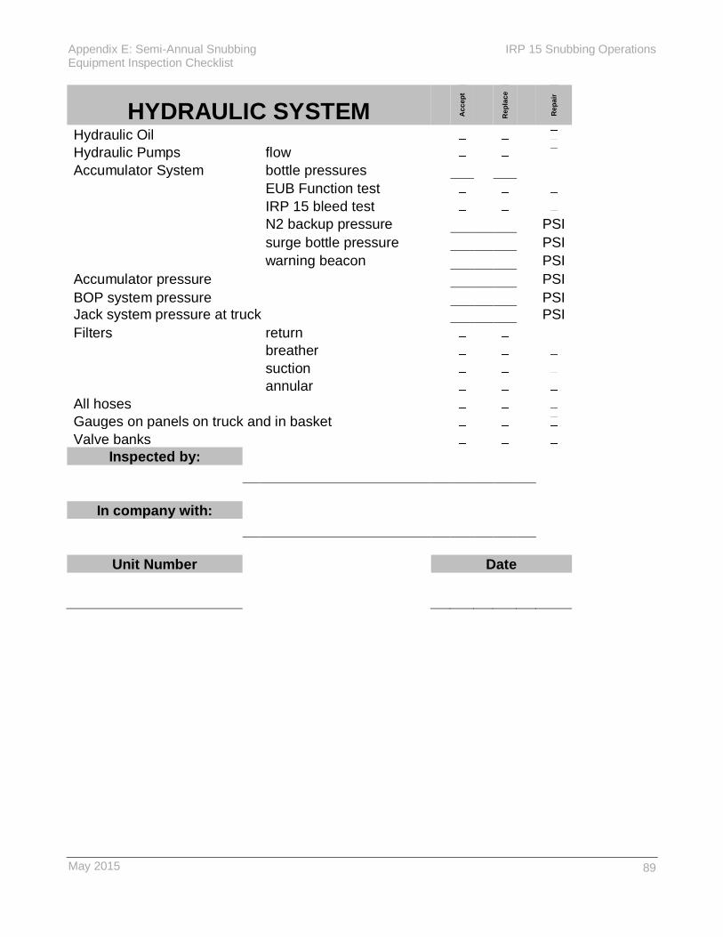
Appendix E: Semi-Annual Snubbing IRP 15 Snubbing Operations Equipment Inspection Checklist
May 2015
89
HYDRAULIC SYSTEM Acc
ep
t
Rep
lac
e
Rep
air
Hydraulic Oil
Hydraulic Pumps flow
Accumulator System bottle pressures
EUB Function test
IRP 15 bleed test
N2 backup pressure PSI
surge bottle pressure PSI
warning beacon PSI
Accumulator pressure PSI
BOP system pressure PSI
Jack system pressure at truck PSI
Filters return
breather
suction
annular
All hoses
Gauges on panels on truck and in basket
Valve banks
Inspected by:
In company with:
Unit Number Date

IRP 15 Snubbing Operations Appendix E: Semi-Annual Snubbing Equipment Inspection Checklist
90 May 2015
CERTIFICATIONS ITEM SERIAL NUMBER EXPIRY DATE
Pipe ram BOP #1
BOP #2
Annular BOP
Working spool #1
Working spool #2
Spacer spool #1
Spacer spool #2
Stationary heavy slip
Stationary snubbing slip
Traveling snubbing slip
Traveling heavy slip
Jack structure
Pick up elevators
Pick up nubbin
Jack plate bolts
Short bales
Traveling plate & bearing
Load plate #1
Load plate #2
Cylinder #1/____________
Cylinder #2/____________
Fall arrest anchor
Eq & B\O flow Tee
EQ valve
B/O valve
Piston separator
Equalize line
Spreader Bar
Lifting slings certification available

Appendix F: Electrical Grounding and IRP 15 Snubbing Operations Bonding for Service Rigs
May 2015
91
Appendix F: Electrical Grounding and Bonding for Service Rigs
The following information is taken from from Alberta Municipal Affairs Electrical Safety Information
Bulletin CEC-10 (Rev-7) October 2009 pages 6 through 9. See References for more details and
website link.

IRP 15 Snubbing Operations Appendix F: Electrical Grounding and Bonding for Service Rigs
92 May 2015
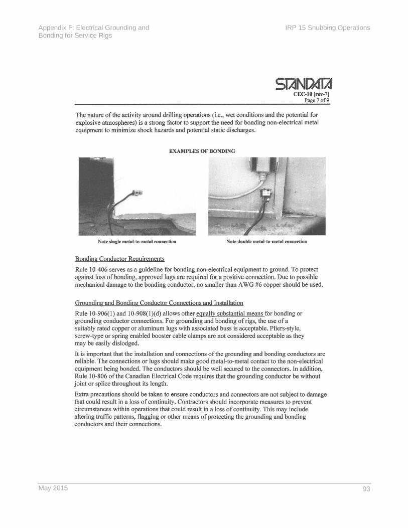
Appendix F: Electrical Grounding and IRP 15 Snubbing Operations Bonding for Service Rigs
May 2015
93

IRP 15 Snubbing Operations Appendix F: Electrical Grounding and Bonding for Service Rigs
94 May 2015

Appendix F: Electrical Grounding and IRP 15 Snubbing Operations Bonding for Service Rigs
May 2015
95


Appendix G: Heat Stress Quick Card IRP 15 Snubbing Operations
May 2015
97
Appendix G: Heat Stress Quick Card

IRP 15 Snubbing Operations Appendix G: Heat Stress Quick Card
98 May 2015

May 2015
99
Appendix H: Cold Weather Exposure Chart – ACGIH

IRP 15 Snubbing Operations Appendix H: Cold Weather Exposure Chart – ACGIH
100 May 2015
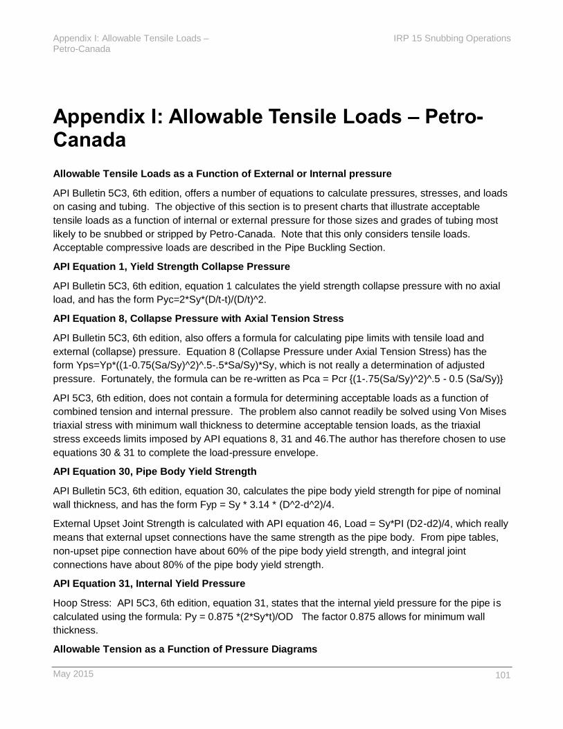
Appendix I: Allowable Tensile Loads – IRP 15 Snubbing Operations Petro-Canada
May 2015
101
Appendix I: Allowable Tensile Loads – Petro-Canada
Allowable Tensile Loads as a Function of External or Internal pressure
API Bulletin 5C3, 6th edition, offers a number of equations to calculate pressures, stresses, and loads
on casing and tubing. The objective of this section is to present charts that illustrate acceptable
tensile loads as a function of internal or external pressure for those sizes and grades of tubing most
likely to be snubbed or stripped by Petro-Canada. Note that this only considers tensile loads.
Acceptable compressive loads are described in the Pipe Buckling Section.
API Equation 1, Yield Strength Collapse Pressure
API Bulletin 5C3, 6th edition, equation 1 calculates the yield strength collapse pressure with no axial
load, and has the form Pyc=2*Sy*(D/t-t)/(D/t)^2.
API Equation 8, Collapse Pressure with Axial Tension Stress
API Bulletin 5C3, 6th edition, also offers a formula for calculating pipe limits with tensile load and
external (collapse) pressure. Equation 8 (Collapse Pressure under Axial Tension Stress) has the
form Yps=Yp*((1-0.75(Sa/Sy)^2)^.5-.5*Sa/Sy)*Sy, which is not really a determination of adjusted
pressure. Fortunately, the formula can be re-written as Pca = Pcr {(1-.75(Sa/Sy)^2)^.5 - 0.5 (Sa/Sy)}
API 5C3, 6th edition, does not contain a formula for determining acceptable loads as a function of
combined tension and internal pressure. The problem also cannot readily be solved using Von Mises
triaxial stress with minimum wall thickness to determine acceptable tension loads, as the triaxial
stress exceeds limits imposed by API equations 8, 31 and 46.The author has therefore chosen to use
equations 30 & 31 to complete the load-pressure envelope.
API Equation 30, Pipe Body Yield Strength
API Bulletin 5C3, 6th edition, equation 30, calculates the pipe body yield strength for pipe of nominal
wall thickness, and has the form Fyp = Sy * 3.14 * (D^2-d^2)/4.
External Upset Joint Strength is calculated with API equation 46, Load = Sy*PI (D2-d2)/4, which really
means that external upset connections have the same strength as the pipe body. From pipe tables,
non-upset pipe connection have about 60% of the pipe body yield strength, and integral joint
connections have about 80% of the pipe body yield strength.
API Equation 31, Internal Yield Pressure
Hoop Stress: API 5C3, 6th edition, equation 31, states that the internal yield pressure for the pipe is
calculated using the formula: Py = 0.875 *(2*Sy*t)/OD The factor 0.875 allows for minimum wall
thickness.
Allowable Tension as a Function of Pressure Diagrams

IRP 15 Snubbing Operations Appendix I: Allowable Tensile Loads – Petro-Canada
102 May 2015
The following charts plot allowable tension as a function of pressure. The objective of the charts is to
illustrate the pressure-load envelope that is defined by API equations 1, 8, 30 and 31. The outer
envelope has no safety factor, whereas the inner envelope applies safety factors for burst, collapse
and tension that are deemed acceptable by Petro-Canada.
These calculations have been provided by Petro-Canada as a reference only. Reliance on this
material alone to the exclusion of other professional advice, experience or resources is imprudent
since each situation is unique.

Appendix I: Allowable Tensile Loads – IRP 15 Snubbing Operations Petro-Canada
May 2015
103
Allowable Tension as a Function of Pressure
Tubing OD: 33.4 mm Grade: J-55
Tubing Wt. 2.56 kg/m Connection: IJ
API equations: where:
Eqn. 1 Yield Strength Collapse Pressure Pyc=2*Sy*((D/t-1)/(D/t)^2 D = Outside diameter
Eqn. 8 Collapse Pressure w. Axial Tension Pca=Pyc{((1-.75(Sa/Sy)^2) .̂5-0.5(Sa/Sy)} d = Inside diameter
Eqn. 30 Pipe Body Yield Strength Fyp = Sy * 3.14 * (D^2-d^2)/4 t = nominal wall thickness
Eqn. 31 Internal Yield Pressure Pyi = 0.875 * (2 * Sy * t) / D Sa = Axial stress
Sy = Yield stress of the steel
Inputs Calculated Pyi = Internal Yield Pressure
Outside diameter (D) 33.40 mm Steel X-sectional area 318.6 mm^2 Pyc = Collapse rating, no axial stress
Inside diameter (d) 26.64 mm Fyp 120753 Newtons Pca = Adjusted collapse rating
Nom. wall thickness (t) 3.38 mm Pyi 67119 kPa Fyp = Pipe body yeld strength
Steel yield strength (Sy) 379 Mpa Pyc -68945 kPa 1kPa = 100 dyne/mm^2
Joint Efficiency (JE) 80 % 1 Newton = 100,000 dynes
Safety Factor, Tension 1.25 EUE = 100%
Safety Factor, Burst 1.20 Joint IJ = 80% Yield Sy of J-55 = 379 Mpa
Safety Factor, Collapse 1.10 Efficiencies NUE = 60% Strengths Sy of L-80 = 551 Mpa
Allowable Tension as a Function of Pressure
These calculations have been provided by Petro-Canada as a reference only. Reliance on this material alone to the exclusion of other
professional advice, experience or resources is imprudent since each situation is unique.
Allowable pressures and tensile loads should be reduced to 75% of pressures & load indicated on the inner envelope if the tubing is old, if there
is potential for corrosion, or if the H2S content in the gas is greater than 1% (10,000 ppm).
-70000
-60000
-50000
-40000
-30000
-20000
-10000
0
10000
20000
30000
40000
50000
60000
70000
0
20
00
40
00
60
00
80
00
10
00
0
Tensile Load, decaNewtons
Pre
ssu
re,
kP
a
<=
==
Co
llap
se
B
urs
t==
=> Burst, 100%
Collapse, 100%
Tension, 100%
Burst, SF = 1.2
Collapse, SF = 1.1
Tension, SF = 1.25
Chart 1: Tubing OD 33.4 mm Grade J-55 Tubing Wt. 2.56 Kg/m Connection IJ
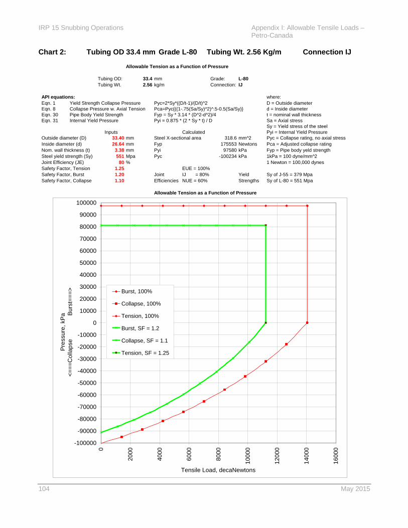
IRP 15 Snubbing Operations Appendix I: Allowable Tensile Loads – Petro-Canada
104 May 2015
Allowable Tension as a Function of Pressure
Tubing OD: 33.4 mm Grade: L-80
Tubing Wt. 2.56 kg/m Connection: IJ
API equations: where:
Eqn. 1 Yield Strength Collapse Pressure Pyc=2*Sy*((D/t-1)/(D/t)^2 D = Outside diameter
Eqn. 8 Collapse Pressure w. Axial Tension Pca=Pyc{((1-.75(Sa/Sy)^2) .̂5-0.5(Sa/Sy)} d = Inside diameter
Eqn. 30 Pipe Body Yield Strength Fyp = Sy * 3.14 * (D^2-d^2)/4 t = nominal wall thickness
Eqn. 31 Internal Yield Pressure Pyi = 0.875 * (2 * Sy * t) / D Sa = Axial stress
Sy = Yield stress of the steel
Inputs Calculated Pyi = Internal Yield Pressure
Outside diameter (D) 33.40 mm Steel X-sectional area 318.6 mm^2 Pyc = Collapse rating, no axial stress
Inside diameter (d) 26.64 mm Fyp 175553 Newtons Pca = Adjusted collapse rating
Nom. wall thickness (t) 3.38 mm Pyi 97580 kPa Fyp = Pipe body yeld strength
Steel yield strength (Sy) 551 Mpa Pyc -100234 kPa 1kPa = 100 dyne/mm^2
Joint Efficiency (JE) 80 % 1 Newton = 100,000 dynes
Safety Factor, Tension 1.25 EUE = 100%
Safety Factor, Burst 1.20 Joint IJ = 80% Yield Sy of J-55 = 379 Mpa
Safety Factor, Collapse 1.10 Efficiencies NUE = 60% Strengths Sy of L-80 = 551 Mpa
Allowable Tension as a Function of Pressure
Allowable pressures and tensile loads should be reduced to 75% of pressures & load indicated on the inner envelope if the tubing is old, if there
is potential for corrosion, or if the H2S content in the gas is greater than 1% (10,000 ppm).
These calculations have been provided by Petro-Canada as a reference only. Reliance on this material alone to the exclusion of other
professional advice, experience or resources is imprudent since each situation is unique.
-100000
-90000
-80000
-70000
-60000
-50000
-40000
-30000
-20000
-10000
0
10000
20000
30000
40000
50000
60000
70000
80000
90000
100000
0
20
00
40
00
60
00
80
00
10
00
0
12
00
0
14
00
0
16
00
0
Tensile Load, decaNewtons
Pre
ssu
re,
kP
a
<=
==
Co
llap
se
B
urs
t==
=> Burst, 100%
Collapse, 100%
Tension, 100%
Burst, SF = 1.2
Collapse, SF = 1.1
Tension, SF = 1.25
Chart 2: Tubing OD 33.4 mm Grade L-80 Tubing Wt. 2.56 Kg/m Connection IJ

Appendix I: Allowable Tensile Loads – IRP 15 Snubbing Operations Petro-Canada
May 2015
105
Allowable Tension as a Function of Pressure
Tubing OD: 42.2 mm Grade: J-55
Tubing Wt. 3.47 kg/m Connection: IJ
API equations: where:
Eqn. 1 Yield Strength Collapse Pressure Pyc=2*Sy*((D/t-1)/(D/t)^2 D = Outside diameter
Eqn. 8 Collapse Pressure w. Axial Tension Pca=Pyc{((1-.75(Sa/Sy)^2) .̂5-0.5(Sa/Sy)} d = Inside diameter
Eqn. 30 Pipe Body Yield Strength Fyp = Sy * 3.14 * (D^2-d^2)/4 t = nominal wall thickness
Eqn. 31 Internal Yield Pressure Pyi = 0.875 * (2 * Sy * t) / D Sa = Axial stress
Sy = Yield stress of the steel
Inputs Calculated Pyi = Internal Yield Pressure
Outside diameter (D) 42.20 mm Steel X-sectional area 433.6 mm^2 Pyc = Collapse rating, no axial stress
Inside diameter (d) 35.05 mm Fyp 164329 Newtons Pca = Adjusted collapse rating
Nom. wall thickness (t) 3.58 mm Pyi 56188 kPa Fyp = Pipe body yeld strength
Steel yield strength (Sy) 379 Mpa Pyc -58774 kPa 1kPa = 100 dyne/mm^2
Joint Efficiency (JE) 80 % 1 Newton = 100,000 dynes
Safety Factor, Tension 1.25 EUE = 100%
Safety Factor, Burst 1.20 Joint IJ = 80% Yield Sy of J-55 = 379 Mpa
Safety Factor, Collapse 1.10 Efficiencies NUE = 60% Strengths Sy of L-80 = 551 Mpa
Allowable Tension as a Function of Pressure
Allowable pressures and tensile loads should be reduced to 75% of pressures & load indicated on the inner envelope if the tubing is old, if there
is potential for corrosion, or if the H2S content in the gas is greater than 1% (10,000 ppm).
These calculations have been provided by Petro-Canada as a reference only. Reliance on this material alone to the exclusion of other
professional advice, experience or resources is imprudent since each situation is unique.
-60000
-50000
-40000
-30000
-20000
-10000
0
10000
20000
30000
40000
50000
60000
0
20
00
40
00
60
00
80
00
10
00
0
12
00
0
14
00
0
Tensile Load, decaNewtons
Pre
ssu
re,
kP
a
<=
==
Co
llap
se
B
urs
t==
=> Burst, 100%
Collapse, 100%
Tension, 100%
Burst, SF = 1.2
Collapse, SF = 1.1
Tension, SF = 1.25
Chart 3: Tubing OD 42.2 mm Grade J-55 Tubing Wt. 3.47 Kg/m Connection IJ
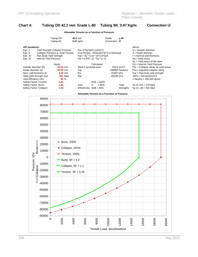
IRP 15 Snubbing Operations Appendix I: Allowable Tensile Loads – Petro-Canada
106 May 2015
Allowable Tension as a Function of Pressure
Tubing OD: 42.2 mm Grade: L-80
Tubing Wt. 3.47 kg/m Connection: IJ
API equations: where:
Eqn. 1 Yield Strength Collapse Pressure Pyc=2*Sy*((D/t-1)/(D/t)^2 D = Outside diameter
Eqn. 8 Collapse Pressure w. Axial Tension Pca=Pyc{((1-.75(Sa/Sy)^2) .̂5-0.5(Sa/Sy)} d = Inside diameter
Eqn. 30 Pipe Body Yield Strength Fyp = Sy * 3.14 * (D^2-d^2)/4 t = nominal wall thickness
Eqn. 31 Internal Yield Pressure Pyi = 0.875 * (2 * Sy * t) / D Sa = Axial stress
Sy = Yield stress of the steel
Inputs Calculated Pyi = Internal Yield Pressure
Outside diameter (D) 42.20 mm Steel X-sectional area 433.6 mm^2 Pyc = Collapse rating, no axial stress
Inside diameter (d) 35.05 mm Fyp 238905 Newtons Pca = Adjusted collapse rating
Nom. wall thickness (t) 3.58 mm Pyi 81687 kPa Fyp = Pipe body yeld strength
Steel yield strength (Sy) 551 Mpa Pyc -85448 kPa 1kPa = 100 dyne/mm^2
Joint Efficiency (JE) 80 % 1 Newton = 100,000 dynes
Safety Factor, Tension 1.25 EUE = 100%
Safety Factor, Burst 1.20 Joint IJ = 80% Yield Sy of J-55 = 379 Mpa
Safety Factor, Collapse 1.10 Efficiencies NUE = 60% Strengths Sy of L-80 = 551 Mpa
Allowable Tension as a Function of Pressure
Allowable pressures and tensile loads should be reduced to 75% of pressures & load indicated on the inner envelope if the tubing is old, if there
is potential for corrosion, or if the H2S content in the gas is greater than 1% (10,000 ppm).
These calculations have been provided by Petro-Canada as a reference only. Reliance on this material alone to the exclusion of other
professional advice, experience or resources is imprudent since each situation is unique.
-90000
-80000
-70000
-60000
-50000
-40000
-30000
-20000
-10000
0
10000
20000
30000
40000
50000
60000
70000
80000
90000
0
20
00
40
00
60
00
80
00
10
00
0
12
00
0
14
00
0
16
00
0
18
00
0
20
00
0
Tensile Load, decaNewtons
Pre
ssu
re,
kP
a
<=
==
Co
llap
se
B
urs
t==
=> Burst, 100%
Collapse, 100%
Tension, 100%
Burst, SF = 1.2
Collapse, SF = 1.1
Tension, SF = 1.25
Chart 4: Tubing OD 42.2 mm Grade L-80 Tubing Wt. 3.47 Kg/m Connection IJ

Appendix I: Allowable Tensile Loads – IRP 15 Snubbing Operations Petro-Canada
May 2015
107
Allowable Tension as a Function of Pressure
Tubing OD: 48.3 mm Grade: J-55
Tubing Wt. 4.11 kg/m Connection: IJ
API equations: where:
Eqn. 1 Yield Strength Collapse Pressure Pyc=2*Sy*((D/t-1)/(D/t)^2 D = Outside diameter
Eqn. 8 Collapse Pressure w. Axial Tension Pca=Pyc{((1-.75(Sa/Sy)^2) .̂5-0.5(Sa/Sy)} d = Inside diameter
Eqn. 30 Pipe Body Yield Strength Fyp = Sy * 3.14 * (D^2-d^2)/4 t = nominal wall thickness
Eqn. 31 Internal Yield Pressure Pyi = 0.875 * (2 * Sy * t) / D Sa = Axial stress
Sy = Yield stress of the steel
Inputs Calculated Pyi = Internal Yield Pressure
Outside diameter (D) 48.30 mm Steel X-sectional area 518.8 mm^2 Pyc = Collapse rating, no axial stress
Inside diameter (d) 40.89 mm Fyp 196627 Newtons Pca = Adjusted collapse rating
Nom. wall thickness (t) 3.71 mm Pyi 50877 kPa Fyp = Pipe body yeld strength
Steel yield strength (Sy) 379 Mpa Pyc -53685 kPa 1kPa = 100 dyne/mm^2
Joint Efficiency (JE) 80 % 1 Newton = 100,000 dynes
Safety Factor, Tension 1.25 EUE = 100%
Safety Factor, Burst 1.20 Joint IJ = 80% Yield Sy of J-55 = 379 Mpa
Safety Factor, Collapse 1.10 Efficiencies NUE = 60% Strengths Sy of L-80 = 551 Mpa
Allowable Tension as a Function of Pressure
Allowable pressures and tensile loads should be reduced to 75% of pressures & load indicated on the inner envelope if the tubing is old, if there
is potential for corrosion, or if the H2S content in the gas is greater than 1% (10,000 ppm).
These calculations have been provided by Petro-Canada as a reference only. Reliance on this material alone to the exclusion of other
professional advice, experience or resources is imprudent since each situation is unique.
-60000
-50000
-40000
-30000
-20000
-10000
0
10000
20000
30000
40000
50000
60000
0
20
00
40
00
60
00
80
00
10
00
0
12
00
0
14
00
0
16
00
0
18
00
0
Tensile Load, decaNewtons
Pre
ssu
re,
kP
a
<=
==
Co
llap
se
B
urs
t==
=>
Burst, 100%
Collapse, 100%
Tension, 100%
Burst, SF = 1.2
Collapse, SF = 1.1
Tension, SF = 1.25
Chart 5: Tubing OD 48.3 mm Grade J-55 Tubing Wt. 4.11 Kg/m Connection IJ

IRP 15 Snubbing Operations Appendix I: Allowable Tensile Loads – Petro-Canada
108 May 2015
Allowable Tension as a Function of Pressure
Tubing OD: 48.3 mm Grade: L-80
Tubing Wt. 4.11 kg/m Connection: IJ
API equations: where:
Eqn. 1 Yield Strength Collapse Pressure Pyc=2*Sy*((D/t-1)/(D/t)^2 D = Outside diameter
Eqn. 8 Collapse Pressure w. Axial Tension Pca=Pyc{((1-.75(Sa/Sy)^2) .̂5-0.5(Sa/Sy)} d = Inside diameter
Eqn. 30 Pipe Body Yield Strength Fyp = Sy * 3.14 * (D^2-d^2)/4 t = nominal wall thickness
Eqn. 31 Internal Yield Pressure Pyi = 0.875 * (2 * Sy * t) / D Sa = Axial stress
Sy = Yield stress of the steel
Inputs Calculated Pyi = Internal Yield Pressure
Outside diameter (D) 48.30 mm Steel X-sectional area 518.8 mm^2 Pyc = Collapse rating, no axial stress
Inside diameter (d) 40.89 mm Fyp 285861 Newtons Pca = Adjusted collapse rating
Nom. wall thickness (t) 3.71 mm Pyi 73966 kPa Fyp = Pipe body yeld strength
Steel yield strength (Sy) 551 Mpa Pyc -78048 kPa 1kPa = 100 dyne/mm^2
Joint Efficiency (JE) 80 % 1 Newton = 100,000 dynes
Safety Factor, Tension 1.25 EUE = 100%
Safety Factor, Burst 1.20 Joint IJ = 80% Yield Sy of J-55 = 379 Mpa
Safety Factor, Collapse 1.10 Efficiencies NUE = 60% Strengths Sy of L-80 = 551 Mpa
Allowable Tension as a Function of Pressure
Allowable pressures and tensile loads should be reduced to 75% of pressures & load indicated on the inner envelope if the tubing is old, if there
is potential for corrosion, or if the H2S content in the gas is greater than 1% (10,000 ppm).
These calculations have been provided by Petro-Canada as a reference only. Reliance on this material alone to the exclusion of other
professional advice, experience or resources is imprudent since each situation is unique.
-80000
-70000
-60000
-50000
-40000
-30000
-20000
-10000
0
10000
20000
30000
40000
50000
60000
70000
80000
0
20
00
40
00
60
00
80
00
10
00
0
12
00
0
14
00
0
16
00
0
18
00
0
20
00
0
22
00
0
24
00
0
Tensile Load, decaNewtons
Pre
ssu
re,
kP
a
<=
==
Co
llap
se
B
urs
t==
=> Burst, 100%
Collapse, 100%
Tension, 100%
Burst, SF = 1.2
Collapse, SF = 1.1
Tension, SF = 1.25
Chart 6: Tubing OD 48.3 mm Grade L-80 Tubing Wt. 4.11 Kg/m Connection IJ

Appendix I: Allowable Tensile Loads – IRP 15 Snubbing Operations Petro-Canada
May 2015
109
Allowable Tension as a Function of Pressure
Tubing OD: 52.4 mm Grade: J-55
Tubing Wt. 4.85 kg/m Connection: IJ
API equations: where:
Eqn. 1 Yield Strength Collapse Pressure Pyc=2*Sy*((D/t-1)/(D/t)^2 D = Outside diameter
Eqn. 8 Collapse Pressure w. Axial Tension Pca=Pyc{((1-.75(Sa/Sy)^2) .̂5-0.5(Sa/Sy)} d = Inside diameter
Eqn. 30 Pipe Body Yield Strength Fyp = Sy * 3.14 * (D^2-d^2)/4 t = nominal wall thickness
Eqn. 31 Internal Yield Pressure Pyi = 0.875 * (2 * Sy * t) / D Sa = Axial stress
Sy = Yield stress of the steel
Inputs Calculated Pyi = Internal Yield Pressure
Outside diameter (D) 52.40 mm Steel X-sectional area 602.3 mm^2 Pyc = Collapse rating, no axial stress
Inside diameter (d) 44.48 mm Fyp 228280 Newtons Pca = Adjusted collapse rating
Nom. wall thickness (t) 3.96 mm Pyi 50123 kPa Fyp = Pipe body yeld strength
Steel yield strength (Sy) 379 Mpa Pyc -52955 kPa 1kPa = 100 dyne/mm^2
Joint Efficiency (JE) 90 % 1 Newton = 100,000 dynes
Safety Factor, Tension 1.25 EUE = 100%
Safety Factor, Burst 1.20 Joint IJ = 80% Yield Sy of J-55 = 379 Mpa
Safety Factor, Collapse 1.10 Efficiencies NUE = 60% Strengths Sy of L-80 = 551 Mpa
Allowable Tension as a Function of Pressure
Allowable pressures and tensile loads should be reduced to 75% of pressures & load indicated on the inner envelope if the tubing is old, if there
is potential for corrosion, or if the H2S content in the gas is greater than 1% (10,000 ppm). These calculations have been provided by Petro-Canada as a reference only. Reliance on this material alone to the exclusion of other
professional advice, experience or resources is imprudent since each situation is unique.
-60000
-50000
-40000
-30000
-20000
-10000
0
10000
20000
30000
40000
50000
60000
0
20
00
40
00
60
00
80
00
10
00
0
12
00
0
14
00
0
16
00
0
18
00
0
20
00
0
22
00
0
24
00
0
Tensile Load, decaNewtons
Pre
ssu
re,
kP
a
<=
==
Colla
pse
B
urs
t==
=> Burst, 100%
Collapse, 100%
Tension, 100%
Burst, SF = 1.2
Collapse, SF = 1.1
Tension, SF = 1.25
Chart 7: Tubing OD 52.4 mm Grade J-55 Tubing Wt. 4.85 Kg/m Connection IJ

IRP 15 Snubbing Operations Appendix I: Allowable Tensile Loads – Petro-Canada
110 May 2015
Allowable Tension as a Function of Pressure
Tubing OD: 52.4 mm Grade: L-80
Tubing Wt. 4.85 kg/m Connection: IJ
API equations: where:
Eqn. 1 Yield Strength Collapse Pressure Pyc=2*Sy*((D/t-1)/(D/t)^2 D = Outside diameter
Eqn. 8 Collapse Pressure w. Axial Tension Pca=Pyc{((1-.75(Sa/Sy)^2) .̂5-0.5(Sa/Sy)} d = Inside diameter
Eqn. 30 Pipe Body Yield Strength Fyp = Sy * 3.14 * (D^2-d^2)/4 t = nominal wall thickness
Eqn. 31 Internal Yield Pressure Pyi = 0.875 * (2 * Sy * t) / D Sa = Axial stress
Sy = Yield stress of the steel
Inputs Calculated Pyi = Internal Yield Pressure
Outside diameter (D) 52.40 mm Steel X-sectional area 602.3 mm^2 Pyc = Collapse rating, no axial stress
Inside diameter (d) 44.48 mm Fyp 331880 Newtons Pca = Adjusted collapse rating
Nom. wall thickness (t) 3.96 mm Pyi 72871 kPa Fyp = Pipe body yeld strength
Steel yield strength (Sy) 551 Mpa Pyc -76987 kPa 1kPa = 100 dyne/mm^2
Joint Efficiency (JE) 90 % 1 Newton = 100,000 dynes
Safety Factor, Tension 1.25 EUE = 100%
Safety Factor, Burst 1.20 Joint IJ = 80% Yield Sy of J-55 = 379 Mpa
Safety Factor, Collapse 1.10 Efficiencies NUE = 60% Strengths Sy of L-80 = 551 Mpa
Allowable Tension as a Function of Pressure
Allowable pressures and tensile loads should be reduced to 75% of pressures & load indicated on the inner envelope if the tubing is old, if there
is potential for corrosion, or if the H2S content in the gas is greater than 1% (10,000 ppm).
These calculations have been provided by Petro-Canada as a reference only. Reliance on this material alone to the exclusion of other
professional advice, experience or resources is imprudent since each situation is unique.
-80000
-70000
-60000
-50000
-40000
-30000
-20000
-10000
0
10000
20000
30000
40000
50000
60000
70000
80000
0
20
00
40
00
60
00
80
00
10
00
0
12
00
0
14
00
0
16
00
0
18
00
0
20
00
0
22
00
0
24
00
0
26
00
0
28
00
0
30
00
0
32
00
0
Tensile Load, decaNewtons
Pre
ssu
re,
kP
a
<=
==
Co
llap
se
B
urs
t==
=> Burst, 100%
Collapse, 100%
Tension, 100%
Burst, SF = 1.2
Collapse, SF = 1.1
Tension, SF = 1.25
Chart 8: Tubing OD 52.4 mm Grade L-80 Tubing Wt. 4.85 Kg/m Connection IJ

Appendix I: Allowable Tensile Loads – IRP 15 Snubbing Operations Petro-Canada
May 2015
111
Allowable Tension as a Function of Pressure
Tubing OD: 60.3 mm Grade: J-55
Tubing Wt. 6.99 kg/m Connection: EUE
API equations: where:
Eqn. 1 Yield Strength Collapse Pressure Pyc=2*Sy*((D/t-1)/(D/t)^2 D = Outside diameter
Eqn. 8 Collapse Pressure w. Axial Tension Pca=Pyc{((1-.75(Sa/Sy)^2) .̂5-0.5(Sa/Sy)} d = Inside diameter
Eqn. 30 Pipe Body Yield Strength Fyp = Sy * 3.14 * (D^2-d^2)/4 t = nominal wall thickness
Eqn. 31 Internal Yield Pressure Pyi = 0.875 * (2 * Sy * t) / D Sa = Axial stress
Sy = Yield stress of the steel
Inputs Calculated Pyi = Internal Yield Pressure
Outside diameter (D) 60.30 mm Steel X-sectional area 838.9 mm^2 Pyc = Collapse rating, no axial stress
Inside diameter (d) 50.67 mm Fyp 317937 Newtons Pca = Adjusted collapse rating
Nom. wall thickness (t) 4.82 mm Pyi 52961 kPa Fyp = Pipe body yeld strength
Steel yield strength (Sy) 379 Mpa Pyc -55694 kPa 1kPa = 100 dyne/mm^2
Joint Efficiency (JE) 100 % 1 Newton = 100,000 dynes
Safety Factor, Tension 1.25 EUE = 100%
Safety Factor, Burst 1.20 Joint IJ = 80% Yield Sy of J-55 = 379 Mpa
Safety Factor, Collapse 1.10 Efficiencies NUE = 60% Strengths Sy of L-80 = 551 Mpa
Allowable Tension as a Function of Pressure
Allowable pressures and tensile loads should be reduced to 75% of pressures & load indicated on the inner envelope if the tubing is old, if there
is potential for corrosion, or if the H2S content in the gas is greater than 1% (10,000 ppm).
These calculations have been provided by Petro-Canada as a reference only. Reliance on this material alone to the exclusion of other
professional advice, experience or resources is imprudent since each situation is unique.
-60000
-50000
-40000
-30000
-20000
-10000
0
10000
20000
30000
40000
50000
60000
0
20
00
40
00
60
00
80
00
10
00
0
12
00
0
14
00
0
16
00
0
18
00
0
20
00
0
22
00
0
24
00
0
26
00
0
28
00
0
30
00
0
32
00
0
34
00
0
Tensile Load, decaNewtons
Pre
ssu
re,
kP
a
<=
==
Colla
pse
B
urs
t==
=> Burst, 100%
Collapse, 100%
Tension, 100%
Burst, SF = 1.2
Collapse, SF = 1.1
Tension, SF = 1.25
Chart 9: Tubing OD 60.3 mm Grade J-55 Tubing Wt. 6.99 Kg/m Connection EUE

IRP 15 Snubbing Operations Appendix I: Allowable Tensile Loads – Petro-Canada
112 May 2015
Allowable Tension as a Function of Pressure
Tubing OD: 60.3 mm Grade: L-80
Tubing Wt. 6.99 kg/m Connection: EUE
API equations: where:
Eqn. 1 Yield Strength Collapse Pressure Pyc=2*Sy*((D/t-1)/(D/t)^2 D = Outside diameter
Eqn. 8 Collapse Pressure w. Axial Tension Pca=Pyc{((1-.75(Sa/Sy)^2) .̂5-0.5(Sa/Sy)} d = Inside diameter
Eqn. 30 Pipe Body Yield Strength Fyp = Sy * 3.14 * (D^2-d^2)/4 t = nominal wall thickness
Eqn. 31 Internal Yield Pressure Pyi = 0.875 * (2 * Sy * t) / D Sa = Axial stress
Sy = Yield stress of the steel
Inputs Calculated Pyi = Internal Yield Pressure
Outside diameter (D) 60.30 mm Steel X-sectional area 838.9 mm^2 Pyc = Collapse rating, no axial stress
Inside diameter (d) 50.67 mm Fyp 462225 Newtons Pca = Adjusted collapse rating
Nom. wall thickness (t) 4.82 mm Pyi 76996 kPa Fyp = Pipe body yeld strength
Steel yield strength (Sy) 551 Mpa Pyc -80969 kPa 1kPa = 100 dyne/mm^2
Joint Efficiency (JE) 100 % 1 Newton = 100,000 dynes
Safety Factor, Tension 1.25 EUE = 100%
Safety Factor, Burst 1.20 Joint IJ = 80% Yield Sy of J-55 = 379 Mpa
Safety Factor, Collapse 1.10 Efficiencies NUE = 60% Strengths Sy of L-80 = 551 Mpa
Allowable Tension as a Function of Pressure
Allowable pressures and tensile loads should be reduced to 75% of pressures & load indicated on the inner envelope if the tubing is old, if there
is potential for corrosion, or if the H2S content in the gas is greater than 1% (10,000 ppm).
These calculations have been provided by Petro-Canada as a reference only. Reliance on this material alone to the exclusion of other
professional advice, experience or resources is imprudent since each situation is unique.
-80000
-70000
-60000
-50000
-40000
-30000
-20000
-10000
0
10000
20000
30000
40000
50000
60000
70000
80000
0
50
00
10
00
0
15
00
0
20
00
0
25
00
0
30
00
0
35
00
0
40
00
0
45
00
0
50
00
0
Tensile Load, decaNewtons
Pre
ssu
re,
kP
a
<=
==
Co
llap
se
B
urs
t==
=> Burst, 100%
Collapse, 100%
Tension, 100%
Burst, SF = 1.2
Collapse, SF = 1.1
Tension, SF = 1.25
Chart 10: Tubing OD 60.3 mm Grade I-80 Tubing Wt. 6.99 Kg/m Connection EUE

Appendix I: Allowable Tensile Loads – IRP 15 Snubbing Operations Petro-Canada
May 2015
113
Allowable Tension as a Function of Pressure
Tubing OD: 73.0 mm Grade: J-55
Tubing Wt. 9.67 kg/m Connection: EUE
API equations: where:
Eqn. 1 Yield Strength Collapse Pressure Pyc=2*Sy*((D/t-1)/(D/t)^2 D = Outside diameter
Eqn. 8 Collapse Pressure w. Axial Tension Pca=Pyc{((1-.75(Sa/Sy)^2) .̂5-0.5(Sa/Sy)} d = Inside diameter
Eqn. 30 Pipe Body Yield Strength Fyp = Sy * 3.14 * (D^2-d^2)/4 t = nominal wall thickness
Eqn. 31 Internal Yield Pressure Pyi = 0.875 * (2 * Sy * t) / D Sa = Axial stress
Sy = Yield stress of the steel
Inputs Calculated Pyi = Internal Yield Pressure
Outside diameter (D) 73.00 mm Steel X-sectional area 1165.7 mm^2 Pyc = Collapse rating, no axial stress
Inside diameter (d) 62.00 mm Fyp 441810 Newtons Pca = Adjusted collapse rating
Nom. wall thickness (t) 5.50 mm Pyi 49971 kPa Fyp = Pipe body yeld strength
Steel yield strength (Sy) 379 Mpa Pyc -52807 kPa 1kPa = 100 dyne/mm^2
Joint Efficiency (JE) 100 % 1 Newton = 100,000 dynes
Safety Factor, Tension 1.25 EUE = 100%
Safety Factor, Burst 1.20 Joint IJ = 80% Yield Sy of J-55 = 379 Mpa
Safety Factor, Collapse 1.10 Efficiencies NUE = 60% Strengths Sy of L-80 = 551 Mpa
Allowable Tension as a Function of Pressure
Allowable pressures and tensile loads should be reduced to 75% of pressures & load indicated on the inner envelope if the tubing is old, if there
is potential for corrosion, or if the H2S content in the gas is greater than 1% (10,000 ppm).
These calculations have been provided by Petro-Canada as a reference only. Reliance on this material alone to the exclusion of other
professional advice, experience or resources is imprudent since each situation is unique.
-60000
-50000
-40000
-30000
-20000
-10000
0
10000
20000
30000
40000
50000
60000
0
50
00
10
00
0
15
00
0
20
00
0
25
00
0
30
00
0
35
00
0
40
00
0
45
00
0
50
00
0
Tensile Load, decaNewtons
Pre
ssu
re,
kP
a
<=
==
Co
llap
se
B
urs
t==
=> Burst, 100%
Collapse, 100%
Tension, 100%
Burst, SF = 1.2
Collapse, SF = 1.1
Tension, SF = 1.25
Chart 11: Tubing OD 73.0 mm Grade J-55 Tubing Wt. 9.67 Kg/m Connection EUE

IRP 15 Snubbing Operations Appendix I: Allowable Tensile Loads – Petro-Canada
114 May 2015
Allowable Tension as a Function of Pressure
Tubing OD: 73.0 mm Grade: L-80
Tubing Wt. 9.67 kg/m Connection: EUE
API equations: where:
Eqn. 1 Yield Strength Collapse Pressure Pyc=2*Sy*((D/t-1)/(D/t)^2 D = Outside diameter
Eqn. 8 Collapse Pressure w. Axial Tension Pca=Pyc{((1-.75(Sa/Sy)^2) .̂5-0.5(Sa/Sy)} d = Inside diameter
Eqn. 30 Pipe Body Yield Strength Fyp = Sy * 3.14 * (D^2-d^2)/4 t = nominal wall thickness
Eqn. 31 Internal Yield Pressure Pyi = 0.875 * (2 * Sy * t) / D Sa = Axial stress
Sy = Yield stress of the steel
Inputs Calculated Pyi = Internal Yield Pressure
Outside diameter (D) 73.00 mm Steel X-sectional area 1165.7 mm^2 Pyc = Collapse rating, no axial stress
Inside diameter (d) 62.00 mm Fyp 642314 Newtons Pca = Adjusted collapse rating
Nom. wall thickness (t) 5.50 mm Pyi 72649 kPa Fyp = Pipe body yeld strength
Steel yield strength (Sy) 551 Mpa Pyc -76772 kPa 1kPa = 100 dyne/mm^2
Joint Efficiency (JE) 100 % 1 Newton = 100,000 dynes
Safety Factor, Tension 1.25 EUE = 100%
Safety Factor, Burst 1.20 Joint IJ = 80% Yield Sy of J-55 = 379 Mpa
Safety Factor, Collapse 1.10 Efficiencies NUE = 60% Strengths Sy of L-80 = 551 Mpa
Allowable Tension as a Function of Pressure
Allowable pressures and tensile loads should be reduced to 75% of pressures & load indicated on the inner envelope if the tubing is old, if there
is potential for corrosion, or if the H2S content in the gas is greater than 1% (10,000 ppm). These calculations have been provided by Petro-Canada as a reference only. Reliance on this material alone to the exclusion of other
professional advice, experience or resources is imprudent since each situation is unique.
-80000
-70000
-60000
-50000
-40000
-30000
-20000
-10000
0
10000
20000
30000
40000
50000
60000
70000
80000
0
50
00
10
00
0
15
00
0
20
00
0
25
00
0
30
00
0
35
00
0
40
00
0
45
00
0
50
00
0
55
00
0
60
00
0
65
00
0
70
00
0
Tensile Load, decaNewtons
Pre
ssu
re,
kP
a
<=
==
Colla
pse
B
urs
t==
=> Burst, 100%
Collapse, 100%
Tension, 100%
Burst, SF = 1.2
Collapse, SF = 1.1
Tension, SF = 1.25
Chart 12: Tubing OD 73.0 mm Grade L-80 Tubing Wt. 9.67 Kg/m Connection EUE

Appendix I: Allowable Tensile Loads – IRP 15 Snubbing Operations Petro-Canada
May 2015
115
Allowable Tension as a Function of Pressure
Tubing OD: 88.9 mm Grade: J-55
Tubing Wt. 13.84 kg/m Connection: EUE
API equations: where:
Eqn. 1 Yield Strength Collapse Pressure Pyc=2*Sy*((D/t-1)/(D/t)^2 D = Outside diameter
Eqn. 8 Collapse Pressure w. Axial Tension Pca=Pyc{((1-.75(Sa/Sy)^2) .̂5-0.5(Sa/Sy)} d = Inside diameter
Eqn. 30 Pipe Body Yield Strength Fyp = Sy * 3.14 * (D^2-d^2)/4 t = nominal wall thickness
Eqn. 31 Internal Yield Pressure Pyi = 0.875 * (2 * Sy * t) / D Sa = Axial stress
Sy = Yield stress of the steel
Inputs Calculated Pyi = Internal Yield Pressure
Outside diameter (D) 88.90 mm Steel X-sectional area 1669.9 mm^2 Pyc = Collapse rating, no axial stress
Inside diameter (d) 76.00 mm Fyp 632877 Newtons Pca = Adjusted collapse rating
Nom. wall thickness (t) 6.45 mm Pyi 48121 kPa Fyp = Pipe body yeld strength
Steel yield strength (Sy) 379 Mpa Pyc -51005 kPa 1kPa = 100 dyne/mm^2
Joint Efficiency (JE) 100 % 1 Newton = 100,000 dynes
Safety Factor, Tension 1.25 EUE = 100%
Safety Factor, Burst 1.20 Joint IJ = 80% Yield Sy of J-55 = 379 Mpa
Safety Factor, Collapse 1.10 Efficiencies NUE = 60% Strengths Sy of L-80 = 551 Mpa
Allowable Tension as a Function of Pressure
Allowable pressures and tensile loads should be reduced to 75% of pressures & load indicated on the inner envelope if the tubing is old, if there
is potential for corrosion, or if the H2S content in the gas is greater than 1% (10,000 ppm).
These calculations have been provided by Petro-Canada as a reference only. Reliance on this material alone to the exclusion of other
professional advice, experience or resources is imprudent since each situation is unique.
-60000
-50000
-40000
-30000
-20000
-10000
0
10000
20000
30000
40000
50000
60000
0
50
00
10
00
0
15
00
0
20
00
0
25
00
0
30
00
0
35
00
0
40
00
0
45
00
0
50
00
0
55
00
0
60
00
0
65
00
0
70
00
0
Tensile Load, decaNewtons
Pre
ssu
re,
kP
a
<=
==
Co
llap
se
B
urs
t==
=> Burst, 100%
Collapse, 100%
Tension, 100%
Burst, SF = 1.2
Collapse, SF = 1.1
Tension, SF = 1.25
Chart 13: Tubing OD 88.9 mm Grade J-55 Tubing Wt. 13.84 Kg/m Connection EUE

IRP 15 Snubbing Operations Appendix I: Allowable Tensile Loads – Petro-Canada
116 May 2015
Allowable Tension as a Function of Pressure
Tubing OD: 88.9 mm Grade: L-80
Tubing Wt. 13.84 kg/m Connection: EUE
API equations: where:
Eqn. 1 Yield Strength Collapse Pressure Pyc=2*Sy*((D/t-1)/(D/t)^2 D = Outside diameter
Eqn. 8 Collapse Pressure w. Axial Tension Pca=Pyc{((1-.75(Sa/Sy)^2) .̂5-0.5(Sa/Sy)} d = Inside diameter
Eqn. 30 Pipe Body Yield Strength Fyp = Sy * 3.14 * (D^2-d^2)/4 t = nominal wall thickness
Eqn. 31 Internal Yield Pressure Pyi = 0.875 * (2 * Sy * t) / D Sa = Axial stress
Sy = Yield stress of the steel
Inputs Calculated Pyi = Internal Yield Pressure
Outside diameter (D) 88.90 mm Steel X-sectional area 1669.9 mm^2 Pyc = Collapse rating, no axial stress
Inside diameter (d) 76.00 mm Fyp 920093 Newtons Pca = Adjusted collapse rating
Nom. wall thickness (t) 6.45 mm Pyi 69960 kPa Fyp = Pipe body yeld strength
Steel yield strength (Sy) 551 Mpa Pyc -74153 kPa 1kPa = 100 dyne/mm^2
Joint Efficiency (JE) 100 % 1 Newton = 100,000 dynes
Safety Factor, Tension 1.25 EUE = 100%
Safety Factor, Burst 1.20 Joint IJ = 80% Yield Sy of J-55 = 379 Mpa
Safety Factor, Collapse 1.10 Efficiencies NUE = 60% Strengths Sy of L-80 = 551 Mpa
Allowable Tension as a Function of Pressure
Allowable pressures and tensile loads should be reduced to 75% of pressures & load indicated on the inner envelope if the tubing is old, if there
is potential for corrosion, or if the H2S content in the gas is greater than 1% (10,000 ppm).
These calculations have been provided by Petro-Canada as a reference only. Reliance on this material alone to the exclusion of other
professional advice, experience or resources is imprudent since each situation is unique.
-80000
-70000
-60000
-50000
-40000
-30000
-20000
-10000
0
10000
20000
30000
40000
50000
60000
70000
80000
0
50
00
10
00
0
15
00
0
20
00
0
25
00
0
30
00
0
35
00
0
40
00
0
45
00
0
50
00
0
55
00
0
60
00
0
65
00
0
70
00
0
75
00
0
80
00
0
85
00
0
90
00
0
95
00
0
10
00
00
Tensile Load, decaNewtons
Pre
ssu
re,
kP
a
<=
==
Co
llap
se
B
urs
t==
=>
Burst, 100%
Collapse, 100%
Tension, 100%
Burst, SF = 1.2
Collapse, SF = 1.1
Tension, SF = 1.25
Chart 14: Tubing OD 88.9 mm Grade L-80 Tubing Wt. 13.84 Kg/m Connection EUE

Appendix J: Pipe Buckling Forces – IRP 15 Snubbing Operations Petro-Canada
May 2015
117
Pipe Buckling (pipe light condition)
The allowable length of unsupported pipe above the snubbing annular (or stripping pipe rams)
must be determined. The length of unsupported tubing increases when the snubbing annular is
open. The upwards force generated by wellbore pressures increases when a tubing connection
is in the snubbing annular.
Tubing OD 60.30 mm Grade J-55
Tubing weight 6.99 kg/m Connection EUE
Use Johnson's Equation for Short Column Buckling (Local Buckling)
Flb =Sy*As*(1-(L/RG)^2/(2*(SRc)^2))
Use Euler's Equation for Long Column Buckling (Major Axis Buckling)
Feb =(3.14)^2*E*I/(L)^2
Where: As = Steel cross sectional area
Sy = Yield stress of steel
I = Moment of Inertia
RG = Radius of Gyration
SR = Slenderness ratio for a given length
SRc = Critical slenderness ratio
L = Unsupported Length
The safety factor applied to the above equations depends on the strength of the tubing connection.
These calculations have been provided by Petro-Canada as a reference only. Reliance on this material alone to the exclusion
of other professional advice, experience or resources is imprudent since each situation is unique.
Buckling Force vs. Unsupported Length
0
5000
10000
15000
20000
25000
30000
35000
0
500
1000
1500
2000
2500
3000
3500
4000
4500
5000
5500
6000
Unsupported Length, mm
Bu
ckli
ng
Fo
rce,
daN
L = RG x SRc
Local Buckle
(Inelastic)
Major Axis Buckle
(Elastic)
Appendix J: Pipe Buckling Forces – Petro-Canada

IRP 15 Snubbing Operations Appendix J: Pipe Buckling Forces – Petro-Canada
118 May 2015
Pipe Buckling Forces
Pipe Buckling Forces
There are five vertical forces acting
on the tubing string while snubbing
1. Force resulting from well pressure
acting on the cross section of the
tubing string or coupling (Fwp)
2. Gravitational force or weight of
the tubing string (W).
3. Frictional force to push pipe
through the BOPs (Ffric).
4. Force caused by pipe drag on
the casing (Fdrag)
5. Force applied by the snubbing
unit (Fsnub).
Fsnub is the force required to push the tubing into the wellbore.
Maximum Fsnub occurs when pipe is being started into the wellbore, as there is
no pipe weight to counter pressure. Fsnub = Fwp + Ffric.
Force due to friction through the annular BOP is a function of how much hydraulic
pressure is applied to the annular, which in turn is a function of the well pressure.
Conservatively assume that Ffric = 20% of Fwp.
The upwards force generated by wellbore pressures increases when a tubing
connection is in the snubbing annular.
These calculations have been provided by Petro-Canada as a reference only. Reliance on this material alone to the exclusion
of other professional advice, experience or resources is imprudent since each situation is unique.
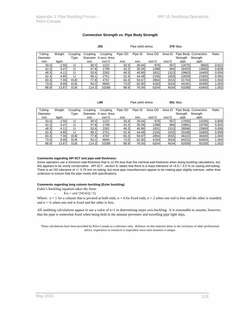
Appendix J: Pipe Buckling Forces – IRP 15 Snubbing Operations Petro-Canada
May 2015
119
Connection Strength vs. Pipe Body Strength
J55 Pipe yield stress 379 Mpa
Tubing Weight Coupling Coupling Coupling Pipe OD Pipe ID Area OD Area ID Pipe Body Connection Ratio
Diameter Type Diameter X-sect. Area Strength Strength
mm kg/m mm mm^2 mm mm mm^2 mm^2 daN daN
33.4 2.56 IJ 39.4 1222 33.4 26.64 876 557 12075 9800 0.812
42.2 3.47 IJ 47.8 1799 42.2 35.05 1398 964 16433 13600 0.828
48.3 4.11 IJ 53.6 2262 48.3 40.89 1831 1313 19663 16400 0.834
52.4 4.85 IJ 59.1 2751 52.4 44.48 2155 1553 22828 21800 0.955
60.3 7.00 EUE 77.8 4767 60.3 50.67 2854 2015 31794 31900 1.003
73.0 9.69 EUE 93.2 6840 73.0 62.00 4183 3018 44181 44300 1.003
88.9 13.87 EUE 114.3 10288 88.9 76.00 6204 4534 63288 63400 1.002
L80 Pipe yield stress 551 Mpa
Tubing Weight Coupling Coupling Coupling Pipe OD Pipe ID Area OD Area ID Pipe Body Connection Ratio
Diameter Type Diameter X-sect. Area Strength Strength
mm kg/m mm mm^2 mm mm mm^2 mm^2 daN daN
33.4 2.56 IJ 39.4 1222 33.4 26.64 876 557 17555 14200 0.809
42.2 3.47 IJ 47.8 1799 42.2 35.05 1398 964 23891 19700 0.825
48.3 4.11 IJ 53.6 2262 48.3 40.89 1831 1313 28586 23900 0.836
52.4 4.85 IJ 59.1 2751 52.4 44.48 2155 1553 33188 31800 0.958
60.3 7.00 EUE 77.8 4767 60.3 50.67 2854 2015 46222 46400 1.004
73.0 9.69 EUE 93.2 6840 73.0 62.00 4183 3018 64231 64500 1.004
88.9 13.87 EUE 114.3 10288 88.9 76.00 6204 4534 92009 92200 1.002
Comments regarding API 5CT and pipe wall thickness:
Comments regarding long column buckling (Euler buckling)
Euler’s buckling equation takes the form:
– Fcr = n•p^2•E•I/(L^2)
These calculations have been provided by Petro-Canada as a reference only. Reliance on this material alone to the exclusion of other professional
advice, experience or resources is imprudent since each situation is unique.
Some operators use a minimum wall thickness that is 12.5% less than the nominal wall thickness when doing buckling calculations, but
this appears to be overly conservative. API 5CT , section 8, states that there is a mass tolerance of +6.5 / -3.5 % on casing and tubing.
There is an OD tolerance of +/- 0.79 mm on tubing, but most pipe manufacturers appear to be making pipe slightly oversize, rather than
undersize to ensure that the pipe meets drift specifications.
Where: n = 1 for a column that is pivoted at both ends, n = 4 for fixed ends, n = 2 when one end is free and the other is rounded,
and n = ¼ when one end is fixed and the other is free..
All snubbing calculations appear to use a value of n=1 in determining major axis buckling. It is reasonable to assume, however,
that the pipe is somewhat fixed when being held in the annular preventer and travelling pipe light slips.

IRP 15 Snubbing Operations Appendix J: Pipe Buckling Forces – Petro-Canada
120 May 2015
Buckling Tables Explanation
Before starting a snubbing job, it is necessary to determine the expected
snubbing force, Fsnub, and the allowable unsupported length of tubing.
Step 1
Step 2 Refer to the buckling worksheet appropriate for the size, weight and grade of tubing
that will be snubbed. There are 14 worksheets, corresponding to the most likely
tubing, connection & grade combinations likely to be snubbed by Petro-Canada.
Tubing Tubing Tubing
Diameter Weight Grade
mm kg/m
33.4 2.56 J-55 or L-80
42.2 3.47 J-55 or L-80
48.3 4.11 J-55 or L-80
52.4 4.85 J-55 or L-80
60.3 6.99 J-55 or L-80
73.0 9.69 J-55 or L-80
88.9 13.87 J-55 or L-80
Use the tables or charts to determine the allowable unsupported length as a
function of wellbore pressure for the tubing, plus when a connection is in the
annular BOP (or stripping pipe rams if the annular is open).
The smaller diameters, 33.4, 42.2, 48.3 & 52.4 mm are likely to have Integral
Joint connections. 33.4, 42.2 & 48.3 mm IJ connections have about 83% of the
strength of the pipe body. Use the 60% curve for these three tubing sizes.
The 52.4 mm IJ connection has ± 95% of the strength of the pipe body. Use the
65% curve for 52.4 mm IJ tubing.
The larger diameters, 60.3, 73.0 and 88.9 mm are likely to have EUE or
premium connections. EUE and premium connections have 100% of the strength
of the pipe body. Use the 70% curve for these 3 sizes.
Step 3 If the wellbore conditions and snubbing lengths are such that snubbing forces
will exceed the limits illustrated in the buckling calculation worksheets, it will
probably be necessary to add liquid to the wellbore so as to reduce the
wellbore pressure and snubbing force required.
If the tubing is N-80 (non sour spec), is old, the wellbore pressure is greater than 5000 psi (35
MPa) or if there is an H2S concentration greater than 1.0% (10,000 ppm), reduce the
unsupported length by 25%.
Referring to the figures on worksheets entitled Low Pressure Snubbing Arrangement and High
Presure Snubbing Arrangement, determine the distance between the snubbing annular and
the lowest attainable position for the travelling, pipe light slips.
These calculations have been provided by Petro-Canada as a reference only. Reliance on this material alone to the exclusion
of other professional advice, experience or resources is imprudent since each situation is unique.
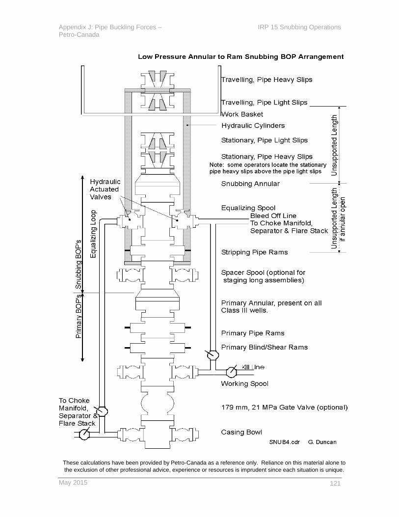
Appendix J: Pipe Buckling Forces – IRP 15 Snubbing Operations Petro-Canada
May 2015
121
These calculations have been provided by Petro-Canada as a reference only. Reliance on this material alone to
the exclusion of other professional advice, experience or resources is imprudent since each situation is unique.

IRP 15 Snubbing Operations Appendix J: Pipe Buckling Forces – Petro-Canada
122 May 2015
These calculations have been provided by Petro-Canada as a reference only. Reliance on this
material alone to the exclusion of other professional advice, experience or resources is imprudent
since each situation is unique.

May 2015
123
Pipe Buckling Calculations Tubing OD 33.40 mm Tubing weight 2.56 kg/m
Grade J-55 Connection IJ
Snubbing Force vs Wellbore Pressure Buckling Force as a Function of Unsupported Length
INPUT Wellbore Snubbing Force Transition Length at Unsupported Unsupported Slenderness Buckling Force, daN
Pipe OD OD 33.40 mm Pressure Tubing in Coupling in to pipe which cplg. Length Length Ratio IJ
Pipe ID ID 26.64 mm kPa Annular, daN Annular, daN heavy, m. neutral, m. (mm) (metres) 100% 60%
Cplg OD CplgOD 39.40 mm 0 0 0 0.0 0.0 0 0.00 0.00 12075 7245
Pipe yield stress Sy 379 MPa 2500 263 367 104.6 146.0 50 0.05 4.68 12063 7238
Modulus Elasticity E 200 GPa 5000 525 733 209.2 292.1 100 0.10 9.36 12024 7215
CALCULATED 7500 788 1100 313.8 438.1 200 0.20 18.73 11872 7123
Area, pipe OD Ao 876 mm^2 10000 1051 1467 418.4 584.1 300 0.30 28.09 11618 6971
Area, pipe ID Ai 557 mm^2 12500 1314 1834 523.1 730.2 400 0.40 37.45 11261 6757
Area, steel As 319 mm^2 15000 1576 2200 627.7 876.2 600 0.60 56.18 10244 6147
Moment of Inertia I 36346 mm^4 17500 1839 2567 732.3 1022.2 800 0.80 74.90 8820 5292
Radius of Gyration RG 10.68 mm 20000 2102 2934 836.9 1168.3 1000 1.00 93.63 6989 4193
Critical Slenderness SRc 102.0 22500 2364 3301 941.5 1314.3 1200 1.20 112.35 4977 2986
Ratio 25000 2627 3667 1046.1 1460.3 1400 1.40 131.08 3657 2194
Cplg x-sect area Acplg 1222 mm^2 27500 2890 4034 1150.7 1606.4 1600 1.60 149.80 2800 1680
EQUATIONS 30000 3153 4401 1255.3 1752.4 1800 1.80 168.53 2212 1327
Area, pipe OD Ao =3.14*(OD^2)/4 32500 3415 4768 1359.9 1898.4 2000 2.00 187.25 1792 1075
Area, pipe ID Ai = 3.14*(ID^2)/4 35000 3678 5134 1464.5 2044.5 2200 2.20 205.98 1481 888
Area, steel As =Ao-Ai 40000 4203 5868 1673.8 2336.6 2400 2.40 224.70 1244 747
Moment of Inertia I =3.14*(OD^4-ID^4)/64 42500 4466 6235 1778.4 2482.6 2600 2.60 243.43 1060 636
Radius of Gyration RG =(I/As)^.5 45000 4729 6601 1883.0 2628.6 2800 2.80 262.15 914 549
Crit.slenderness ratio SRc =3.14*(2*E/Sy)^.5 47500 4992 6968 1987.6 2774.7 3000 3.00 280.88 796 478
Slenderness ratio SR =L/r 50000 5254 7335 2092.2 2920.7 3500 3.50 327.69 585 351
Local Buckle Flb =Sy*As*(1-(L/RG)^2/(2*(SRc)^2)) Note: Above snubbing forces include Above calculations 4000 4.00 374.51 448 269
(Johnson's Eqn, short column) 20% for friction through the annular BOP assume annulus gas has 4500 4.50 421.32 354 212
Major Axis Buckle Feb =(3.14)^2*E*I/(L)^2 Fwp = WP (kPa) * X-area (mm^2) / 10000 a specific gravity = 1.0 5000 5.00 468.13 287 172
(Euler Eqn, long column, pinned ends) Fsnub = Fwp + Ffric = 1.2 x Fwp (air sg = 1.0) 5500 5.50 514.95 237 142
Buckling Load Fb =IF(SR>SRc,Feb,Flb) units: decaNewtons 6000 6.00 561.76 199 119
Example: Wellbore pressure = 17,500 kPa Tubing snubbing force = 1839 daN Allowable unsupported length with tubing in annular BOP 1.5 metres
Coupling snubbing force = 2567 daN Allowable unsupported length, coupling in annular BOP 1.3 metres
These calculations have been provided by Petro-Canada as a reference only. Reliance on this material alone to the exclusion of other professional advice, experience or resources is imprudent since each situation is unique.
Buckling Force vs. Unsupported Length
0
2000
4000
6000
8000
10000
12000
14000
0.0
0
0.5
0
1.0
0
1.5
0
2.0
0
2.5
0
3.0
0
3.5
0
4.0
0
4.5
0
5.0
0
5.5
0
6.0
0
Unsupported Length, metres
B
ucklin
g F
orc
e, d
aN
100%
60%, IJ connection
Snubbing Force vs Wellbore Pressure
0
2000
4000
6000
8000
10000
12000
14000
0
50
00
10
00
0
15
00
0
20
00
0
25
00
0
30
00
0
35
00
0
40
00
0
45
00
0
50
00
0
Wellbore pressure, kPa
Sn
ub
bin
g F
orc
e, d
aN
Tubing in Annular
Coupling in Annular
Chart 15: Tubing OD 33.4 mm Grade J-55 Tubing Wt. 2.56 Kg/m Connection IJ

IRP 15 Snubbing Operations Appendix J: Pipe Buckling Forces – Petro-Canada
124 May 2015
Pipe Buckling Calculations Tubing OD 33.40 mm Tubing weight 2.56 kg/m
Grade L-80 Connection IJ
Snubbing Force vs Wellbore Pressure Buckling Force as a Function of Unsupported Length
INPUT Wellbore Snubbing Force Transition Length at Unsupported Unsupported Slenderness Buckling Force, daN
Pipe OD OD 33.40 mm Pressure Tubing in Coupling in to pipe which cplg. Length Length Ratio IJ
Pipe ID ID 26.64 mm kPa Annular, daN Annular, daN heavy, m. neutral, m. (mm) (metres) 100% 60%
Cplg OD CplgOD 39.40 mm 0 0 0 0.0 0.0 0 0.00 0.00 17555 10533
Pipe yield stress Sy 551 MPa 2500 263 367 104.6 146.0 50 0.05 4.68 17528 10517
Modulus Elasticity E 200 GPa 5000 525 733 209.2 292.1 100 0.10 9.36 17448 10469
CALCULATED 7500 788 1100 313.8 438.1 200 0.20 18.73 17125 10275
Area, pipe OD Ao 876 mm^2 10000 1051 1467 418.4 584.1 300 0.30 28.09 16588 9953
Area, pipe ID Ai 557 mm^2 12500 1314 1834 523.1 730.2 400 0.40 37.45 15835 9501
Area, steel As 319 mm^2 15000 1576 2200 627.7 876.2 600 0.60 56.18 13685 8211
Moment of Inertia I 36346 mm^4 17500 1839 2567 732.3 1022.2 800 0.80 74.90 10675 6405
Radius of Gyration RG 10.68 mm 20000 2102 2934 836.9 1168.3 1000 1.00 93.63 7167 4300
Critical Slenderness SRc 84.6 22500 2364 3301 941.5 1314.3 1200 1.20 112.35 4977 2986
Ratio 25000 2627 3667 1046.1 1460.3 1400 1.40 131.08 3657 2194
Cplg x-sect area Acplg 1222 mm^2 27500 2890 4034 1150.7 1606.4 1600 1.60 149.80 2800 1680
EQUATIONS 30000 3153 4401 1255.3 1752.4 1800 1.80 168.53 2212 1327
Area, pipe OD Ao =3.14*(OD^2)/4 32500 3415 4768 1359.9 1898.4 2000 2.00 187.25 1792 1075
Area, pipe ID Ai = 3.14*(ID^2)/4 35000 3678 5134 1464.5 2044.5 2200 2.20 205.98 1481 888
Area, steel As =Ao-Ai 40000 4203 5868 1673.8 2336.6 2400 2.40 224.70 1244 747
Moment of Inertia I =3.14*(OD^4-ID^4)/64 42500 4466 6235 1778.4 2482.6 2600 2.60 243.43 1060 636
Radius of Gyration RG =(I/As)^.5 45000 4729 6601 1883.0 2628.6 2800 2.80 262.15 914 549
Crit.slenderness ratio SRc =3.14*(2*E/Sy)^.5 47500 4992 6968 1987.6 2774.7 3000 3.00 280.88 796 478
Slenderness ratio SR =L/r 50000 5254 7335 2092.2 2920.7 3500 3.50 327.69 585 351
Local Buckle Flb =Sy*As*(1-(L/RG)^2/(2*(SRc)^2)) Note: Above snubbing forces include Above calculations 4000 4.00 374.51 448 269
(Johnson's Eqn, short column) 20% for friction through the annular BOP assume annulus gas has 4500 4.50 421.32 354 212
Major Axis Buckle Feb =(3.14)^2*E*I/(L)^2 Fwp = WP (kPa) * X-area (mm^2) / 10000 a specific gravity = 1.0 5000 5.00 468.13 287 172
(Euler Eqn, long column, pinned ends) Fsnub = Fwp + Ffric = 1.2 x Fwp (air sg = 1.0) 5500 5.50 514.95 237 142
Buckling Load Fb =IF(SR>SRc,Feb,Flb) units: decaNewtons 6000 6.00 561.76 199 119
Example: Wellbore pressure = 17,500 kPa Tubing snubbing force = 1839 daN Allowable unsupported length with tubing in annular BOP 1.5 metres
Coupling snubbing force = 2567 daN Allowable unsupported length, coupling in annular BOP 1.3 metres
These calculations have been provided by Petro-Canada as a reference only. Reliance on this material alone to the exclusion of other professional advice, experience or resources is imprudent since each situation is unique.
Buckling Force vs. Unsupported Length
0
2000
4000
6000
8000
10000
12000
14000
16000
18000
20000
0.0
0
0.5
0
1.0
0
1.5
0
2.0
0
2.5
0
3.0
0
3.5
0
4.0
0
4.5
0
5.0
0
5.5
0
6.0
0
Unsupported Length, metres
Bu
ckli
ng
Fo
rce,
daN
100%
60%, IJ connection
Snubbing Force vs Wellbore Pressure
0
2000
4000
6000
8000
10000
12000
14000
16000
18000
20000
0
50
00
10
00
0
15
00
0
20
00
0
25
00
0
30
00
0
35
00
0
40
00
0
45
00
0
50
00
0
Wellbore pressure, kPa
Sn
ub
bin
g F
orc
e,
da
N
Tubing in Annular
Coupling in Annular
Chart 16: Tubing OD 33.4 mm Grade L-80 Tubing Wt. 2.56 Kg/m Connection IJ

May 2015
125
Pipe Buckling Calculations Tubing OD 42.20 mm Tubing weight 3.47 kg/m
Grade J-55 Connection IJ
Snubbing Force vs Wellbore Pressure Buckling Force as a Function of Unsupported Length
INPUT Wellbore Snubbing Force Transition Length at Unsupported Unsupported Slenderness Buckling Force, daN
Pipe OD OD 42.20 mm Pressure Tubing in Coupling in to pipe which cplg. Length Length Ratio IJ
Pipe ID ID 35.05 mm kPa Annular, daN Annular, daN heavy, m. neutral, m. (mm) (metres) 100% 60%
Cplg OD CplgOD 47.90 mm 0 0 0 0.0 0.0 0 0.00 0.00 16433 9860
Pipe yield stress Sy 379 MPa 2500 419 542 123.2 159.2 50 0.05 3.65 16422 9853
Modulus Elasticity E 200 GPa 5000 839 1084 246.4 318.5 100 0.10 7.29 16391 9835
CALCULATED 7500 1258 1626 369.6 477.7 200 0.20 14.58 16265 9759
Area, pipe OD Ao 1398 mm^2 10000 1678 2168 492.8 636.9 300 0.30 21.87 16055 9633
Area, pipe ID Ai 964 mm^2 12500 2097 2710 616.0 796.2 400 0.40 29.17 15761 9457
Area, steel As 434 mm^2 15000 2516 3252 739.2 955.4 600 0.60 43.75 14922 8953
Moment of Inertia I 81550 mm^4 17500 2936 3794 862.4 1114.7 800 0.80 58.33 13746 8248
Radius of Gyration RG 13.71 mm 20000 3355 4336 985.6 1273.9 1000 1.00 72.92 12235 7341
Critical Slenderness SRc 102.0 22500 3774 4878 1108.8 1433.1 1200 1.20 87.50 10388 6233
Ratio 25000 4194 5421 1232.0 1592.4 1400 1.40 102.08 8205 4923
Cplg x-sect area Acplg 1807 mm^2 27500 4613 5963 1355.2 1751.6 1600 1.60 116.67 6282 3769
EQUATIONS 30000 5033 6505 1478.4 1910.8 1800 1.80 131.25 4963 2978
Area, pipe OD Ao =3.14*(OD^2)/4 32500 5452 7047 1601.6 2070.1 2000 2.00 145.83 4020 2412
Area, pipe ID Ai = 3.14*(ID^2)/4 35000 5871 7589 1724.8 2229.3 2200 2.20 160.42 3323 1994
Area, steel As =Ao-Ai 40000 6710 8673 1971.2 2547.8 2400 2.40 175.00 2792 1675
Moment of Inertia I =3.14*(OD^4-ID^4)/64 42500 7130 9215 2094.4 2707.0 2600 2.60 189.58 2379 1427
Radius of Gyration RG =(I/As)^.5 45000 7549 9757 2217.6 2866.3 2800 2.80 204.17 2051 1231
Crit.slenderness ratio SRc =3.14*(2*E/Sy)^.5 47500 7968 10299 2340.8 3025.5 3000 3.00 218.75 1787 1072
Slenderness ratio SR =L/r 50000 8388 10841 2464.0 3184.7 3500 3.50 255.21 1313 788
Local Buckle Flb =Sy*As*(1-(L/RG)^2/(2*(SRc)^2)) Note: Above snubbing forces include Above calculations 4000 4.00 291.66 1005 603
(Johnson's Eqn, short column) 20% for friction through the annular BOP assume annulus gas has 4500 4.50 328.12 794 476
Major Axis Buckle Feb =(3.14)^2*E*I/(L)^2 Fwp = WP (kPa) * X-area (mm^2) / 10000 a specific gravity = 1.0 5000 5.00 364.58 643 386
(Euler Eqn, long column, pinned ends) Fsnub = Fwp + Ffric = 1.2 x Fwp (air sg = 1.0) 5500 5.50 401.04 532 319
Buckling Load Fb =IF(SR>SRc,Feb,Flb) units: decaNewtons 6000 6.00 437.50 447 268
Example: Wellbore pressure = 17,500 kPa Tubing snubbing force = 2936 daN Allowable unsupported length with tubing in annular BOP 1.8 metres
Coupling snubbing force = 3794 daN Allowable unsupported length, coupling in annular BOP 1.6 metres
These calculations have been provided by Petro-Canada as a reference only. Reliance on this material alone to the exclusion of other professional advice, experience or resources is imprudent since each situation is unique.
Buckling Force vs. Unsupported Length
0
2000
4000
6000
8000
10000
12000
14000
16000
18000
0.0
0
0.5
0
1.0
0
1.5
0
2.0
0
2.5
0
3.0
0
3.5
0
4.0
0
4.5
0
5.0
0
5.5
0
6.0
0
Unsupported Length, metres
B
ucklin
g F
orc
e, d
aN
100%
60%, IJ connection
Snubbing Force vs Wellbore Pressure
0
2000
4000
6000
8000
10000
12000
14000
16000
18000
0
50
00
10
00
0
15
00
0
20
00
0
25
00
0
30
00
0
35
00
0
40
00
0
45
00
0
50
00
0
Wellbore pressure, kPa
Sn
ub
bin
g F
orc
e,
da
N
Tubing in Annular
Coupling in Annular
Chart 17: Tubing OD 42.2 mm Grade J-55 Tubing Wt. 3.47 Kg/m Connection IJ

IRP 15 Snubbing Operations Appendix J: Pipe Buckling Forces – Petro-Canada
126 May 2015
Pipe Buckling Calculations Tubing OD 42.20 mm Tubing weight 3.47 kg/m
Grade L-80 Connection IJ
Snubbing Force vs Wellbore Pressure Buckling Force as a Function of Unsupported Length
INPUT Wellbore Snubbing Force Transition Length at Unsupported Unsupported Slenderness Buckling Force, daN
Pipe OD OD 42.20 mm Pressure Tubing in Coupling in to pipe which cplg. Length Length Ratio IJ
Pipe ID ID 35.05 mm kPa Annular, daN Annular, daN heavy, m. neutral, m. (mm) (metres) 100% 60%
Cplg OD CplgOD 47.90 mm 0 0 0 0.0 0.0 0 0.00 0.00 23891 14334
Pipe yield stress Sy 551 MPa 2500 419 542 123.2 159.2 50 0.05 3.65 23868 14321
Modulus Elasticity E 200 GPa 5000 839 1084 246.4 318.5 100 0.10 7.29 23802 14281
CALCULATED 7500 1258 1626 369.6 477.7 200 0.20 14.58 23536 14121
Area, pipe OD Ao 1398 mm^2 10000 1678 2168 492.8 636.9 300 0.30 21.87 23092 13855
Area, pipe ID Ai 964 mm^2 12500 2097 2710 616.0 796.2 400 0.40 29.17 22471 13482
Area, steel As 434 mm^2 15000 2516 3252 739.2 955.4 600 0.60 43.75 20696 12418
Moment of Inertia I 81550 mm^4 17500 2936 3794 862.4 1114.7 800 0.80 58.33 18212 10927
Radius of Gyration RG 13.71 mm 20000 3355 4336 985.6 1273.9 1000 1.00 72.92 15017 9010
Critical Slenderness SRc 84.6 22500 3774 4878 1108.8 1433.1 1200 1.20 87.50 11167 6700
Ratio 25000 4194 5421 1232.0 1592.4 1400 1.40 102.08 8205 4923
Cplg x-sect area Acplg 1807 mm^2 27500 4613 5963 1355.2 1751.6 1600 1.60 116.67 6282 3769
EQUATIONS 30000 5033 6505 1478.4 1910.8 1800 1.80 131.25 4963 2978
Area, pipe OD Ao =3.14*(OD^2)/4 32500 5452 7047 1601.6 2070.1 2000 2.00 145.83 4020 2412
Area, pipe ID Ai = 3.14*(ID^2)/4 35000 5871 7589 1724.8 2229.3 2200 2.20 160.42 3323 1994
Area, steel As =Ao-Ai 40000 6710 8673 1971.2 2547.8 2400 2.40 175.00 2792 1675
Moment of Inertia I =3.14*(OD^4-ID^4)/64 42500 7130 9215 2094.4 2707.0 2600 2.60 189.58 2379 1427
Radius of Gyration RG =(I/As)^.5 45000 7549 9757 2217.6 2866.3 2800 2.80 204.17 2051 1231
Crit.slenderness ratio SRc =3.14*(2*E/Sy)^.5 47500 7968 10299 2340.8 3025.5 3000 3.00 218.75 1787 1072
Slenderness ratio SR =L/r 50000 8388 10841 2464.0 3184.7 3500 3.50 255.21 1313 788
Local Buckle Flb =Sy*As*(1-(L/RG)^2/(2*(SRc)^2)) Note: Above snubbing forces include Above calculations 4000 4.00 291.66 1005 603
(Johnson's Eqn, short column) 20% for friction through the annular BOP assume annulus gas has 4500 4.50 328.12 794 476
Major Axis Buckle Feb =(3.14)^2*E*I/(L)^2 Fwp = WP (kPa) * X-area (mm^2) / 10000 a specific gravity = 1.0 5000 5.00 364.58 643 386
(Euler Eqn, long column, pinned ends) Fsnub = Fwp + Ffric = 1.2 x Fwp (air sg = 1.0) 5500 5.50 401.04 532 319
Buckling Load Fb =IF(SR>SRc,Feb,Flb) units: decaNewtons 6000 6.00 437.50 447 268
Example: Wellbore pressure = 17,500 kPa Tubing snubbing force = 2936 daN Allowable unsupported length with tubing in annular BOP 1.8 metres
Coupling snubbing force = 3794 daN Allowable unsupported length, coupling in annular BOP 1.6 metres
These calculations have been provided by Petro-Canada as a reference only. Reliance on this material alone to the exclusion of other professional advice, experience or resources is imprudent since each situation is unique.
Buckling Force vs. Unsupported Length
0
5000
10000
15000
20000
25000
0.0
0
0.5
0
1.0
0
1.5
0
2.0
0
2.5
0
3.0
0
3.5
0
4.0
0
4.5
0
5.0
0
5.5
0
6.0
0
Unsupported Length, metres
B
ucklin
g F
orc
e, d
aN
100%
60%, IJ connection
Snubbing Force vs Wellbore Pressure
0
5000
10000
15000
20000
25000
0
50
00
10
00
0
15
00
0
20
00
0
25
00
0
30
00
0
35
00
0
40
00
0
45
00
0
50
00
0
Wellbore pressure, kPa
Sn
ub
bin
g F
orc
e, d
aN
Tubing in Annular
Coupling in Annular
Chart 18: Tubing OD 42.2 mm Grade L-80 Tubing Wt. 3.47 Kg/m Connection IJ

May 2015
127
Pipe Buckling Calculations Tubing OD 48.30 mm Tubing weight 4.11 kg/m
Grade J-55 Connection IJ
Snubbing Force vs Wellbore Pressure Buckling Force as a Function of Unsupported Length
INPUT Wellbore Snubbing Force Transition Length at Unsupported Unsupported Slenderness Buckling Force, daN
Pipe OD OD 48.30 mm Pressure Tubing in Coupling in to pipe which cplg. Length Length Ratio IJ
Pipe ID ID 40.89 mm kPa Annular, daN Annular, daN heavy, m. neutral, m. (mm) (metres) 100% 60%
Cplg OD CplgOD 53.60 mm 0 0 0 0.0 0.0 0 0.00 0.00 19663 11798
Pipe yield stress Sy 379 MPa 2500 549 679 136.3 168.3 50 0.05 3.16 19653 11792
Modulus Elasticity E 200 GPa 5000 1099 1357 272.5 336.7 100 0.10 6.32 19625 11775
CALCULATED 7500 1648 2036 408.8 505.0 200 0.20 12.64 19512 11707
Area, pipe OD Ao 1831 mm^2 10000 2198 2715 545.0 673.4 300 0.30 18.96 19323 11594
Area, pipe ID Ai 1313 mm^2 12500 2747 3394 681.3 841.7 400 0.40 25.28 19059 11435
Area, steel As 519 mm^2 15000 3296 4072 817.6 1010.0 600 0.60 37.92 18304 10982
Moment of Inertia I 129860 mm^4 17500 3846 4751 953.8 1178.4 800 0.80 50.57 17247 10348
Radius of Gyration RG 15.82 mm 20000 4395 5430 1090.1 1346.7 1000 1.00 63.21 15888 9533
Critical Slenderness SRc 102.0 22500 4945 6109 1226.4 1515.1 1200 1.20 75.85 14227 8536
Ratio 25000 5494 6787 1362.6 1683.4 1400 1.40 88.49 12265 7359
Cplg x-sect area Acplg 2262 mm^2 27500 6043 7466 1498.9 1851.8 1600 1.60 101.13 10000 6000
EQUATIONS 30000 6593 8145 1635.1 2020.1 1800 1.80 113.77 7903 4742
Area, pipe OD Ao =3.14*(OD^2)/4 32500 7142 8824 1771.4 2188.4 2000 2.00 126.41 6402 3841
Area, pipe ID Ai = 3.14*(ID^2)/4 35000 7692 9502 1907.7 2356.8 2200 2.20 139.06 5291 3174
Area, steel As =Ao-Ai 40000 8790 10860 2180.2 2693.5 2400 2.40 151.70 4446 2667
Moment of Inertia I =3.14*(OD^4-ID^4)/64 42500 9340 11539 2316.5 2861.8 2600 2.60 164.34 3788 2273
Radius of Gyration RG =(I/As)^.5 45000 9889 12217 2452.7 3030.1 2800 2.80 176.98 3266 1960
Crit.slenderness ratio SRc =3.14*(2*E/Sy)^.5 47500 10439 12896 2589.0 3198.5 3000 3.00 189.62 2845 1707
Slenderness ratio SR =L/r 50000 10988 13575 2725.2 3366.8 3500 3.50 221.22 2090 1254
Local Buckle Flb =Sy*As*(1-(L/RG)^2/(2*(SRc)^2)) Note: Above snubbing forces include Above calculations 4000 4.00 252.83 1600 960
(Johnson's Eqn, short column) 20% for friction through the annular BOP assume annulus gas has 4500 4.50 284.43 1265 759
Major Axis Buckle Feb =(3.14)^2*E*I/(L)^2 Fwp = WP (kPa) * X-area (mm^2) / 10000 a specific gravity = 1.0 5000 5.00 316.03 1024 615
(Euler Eqn, long column, pinned ends) Fsnub = Fwp + Ffric = 1.2 x Fwp (air sg = 1.0) 5500 5.50 347.64 847 508
Buckling Load Fb =IF(SR>SRc,Feb,Flb) units: decaNewtons 6000 6.00 379.24 711 427
Example: Wellbore pressure = 17,500 kPa Tubing snubbing force = 3846 daN Allowable unsupported length with tubing in annular BOP 2.0 metres
Coupling snubbing force = 4751 daN Allowable unsupported length, coupling in annular BOP 1.8 metres
These calculations have been provided by Petro-Canada as a reference only. Reliance on this material alone to the exclusion of other professional advice, experience or resources is imprudent since each situation is unique.
Buckling Force vs. Unsupported Length
0
2000
4000
6000
8000
10000
12000
14000
16000
18000
20000
0.0
0
0.5
0
1.0
0
1.5
0
2.0
0
2.5
0
3.0
0
3.5
0
4.0
0
4.5
0
5.0
0
5.5
0
6.0
0
Unsupported Length, metres
B
ucklin
g F
orc
e, d
aN
100%
60%, IJ connection
Snubbing Force vs Wellbore Pressure
0
2000
4000
6000
8000
10000
12000
14000
16000
18000
20000
0
50
00
10
00
0
15
00
0
20
00
0
25
00
0
30
00
0
35
00
0
40
00
0
45
00
0
50
00
0
Wellbore pressure, kPa
Sn
ub
bin
g F
orc
e, d
aN
Tubing in Annular
Coupling in Annular
Chart 19: Tubing OD 48.3 mm Grade J-55 Tubing Wt. 4.11 Kg/m Connection IJ

IRP 15 Snubbing Operations Appendix J: Pipe Buckling Forces – Petro-Canada
128 May 2015
Pipe Buckling Calculations Tubing OD 48.30 mm Tubing weight 4.11 kg/m
Grade L-80 Connection IJ
Snubbing Force vs Wellbore Pressure Buckling Force as a Function of Unsupported Length
INPUT Wellbore Snubbing Force Transition Length at Unsupported Unsupported Slenderness Buckling Force, daN
Pipe OD OD 48.30 mm Pressure Tubing in Coupling in to pipe which cplg. Length Length Ratio IJ
Pipe ID ID 40.89 mm kPa Annular, daN Annular, daN heavy, m. neutral, m. (mm) (metres) 100% 60%
Cplg OD CplgOD 53.60 mm 0 0 0 0.0 0.0 0 0.00 0.00 28586 17152
Pipe yield stress Sy 551 MPa 2500 549 679 136.3 168.3 50 0.05 3.16 28566 17140
Modulus Elasticity E 200 GPa 5000 1099 1357 272.5 336.7 100 0.10 6.32 28506 17104
CALCULATED 7500 1648 2036 408.8 505.0 200 0.20 12.64 28267 16960
Area, pipe OD Ao 1831 mm^2 10000 2198 2715 545.0 673.4 300 0.30 18.96 27868 16721
Area, pipe ID Ai 1313 mm^2 12500 2747 3394 681.3 841.7 400 0.40 25.28 27310 16386
Area, steel As 519 mm^2 15000 3296 4072 817.6 1010.0 600 0.60 37.92 25714 15428
Moment of Inertia I 129860 mm^4 17500 3846 4751 953.8 1178.4 800 0.80 50.57 23480 14088
Radius of Gyration RG 15.82 mm 20000 4395 5430 1090.1 1346.7 1000 1.00 63.21 20608 12365
Critical Slenderness SRc 84.6 22500 4945 6109 1226.4 1515.1 1200 1.20 75.85 17098 10259
Ratio 25000 5494 6787 1362.6 1683.4 1400 1.40 88.49 13065 7839
Cplg x-sect area Acplg 2262 mm^2 27500 6043 7466 1498.9 1851.8 1600 1.60 101.13 10003 6002
EQUATIONS 30000 6593 8145 1635.1 2020.1 1800 1.80 113.77 7903 4742
Area, pipe OD Ao =3.14*(OD^2)/4 32500 7142 8824 1771.4 2188.4 2000 2.00 126.41 6402 3841
Area, pipe ID Ai = 3.14*(ID^2)/4 35000 7692 9502 1907.7 2356.8 2200 2.20 139.06 5291 3174
Area, steel As =Ao-Ai 40000 8790 10860 2180.2 2693.5 2400 2.40 151.70 4446 2667
Moment of Inertia I =3.14*(OD^4-ID^4)/64 42500 9340 11539 2316.5 2861.8 2600 2.60 164.34 3788 2273
Radius of Gyration RG =(I/As)^.5 45000 9889 12217 2452.7 3030.1 2800 2.80 176.98 3266 1960
Crit.slenderness ratio SRc =3.14*(2*E/Sy)^.5 47500 10439 12896 2589.0 3198.5 3000 3.00 189.62 2845 1707
Slenderness ratio SR =L/r 50000 10988 13575 2725.2 3366.8 3500 3.50 221.22 2090 1254
Local Buckle Flb =Sy*As*(1-(L/RG)^2/(2*(SRc)^2)) Note: Above snubbing forces include Above calculations 4000 4.00 252.83 1600 960
(Johnson's Eqn, short column) 20% for friction through the annular BOP assume annulus gas has 4500 4.50 284.43 1265 759
Major Axis Buckle Feb =(3.14)^2*E*I/(L)^2 Fwp = WP (kPa) * X-area (mm^2) / 10000 a specific gravity = 1.0 5000 5.00 316.03 1024 615
(Euler Eqn, long column, pinned ends) Fsnub = Fwp + Ffric = 1.2 x Fwp (air sg = 1.0) 5500 5.50 347.64 847 508
Buckling Load Fb =IF(SR>SRc,Feb,Flb) units: decaNewtons 6000 6.00 379.24 711 427
Example: Wellbore pressure = 17,500 kPa Tubing snubbing force = 3846 daN Allowable unsupported length with tubing in annular BOP 2.0 metres
Coupling snubbing force = 4751 daN Allowable unsupported length, coupling in annular BOP 1.8 metres
These calculations have been provided by Petro-Canada as a reference only. Reliance on this material alone to the exclusion of other professional advice, experience or resources is imprudent since each situation is unique.
Buckling Force vs. Unsupported Length
0
5000
10000
15000
20000
25000
30000
0.0
0
0.5
0
1.0
0
1.5
0
2.0
0
2.5
0
3.0
0
3.5
0
4.0
0
4.5
0
5.0
0
5.5
0
6.0
0
Unsupported Length, metres
B
ucklin
g F
orc
e, d
aN
100%
60%, IJ connection
Snubbing Force vs Wellbore Pressure
0
5000
10000
15000
20000
25000
30000
0
50
00
10
00
0
15
00
0
20
00
0
25
00
0
30
00
0
35
00
0
40
00
0
45
00
0
50
00
0
Wellbore pressure, kPa
Sn
ub
bin
g F
orc
e, d
aN
Tubing in Annular
Coupling in Annular
Chart 20: Tubing OD 48.3 mm Grade L-80 Tubing Wt. 4.11 Kg/m Connection IJ

May 2015
129
Pipe Buckling Calculations Tubing OD 52.40 mm Tubing weight 4.85 kg/m
Grade J-55 Connection IJ
Snubbing Force vs Wellbore Pressure Buckling Force as a Function of Unsupported Length
INPUT Wellbore Snubbing Force Transition Length at Unsupported Unsupported Slenderness Buckling Force, daN
Pipe OD OD 52.40 mm Pressure Tubing in Coupling in to pipe which cplg. Length Length Ratio IJ
Pipe ID ID 44.48 mm kPa Annular, daN Annular, daN heavy, m. neutral, m. (mm) (metres) 100% 65%
Cplg OD CplgOD 59.10 mm 0 0 0 0.0 0.0 0 0.00 0.00 22828 14838
Pipe yield stress Sy 379 MPa 2500 647 825 135.9 173.4 50 0.05 2.91 22819 14832
Modulus Elasticity E 200 GPa 5000 1293 1650 271.8 346.9 100 0.10 5.82 22791 14814
CALCULATED 7500 1940 2476 407.7 520.3 200 0.20 11.64 22679 14742
Area, pipe OD Ao 2155 mm^2 10000 2587 3301 543.6 693.7 300 0.30 17.46 22494 14621
Area, pipe ID Ai 1553 mm^2 12500 3233 4126 679.5 867.2 400 0.40 23.28 22234 14452
Area, steel As 602 mm^2 15000 3880 4951 815.4 1040.6 600 0.60 34.92 21491 13969
Moment of Inertia I 177844 mm^4 17500 4526 5776 951.4 1214.0 800 0.80 46.56 20450 13293
Radius of Gyration RG 17.18 mm 20000 5173 6601 1087.3 1387.5 1000 1.00 58.20 19113 12424
Critical Slenderness SRc 102.0 22500 5820 7427 1223.2 1560.9 1200 1.20 69.84 17479 11361
Ratio 25000 6466 8252 1359.1 1734.3 1400 1.40 81.47 15547 10105
Cplg x-sect area Acplg 2751 mm^2 27500 7113 9077 1495.0 1907.8 1600 1.60 93.11 13318 8657
EQUATIONS 30000 7760 9902 1630.9 2081.2 1800 1.80 104.75 10824 7036
Area, pipe OD Ao =3.14*(OD^2)/4 32500 8406 10727 1766.8 2254.7 2000 2.00 116.39 8767 5699
Area, pipe ID Ai = 3.14*(ID^2)/4 35000 9053 11552 1902.7 2428.1 2200 2.20 128.03 7246 4710
Area, steel As =Ao-Ai 40000 10346 13203 2174.5 2775.0 2400 2.40 139.67 6088 3957
Moment of Inertia I =3.14*(OD^4-ID^4)/64 42500 10993 14028 2310.4 2948.4 2600 2.60 151.31 5188 3372
Radius of Gyration RG =(I/As)^.5 45000 11639 14853 2446.3 3121.8 2800 2.80 162.95 4473 2908
Crit.slenderness ratio SRc =3.14*(2*E/Sy)^.5 47500 12286 15678 2582.2 3295.3 3000 3.00 174.59 3897 2533
Slenderness ratio SR =L/r 50000 12933 16504 2718.1 3468.7 3500 3.50 203.69 2863 1861
Local Buckle Flb =Sy*As*(1-(L/RG)^2/(2*(SRc)^2)) Note: Above snubbing forces include Above calculations 4000 4.00 232.78 2192 1425
(Johnson's Eqn, short column) 20% for friction through the annular BOP assume annulus gas has 4500 4.50 261.88 1732 1126
Major Axis Buckle Feb =(3.14)^2*E*I/(L)^2 Fwp = WP (kPa) * X-area (mm^2) / 10000 a specific gravity = 1.0 5000 5.00 290.98 1403 912
(Euler Eqn, long column, pinned ends) Fsnub = Fwp + Ffric = 1.2 x Fwp (air sg = 1.0) 5500 5.50 320.08 1159 754
Buckling Load Fb =IF(SR>SRc,Feb,Flb) units: decaNewtons 6000 6.00 349.18 974 633
Example: Wellbore pressure = 17,500 kPa Tubing snubbing force = 4526 daN Allowable unsupported length with tubing in annular BOP 2.2 metres
Coupling snubbing force = 5776 daN Allowable unsupported length, coupling in annular BOP 2.0 metres
These calculations have been provided by Petro-Canada as a reference only. Reliance on this material alone to the exclusion of other professional advice, experience or resources is imprudent since each situation is unique.
Buckling Force vs. Unsupported Length
0
5000
10000
15000
20000
25000
0.0
0
0.5
0
1.0
0
1.5
0
2.0
0
2.5
0
3.0
0
3.5
0
4.0
0
4.5
0
5.0
0
5.5
0
6.0
0
Unsupported Length, metres
B
ucklin
g F
orc
e, d
aN
100%
65%, IJ connection
Snubbing Force vs Wellbore Pressure
0
5000
10000
15000
20000
25000
0
50
00
10
00
0
15
00
0
20
00
0
25
00
0
30
00
0
35
00
0
40
00
0
45
00
0
50
00
0
Wellbore pressure, kPa
Sn
ub
bin
g F
orc
e,
da
N
Tubing in Annular
Coupling in Annular
Chart 21: Tubing OD 52.4 mm Grade J-55 Tubing Wt. 4.85 Kg/m Connection IJ

IRP 15 Snubbing Operations Appendix J: Pipe Buckling Forces – Petro-Canada
130 May 2015
Pipe Buckling Calculations Tubing OD 52.40 mm Tubing weight 4.85 kg/m
Grade L-80 Connection IJ
Snubbing Force vs Wellbore Pressure Buckling Force as a Function of Unsupported Length
INPUT Wellbore Snubbing Force Transition Length at Unsupported Unsupported Slenderness Buckling Force, daN
Pipe OD OD 52.40 mm Pressure Tubing in Coupling in to pipe which cplg. Length Length Ratio IJ
Pipe ID ID 44.48 mm kPa Annular, daN Annular, daN heavy, m. neutral, m. (mm) (metres) 100% 65%
Cplg OD CplgOD 59.10 mm 0 0 0 0.0 0.0 0 0.00 0.00 33188 21572
Pipe yield stress Sy 551 MPa 2500 647 825 135.9 173.4 50 0.05 2.91 33168 21559
Modulus Elasticity E 200 GPa 5000 1293 1650 271.8 346.9 100 0.10 5.82 33109 21521
CALCULATED 7500 1940 2476 407.7 520.3 200 0.20 11.64 32874 21368
Area, pipe OD Ao 2155 mm^2 10000 2587 3301 543.6 693.7 300 0.30 17.46 32481 21113
Area, pipe ID Ai 1553 mm^2 12500 3233 4126 679.5 867.2 400 0.40 23.28 31932 20756
Area, steel As 602 mm^2 15000 3880 4951 815.4 1040.6 600 0.60 34.92 30361 19735
Moment of Inertia I 177844 mm^4 17500 4526 5776 951.4 1214.0 800 0.80 46.56 28163 18306
Radius of Gyration RG 17.18 mm 20000 5173 6601 1087.3 1387.5 1000 1.00 58.20 25336 16468
Critical Slenderness SRc 84.6 22500 5820 7427 1223.2 1560.9 1200 1.20 69.84 21881 14223
Ratio 25000 6466 8252 1359.1 1734.3 1400 1.40 81.47 17798 11569
Cplg x-sect area Acplg 2751 mm^2 27500 7113 9077 1495.0 1907.8 1600 1.60 93.11 13699 8904
EQUATIONS 30000 7760 9902 1630.9 2081.2 1800 1.80 104.75 10824 7036
Area, pipe OD Ao =3.14*(OD^2)/4 32500 8406 10727 1766.8 2254.7 2000 2.00 116.39 8767 5699
Area, pipe ID Ai = 3.14*(ID^2)/4 35000 9053 11552 1902.7 2428.1 2200 2.20 128.03 7246 4710
Area, steel As =Ao-Ai 40000 10346 13203 2174.5 2775.0 2400 2.40 139.67 6088 3957
Moment of Inertia I =3.14*(OD^4-ID^4)/64 42500 10993 14028 2310.4 2948.4 2600 2.60 151.31 5188 3372
Radius of Gyration RG =(I/As)^.5 45000 11639 14853 2446.3 3121.8 2800 2.80 162.95 4473 2908
Crit.slenderness ratio SRc =3.14*(2*E/Sy)^.5 47500 12286 15678 2582.2 3295.3 3000 3.00 174.59 3897 2533
Slenderness ratio SR =L/r 50000 12933 16504 2718.1 3468.7 3500 3.50 203.69 2863 1861
Local Buckle Flb =Sy*As*(1-(L/RG)^2/(2*(SRc)^2)) Note: Above snubbing forces include Above calculations 4000 4.00 232.78 2192 1425
(Johnson's Eqn, short column) 20% for friction through the annular BOP assume annulus gas has 4500 4.50 261.88 1732 1126
Major Axis Buckle Feb =(3.14)^2*E*I/(L)^2 Fwp = WP (kPa) * X-area (mm^2) / 10000 a specific gravity = 1.0 5000 5.00 290.98 1403 912
(Euler Eqn, long column, pinned ends) Fsnub = Fwp + Ffric = 1.2 x Fwp (air sg = 1.0) 5500 5.50 320.08 1159 754
Buckling Load Fb =IF(SR>SRc,Feb,Flb) units: decaNewtons 6000 6.00 349.18 974 633
Example: Wellbore pressure = 17,500 kPa Tubing snubbing force = 4526 daN Allowable unsupported length with tubing in annular BOP 2.2 metres
Coupling snubbing force = 5776 daN Allowable unsupported length, coupling in annular BOP 2.0 metres
These calculations have been provided by Petro-Canada as a reference only. Reliance on this material alone to the exclusion of other professional advice, experience or resources is imprudent since each situation is unique.
Buckling Force vs. Unsupported Length
0
5000
10000
15000
20000
25000
30000
35000
0.0
0
0.5
0
1.0
0
1.5
0
2.0
0
2.5
0
3.0
0
3.5
0
4.0
0
4.5
0
5.0
0
5.5
0
6.0
0
Unsupported Length, metres
B
ucklin
g F
orc
e, d
aN
100%
65%, IJ connection
Snubbing Force vs Wellbore Pressure
0
5000
10000
15000
20000
25000
30000
35000
0
50
00
10
00
0
15
00
0
20
00
0
25
00
0
30
00
0
35
00
0
40
00
0
45
00
0
50
00
0
Wellbore pressure, kPa
Sn
ub
bin
g F
orc
e, d
aN
Tubing in Annular
Coupling in Annular
Chart 22: Tubing OD 52.4 mm Grade L-80 Tubing Wt. 4.85 Kg/m Connection IJ

May 2015
131
Pipe Buckling Calculations Tubing OD 60.30 mm Tubing weight 6.99 kg/m
Grade J-55 Connection EUE
Snubbing Force vs Wellbore Pressure Buckling Force as a Function of Unsupported Length
INPUT Wellbore Snubbing Force Transition Length at Unsupported Unsupported Slenderness Buckling Force, daN
Pipe OD OD 60.30 mm Pressure Tubing in Coupling in to pipe which cplg. Length Length Ratio EUE
Pipe ID ID 50.67 mm kPa Annular, daN Annular, daN heavy, m. neutral, m. (mm) (metres) 100% 70%
Cplg OD CplgOD 77.80 mm 0 0 0 0.0 0.0 0 0.00 0.00 31794 22256
Pipe yield stress Sy 379 MPa 2500 856 1430 124.9 208.5 50 0.05 2.54 31784 22249
Modulus Elasticity E 200 GPa 5000 1713 2860 249.8 417.1 100 0.10 5.08 31754 22228
CALCULATED 7500 2569 4290 374.6 625.6 200 0.20 10.16 31636 22145
Area, pipe OD Ao 2854 mm^2 10000 3425 5720 499.5 834.2 300 0.30 15.24 31439 22007
Area, pipe ID Ai 2015 mm^2 12500 4281 7150 624.4 1042.7 400 0.40 20.31 31163 21814
Area, steel As 839 mm^2 15000 5138 8580 749.3 1251.2 600 0.60 30.47 30375 21263
Moment of Inertia I 325253 mm^4 17500 5994 10010 874.1 1459.8 800 0.80 40.63 29272 20490
Radius of Gyration RG 19.69 mm 20000 6850 11440 999.0 1668.3 1000 1.00 50.79 27854 19497
Critical Slenderness SRc 102.0 22500 7707 12870 1123.9 1876.8 1200 1.20 60.94 26120 18284
Ratio 25000 8563 14300 1248.8 2085.4 1400 1.40 71.10 24071 16850
Cplg x-sect area Acplg 4767 mm^2 27500 9419 15730 1373.6 2293.9 1600 1.60 81.26 21707 15195
EQUATIONS 30000 10276 17160 1498.5 2502.5 1800 1.80 91.41 19028 13319
Area, pipe OD Ao =3.14*(OD^2)/4 32500 11132 18590 1623.4 2711.0 2000 2.00 101.57 16033 11223
Area, pipe ID Ai = 3.14*(ID^2)/4 35000 11988 20020 1748.3 2919.5 2200 2.20 111.73 13251 9276
Area, steel As =Ao-Ai 40000 13701 22880 1998.0 3336.6 2400 2.40 121.89 11135 7794
Moment of Inertia I =3.14*(OD^4-ID^4)/64 42500 14557 24310 2122.9 3545.1 2600 2.60 132.04 9488 6641
Radius of Gyration RG =(I/As)^.5 45000 15413 25740 2247.8 3753.7 2800 2.80 142.20 8181 5727
Crit.slenderness ratio SRc =3.14*(2*E/Sy)^.5 47500 16270 27170 2372.6 3962.2 3000 3.00 152.36 7126 4988
Slenderness ratio SR =L/r 50000 17126 28600 2497.5 4170.8 3500 3.50 177.75 5236 3665
Local Buckle Flb =Sy*As*(1-(L/RG)^2/(2*(SRc)^2)) Note: Above snubbing forces include Above calculations 4000 4.00 203.14 4009 2806
(Johnson's Eqn, short column) 20% for friction through the annular BOP assume annulus gas has 4500 4.50 228.54 3167 2217
Major Axis Buckle Feb =(3.14)^2*E*I/(L)^2 Fwp = WP (kPa) * X-area (mm^2) / 10000 a specific gravity = 1.0 5000 5.00 253.93 2565 1796
(Euler Eqn, long column, pinned ends) Fsnub = Fwp + Ffric = 1.2 x Fwp (air sg = 1.0) 5500 5.50 279.32 2120 1484
Buckling Load Fb =IF(SR>SRc,Feb,Flb) units: decaNewtons 6000 6.00 304.71 1782 1247
Example: Wellbore pressure = 17,500 kPa Tubing snubbing force = 5994 daN Allowable unsupported length with tubing in annular BOP 2.7 metres
Coupling snubbing force = 10010 daN Allowable unsupported length, coupling in annular BOP 2.2 metres
These calculations have been provided by Petro-Canada as a reference only. Reliance on this material alone to the exclusion of other professional advice, experience or resources is imprudent since each situation is unique.
Buckling Force vs. Unsupported Length
0
5000
10000
15000
20000
25000
30000
35000
0.0
0
0.5
0
1.0
0
1.5
0
2.0
0
2.5
0
3.0
0
3.5
0
4.0
0
4.5
0
5.0
0
5.5
0
6.0
0
Unsupported Length, metres
B
ucklin
g F
orc
e, d
aN
100%
70%, EUE or Premiumconnection
Snubbing Force vs Wellbore Pressure
0
5000
10000
15000
20000
25000
30000
35000
0
50
00
10
00
0
15
00
0
20
00
0
25
00
0
30
00
0
35
00
0
40
00
0
45
00
0
50
00
0
Wellbore pressure, kPa
Sn
ub
bin
g F
orc
e,
da
N
Tubing in Annular
Coupling in Annular
Chart 23: Tubing OD 60.3 mm Grade J-55 Tubing Wt. 6.99 Kg/m Connection EUE

IRP 15 Snubbing Operations Appendix J: Pipe Buckling Forces – Petro-Canada
132 May 2015
Pipe Buckling Calculations Tubing OD 60.30 mm Tubing weight 6.99 kg/m
Grade L-80 Connection EUE
Snubbing Force vs Wellbore Pressure Buckling Force as a Function of Unsupported Length
INPUT Wellbore Snubbing Force Transition Length at Unsupported Unsupported Slenderness Buckling Force, daN
Pipe OD OD 60.30 mm Pressure Tubing in Coupling in to pipe which cplg. Length Length Ratio EUE
Pipe ID ID 50.67 mm kPa Annular, daN Annular, daN heavy, m. neutral, m. (mm) (metres) 100% 70%
Cplg OD CplgOD 77.80 mm 0 0 0 0.0 0.0 0 0.00 0.00 46222 32356
Pipe yield stress Sy 551 MPa 2500 856 1430 124.9 208.5 50 0.05 2.54 46202 32341
Modulus Elasticity E 200 GPa 5000 1713 2860 249.8 417.1 100 0.10 5.08 46139 32297
CALCULATED 7500 2569 4290 374.6 625.6 200 0.20 10.16 45889 32123
Area, pipe OD Ao 2854 mm^2 10000 3425 5720 499.5 834.2 300 0.30 15.24 45473 31831
Area, pipe ID Ai 2015 mm^2 12500 4281 7150 624.4 1042.7 400 0.40 20.31 44890 31423
Area, steel As 839 mm^2 15000 5138 8580 749.3 1251.2 600 0.60 30.47 43224 30257
Moment of Inertia I 325253 mm^4 17500 5994 10010 874.1 1459.8 800 0.80 40.63 40893 28625
Radius of Gyration RG 19.69 mm 20000 6850 11440 999.0 1668.3 1000 1.00 50.79 37895 26526
Critical Slenderness SRc 84.6 22500 7707 12870 1123.9 1876.8 1200 1.20 60.94 34230 23961
Ratio 25000 8563 14300 1248.8 2085.4 1400 1.40 71.10 29900 20930
Cplg x-sect area Acplg 4767 mm^2 27500 9419 15730 1373.6 2293.9 1600 1.60 81.26 24903 17432
EQUATIONS 30000 10276 17160 1498.5 2502.5 1800 1.80 91.41 19795 13857
Area, pipe OD Ao =3.14*(OD^2)/4 32500 11132 18590 1623.4 2711.0 2000 2.00 101.57 16034 11224
Area, pipe ID Ai = 3.14*(ID^2)/4 35000 11988 20020 1748.3 2919.5 2200 2.20 111.73 13251 9276
Area, steel As =Ao-Ai 40000 13701 22880 1998.0 3336.6 2400 2.40 121.89 11135 7794
Moment of Inertia I =3.14*(OD^4-ID^4)/64 42500 14557 24310 2122.9 3545.1 2600 2.60 132.04 9488 6641
Radius of Gyration RG =(I/As)^.5 45000 15413 25740 2247.8 3753.7 2800 2.80 142.20 8181 5727
Crit.slenderness ratio SRc =3.14*(2*E/Sy)^.5 47500 16270 27170 2372.6 3962.2 3000 3.00 152.36 7126 4988
Slenderness ratio SR =L/r 50000 17126 28600 2497.5 4170.8 3500 3.50 177.75 5236 3665
Local Buckle Flb =Sy*As*(1-(L/RG)^2/(2*(SRc)^2)) Note: Above snubbing forces include Above calculations 4000 4.00 203.14 4009 2806
(Johnson's Eqn, short column) 20% for friction through the annular BOP assume annulus gas has 4500 4.50 228.54 3167 2217
Major Axis Buckle Feb =(3.14)^2*E*I/(L)^2 Fwp = WP (kPa) * X-area (mm^2) / 10000 a specific gravity = 1.0 5000 5.00 253.93 2565 1796
(Euler Eqn, long column, pinned ends) Fsnub = Fwp + Ffric = 1.2 x Fwp (air sg = 1.0) 5500 5.50 279.32 2120 1484
Buckling Load Fb =IF(SR>SRc,Feb,Flb) units: decaNewtons 6000 6.00 304.71 1782 1247
Example: Wellbore pressure = 17,500 kPa Tubing snubbing force = 5994 daN Allowable unsupported length with tubing in annular BOP 2.7 metres
Coupling snubbing force = 10010 daN Allowable unsupported length, coupling in annular BOP 2.2 metres
These calculations have been provided by Petro-Canada as a reference only. Reliance on this material alone to the exclusion of other professional advice, experience or resources is imprudent since each situation is unique.
Buckling Force vs. Unsupported Length
0
5000
10000
15000
20000
25000
30000
35000
40000
45000
50000
0.0
0
0.5
0
1.0
0
1.5
0
2.0
0
2.5
0
3.0
0
3.5
0
4.0
0
4.5
0
5.0
0
5.5
0
6.0
0
Unsupported Length, metres
B
ucklin
g F
orc
e, d
aN
100%
70%, EUE or Premiumconnection
Snubbing Force vs Wellbore Pressure
0
5000
10000
15000
20000
25000
30000
35000
40000
45000
50000
0
50
00
10
00
0
15
00
0
20
00
0
25
00
0
30
00
0
35
00
0
40
00
0
45
00
0
50
00
0
Wellbore pressure, kPa
Sn
ub
bin
g F
orc
e, d
aN
Tubing in Annular
Coupling in Annular
Chart 24 Tubing OD 60.3 mm Grade L-80 Tubing Wt. 6.99 Kg/m Connection EUE

May 2015
133
Pipe Buckling Calculations Tubing OD 73.00 mm Tubing weight 9.67 kg/m
Grade J-55 Connection EUE
Snubbing Force vs Wellbore Pressure Buckling Force as a Function of Unsupported Length
INPUT Wellbore Snubbing Force Transition Length at Unsupported Unsupported Slenderness Buckling Force, daN
Pipe OD OD 73.00 mm Pressure Tubing in Coupling in to pipe which cplg. Length Length Ratio EUE
Pipe ID ID 62.00 mm kPa Annular, daN Annular, daN heavy, m. neutral, m. (mm) (metres) 100% 70%
Cplg OD CplgOD 93.20 mm 0 0 0 0.0 0.0 0 0.00 0.00 44181 30927
Pipe yield stress Sy 379 MPa 2500 1255 2052 132.3 216.3 50 0.05 2.09 44172 30920
Modulus Elasticity E 200 GPa 5000 2510 4104 264.6 432.7 100 0.10 4.18 44144 30901
CALCULATED 7500 3765 6156 396.9 649.0 200 0.20 8.35 44033 30823
Area, pipe OD Ao 4183 mm^2 10000 5020 8208 529.2 865.3 300 0.30 12.53 43848 30693
Area, pipe ID Ai 3018 mm^2 12500 6275 10261 661.5 1081.6 400 0.40 16.71 43589 30512
Area, steel As 1166 mm^2 15000 7530 12313 793.8 1298.0 600 0.60 25.06 42848 29994
Moment of Inertia I 668325 mm^4 17500 8785 14365 926.1 1514.3 800 0.80 33.41 41811 29268
Radius of Gyration RG 23.94 mm 20000 10040 16417 1058.4 1730.6 1000 1.00 41.76 40478 28335
Critical Slenderness SRc 102.0 22500 11295 18469 1190.6 1946.9 1200 1.20 50.12 38849 27194
Ratio 25000 12550 20521 1322.9 2163.3 1400 1.40 58.47 36923 25846
Cplg x-sect area Acplg 6840 mm^2 27500 13805 22573 1455.2 2379.6 1600 1.60 66.82 34702 24291
EQUATIONS 30000 15060 24625 1587.5 2595.9 1800 1.80 75.18 32184 22529
Area, pipe OD Ao =3.14*(OD^2)/4 32500 16315 26678 1719.8 2812.2 2000 2.00 83.53 29370 20559
Area, pipe ID Ai = 3.14*(ID^2)/4 35000 17570 28730 1852.1 3028.6 2200 2.20 91.88 26259 18381
Area, steel As =Ao-Ai 40000 20080 32834 2116.7 3461.2 2400 2.40 100.23 22853 15997
Moment of Inertia I =3.14*(OD^4-ID^4)/64 42500 21335 34886 2249.0 3677.5 2600 2.60 108.59 19495 13647
Radius of Gyration RG =(I/As)^.5 45000 22590 36938 2381.3 3893.9 2800 2.80 116.94 16810 11767
Crit.slenderness ratio SRc =3.14*(2*E/Sy)^.5 47500 23845 38990 2513.6 4110.2 3000 3.00 125.29 14643 10250
Slenderness ratio SR =L/r 50000 25100 41042 2645.9 4326.5 3500 3.50 146.17 10758 7531
Local Buckle Flb =Sy*As*(1-(L/RG)^2/(2*(SRc)^2)) Note: Above snubbing forces include Above calculations 4000 4.00 167.06 8237 5766
(Johnson's Eqn, short column) 20% for friction through the annular BOP assume annulus gas has 4500 4.50 187.94 6508 4556
Major Axis Buckle Feb =(3.14)^2*E*I/(L)^2 Fwp = WP (kPa) * X-area (mm^2) / 10000 a specific gravity = 1.0 5000 5.00 208.82 5272 3690
(Euler Eqn, long column, pinned ends) Fsnub = Fwp + Ffric = 1.2 x Fwp (air sg = 1.0) 5500 5.50 229.70 4357 3050
Buckling Load Fb =IF(SR>SRc,Feb,Flb) units: decaNewtons 6000 6.00 250.59 3661 2563
Example: Wellbore pressure = 17,500 kPa Tubing snubbing force = 8785 daN Allowable unsupported length with tubing in annular BOP 3.2 metres
Coupling snubbing force = 14365 daN Allowable unsupported length, coupling in annular BOP 2.5 metres
These calculations have been provided by Petro-Canada as a reference only. Reliance on this material alone to the exclusion of other professional advice, experience or resources is imprudent since each situation is unique.
Buckling Force vs. Unsupported Length
0
5000
10000
15000
20000
25000
30000
35000
40000
45000
0.0
0
0.5
0
1.0
0
1.5
0
2.0
0
2.5
0
3.0
0
3.5
0
4.0
0
4.5
0
5.0
0
5.5
0
6.0
0
Unsupported Length, metres
B
ucklin
g F
orc
e, d
aN
100%
70%, EUE or Premiumconnection
Snubbing Force vs Wellbore Pressure
0
5000
10000
15000
20000
25000
30000
35000
40000
45000
0
50
00
10
00
0
15
00
0
20
00
0
25
00
0
30
00
0
35
00
0
40
00
0
45
00
0
50
00
0
Wellbore pressure, kPa
Sn
ub
bin
g F
orc
e, d
aN
Tubing in Annular
Coupling in Annular
Chart 25: Tubing OD 73.0 mm Grade J-55 Tubing Wt. 9.67 Kg/m Connection EUE
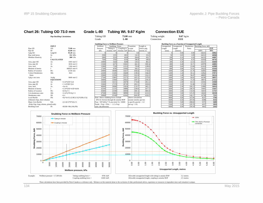
IRP 15 Snubbing Operations Appendix J: Pipe Buckling Forces – Petro-Canada
134 May 2015
Pipe Buckling Calculations Tubing OD 73.00 mm Tubing weight 9.67 kg/m
Grade L-80 Connection EUE
Snubbing Force vs Wellbore Pressure Buckling Force as a Function of Unsupported Length
INPUT Wellbore Snubbing Force Transition Length at Unsupported Unsupported Slenderness Buckling Force, daN
Pipe OD OD 73.00 mm Pressure Tubing in Coupling in to pipe which cplg. Length Length Ratio EUE
Pipe ID ID 62.00 mm kPa Annular, daN Annular, daN heavy, m. neutral, m. (mm) (metres) 100% 70%
Cplg OD CplgOD 93.20 mm 0 0 0 0.0 0.0 0 0.00 0.00 64231 44962
Pipe yield stress Sy 551 MPa 2500 1255 2052 132.3 216.3 50 0.05 2.09 64212 44948
Modulus Elasticity E 200 GPa 5000 2510 4104 264.6 432.7 100 0.10 4.18 64153 44907
CALCULATED 7500 3765 6156 396.9 649.0 200 0.20 8.35 63918 44743
Area, pipe OD Ao 4183 mm^2 10000 5020 8208 529.2 865.3 300 0.30 12.53 63527 44469
Area, pipe ID Ai 3018 mm^2 12500 6275 10261 661.5 1081.6 400 0.40 16.71 62979 44085
Area, steel As 1166 mm^2 15000 7530 12313 793.8 1298.0 600 0.60 25.06 61414 42990
Moment of Inertia I 668325 mm^4 17500 8785 14365 926.1 1514.3 800 0.80 33.41 59223 41456
Radius of Gyration RG 23.94 mm 20000 10040 16417 1058.4 1730.6 1000 1.00 41.76 56405 39484
Critical Slenderness SRc 84.6 22500 11295 18469 1190.6 1946.9 1200 1.20 50.12 52962 37073
Ratio 25000 12550 20521 1322.9 2163.3 1400 1.40 58.47 48892 34224
Cplg x-sect area Acplg 6840 mm^2 27500 13805 22573 1455.2 2379.6 1600 1.60 66.82 44196 30937
EQUATIONS 30000 15060 24625 1587.5 2595.9 1800 1.80 75.18 38874 27212
Area, pipe OD Ao =3.14*(OD^2)/4 32500 16315 26678 1719.8 2812.2 2000 2.00 83.53 32926 23048
Area, pipe ID Ai = 3.14*(ID^2)/4 35000 17570 28730 1852.1 3028.6 2200 2.20 91.88 27229 19060
Area, steel As =Ao-Ai 40000 20080 32834 2116.7 3461.2 2400 2.40 100.23 22880 16016
Moment of Inertia I =3.14*(OD^4-ID^4)/64 42500 21335 34886 2249.0 3677.5 2600 2.60 108.59 19495 13647
Radius of Gyration RG =(I/As)^.5 45000 22590 36938 2381.3 3893.9 2800 2.80 116.94 16810 11767
Crit.slenderness ratio SRc =3.14*(2*E/Sy)^.5 47500 23845 38990 2513.6 4110.2 3000 3.00 125.29 14643 10250
Slenderness ratio SR =L/r 50000 25100 41042 2645.9 4326.5 3500 3.50 146.17 10758 7531
Local Buckle Flb =Sy*As*(1-(L/RG)^2/(2*(SRc)^2)) Note: Above snubbing forces include Above calculations 4000 4.00 167.06 8237 5766
(Johnson's Eqn, short column) 20% for friction through the annular BOP assume annulus gas has 4500 4.50 187.94 6508 4556
Major Axis Buckle Feb =(3.14)^2*E*I/(L)^2 Fwp = WP (kPa) * X-area (mm^2) / 10000 a specific gravity = 1.0 5000 5.00 208.82 5272 3690
(Euler Eqn, long column, pinned ends) Fsnub = Fwp + Ffric = 1.2 x Fwp (air sg = 1.0) 5500 5.50 229.70 4357 3050
Buckling Load Fb =IF(SR>SRc,Feb,Flb) units: decaNewtons 6000 6.00 250.59 3661 2563
Example: Wellbore pressure = 17,500 kPa Tubing snubbing force = 8785 daN Allowable unsupported length with tubing in annular BOP 3.2 metres
Coupling snubbing force = 14365 daN Allowable unsupported length, coupling in annular BOP 2.5 metres
These calculations have been provided by Petro-Canada as a reference only. Reliance on this material alone to the exclusion of other professional advice, experience or resources is imprudent since each situation is unique.
Buckling Force vs. Unsupported Length
0
10000
20000
30000
40000
50000
60000
70000
0.0
0
0.5
0
1.0
0
1.5
0
2.0
0
2.5
0
3.0
0
3.5
0
4.0
0
4.5
0
5.0
0
5.5
0
6.0
0
Unsupported Length, metres
B
ucklin
g F
orc
e, d
aN
100%
70%, EUE or Premiumconnection
Snubbing Force vs Wellbore Pressure
0
10000
20000
30000
40000
50000
60000
70000
0
50
00
10
00
0
15
00
0
20
00
0
25
00
0
30
00
0
35
00
0
40
00
0
45
00
0
50
00
0
Wellbore pressure, kPa
Sn
ub
bin
g F
orc
e, d
aN
Tubing in Annular
Coupling in Annular
Chart 26: Tubing OD 73.0 mm Grade L-80 Tubing Wt. 9.67 Kg/m Connection EUE

May 2015
135
Pipe Buckling Calculations Tubing OD 88.90 mm Tubing weight 13.84 kg/m
Grade J-55 Connection EUE
Snubbing Force vs Wellbore Pressure Buckling Force as a Function of Unsupported Length
INPUT Wellbore Snubbing Force Transition Length at Unsupported Unsupported Slenderness Buckling Force, daN
Pipe OD OD 88.90 mm Pressure Tubing in Coupling in to pipe which cplg. Length Length Ratio EUE
Pipe ID ID 76.00 mm kPa Annular, daN Annular, daN heavy, m. neutral, m. (mm) (metres) 100% 70%
Cplg OD CplgOD 114.30 mm 0 0 0 0.0 0.0 0 0.00 0.00 63288 44301
Pipe yield stress Sy 379 MPa 2500 1861 3086 137.1 227.3 50 0.05 1.71 63279 44295
Modulus Elasticity E 200 GPa 5000 3722 6173 274.2 454.7 100 0.10 3.42 63252 44276
CALCULATED 7500 5584 9259 411.3 682.0 200 0.20 6.84 63145 44202
Area, pipe OD Ao 6204 mm^2 10000 7445 12346 548.3 909.3 300 0.30 10.26 62968 44077
Area, pipe ID Ai 4534 mm^2 12500 9306 15432 685.4 1136.7 400 0.40 13.68 62719 43903
Area, steel As 1670 mm^2 15000 11167 18519 822.5 1364.0 600 0.60 20.52 62007 43405
Moment of Inertia I 1427648 mm^4 17500 13028 21605 959.6 1591.3 800 0.80 27.36 61011 42708
Radius of Gyration RG 29.24 mm 20000 14890 24692 1096.7 1818.7 1000 1.00 34.20 59731 41812
Critical Slenderness SRc 102.0 22500 16751 27778 1233.8 2046.0 1200 1.20 41.04 58166 40716
Ratio 25000 18612 30865 1370.8 2273.3 1400 1.40 47.88 56316 39421
Cplg x-sect area Acplg 10288 mm^2 27500 20473 33951 1507.9 2500.6 1600 1.60 54.72 54182 37927
EQUATIONS 30000 22334 37038 1645.0 2728.0 1800 1.80 61.56 51763 36234
Area, pipe OD Ao =3.14*(OD^2)/4 32500 24196 40124 1782.1 2955.3 2000 2.00 68.40 49060 34342
Area, pipe ID Ai = 3.14*(ID^2)/4 35000 26057 43211 1919.2 3182.6 2200 2.20 75.24 46072 32251
Area, steel As =Ao-Ai 40000 29779 49384 2193.4 3637.3 2400 2.40 82.08 42800 29960
Moment of Inertia I =3.14*(OD^4-ID^4)/64 42500 31641 52470 2330.4 3864.6 2600 2.60 88.92 39243 27470
Radius of Gyration RG =(I/As)^.5 45000 33502 55557 2467.5 4092.0 2800 2.80 95.76 35402 24781
Crit.slenderness ratio SRc =3.14*(2*E/Sy)^.5 47500 35363 58643 2604.6 4319.3 3000 3.00 102.60 31280 21896
Slenderness ratio SR =L/r 50000 37224 61730 2741.7 4546.6 3500 3.50 119.70 22981 16087
Local Buckle Flb =Sy*As*(1-(L/RG)^2/(2*(SRc)^2)) Note: Above snubbing forces include Above calculations 4000 4.00 136.80 17595 12317
(Johnson's Eqn, short column) 20% for friction through the annular BOP assume annulus gas has 4500 4.50 153.90 13902 9732
Major Axis Buckle Feb =(3.14)^2*E*I/(L)^2 Fwp = WP (kPa) * X-area (mm^2) / 10000 a specific gravity = 1.0 5000 5.00 171.00 11261 7883
(Euler Eqn, long column, pinned ends) Fsnub = Fwp + Ffric = 1.2 x Fwp (air sg = 1.0) 5500 5.50 188.10 9306 6515
Buckling Load Fb =IF(SR>SRc,Feb,Flb) units: decaNewtons 6000 6.00 205.20 7820 5474
Example: Wellbore pressure = 17,500 kPa Tubing snubbing force = 13028 daN Allowable unsupported length with tubing in annular BOP 3.8 metres
Coupling snubbing force = 21605 daN Allowable unsupported length, coupling in annular BOP 3.0 metres
These calculations have been provided by Petro-Canada as a reference only. Reliance on this material alone to the exclusion of other professional advice, experience or resources is imprudent since each situation is unique.
Buckling Force vs. Unsupported Length
0
10000
20000
30000
40000
50000
60000
70000
0.0
0
0.5
0
1.0
0
1.5
0
2.0
0
2.5
0
3.0
0
3.5
0
4.0
0
4.5
0
5.0
0
5.5
0
6.0
0
Unsupported Length, metres
B
ucklin
g F
orc
e, d
aN
100%
70%, EUE or Premiumconnection
Snubbing Force vs Wellbore Pressure
0
10000
20000
30000
40000
50000
60000
70000
0
50
00
10
00
0
15
00
0
20
00
0
25
00
0
30
00
0
35
00
0
40
00
0
45
00
0
50
00
0
Wellbore pressure, kPa
Sn
ub
bin
g F
orc
e, d
aN
Tubing in Annular
Coupling in Annular
Chart 27: Tubing OD 88.9 mm Grade J-55 Tubing Wt. 13.84 Kg/m Connection EUE

IRP 15 Snubbing Operations Appendix J: Pipe Buckling Forces – Petro-Canada
136 May 2015
Pipe Buckling Calculations Tubing OD 88.90 mm Tubing weight 13.84 kg/m
Grade L-80 Connection EUE
Snubbing Force vs Wellbore Pressure Buckling Force as a Function of Unsupported Length
INPUT Wellbore Snubbing Force Transition Length at Unsupported Unsupported Slenderness Buckling Force, daN
Pipe OD OD 88.90 mm Pressure Tubing in Coupling in to pipe which cplg. Length Length Ratio EUE
Pipe ID ID 76.00 mm kPa Annular, daN Annular, daN heavy, m. neutral, m. (mm) (metres) 100% 70%
Cplg OD CplgOD 114.30 mm 0 0 0 0.0 0.0 0 0.00 0.00 92009 64406
Pipe yield stress Sy 551 MPa 2500 1861 3086 137.1 227.3 50 0.05 1.71 91990 64393
Modulus Elasticity E 200 GPa 5000 3722 6173 274.2 454.7 100 0.10 3.42 91934 64354
CALCULATED 7500 5584 9259 411.3 682.0 200 0.20 6.84 91709 64196
Area, pipe OD Ao 6204 mm^2 10000 7445 12346 548.3 909.3 300 0.30 10.26 91333 63933
Area, pipe ID Ai 4534 mm^2 12500 9306 15432 685.4 1136.7 400 0.40 13.68 90806 63564
Area, steel As 1670 mm^2 15000 11167 18519 822.5 1364.0 600 0.60 20.52 89303 62512
Moment of Inertia I 1427648 mm^4 17500 13028 21605 959.6 1591.3 800 0.80 27.36 87198 61039
Radius of Gyration RG 29.24 mm 20000 14890 24692 1096.7 1818.7 1000 1.00 34.20 84491 59144
Critical Slenderness SRc 84.6 22500 16751 27778 1233.8 2046.0 1200 1.20 41.04 81184 56829
Ratio 25000 18612 30865 1370.8 2273.3 1400 1.40 47.88 77274 54092
Cplg x-sect area Acplg 10288 mm^2 27500 20473 33951 1507.9 2500.6 1600 1.60 54.72 72764 50935
EQUATIONS 30000 22334 37038 1645.0 2728.0 1800 1.80 61.56 67651 47356
Area, pipe OD Ao =3.14*(OD^2)/4 32500 24196 40124 1782.1 2955.3 2000 2.00 68.40 61938 43357
Area, pipe ID Ai = 3.14*(ID^2)/4 35000 26057 43211 1919.2 3182.6 2200 2.20 75.24 55623 38936
Area, steel As =Ao-Ai 40000 29779 49384 2193.4 3637.3 2400 2.40 82.08 48707 34095
Moment of Inertia I =3.14*(OD^4-ID^4)/64 42500 31641 52470 2330.4 3864.6 2600 2.60 88.92 41645 29152
Radius of Gyration RG =(I/As)^.5 45000 33502 55557 2467.5 4092.0 2800 2.80 95.76 35908 25136
Crit.slenderness ratio SRc =3.14*(2*E/Sy)^.5 47500 35363 58643 2604.6 4319.3 3000 3.00 102.60 31280 21896
Slenderness ratio SR =L/r 50000 37224 61730 2741.7 4546.6 3500 3.50 119.70 22981 16087
Local Buckle Flb =Sy*As*(1-(L/RG)^2/(2*(SRc)^2)) Note: Above snubbing forces include Above calculations 4000 4.00 136.80 17595 12317
(Johnson's Eqn, short column) 20% for friction through the annular BOP assume annulus gas has 4500 4.50 153.90 13902 9732
Major Axis Buckle Feb =(3.14)^2*E*I/(L)^2 Fwp = WP (kPa) * X-area (mm^2) / 10000 a specific gravity = 1.0 5000 5.00 171.00 11261 7883
(Euler Eqn, long column, pinned ends) Fsnub = Fwp + Ffric = 1.2 x Fwp (air sg = 1.0) 5500 5.50 188.10 9306 6515
Buckling Load Fb =IF(SR>SRc,Feb,Flb) units: decaNewtons 6000 6.00 205.20 7820 5474
Example: Wellbore pressure = 17,500 kPa Tubing snubbing force = 13028 daN Allowable unsupported length with tubing in annular BOP 3.8 metres
Coupling snubbing force = 21605 daN Allowable unsupported length, coupling in annular BOP 3.0 metres
These calculations have been provided by Petro-Canada as a reference only. Reliance on this material alone to the exclusion of other professional advice, experience or resources is imprudent since each situation is unique.
Buckling Force vs. Unsupported Length
0
10000
20000
30000
40000
50000
60000
70000
80000
90000
100000
0.0
0
0.5
0
1.0
0
1.5
0
2.0
0
2.5
0
3.0
0
3.5
0
4.0
0
4.5
0
5.0
0
5.5
0
6.0
0
Unsupported Length, metres
B
ucklin
g F
orc
e, d
aN
100%
70%, EUE or Premiumconnection
Snubbing Force vs Wellbore Pressure
0
10000
20000
30000
40000
50000
60000
70000
80000
90000
100000
0
50
00
10
00
0
15
00
0
20
00
0
25
00
0
30
00
0
35
00
0
40
00
0
45
00
0
50
00
0
Wellbore pressure, kPa
Sn
ub
bin
g F
orc
e, d
aN
Tubing in Annular
Coupling in Annular
Chart 28: Tubing OD 88.9 mm Grade L-80 Tubing Wt. 13.84 Kg/m Connection EUE

Appendix K: Tubing Plug and Burst Disc Recommendations IRP 15 Snubbing Operations
May 2015
137
Appendix K: Tubing Plug and Burst Disc Recommendations
X – Single Burst Disc XX – Two Burst Discs
Tubing end plug
Single locking plug & slip
stop
Single permanent
plug
Dual locking plugs & slip
stop
Dual permanent
plugs
Dual float assembly
Down hole shutoff valve
(1/4 turn)
Regular burst disc &
Combination burst disc
(10k or 15k)
Sweet, less than 14 MPA differential
X X X X X X
Sour, greater than 14 MPA differential and less than 500 ppm H2S
X X X X X
Sweet, between 14 – 21 MPA differential
X X X X X X
Sour, between 14-21 MPA differential and less than 500 ppm H2S
X X X X X
Pre-Spud sign off required on all scenarios below
Sour, less than 21 MPA differential, greater than 500 ppm H2S
X X X X XX*
Sweet, greater than 21 MPA differential
X X X X XX*
Sour, greater than 21 MPA differential, less than 500 ppm H2S
X X X X XX*
Sour, greater than 21 MPA differential, greater than 500 ppm H2S
X X X X XX*
*Recommended distance between two plugs for dual barrier: 3-10m. When tubing fill is required and the ability to obtain <21MPa across a single barrier is not possible, the burst disc should be set as the lower barrier and a pump through plug as the second, upper barrier.

138 May 2015
Burst Discs
When receiving, handling, transporting and running burst discs of any size and style
(single or dual barrier) the following minimum recommendations should be applied:
1. Compliance letter (i.e. manufacturing, seal specifications (sour service, temp rates, etc.) shall accompany each burst disc.
2. Individual Identification such as a serial # stamped on the body. This insures that the test chart and all other relevant paper work are fully traceable to the individual burst disc body.
3. Each burst disc must be individually pressure tested (not less than 10 minutes) and real time charted. The test charts must be available upon request to the Oil/Gas Company and/or the Snubbing personnel.
4. Safe Trip Packaging: All burst discs must be safe trip packaged for pickup and delivery to the customer. Such packaging must have proof of its ability to protect the burst discs in day to day handling and transportation.
5. Transportation: While transporting the burst disc from the supplier to the end user the transport company should follow proper load securement protocol.
6. OEM specifications should be followed when making up a burst disc into a BHA. DO NO APPLY TORQUE THROUGH THE BODY OF THE BURST DISC.
7. If tubing bill is required to displace oxygen or to prevent collapse while running in hole, dual burst discs are not recommended as the hydrostatic pressure may burst the uppermost disc prematurely or the differential across the void between the two burst discs could cause the tubing to collapse.

Acronyms and Abbreviations IRP 15 Snubbing Operations
May 2015
139
Acronyms and Abbreviations
ACGIH American Conference of Governmental Industrial Hygienists
ANSI American National Standards Institute
AOF Absolute Open Flow
API American Petroleum Institute
ASME American Society of Mechanical Engineers
ASTM American Society of Testing and Materials
BHA Bottom hole Assembly
BOP Blowout Preventer
CAODC Canadian Association of Oil well Drilling Contractors
CAPP Canadian Association of Petroleum Producers
CF Cubic Feet
COR Certificate of Recognition
CSA Canadian Standards Association
DACC Drilling and Completions Committee
DOT Department of Transportation
ERP Emergency Response Plan
ESD Emergency Shutdown Valve
EUE External Upset End.
GL Ground Level
GODI General Oilfield Driver Improvement
H2S Hydrogen Sulphide.
ID Inside Diameter
IRP Industry Recommended Practice
JSA Job Safety Analysis
KB Kelly Bushing
MPI Magnetic Particle Inspection
NACE National Association of Corrosion Engineers
OD Outside Diameter
OEM Original Equipment Manufacturer
OSHA Occupational Safety and Health Administration
PBTD Plug Back Total Depth

IRP 15 Snubbing Operations Acronyms and Abbreviations
140 May 2015
PCP Petroleum Competency Program
PHRCC Petroleum Human Resources Council of Canada
PPE Personal Protective Equipment
PR Type of Plug
PRN Type of Plug
PSAC Petroleum Services Association of Canada
PX Type of Plug
PXN Type of Plug
RP Recommended Practice
SABA Supplied Air Breathing Apparatus (a type of respiratory equipment)
SCBA Self-Contained Breathing Apparatus (a type of respiratory protective equipment)
SEPAC Small Explorers and Producers Association of Canada
SICP Shut-In Casing Pressure
SITP Shut-In Tubing Pressure
STARS Shock Trauma Air Rescue Society
TD Total Depth
TDG Transportation of Dangerous Goods
TKX Type of Plug
TKXN Type of Plug
TLV Threshold Limit Value
TX Type of Plug
TXN Type of Plug
WCB Workers’ Compensation Board

Glossary IRP 15 Snubbing Operations
May 2015
141
Glossary
Accumulator A small tank or pressure vessel to hold air, gas, or liquid under
pressure for use in a hydraulic or air-actuated system; stores a source of pressure for use at a regulated rate in mechanisms or equipment in a plant or in drilling or production operations; can also be a vessel or tank that receives and temporarily stores a liquid used in a continuous process in a gas plant.
Annular preventer A device which can seal around any object in the borehole or upon itself; compression of a reinforced elastomer packing element by hydraulic pressure causes the seal.
Balance Point The point when the weight of the pipe equals the forces created by the well pressure acting on the cross-sectional area of the pipe; also known as the transition point or snub point.
Bleeding off To equalize or relieve pressure from a vessel or system.
Bleed-off The section of manifold containing the valves and piping necessary to bleed off pressure from a vessel or system; bleed-off lines may be exposed to widely fluctuating pressures, must be adequately secured, and consideration must be given to safe handling or disposal of resulting fluids.
Blowout preventer A large valve at the top of a well that may be closed if there is loss of control of formation gas/fluids.
Bottomhole assembly Tools deployed on the tubing, usually at the bottom
of the string.
Bridge plug A down hole tool located and set to isolate the lower part of the wellbore; may be permanent or retrievable, enabling the lower wellbore to be permanently sealed from production or temporarily isolated from a treatment conducted on an upper zone.
Buckling load The load that will cause a distortion, bend, or kink in the pipe.
Catwalk A platform used as a staging area for rig and drill string tools,
components that are about to be picked up and run, or components that have been run and are being laid down.
Cavitating Pulsating movement.
Certificate (for equipment) A document with an engineer’s stamp.
Chiksan A type of swivel joint.
Choke A device with an orifice used to control fluid flow rate or downstream system pressure.
Classification See well classification.

IRP 15 Snubbing Operations Glossary
142 May 2015
Coiled tubing A jointless hollow steel cylinder that can be uncoiled or coiled as required; used in well completion and servicing instead of traditional tubing (joined sections of pipe).
Collar A threaded coupling used to join two lengths of pipe such as production tubing or casing.
Competency See worker competency.
Condensate The liquid hydrocarbons produced with natural gas that are separated from the gas by cooling and various other means; the liquid recovery from a well classified as a gas well; generally in the gaseous state under reservoir conditions but becomes liquid either in passing up the hole or at the surface.
Contingency procedure A procedure for an unforeseen event, incident, or emergency.
Coupling A connection device for fastening two lengths of tubing.
Critical sour well Defined by jurisdiction’s regulatory agency; generally
includes all the elements of a sour well plus the added concerns of residents near the well site and environmental issues.
Crown saver An upward limiting device for traveling assembly on rig;
prevents the blocks from striking the crown.
Designation See well designation.
Detent The function of a hydraulic control that maintains it in the open or closed position.
Division See well division.
Elastomer Often used interchangeably with the term “rubber”; primary uses are for seals, adhesives and molded flexible parts.
Equalizing prong Part of tubing plug.
External upset end An extra thick wall at the threaded end of drill pipe or tubing; does not have a uniform OD throughout its length but is enlarged at each end.
Expansion joint A device or completion component designed to enable relative movement between two fixed assemblies in the event of thermal expansion or contraction; expansion joints within the completion assembly prevent any movement or forces being transmitted to fixed components such as packers or tubing hangers.
Explosive mixture A gas and air mixture that will form an ignitable mixture.
Explosive potential Any time there is an explosive mixture present with a potential source of ignition.
Fishing The application of tools, equipment, and techniques for the removal of tools, casing, or other items lost or stuck in a wellbore; key elements of fishing include an understanding of the dimensions and nature of the items to be removed, the wellbore conditions, the tools and techniques employed, and the process by which the recovered items will be handled at surface.

Glossary IRP 15 Snubbing Operations
May 2015
143
Fishneck The groove in the top of many wireline tools to allow other tools to clamp the tool and remove it from the wellbore.
Fluid spacer A column of fluid in wellbore, usually above a tubing plug.
Frac oil Oil injected into a well in a fracturing operation which may then be recovered through production.
Fracing (Fracturing) A stimulation treatment routinely performed on oil and gas wells in low-permeability reservoirs; process of pumping into a closed wellbore with powerful hydraulic pumps to create enough down hole pressure to crack or fracture the formation.
Frictional force The force for passing through BOPs.
G pack-off A retrievable non-profile setting plug.
Gravitational force The force from the weight of the string.
Grounding Conducting electricity harmlessly into the ground in case of a fault.
Hang-off flange A sealed flange used to support a string of tubing or drill
pipe; prevents movement.
Hook-wall plug A retrievable non-profile setting plug.
Hydrates Compounds in which natural gas molecules are trapped within a
crystal structure; form in cold climates, such as permafrost zones and deep water; can form in pipelines and in gas gathering, compression, and transmission facilities at reduced temperatures and high pressures.
Hydraulic snubbing unit The most widely used snubbing unit; sometimes called hydraulic work over unit; hydraulic pressures act on cylinders to produce a force that is transmitted to the work string so the snubbing unit performs the operation of pushing pipe into or pulling pipe from a pressurized well; traveling slips transmit the lifting or snubbing force from jack to pipe.
Hydrogen sulphide A gaseous compound, commonly known by its chemical formula, H2S; frequently found in oil and gas reservoirs; has a distinctive rotten egg odor at low parts per million; is extremely poisonous and corrosive and quickly deadens the olfactory nerve so that its odor is no longer a warning signal.
Interlock system A device that physically prevents activation of the system used for controlling the operation of machinery or equipment.
Iron sulphide A compound containing iron and sulphur; examples are ferric
sulphide, ferrous sulphide, and iron disulphide.
Jack Hydraulic cylinders used to provide the force to move the pipe up or down.
Jar (Jarring device) A down hole tool used to deliver a heavy blow or impact to a down hole tool assembly or tool string; commonly used to operate down hole tools, to dislodge a stuck tool string, or in fishing to free stuck objects.

IRP 15 Snubbing Operations Glossary
144 May 2015
Joint safety meeting A safety meeting coordinated by well site supervisor with the multiple contractors on location.
Kelly bushing A device fitted to the rotary table through which the kelly passes and by means of which the torque of the rotary table is transmitted to the kelly and to the drill stem; sometimes called drive bushing.
KCl water Potassium chloride water; a non-invasive kill fluid.
Kill fluid Mud whose density is high enough to produce a hydrostatic pressure at the point of influx in a wellbore and shut off flow into the well.
Kill lines High-pressure pipe leading from an outlet on the BOP stack to the high-pressure rig pumps.
Lift force gauge A gauge that measures hydraulic pressure required to lift a string of tubing.
Load plate The interface between snubbing jack structure and snubbing BOP stack.
Lock mandrel – component of down hole plug or profile setting plug.
Lock-out system The system used to prevent the powering or operating of equipment inadvertently or by mistake until locks or tags are removed by the authorized person; also called tag-out.
Lubricating Running tools (packers, sleeves, etc.) into or pulling tools out of a pressurized wellbore while maintaining a seal with a lubricator and pack-off head.
Marker joint A joint of tubing that serves as a position or depth indicator; in most cases, significantly shorter than other joints in the string so that it is easily noticeable on correlation logs or when retrieving a work string. (from Schlumberger)
Metallurgy The science and technology of a metal.
Monkey board A tubular racking board.
Mud can Equipment used to contain fluids and direct them away from the drill pipe when breaking connections.
ND tested Non-destructive tested.
Neutral point The point on a string of tubulars at which there are neither tension nor compression forces present.
New worker An employee with little or no snubbing experience.
No-go locking plug A type of down hole plug; cannot be passed through.
No-go profile A type of a down hole profile; used with no-go locking plug.
One-man tight Tightened by one worker only.
Operating pressure The actual pressure to which a particular system or system component is subjected during normal operations.
Out of spec No longer meeting OEM specifications.

Glossary IRP 15 Snubbing Operations
May 2015
145
Packer A down hole device used to isolate the annulus from the production conduit, enabling controlled production, injection, or treatment; usually incorporates a means of securing the packer against the casing, such as a slip arrangement, and a means of creating a reliable hydraulic seal to isolate the annulus, typically by means of an expandable elastomeric element.
Pancake flange A blanking flange used to prevent flow.
Perforation A tunnel created from the casing into the reservoir formation, through which oil or gas is produced.
Pick-up elevators A hoisting device used to handle a single joint of tubing.
Pick-up nubbin A rigging attachment used to attach snubbing unit pick-up sling to rig elevators.
Pipe heavy See stripping.
Pipe light See snubbing.
Pipe dope A specially formulated blend of lubricating grease and fine metallic particles that prevents metal damage and seals the roots of threads; applied to tool joints when a connection is made.
Pipe ram The closing and sealing component on a BOP whose end is contoured to seal around pipe to close the annular space.
Pipe-drag force The force from pipe drag on the casing in directional, slant, or dog-legged wells.
Plug valve A type of quick-opening valve constructed with a central core or plug; can be opened or closed with one quarter turn of the plug.
Power pack The assembly of components and controls necessary to provide a hydraulic power supply.
Power tong Pneumatically or hydraulically operated tools that serve to spin
the pipe up tight, and in some instances, to apply final make-up torque.
Pressure-area force The force from well pressure acting on the maximum cross-section of the tubing string.
Primary BOP The main blowout preventer in well servicing or drilling operation.
Prime contractor (Primary contractor) The directing contractor for a multi-employer workplace.
Prime mover The source of power for a pump or other device, usually gas engines or electric motors.
Profile brush A wireline tool used to clean profile nipple before plug
installation.
Profile nipple A device of smaller ID than the tubing string installed in tubing string where wireline-conveyed tools can be seated.
Pup joint A joint of tubular shorter than standard length.
Purging The practice where a vessel, container, or piping system is evacuated of its gas and/or fluid contents and replaced with another gas

IRP 15 Snubbing Operations Glossary
146 May 2015
and/or fluid; general purpose is to remove explosive and/or flammable gas/fluid from a closed system before opening the system to the atmosphere or before entry to the system by a worker.
Push/pull force The upward or downward force exerted by the mechanical system used to control tubular movement.
Ram The closing and sealing component on a BOP; rams are of three types: blind, pipe, and shear. Pipe rams, when closed, have a configuration such that they seal around the pipe; shear rams cut through drill pipe and then form a seal; blind rams seal on each other with no pipe in the wellbore.
Ram indicator system The system used to indicate whether rams are open or closed.
Ram saver A device used to ensure movement of pipe cannot occur when rams are closed.
Rig-assist The style of snubbing unit that works with a service or drilling rig.
Rigless The style of snubbing unit that is self-contained.
Round-tripping The complete operation of removing string from wellbore and running it back in the hole.
Sand cleanout – process of removing sand or similar fill from a wellbore.
Separator The production equipment used to separate free liquid components of the well production stream from gaseous elements; separation is accomplished principally by gravity, the heavier liquids falling to the bottom and the gas rising to the top; also a process vessel employed to separate liquids of distinctly different physical properties which result in layering or vapor phasing.
Shackles The rigging component used for attaching lifting components.
Shear ram A BOP element with hardened tool steel blades capable of cutting the pipe; normally used as a last resort to regain pressure control of a well that is flowing.
Sheave A pulley; usually refers to either the pulleys permanently mounted on the top of the rig (the crown blocks), or the pulleys used for running wireline tools into the wellbore.
Shut-off valve An automatically operated valve used for isolating a process
component or process system.
Shut-in casing pressure The pressure measurement recorded for the space between the surface casing and the producing casing during a well test shut-in phase.
Shut-in tubing pressure The shut-in pressure measurement recorded for the tubing during a well test shut-in phase.
Slickline Commonly used to differentiate operations performed with single-strand wire or braided lines; a single-strand wireline used to run and retrieve tools and flow-control equipment in oil and gas wells; a thin nonelectric cable used for selective placement and retrieval of wellbore hardware, such as plugs, gauges and valves.
Glossary IRP 15 Snubbing Operations
May 2015
147
Sliding sleeves A completion device that can be operated to provide a flow path between the production conduit and the annulus; incorporate a system of ports that can be opened or closed by a sliding component that is generally controlled and operated by slickline tool string.
Slim hole valve A full-opening safety valve with an OD smaller than the ID
of the casing string.
Slings A flat, wide piece of material used for moving material with a type of hoist, crane, etc.; also a wire rope loop for use in lifting heavy equipment.
Slip A wedge-shaped piece of metal with teeth or other gripping elements used to prevent pipe from slipping down into the wellbore or for otherwise holding the pipe in place; rotary slips fit around the drill pipe and wedge against the master bushing to support the pipe; power slips are pneumatically or hydraulically actuated devices operated by the driller at this station and which dispenses with the manual handling of slips when making a connection.
Slip bowl A load bearing component of a slip design into which the slip die carriers seat to prevent pipe movement.
Slip pressure The hydraulic pressure required to function the slips.
Slip stop A wireline tool used to prevent plug from moving.
SNUB FORCE gauge A gauge that measures hydraulic pressure required to push a string of tubing into the well.
Snubbing The process of running or pulling pipe where the force created by well pressure acting on the cross-sectional area of the pipe is greater than the weight of the pipe; the well pressure is attempting to force the tubing out of the well, and is known as “pipe light” situation.
Snubbing BOP A secondary well control device.
Snubbing force The force applied by the snubbing unit.
Snubbing jack The components of a hydraulic snubbing unit that provide the vertical movement required to run or retrieve the work string; can apply extremely high forces to the tubing string and the wellhead to which they are attached.
Snubbing program A written program prepared by prime contractor—either
job-specific or part of the total well program—of the operations to be followed at the well site during snubbing.
Snub point See balance point.
Sour well A well having an H2S content of 10 ppm or greater; respiratory protective equipment (e.g. SABA, SCBA) must be worn by personnel exposed to this environment.
Spacer spools The auxiliary equipment used to lubricate tool assemblies in or out the well.
Spool A short section of pipe with flanged ends, used to separate and support the various valves in the stack; spools act as spacers for the valves in the BOP.

IRP 15 Snubbing Operations Glossary
148 May 2015
Spool lifting bracket A device used to move spacer spools with a winch.
Spreader bar An overhead lifting component used to facilitate effective hoisting of the snubbing unit.
Spud To start the well drilling process by removing rock, dirt, and other sedimentary material with the drill bit.
Stabbing valve A valve connected to the work string in case the well starts to flow when running or retrieving the string; to protect against tubing plug or backpressure valve failure.
Staging The act of moving pipe connections in or out of the well using of multiple BOPs and an equalize/bleed-off loop.
Standard of competence Written specification by PCP of the knowledge and skills required by a worker to be applied over the range of circumstances demanded by a job.
Stand-up hoists The hoist used to move a snubbing jack from horizontal to vertical position.
Stationary slips The lower sets of slips attached to the jack plate that secures the pipe while the traveling slips are not engaged; include a slip bowl for light pipe (holding the pipe from moving upwards), and a slip bowl for heavy pipe (holding the pipe from moving downwards).
Stimulation The treatment performed to restore or enhance the productivity of a well; see also fracturing.
Strippers The secondary ram preventers used to stage tubing connections through the BOP stack; the inner seals of these BOPs have usually been modified to accept stripper or wear inserts.
Stripping The process of running or pulling pipe where the weight of the
pipe exceeds the forces created by the well pressure acting on the cross-sectional area of the pipe; the pipe will fall into the well, and is known as “pipe heavy” situation; pipe can be stripped into or out of a live well through a pack-off element/flow diverter or additional annular.
Stripping pipe ram A ram-type BOP used to provide primary pressure control in high-pressure snubbing operations; used when the wellhead pressure is higher than the limitations of a stripper bowl.
Substructure The foundation on which the derrick and engines sit; contains space for storage and well control equipment.
Swabbing The process of unloading liquids from production tubing to initiate
flow from the reservoir.
Sweet well A well having H2S content of 10 ppm or less, and having no harmful of toxic substances and no corrosive or erosive agents.
Tailpipe The tubulars and completion components run below a production packer; can provide a facility for plugs and other temporary flow-control devices, improve down hole hydraulic characteristics, and provide a suspension point for down hole gauges and monitoring equipment.
Tong ram – device used for vertical positioning of snubbing tongs.

Glossary IRP 15 Snubbing Operations
May 2015
149
Tongs The large wrenches used for turning to make up or break out drill pipe, casing, tubing and other pipe; variously called casing tongs, rotary tongs, etc., according to the use for which they are designed.
Tool joint A heavy coupling element having coarse, tapered threads and seating shoulders designed to sustain the weight of the drill stem, withstand the strain of repeated makeup and breakout, and provide a leak proof seal; tool joints may be welded to the drill pipe, screwed onto the pipe, or a combination of screwed on and welded.
Tour A work shift of a crew.
Tour sheets A field invoice.
Traveling slips The upper sets of slips attached to the traveling assembly, which moves vertically up and down as the cylinder rods are extended and retracted; grip the pipe to transmit snubbing or lifting force from the jack to the pipe; most snubbing units are equipped with two sets.
Tripping The process of removing the string from the hole and running it
back in again.
Tubing end plug A non-retrievable type of plug installed in end of tubing and expelled into the well cellar.
Tubing hanger A device included in the wellhead hook-up and contained in the tubing head which, by use of a mandrel or slips, suspends and holds the tubing string.
Tubing-drift gauge ring A wireline tool used to confirm ID of the tubing string.
Underbalanced drilling Drilling that allows a well to flow oil, gas, and formation fluids to surface as it is being drilled; differs from conventional/overbalanced drilling where one of the prime considerations is preventing hydrocarbons from flowing during drilling.
Unsecuring Resuming operations after a well has been secured.
V-door An opening at floor level in a side of a derrick or mast; opposite the drawworks and used as an entry to bring in drill pipe, casing, and other tools from the pipe rack.
Well classification The class name given to wells by industry and
regulatory bodies based on their characteristics; includes the terms “sweet” and “sour.”
Well designation The term used in headings in this IRP that encompasses
both well classifications and well designations; also a term used by the PCP referring to their well designations of “sweet,” “sour or sweet,” and “critical sour or sweet,” and upon which this IRP’s well divisions have been built.
Well division The categories assigned to wells for the purpose of this IRP; includes Divisions 1, 2, and 3.
Wellbore effluent A type of gas or fluid discharged from the well.
Well site supervisor A supervisor employed by prime contractor.

IRP 15 Snubbing Operations Glossary
150 May 2015
Wet tripping Also called wet string, wet pipe; act of pulling a string of pipe from a well with ID full of fluid.
Wireline Well-intervention operations conducted using single-strand or multistrand wire or cable for intervention in oil or gas wells.
Wireline lubricator The assembly of pressure-control equipment used on
wireline operations to house the tool string in preparation for running into the well or for retrieval of the tool string on completion of the operation.
Worker competency PCP occupation ladder and standards of competence
for the snubbing services sector, which provide a framework for assessing and certifying a worker’s competence.

References IRP 15 Snubbing Operations
May 2015
151
References
The list of information sources and documents provided below includes any documents
specifically referred to within this IRP and several additional sources that are useful for
reference for basic information on occupational health and safety. Specific snubbing
references will vary from jurisdiction to jurisdiction. This list is not exhaustive and any
web addresses listed are current at the time of publication of this IRP but are subject to
change.
Edition Remarks / Changes
ACGIH
Table 1: Cooling Power of Wind on Exposed Flesh Expressed as Equivalent Temperature, 1998 Threshold Limit Values
Table 2: TLVs Work Warm-Up Schedule for Four Hour Shift (Under Discretion of Supervisor on Site) – 1998 TLVs
www.acgih.org
Government of Alberta | Alberta Energy Regulator www.aer.ca
Government of Alberta | Employment, Immigration and Industry
www.hre.gov.ab.ca
Government of Alberta | Municipal Affairs | Canadian Electrical Code – Electrical Safety Information Bulletin
CEC-10 [rev-7] October 2009 (Referenced in Appendix F)
http://www.municipalaffairs.alberta.ca/documents/ss/STANDATA/electrical/454-CEC-10unsigned.pdf
Workers’ Compensation Board | Alberta www.wcb.ab.ca
EII | Workplace Health and Safety www.hre.gov.ab.ca
British Columbia Oil and Gas Commission www.ogc.gov.bc.ca
CAODC
RP 3.0 Service Rigs Inspection and Certification of Masts
RP 3.0A Service Rigs Inspection and Certification of Substructures, Drawworks, and Carriers
RP 4.0 Service Rigs Overhead Equipment Inspection and Certification
RP 6.0 Drilling Blowout Preventer Inspection and Certification
RP 7.0 Service Rigs Well Servicing Blowout Preventer Inspection and Certification
www.caodc.ca
CAPP
Flammable Environments Guideline, Dec 2004. www.capp.ca
Enform
IRP 2: Completing and Servicing Critical Sour Wells
IRP 4: Well Testing and Fluid Handling
IRP 7: Standards for Well site Supervision of Drilling, Completion and Work overs
Workers Guide to Hand Signals for Directing Vehicles
Lease Lighting Guideline
www.enform.ca
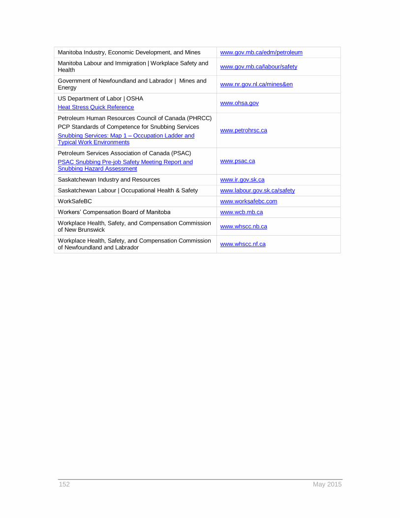
152 May 2015
Manitoba Industry, Economic Development, and Mines www.gov.mb.ca/edm/petroleum
Manitoba Labour and Immigration | Workplace Safety and Health
www.gov.mb.ca/labour/safety
Government of Newfoundland and Labrador | Mines and Energy
www.nr.gov.nl.ca/mines&en
US Department of Labor | OSHA
Heat Stress Quick Reference www.ohsa.gov
Petroleum Human Resources Council of Canada (PHRCC)
PCP Standards of Competence for Snubbing Services
Snubbing Services: Map 1 – Occupation Ladder and Typical Work Environments
www.petrohrsc.ca
Petroleum Services Association of Canada (PSAC)
PSAC Snubbing Pre-job Safety Meeting Report and Snubbing Hazard Assessment
www.psac.ca
Saskatchewan Industry and Resources www.ir.gov.sk.ca
Saskatchewan Labour | Occupational Health & Safety www.labour.gov.sk.ca/safety
WorkSafeBC www.worksafebc.com
Workers’ Compensation Board of Manitoba www.wcb.mb.ca
Workplace Health, Safety, and Compensation Commission of New Brunswick
www.whscc.nb.ca
Workplace Health, Safety, and Compensation Commission of Newfoundland and Labrador
www.whscc.nf.ca

References IRP 15 Snubbing Operations
May 2015
153