Disclosure to Promote the Right To Information Whereas the Parliament of India has set out to provide a practical regime of right to information for citizens to secure access to information under the control of public authorities, in order to promote transparency and accountability in the working of every public authority, and whereas the attached publication of the Bureau of Indian Standards is of particular interest to the public, particularly disadvantaged communities and those engaged in the pursuit of education and knowledge, the attached public safety standard is made available to promote the timely dissemination of this information in an accurate manner to the public. इंटरनेट मानक “!ान $ एक न’ भारत का +नम-ण” Satyanarayan Gangaram Pitroda “Invent a New India Using Knowledge” “प0रा1 को छोड न’ 5 तरफ” Jawaharlal Nehru “Step Out From the Old to the New” “जान1 का अ+धकार, जी1 का अ+धकार” Mazdoor Kisan Shakti Sangathan “The Right to Information, The Right to Live” “!ान एक ऐसा खजाना > जो कभी च0राया नहB जा सकता ह ै” Bhartṛhari—Nītiśatakam “Knowledge is such a treasure which cannot be stolen” IS 11118 (1997): Guidelines for technical evaluation of general purpose parallel lathes [PGD 3: Machine Tools]
Transcript
Disclosure to Promote the Right To Information
Whereas the Parliament of India has set out to provide a practical regime of right to information for citizens to secure access to information under the control of public authorities, in order to promote transparency and accountability in the working of every public authority, and whereas the attached publication of the Bureau of Indian Standards is of particular interest to the public, particularly disadvantaged communities and those engaged in the pursuit of education and knowledge, the attached public safety standard is made available to promote the timely dissemination of this information in an accurate manner to the public.
इंटरनेट मानक
“!ान $ एक न' भारत का +नम-ण”Satyanarayan Gangaram Pitroda
“Invent a New India Using Knowledge”
“प0रा1 को छोड न' 5 तरफ”Jawaharlal Nehru
“Step Out From the Old to the New”
“जान1 का अ+धकार, जी1 का अ+धकार”Mazdoor Kisan Shakti Sangathan
“The Right to Information, The Right to Live”
“!ान एक ऐसा खजाना > जो कभी च0राया नहB जा सकता है”Bhartṛhari—Nītiśatakam
“Knowledge is such a treasure which cannot be stolen”
“Invent a New India Using Knowledge”
है”ह”ह
IS 11118 (1997): Guidelines for technical evaluation ofgeneral purpose parallel lathes [PGD 3: Machine Tools]
IS11118,:1997 ( Superseding IS 12454 : 1988 )
Indian Standard
GUIDELINES FOR TECHNICAL EVALUATION OF GENERAL PURPOSE PARALLEL LATHES
(First Revision )
ICS 25.080.10
0 BIS 1997
BUREAU OF INDIAN STANDARDS Mh~X%MVh~,‘3 BmmSHmZsmmG
NEW DELHI 110002
Febrtrary 1997 Price Group 5
Machine Tools Sectional Committee, PE 03
FOREWORD
This Indian Standard (First Revision) was adopted by the Bureau of Indian Standards, after the draft finalized by the Machine Tools Sectional Committee had been approved by the Production Engineering Division Council.
This standard was first published in 1984 and the present revision also incorporates the requirements laid down in IS 12454 ‘Guidelines for technical evaluation of general purpose parallel lathes with swing over bed above 800 mm’ to make the standard coherent and user friendly. The quality of machine tools has considerably improved during last few years and is now fairly comparable to the high quality machine tools manufactured in industrially advanced countries. Even then there was need to formulate comprehensive standards on machine tool evaluation.
While revising the Indian Standard besides incorporating the requirements laid down in IS 12454, as mentioned earlier the following modifications have been made:
a) the requirements pertaining to lubrication amplified;
b) the requirements pertaining to ‘aesthetics’ deleted;
c) hardness values of guideways suitably modified;
d) despersion indicated in terms of standard deviation in the requirements of repeatability of position; and
e) the requirements pertaining to forced vibration suitably modified.
While revising this standard, considerable assistance has been derived from the publication ‘ Quality and performance evaluation of machine tools’ issued by the Central Machine Tool Institute, Bangalore and data collected from the industry by extensive analysis and testing.
IS 11118 : 1997
Indian Standard
GUIDELINES FOR TECHNICAL EVALUATION OF GENERAL PURPOSE PARALLEL
(First Revision)
1 SCOPE
This standard lays down guidelines for technical evaluation of general purpose parallel lathes.
2 REFERENCES
The following standards contain provision which through reference in this text, constitute provision of this standard. At the time of publication, the editions indicated were valid. All standards are subject to revision, and parties to agreements based on this standard are encouraged to investigate the possibility of applying the most recent editions of the standards indicated below:
IS No. Title
13.56 Electrical equipment of (Partl): 1972 machine tools : Part 1
Electrical equipment of machines for general use ( second revision )
1570 Schedules for wrought steels : ( Part 2/Set 2 ) : 1988 Part 2 Carbon steels
1715 : 1986
1878 ( Part 1 ) : 1993
1878 ( Part 2 ) : 1993
1878 (Part 3 ) : 1996
( unalloyed steels ), Section 2 Carbon steel wires with related properties ( jirst revision )
Dimensions for self holding taper ( second revision )
Test chart for general purpose parallel lathes : Part 1 Lathes with swing over bed up to 800 mm ( second revision )
Test chart for general purpose parallel lathes : Part 2 Lathes withswing over bed over 800 mm and up to 1600 mm ( second revision )
Test chart for general purpose parallel lathes : Part 3 Lathes with swing over bed over 1600 mm up to 2 500 mm (under preparation )
IS No.
2063 : 1988
2092 : 1983
2161 : 1996
2163 : 1976
2182 : 1993
2218 : 1962
2219 : 1962
2428 : 1964
2984 : 1981
2987 : 1992
5706 : 1993
6893 (Part 1) : 1988
8270 (Partl): 1976
LATHES
Title
Acceptance code for machine tools-geometric accuracy of machines operating under noload or finishing conditions (first revision )
Plunger type dial gauges (jkst revision )
Coolant pumps for general purpose machine tools ( first revision )
Carbide tipped single point turning tools (first revision )
Recommendations for symbols to be given on indication plates for machine tools ($rst revision )
Speeds for machine tools
Feeds for machine tools
Application of carbides for machining ranges of application and colour code
Slip gauges ( jrst revision )
Direction of operation of controls for machine tools - Recommendations ( second revision )
Optical instruments - Spirit levels for use in precision engineering (first revision )
Proforma for purchase specification for machine tools: Part 1 Sliding, surfacing and screw cutting lathes
Guide for preparation of diagrams, charts and tables for electrotechnology : Part 1 Definitions and classification
1
IS 11118 : 1997
IS No.
9474 : 1980
9637 : 1980
10573 : 1983
10988 : 1984
11016 : 1984
11133 : 1984
13742 ( Part 1 ) : 1993
Title
Principles of mechanical guarding of machinery
Guidelines for presentation of information in technical manuals
Oil sight glass for machine tools
Method of measuring noise from machine tools (excluding testing in anechoic chambers )
General safety requirements for machine tools and their operation
Recommendations for symbols for lubrication appearing on machine tools
Carbide tipped single point tools - IS0 series : Part 1 Straight turning tools
3 GENERAL CONSIDERATION
3.1 While carrying out tests for evaluation of a machine, reference shall be made to IS 2063, especially for installation of machine before testing, warming up of spindles and other moving parts, description of meauring methods and recommended accuracy of testing equipment.
3.2 The geometrical and practical tests shall be carried out according to IS 1878 (Part 1 to 3 ).
3.3 Speeds and Feeds
The spindle speeds and feeds shall be selected in geometrical series as specified in IS 22 18 and IS 22 19 respectively. From the kinematic scheme, spindle speeds and feed rates shall be calculated. The rated full load motor rpm shall be used for calculation.
The deviation in calculated spindle speeds and feeds shall be within the limits as specified in IS 2218 and IS 22 19 respectively.
NOTE - However, where speeds and feeds are from variable
speed motors, there will be infinitely variable speeds when
feeds are obtained for independent variable speed motors, they
can be infinitely variable.
All the operating levers, such as handles, levers and hand wheels are operated to determine whether their location and the force required to operate them are suitable. The following aspects shall be looked into:
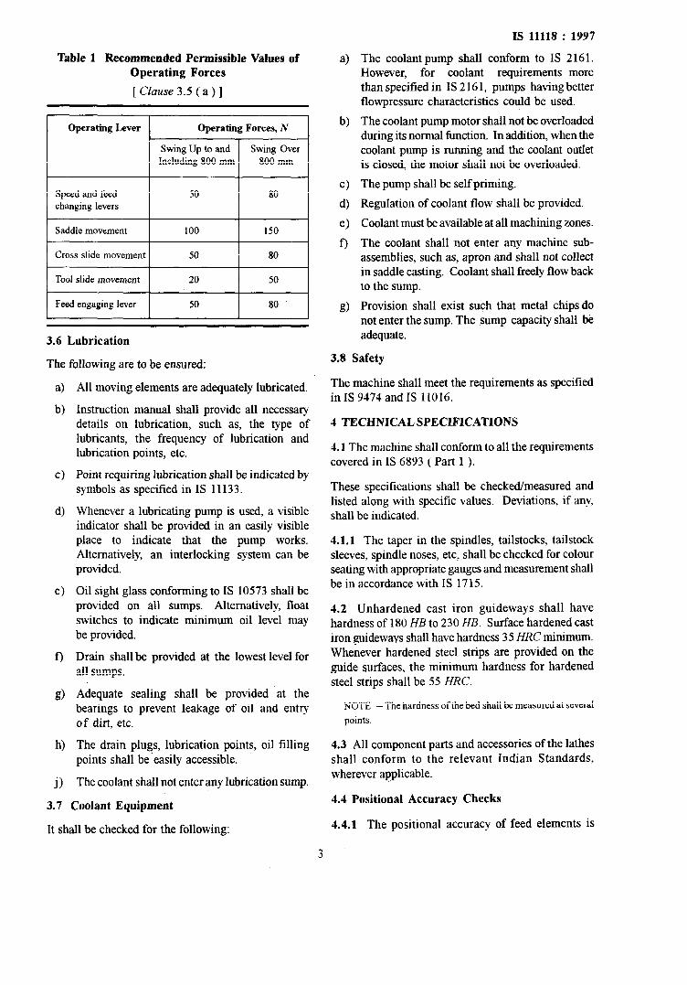
a) The force necessary to be applied depends on the frequency of operation and also the accuracy desirable on the operated part. Recommended permissible values of operating forces shall be as given in Table 1.
b) The location of the operating elements should be convenient for the operator to handle them from his normal place of working. In general, operating elements are recommended to be placed higher than 800 mm and lower than 1200
mm above the floor level.
cl The operating elements shall, in general, correspond to the sequence of movements prescribed in IS 2987.
4 The dimensions and shapes of handles and hand wheels, etc, shall correspond to relevant Indian Standards.
e) The operating elements shall be so located that starting by accidental contacts is not possible. Sufficient space shall be provided to avoid interference between two adjacent levers and even at their extreme positions it shall be convenient to operate them.
f) The operating elements shall not change from the engaged position even under maximum loading of the machine.
g) The indication charts shall be self-explanatory and divisions on hand wheels readable easily. Symbols used on indication plates shall conform to IS 2182.
h) Every operating element is engaged throughout its range and it is checked if the desired function of the operated element is obtained.
8 Wherever interlocking of two functions exists, this has to be checked for its correct functioning.
3.4 Thread Pitches
The thread pitches shall be calculated from the kinematic scheme. The deviation in calculated thread pitches as against the specified thread pitches shall preferably be zero. If any deviation exists, this shall be mentioned in instruction manual.
3.5 Operating Levers
2
Table 1 Recommended Permissible Values of Operating Forces
[ Cluuse 3.5 ( a ) ]
Cross slide movement
3.6 Lubrication
The following are to be ensured:
a> b)
c)
4
e)
f)
g)
h>
j)
All moving elements are adequately lubricated.
Instruction manual shall provide all necessary details on lubrication, such as, the type of lubricants, the frequency of lubrication and lubrication points, etc.
Point requiring lubrication shall be indicated by symbols as specified in IS 1113 3.
Whenever a lubricating pump is used, a visible indicator shall be provided in an easily visible place to indicate that the pump works. Alternatively, an interlocking system can be provided.
Oil sight glass conforming to IS 10573 shall be provided on all sumps. Alternatively, float switches to indicate minimum oil level may be provided.
Drain shall be provided at the lowest level for all sumps.
Adequate sealing shall be provided at the bearings to prevent leakage of oil and entry of dirt, etc.
The coolant pump shall conform to IS 2161. However, for coolant requirements more than specified in IS 2 16 1, pumps having better flowpressure characteristics could be used.
The coolant pump motor shall not be overloaded during its normal function. In addition, when the coolant pump is running and the coolant outlet is closed, the motor shall not be overloaded.
The pump shall be self priming.
Regulation of coolant flow shall be provided.
Coolant must be available at all machining zones.
The coolant shall not enter any machine sub- assemblies, such as, apron and shall not collect in saddle casting. Coolant shall freely flow back to the sump.
Provision shall exist such that metal chips do not enter the sump. The sump capacity shall be adequate.
3.8 Safety
The machine shall meet the requirements as specified in IS 9474 and IS 11016.
4 TECHNICAL SPECIFICATIONS
4.1 The machine shall conform to all the requirements covered in IS 6893 ( Part 1 ).
These specifications shall be checked/measured and listed along with specific values. Deviations, if any, shall be indicated.
4.1.1 The taper in the spindles, tailstocks, tailstock sleeves, spindle noses, etc, shall be checked for colour seating with appropriate gauges and measurement shall be in accordance with IS 1715.
4.2 Unhardened cast iron guideways shall have hardness of 180 HB to 230 HB. Surface hardened cast iron guideways shall have hardness 35 HRC minimum. Whenever hardened steel strips are provided on the guide surfaces. the minimum hardness for hardened steel strips shall be 55 HRC.
NOTE -The hardness ofthe bed shall be measured at several
points.
4.3 All component parts and accessories of the lathes shall conform to the relevant Indian Standards, wherever applicable.
4.4 Positional Accuracy Checks
4.4.1 The positional accuracy of feed elements is
‘7
Is 11118 : 1997
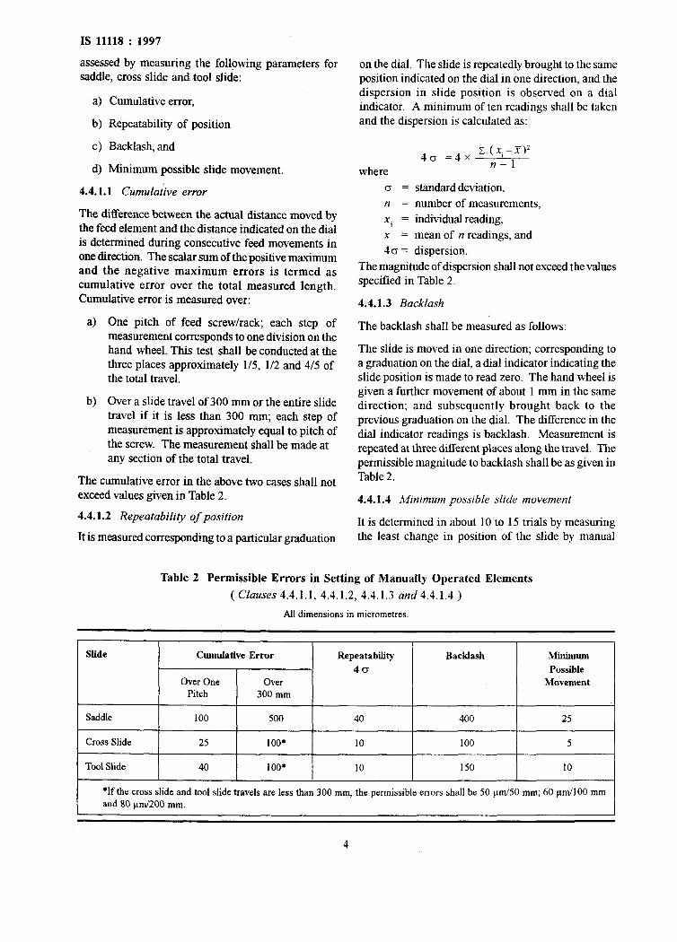
assessed by measuring the following parameters for saddle, cross slide and tool slide:
a) Cumulative error,
b) Repeatability of position
c) Backlash, and
d) Minimum possible slide movement.
4.4.1.1 Cumulative erw-
The difference between the actual distance moved by the feed element and the distance indicated on the dial is determined during consecutive feed movements in one direction. The scalar sum of the positive maximum and the negative maximum errors is termed as cumulative error over the total measured length. Cumulative error is measured over:
a)
b)
One pitch of feed screw/rack; each step of measurement corresponds to one division on the hand wheel. This test shall be conducted at the three places approximately l/S, l/2 and 4/5 of the total travel.
Over a slide travel of 300 mm or the entire slide travel if it is less than 300 mm; each step of measurement is approximately equal to pitch of the screw. The measurement shall be made at any section of the total travel.
The cumulative error in the above two cases shall not exceed values given in Table 2.
4.4.1.2 Repeatability of position
It is measured corresponding to a particular graduation
on the dial. The slide is repeatedly brought to the same position indicated on the dial in one direction, and the dispersion in slide position is observed on a dial indicator. A minimum of ten readings shall be taken and the dispersion is calculated as:
40 =4x c (,K,-w)z
where n-l
0 = standard deviation, n = number of measurements, x. = individual reading, x = mean of n readings, and 4 G = dispersion.
The magnitude of dispersion shall not exceed the values specified in Table 2.
4.4.1.3 Backlash
The backlash shall be measured as follows:
The slide is moved in one direction; corresponding to a graduation on the dial, a dial indicator indicating the slide position is made to read zero. The hand wheel is given a further movement of about 1 mm in the same direction; and subsequently brought back to the previous graduation on the dial. The difference in the dial indicator readings is backlash. Measurement is repeated at three different places along the travel. The permissible magnitude to backlash shall be as given in Table 2.
4.4.1.4 Minimum possible slide movement
It is determined in about 10 to 15 trials by measuring the least change in position of the slide by manual
Table 2 Permissible Errors in Setting of Manually Operated Elements
*If the cross slide and tool slide travels are less than 300 mm, the permissible errors shall be 50 pm/50 mm; 60 pm/100 mm
and 80 pm/ZOO mm.
4
operation. The minimum magnitude of slide movement which can be consistently obtained is decided. The test is repeated in three places along the slide travel, namely, at l/5, l/2 and 4/5 of the total travel. The minimum possible movement is given in Table 2.
4.5 Temperature Rise
Temperature rise on the headstock body shall be measured at a spindle speed which corresponds to a cutting speed of 100 m/min for a workpiece diameter equal to swing/4. The temperature rise shall not exceed 25°C above ambient temperature. The time for stabilization shall be about 1 hour. The time for stabilization is decided as the time at which temperature rise/l5 minute does not exceed 5 percent of the temperature rise above ambient. The spindle shall also be run at the highest spindle speed for about halfan hour. The rise in temperature shall not exceed 25°C above ambient temperature. The temperature of the lubricating oil shall not exceed 65°C.
4.6 Idle Powerloss
This is measured under the following conditions:
a) For swing up to and including 800 mm.
i) At each spindle speed:
ii)
iii)
IS 11118 : 1997
At each spindle speed and at a feed rate equal to swing/l 000 (mm/rev) or 0.5 mm/rev, Max, and
At a spindle speed which corresponds to a cutting speed of 100 m/Min for a workpiece size = swing/4 when each feed rate is engaged [maximum feed rate being swing/l 000 (mm/rev) or 0.5 mm/ rev, Max].
b) For swing over 800 mm:
i) At each spindle speed.
ii) At each spindle speed and at a feed rate equal to ‘swing/2 000 ( mm/rev) or 0.5 mm/rev, Max, and
iii) At a spindle speed which corresponds to a cutting speed of 100 m/min for a workpiece size = swing/4 when each feed rate is engaged [maximum feed rate being swing/2 000 (mm/rev) or 0.5 mm/rev, Max].
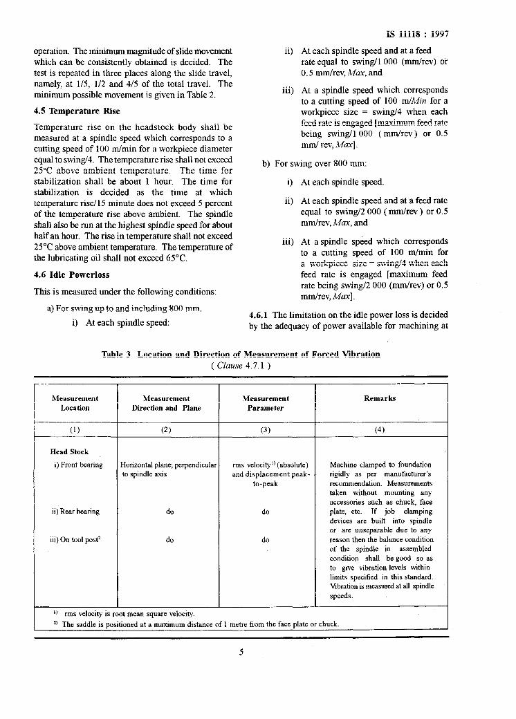
4.6.1 The limitation on the idle power loss is decided by the adequacy of power available for machining at
Table 3 Location and Direction of Measurement of Forced Vibration ( Clause 4.7.1 )
Measurement Measurement Location Direction and Plane
Measurement
Parameter
Remarks
(1) (2) (3) (4)
Head Stock
i) Front bearing
ii) Rear bearing
iii) On tool post*
Horizontal plane; perpendicular to spindle axis
do
do
rms velocity’) (absolute) and displacement peak-
to-peak
do
do
Machine clamped to foundation rigidly as per manufacturer’s recommendation. Measurements taken without mounting any accessories such as chuck, face plate, etc. If job clamping devices are built into spindle or are unseparable due to any reason then the balance condition of the spindle in assembled condition shah be good so as to give vibration levels within limits specified in this standard. Vibration is measured at all spindle speeds.
‘) rms velocity is root mean square velocity.
*) The saddle is positioned at a maximum distance of 1 metre from the face plate or chuck.
5
IS 11118 : 1997
each spindle speed. The idle power loss shall not exceed 30 percent. of motor output taking into account the efficiency of the motor.
4.6.2 Auxiliary motors
In case of any auxiliary motor such as coolant pump motor, etc, it shall be ensured that the motor is not overloaded during its normal function.
4.7 Forced Vibrations
4.7.1 Forced vibrations are measured at all spindle speeds at locations as near to the bearings (front and rear)as possible on the head stock (see Table 3).
4.7.2 Kbration Measuring Equipment
The vibration measurement set up usually consists of a vibration transducer (an accelerometer), an indicator unit which contains an amplifier, correcting filter networks for frequency response, an indicating and/or recording instrument and a power supply system. For vibration severity measurements, the frequency range of instrumentation shall be from 10 to 1 000 Hz.
4.7.3 The forced vibration is specified in terms of amplitude ( peak to peak value ) and frequency of vibration. The velocity of vibration is calculated/ measured as v ( mm/set ) = n: a xf/ 1000.
where
v = velocity of vibration,
a = amplitude of vibration in urn (peak to peak value), and
f = frequency of vibration in Hz.
The permissible magnitude of velocity of vibration ‘v’ is as follows:
Size Range Absolute Mbration Veloci&
(rms) V
mm/s Up to and including
800 mm swing
Over 800 mm swing
4.8 Noise
2.5
4.0
The noise emitted is measured in accordance with IS 10988 : 1984.
4.8.1 The noise level of the machine shall not exceed the following values:
M/C with Swing Noise Level
Up to and including 800 mm SOdD(A)
Over 800 mm 85dD(A)
4.9 Overload Safety Device
The feed drive shall be provided with a safety device such that when the force on the slide exceeds a predetermined magnitude, the drive to the slide gets disconnected. The requirements on the safety device are given below:
4
b) The force at which the overload safety device acts is measured by opposing the slide movement by a moving load. A hydraulic cylinder may be used for the purpose. Spindle speed shall correspond to a cutting speed of 100 m/Min for a workpiece of diameter equal to swing14 and feed rate shall be swing/l 000 and swing/2 000 for m/c with swing upto and including 800 and over 800 mm respctively or 0.5 mm/rev Max in either case. The hydraulic pressure is increased in steps till the overload safety device trips. A dynamo- meter shall be used fortheforce measurement. The force at which the overload safety device trips shall be 100 to 120 percent of the feed force coming on the slide when utilizing full power with a cutting speed of 100 m/Mn.
Example
The disconnection of the drive to the slide shall be instantaneous. This is decided by studying the design of the safety device.
P, x v Power for machining in kW 7 ~
6 120 where
l/ = cutting speed in m/M@ and
P, = tangential cutting force in kgf.
Feed force is taken as 50 percent of the tangential cutting force.
NOTE --. Feed force may be specified by the manufacturer.
4.10 Clamping Forces
4.10.0 The clamping forces shall be measured on tailstock body, tailstock quill and saddle.
4.10.1 Force required to displace the tailstock in the clamped condition shall be 150 percent of the feed force for the m/c with swing over bed upto and including 800 mm and force required to displace the tailstock in the clamped condition shall be 150 percent of the axial job setting force on the tailstock or sum total of axial job setting force and feed force. The feed force is calculated according to 4.9. The’tailstock clamping force is measured by applying a force at the
guideway level. The force is measured on a force dynamometer.
4.10.2 The clamping force on tailstock sleeve shall be 150 percent of the feed force for the m/c with swing over bed above 800 mm and the clamping force on tailstock sleeve together with the axial thrust between tailstock quill nut and screw shall be more than 150 percent of the ax&l job setting force or sum total of axial job setting force and feed force, depending on the direction of feed. This is measured by applying an external force along the sleeve axis. The force is measured on a force dynamometer. During the measurement of clamping force the tailstock feed screw shall be so rotated that the tailstock quill has space to slip in the backlash between the threads for the machine with swing over bed above 800 mm.
4.10.3 The clamping force on saddle shall be 150 percent of the axial force coming on it during facing operation. The magnitude of the axial force is taken equal to the feed force calculated in 4.9. The clamping force is measured by applying an external force at guideways level.
NOTES
1 In all above cases, the clamping bolts are tightened with the
normal leverage available on the corresponding spanner or the
lever supplied by the manufacturer for the purpose. The
magnitude of force applied on the lever shall be measured by
a torque wrench and torque applied shall be indicated.
2 The feed force may be specified by the manufacturer.
4.11 Electrical Test
4.11.1 The design of the circuitry shall be such as to ensure proper sequence, interlocks and other safety measures.
4.11.2 Graphical symbols for electrical elements shall correspond to IS 8270 ( Part 1 ).
4.11.3 The electrical equipments shall meet all the requirements specified in IS 1356 ( Part 1).
4.12 Power Utilization Tests
4.12.1 These tests are carried out by machining two types of workpiece as under:
a) Workpiece held between chuck and live centre; and
b) Workpiece held in chuck only.
4.12.2 The details of workpiece are as given in Fig. 1 and Fig. 2 ( see Annex A).
4.12.3 The cutting tools shall be of carbide tipped parting and turning tools conforming to IS 2163 having
IS 11118 : 1997
cribide tip grade P20 conforming to IS 2428.
4.12.4 Machining is carried out on the workpiece held in chuck and live centre at three places, namely, near head stock, at the middle of workpiece and near the tail stock.
4.12.5 Cutting Conditions
a) Cutting speed 100 mhlin
b) Feed rate up to 0.3 mm/rev for machines with swing over bed up to 500 mm
( For 45O approach Up to 0.5 mm/rev for angle and 90° approach machines with swing over
angle ) bed between 500 and 800 mm
Minimum 0.5 mm/rev for machines with swing over bed above 800 mm and upto 1 600 mm.
Minimum 0.8 mm/rev for machines with swing over bed above 1 600 mm
c) Feed rate for 0.1 to 0.2 mm/rev parting off operation independent of swing
( 0’ approach angle ) over bed
4.12.6 Test Procedure
In case of 45” and 90” approach angle tools, the depth or width of cut shall be gradually increased till full power is utilized or chatter occurs, whichever is earlier. A Wattmeter is connected to the input terminals of the motor. From the motor characteristics, the motor output is calculated from which power utilization is calculated as a percentage of installed capacity. In general, full power utilization is expected for all positions of machining with both the turning tools.
In case of parting off operation ( 0” approach angle tool ) minimum width of cut without chatter shall be more than 0.01 times swing over bed.
4.13 Instructions Manual
An instruction manual shall be provided with each machine to help the customers with ready data on the installation, use and maintenance of the machine. The instruction manual shall comply with all the requirements as laid down in IS 9637.
4.14 Rapid Traverse
Lathes with centre distance 3 m or more shall be provided with a rapid traverse mechanism for carriage and tailstock.
IS 11118 : 1997
4.15 Head Stock Spindle Brake
4.15.1 To reduce the idle time of the machine, the head stock shall be provided with a brake for the lathes with swing over bed above 800 mm. This brake shall apply automatically as soon as the main motor is switched off or power is off.
4.16 Job Length Variation Compensation
4.16.1 To compensate the thermal expansion of job,
tailstock shall be provided witha spring-loaded sleeve. A dial indicating the axial job setting pressure shall be provided for the lathes with swing over bed above 800 mm.
4.17 Equipments Required for Evaluation of the Machine Tools
4.17.1 List of the recommended test equipment and their range has been given in Annex B.
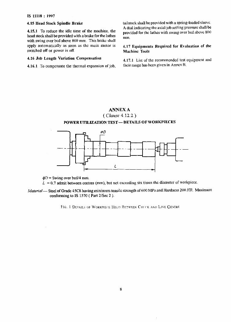
ANNEX A
( Clause 4.12.2 )
POWER UTILIZATION TEST- DETAILS OF WORKPIECES
\
7
Y- --_____ __ --
-L
-
>- 4
#D = Swing over bed/4 mm. L = 0.7 admit between centres (mm), but not exceeding six times the diameter of workpiece.
Material - Steel of Grade 4X8 having minimum tensile strength of 600 MPa and Hardness 200 HB. Maximum conforming to IS 1570 ( Part 2/Set 2 ).
FIG. 1 DE.TA~LS OF WOKKPIIXI: HELD RETLVXN CIIIX.K AND LIVE CENTKE
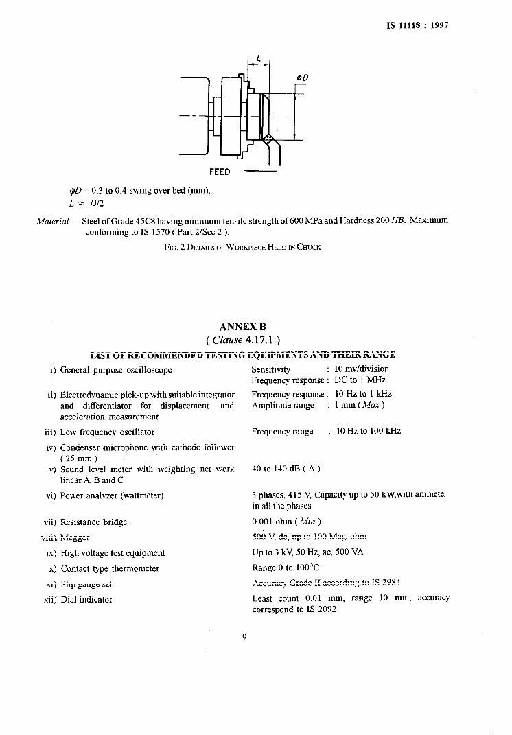
IS 11118 : 1997
FEED -
#D = 0.3 to 0.4 swing over bed (mm).
L = D/2
Material - Steel of Grade 45C8 having minimum tensile strength of 600 MPa and Hardness 200 HB. Maximum conforming to IS 1570 ( Part 2/Set 2 ).
FIG. 2 DETAILS OF WORKPIECE HELD IN CHUCK
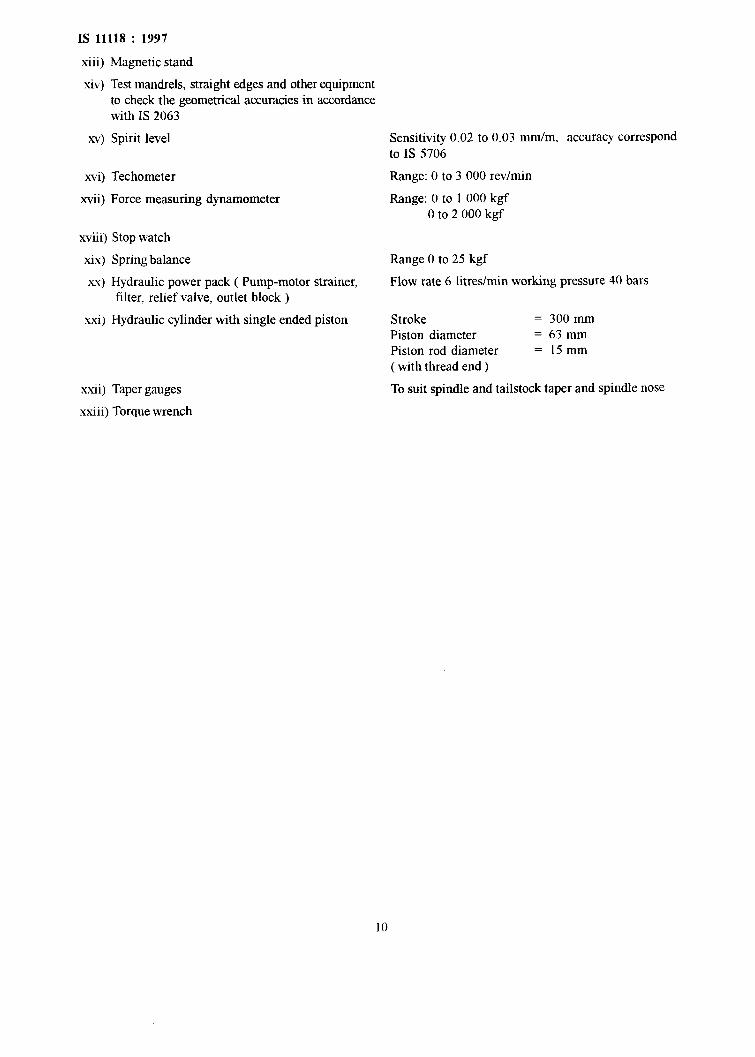
ANNEX B ( Clause 4.17.1 )
LIST OF RECOMMENDED TESTING EQUIPMENTS AND THEIR RANGE
i) General purpose oscilloscope
ii) Electrodynamic pick-up with suitable integrator and differentiator for displacement and acceleration measurement
iii) Low frequency oscillator
iv) Condenser microphone with cathode follower ( 25 mm)
v) Sound level meter with weighting net work linear A, B and C
vi) Power analyzer (wattmeter)
vii) Resistance bridge
viii) Megger
ix) High voltage test equipment
x) Contact type thermometer
xi) Slip gauge set
xii) Dial indicator
Sensitivity : 10 mv/division Frequency response : DC to 1 MHz
Frequency response : 10 Hz to 1 kl-lz Amplitude range : lmm(A4ax)
Frequency range : 10Hzto 1OOkHz
40 to 140 dB ( A)
3 phases, 415 V, Capacity up to 50 kW,with ammete in all the phases
0.001 ohm (Min )
500 V, dc, up to 100 Megaohm
Up to 3 kV, 50 Hz, ac, 500 VA
Range 0 to 1OOOC
Accuracy Grade II according to IS 2984
Least count 0.01 mm, range 10 mm, accuracy correspond to IS 2092
IS 11118 : 1997
xiii) Magnetic stand
xiv) Test mandrels, straight edges and other equipment to check the geometrical accuracies in accordance with IS 2063
Sensitivity 0.02 to 0.03 mm/m, accuracy correspond to IS 5706
Range: 0 to 3 000 rev/min
Range: 0 to 1 000 kgf 0 to 2 000 kgf
Range 0 to 25 kgf
Flow rate 6 litres/min working pressure 40 bars
Stroke = 300 mm Piston diameter = 63mm Piston rod diameter = 15mm ( with thread end )
To suit spindle and tailstock taper and spindle nose
10
Bureau of Indian Standards
BIS is a statutory institution established under the Bureau ofhdian StandardsAct, 1986 to promote harmonious development of the activities of standardization, marking and quality certification of goods and attending to connected matters in the country.
Copyright
BIS has the copyright of all its publications. No part of these publications may be reproduced in any form without the prior permission in writing of BIS. This does not preclude the free use, in the course of implementing the standard, of necessary details, such as symbols and sizes, type or grade designations. Enquiries relating to copyright be addressed to the Director (Publications), BIS.
Review of Indian Standards
Amendments are issued to standards as the need arises on the basis of comments. Standards are also reviewed periodically; a standard along with amendments is reaffirmed when such review indicates that no changes are needed; if the review indicates that changes are needed, it is taken up for revision. Users of Indian Standards should ascertain that they are in possession of the latest amendments or edition by referring to the latest issue of ‘BIS Handbook’ and ‘Standards : Monthly Additions’.
This Indian Standard has been developed from Dot : No. PE 03 ( 124 ).