Disclosure to Promote the Right To Information Whereas the Parliament of India has set out to provide a practical regime of right to information for citizens to secure access to information under the control of public authorities, in order to promote transparency and accountability in the working of every public authority, and whereas the attached publication of the Bureau of Indian Standards is of particular interest to the public, particularly disadvantaged communities and those engaged in the pursuit of education and knowledge, the attached public safety standard is made available to promote the timely dissemination of this information in an accurate manner to the public. इंटरनेट मानक “!ान $ एक न’ भारत का +नम-ण” Satyanarayan Gangaram Pitroda “Invent a New India Using Knowledge” “प0रा1 को छोड न’ 5 तरफ” Jawaharlal Nehru “Step Out From the Old to the New” “जान1 का अ+धकार, जी1 का अ+धकार” Mazdoor Kisan Shakti Sangathan “The Right to Information, The Right to Live” “!ान एक ऐसा खजाना > जो कभी च0राया नहB जा सकता ह ै” Bhartṛhari—Nītiśatakam “Knowledge is such a treasure which cannot be stolen” IS 12235-1 to 19 (2004): Thermoplastics Pipes and Fittings - Methods of Test [CED 50: Plastic Piping System]
Transcript
Disclosure to Promote the Right To Information
Whereas the Parliament of India has set out to provide a practical regime of right to information for citizens to secure access to information under the control of public authorities, in order to promote transparency and accountability in the working of every public authority, and whereas the attached publication of the Bureau of Indian Standards is of particular interest to the public, particularly disadvantaged communities and those engaged in the pursuit of education and knowledge, the attached public safety standard is made available to promote the timely dissemination of this information in an accurate manner to the public.
इंटरनेट मानक
“!ान $ एक न' भारत का +नम-ण”Satyanarayan Gangaram Pitroda
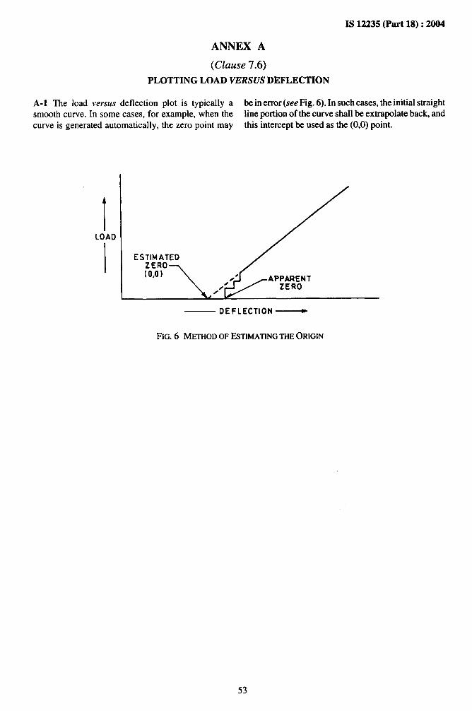
“Invent a New India Using Knowledge”
“प0रा1 को छोड न' 5 तरफ”Jawaharlal Nehru
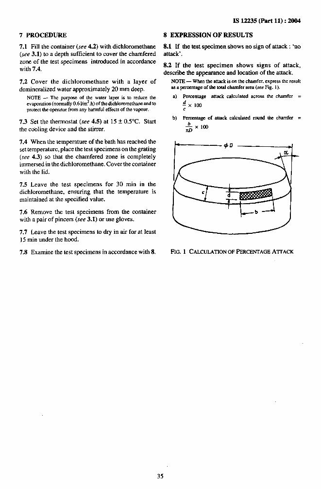
“Step Out From the Old to the New”
“जान1 का अ+धकार, जी1 का अ+धकार”Mazdoor Kisan Shakti Sangathan
“The Right to Information, The Right to Live”
“!ान एक ऐसा खजाना > जो कभी च0राया नहB जा सकता है”Bhartṛhari—Nītiśatakam
“Knowledge is such a treasure which cannot be stolen”
“Invent a New India Using Knowledge”
है”ह”ह
IS 12235-1 to 19 (2004): Thermoplastics Pipes and Fittings- Methods of Test [CED 50: Plastic Piping System]
IS 12235 (Parts 1 to 19) :2004
$777mWFJ7
Y mJ-11%111’wch mndkm-*&*
( Q=n!y”w)
Indian Standard
THERMOPLASTICS PIPES AND FITTINGS —METHODS OF TEST
( First Revision)
ICS 83.080.20,83.140.30,91. 140.60
0 BIS 2004
BUREAU OF IN DIAN STANDARDSMANAK BHAVAN, 9 BAHADUR SHAH ZAFAR MARG
NEW DELHI 110002
October 2004 Price Group 14
Plastics Piping Systems Sectional Committee, CED 50
FOREWORD
This Indian Standard (Parts 1 to 19) (First Revision) was adopted by the Bureau of Indian Standards, after thedraft finalized by the Plastics Piping Systems Sectional Committee had been approved by the Civil EngineeringDivision Council.
Plastics pipes and fittings, including PVC-U pipes and fittings are now being used for varied applications. Assome of these tests are common to pipes made from other thermoplastics materials, the title of this standard hasbeen changed to generally be applicable to such pipes, if the referring standard permits. Several Indian Standardshave now been published where further technological advancements in the field of PVC-U pipes advocated theinclusion of pipes with sockets for use with elastomeric sealing rings in IS 4985:2000 ‘Unplasticized PVCpipes for potable water supplies’. Further, changes in the specifications of PVC-U pipes as a result of the revisionof IS 4985 made the addition of further tests necessary. Two further tests for the performance of joints madewith elastomeric sealing rings became necessary. Modifications have been made in the procedures for testingthe resistance to external blows, formerly known as impact resistance, and in the hydrostatic pressure test. Aprocedure for the resistance of PVC-U pipes to dichloro methane has also been added, as has been a procedurefor the determination of the content of titanium dioxide.
With the advent of globalization and the likelihood of exports, the committee felt that this standard should bebrought more in line with international standards. While formulating this standard considerable assistance hasbeen drawn from the following International Standards:
ISO 161-1:1996 Thermoplastics pipes for the conveyance of fluids — Nominal outside diameters andnominal pressures — Part 1 : Metric series
1S0 1183:1987 Plastics — Methods for determining the density and relative density of non-cellularplastics
1S0 2507-1:1995 Thermoplastics pipes and fittings — Vicat softening temperature — Part 1: General testmethod
1S0 3451-1:1997 Plastics — Determination of ash — Part 1: General methods
1S0 3451-5:1989 Plastics — Determination of ash — Part 5: Polyvinyl chloride
1S0 4422-5:1997 Pipe and fittings made of unplasticized polyvinyl chloride (PVC-U) for water supply —Specifications — Part 5: Fitness for purpose of the system
1S0 6401:1985 Plastics — Homopolymer and copolymer resins of vinyl chtoride — Determination ofresidual vinyl chloride monomer — Gas chromatographic method
1S0 9969:1994 Thermoplastics pipe — Determination of ring stiffness
1S0 13844:2000 Plastic piping system — Elastomeric sealing ring type socket joints of unplasticizedpolyvinyl chloride (PVC-U) for use with PVC-U pipes — Test method for leak high under negativepressure
1S0 13845:2000 Plastics piping systems — Elastomeric sealing-ring-type socket joints for use withunplasticized polyvinyl chloride (PVC-U) pipes — Test method for leaktightness under internalpressure and with angular deflection
1S0 13846:2000 Plastics piping systems — End-load-bearing and non-end-load-bearing assemblies forthermoplastics pressure piping — Test method for long-term Ieaktightness under internal waterpressure.
For the purpose of deciding whether a particular requirement of this standard is complied with the final value,observed or calculated, expressing the result of a test or analysis, shall be rounded off in accordance withIS 2:1960 ‘Rules for rounding off numerical values (revised)’. The number of significant places retained inthe rounded off value should be the same as that of the specified value in this standard.
CONTENTS
Part 1 Measurement of dimensions
Page
1
Part 2 Determination of Vicat softening temperature 4
Part 3 Test for opacity 7
Part 4 Determining the detrimental effect on the composition of water 9
Part 5 Longitudinal reversion
Sec 1 Determination methods 11
Sec 2 Determination parameters 12
Part 6 Stress relief test 15
Part 7 Resistance to sulphuric acid 16
Part 8 Resistance to internal hydrostatic pressure
Sec 1 Resistance to internal hydrostatic pressure at constant internal water pressure 17
Sec 2 Leak-tightness of elastomeric sealing ringtypesocketjoints under positive internal 20pressure and with angular deflection
Sec 3 Leak-tightness of elastomeric sealing ring type socket joints under negative internal 22pressure and with angular deflection
Sec 4 Leak-tightness of elastomeric sealing ring type socket joints under positive internal 24pressure without angular deflection
Part 9 Resistance to external blows (impact resistance) at O°C (round-the-clock method) 26
Part 10 Determination of organotin as tin aqueous solution 32
Part 11 Resistance to dichloromethane at specified temperature 34
Part 12 Determination of titanium dioxide content 36
Part 13 Determination of tensile strength and elongation 38
i
I.-
Part 14 Determination of density/relative density (specific gravity) 41
Part 15 Determination of vinyl chloride monomer content 43
Part 16 High temperature test 46
Part 17 Determination of ash content and sulphated ash content 47
Part 18 Determination of ring stiffness 49
Part 19 Flattening test 54
.4 “
.
IS 12235 (Part 1): 2004
Indian Standard
THERMOPLASTICS PIPES AND FITTINGS —METHODS OF TEST
PART 1 MEASUREMENT OF DIMENSIONS
1 SCOPE
This standard (Part 1) specifies the method formeasurement of outside diameter, wall thickness,length, and internal diameters and depths of pipesockets of thermoplastics pipes and fittings, includingthose made from unplasticized PVC.
2 REFERENCES
The standards listed below contain provisions, whichthrough references in this text constitute provisions ofthis standard. At the time of publication the editionsindicated were valid. All standards are subject torevision and parties to agreements based on thisstandard are encouraged to investigate the possibilityof applying the most recent editions of the standardsindicated below.
The precision required in each measurement is0.1 mm.
3.2 Principle
The determination of the circumference of the pipe anddivision by 3.142 (n).
3.3 Measuring Apparatus
An ordinary flexible tape which comply with thefollowing requirements:
a)
b)
c)
d)
It shall be made of stainless steel or some othersuitable material,It shall permit the reading to the nearest0.05 mm,It shall be graduated in such a way that neitherits own thickness nor the thickness of thegraduation has any effect on the result of themeasurement, andIt shall have sufficient flexibility to conformexactly to the circumference of the pipe.
3.3.1 A Pi-tape with an accuracy of at least 0.05 mmmay be used for direct measurement of mean outsidediameter.
3.4 Procedure
Apply the tape on the whole of the circumferenceperpendicular to the end of the pipe. The reading shallbe taken only under these conditions.
3.5 Expression of the Result
Calculate the mean outside diameter to the next higher0.1 mm. If a Pi-tape has been used, round off thereading to the next higher 0.1 mm.
NOTE — The measurement of diameters less than or equal to40 mm may be obtained from the average of 4 uniformlydistributed measurements of diameters using vernier calipers.For higher diameters up to 110 mm, PI-tapes or vernier catipersshatl be used tatdng the average of two measurements at rightangles.
4 MEASUREMENT OF OUTSIDE DIAMETERAT ANY POINT
4.1 Precision Required
The precision required in each measurement is 0.5mm.
4.2 Principle
Determine the maximum and minimum outsidediameters of the cross-section; several outsidediameters being measured until the maximum andminimum diameters have been found.
4.3 Measuring Apparatu,
Sliding vernier calipers permitting reading to thenearest 0.05 mm.
4.4 Procedure
Place the fixed jaw of the sliding calipers on one sideof the pipe and the moving jaw on the other side,perpendicular to the axis of the pipe, and close the jawsuntil they make a firm contact with the surface of thepipe. Take the reading after checking that the calipersare in the correct position with relation to the pipe.Take other measurements along the samecross-section of the pipe, turning the calipers in theplane of the cross-section until the maximum andminimum vahtes have been obtained.
1
& “‘“
IS 12235 (Part 1) :2004
4.5 Expression of the Result
Round off the readings to the next higher 0.1 mm andnote the readings of the smallest and largest valuesmeasured for the same cross-section.
5 MEASUREMENT OF WALL THICKNESS
5.1 Method of Measurement
The wall thickness shall be measured by any of thethree methods given in 5.1.1, 5.1,2 and 5.1.3.
5.1.1 Dial Gauge Method
5.1.1.1 Precision required
The precision required in each measurement of wallthickness is 0.05 mm. .
5.1.1.2 Measuring apparatus
The wall thickness shall be measured by a dial gaugecomplying with the following requirements:
a)b)
c)
d)
It shall permit a reading up to 0.01 mm,It shall be equipped with a fixed rod or anvilforming a rigid unit with the apparatus,The extremity of the plunger (movable contactpoint) shall be hemispherical in shape with aradius of approximately 1.0 mm, andThe surface of the fixed and movable contactpoints shall be smooth and be made of hardsteel.
5.1.1.3 Procedure
Raise the plunger with the moving contact point.Introduce the fixed contact point inside andperpendicular to the axis of the pipe and apply itwithout force to the inside surface of the pipe wall.Free the plunger and seek a position for the apparatuswhich provides the lowest reading.
5.1.1.4 Expression of the result
Round off the reading so obtained to the nearest0.1 mm.
5.1.2 Micrometer Method
5.1.2.1 Precision required
The precision required in each measurement of wallthickness is 0.05 mm.
5.1.2.2 Measuring apparatus
The wall thickness shall be measured with amicrometer on which both the fixed and the movingcontact point shall be hemispherical.
5.1.2.3 Procedure
Insert the fixed contact point so that it rests on the innersurface of the pipe wall. Hold the micrometer radial tothe pipe at the point of contact. Screw in the moving
contact point with the ratchet grip until the shaftfreewheels on the outer surface of the pipe wall.
5.L2.4 Expression of the result
Round off the reading so obtained to the nearest0.1 mm.
5.1.3 Ultrasonic Gauge Method
5.1.3.1 Precision required
The precision required in each measurement is0.05 mm.
5.1.3.2 Measuring apparatus
The wall thickness shall be measured with anultrasonic gauge with a least count of 0.01 mm,
5.1.3.3 Procedure
Follow the procedure recommended by themanufacturer of the instrument.
5.1.3.4 Expression of the result
Round off the reading so obtained to the nearest0.1 mm.
6 MEASUREMENT OF SOCKET LENGTH(DEPTH) AND SOCKET DIAMETERS
6.1 Precision Required
Precision required in each measurement shall beaccurate to 0.05 mm.
6.2 Measuring Apparatus
a) Vernier calipers capable of measuring insidediameters, with a least count of 0.02 mm, and
b) Vernier depth gauge with a least count of0.02 mm.
6.3 Procedure
6.3.1 Socket Length (Depth) L, Maximum andMinimum Socket Mouth and Root Diameters,Including Ovality
a)
b)
c)
Using the vernier depth gauge, take a mini-mum of four measurements, equally spacedaround the circumference, of the full insidelength, L, of the socket. Calculate and recordthe mean of the readings obtained;Using the internal micrometer, telescopicgauge or other device of equal or greater ac-curacy, take a minimum of four measurementsboth at socket root and socket mouth, makingsure that the former is measured at the deter-mined socket length (depth), L. Determine themaximum and minimum socket and rootdiameters; andRecord the maximum and minimum socketmouth and root diameters obtained. Valuesshall be rounded off to the nearest 0.1 mm with
2
IS 12235 (Part 1) :2004
values ending in 0.05 mm being roundedupwards.
6.3.2 Mean Socket Mouth and Root Diameters
Calculate and record the mean of the maximum andminimum socket mouth and root diametersdetermined in 6.3.1 (b). Values shall be rounded off tothe nearest 0.1 mm with values ending in 0.05 mmbeing rounded upwards.
6.3.3 Mean Internal Diameter of Socket, dim at Mid-Point of Socket Length
a) Calculate the mid-point of the socket lengthfrom the values of the socket length obtainedin 6.3.1 (a),
b) Using a vernier depth gauge, mark off themid-point of the socket length at four points,at right angles to each other, around the innercircumference of the socket, and
c) Using the internal micrometer, measure thetwo internal diameters of the socket at thepoints marked off in 6.3.3 (b) in the cross-sectional plane of the mid-point of the lengthof the socket. Calculate the mean and record
the values. Values shall be rounded off to thenearest 0.1 mm with values ending in 0.05 mmbeing rounded off upwards.
7 MEASUREMENT OF OVERALL LENGTHOF PIPE
7.1 Precision Required
Precision required in each measurement shall beaccurate to 1 mm.
7.2 Apparatus
Metric, woven metallic or glassfibre tape conformingto IS 1269 (Part 1) or metric, steel tape conformingto IS 1269 (Part 2).
7.3 Procedure
7.3.1 Using the tape measure, take a minimum of fourmeasurements, equally spaced around thecircumference, of the overall length of the pipe parallelto the axis of the pipe.
7.3.2 Calculate and record the mean of the readingsobtained .
3
?4
!. .-.. -.
‘7“:
IS 12235 (Part 2) :2004
Indian Standard
THERMOPLASTICS PIPES AND FITTINGS —METHODS OF TEST
PART 2 DETERMINATION OF VICAT SO17ENING TEMPERATURE
1 SCOPE
This standard (Part 2) specifies a method for thedetermination of the Vicat softening temperature forthermoplastics pipes and fittings.
2 PRINCIPLE
The determination of the temperature at which astandard indenter penetrates 1 mm into the surface ofthe test specimen, cut from the wall of a pipe or fitting,under a test load of 50 t 1 N. During the test, thetemperature is raised at a uniform rate.
The temperature at 1 mm penetration is quoted as theVicat softening temperature (VST) in ‘C.
3 APPARATUS
3.1 Rod — Provided with the load carrying plate(see 3.4), held in a rigid metal frame so that it can movefreely in the vertical direction, the base of the frameserving to support the test specimen under theindenting tip at the end of the rod (see Fig. 1).
3.2 Indenting Tip — Preferably of hardened steel,3 mm long, of circular cross-section, and area 1.000k 0.015 mm2, fixed at the bottom of the rod (see 3.4).
The lower surface of the indenting tip shall be planeand perpendicular to the axis of the rod and be freefrom burrs.
3.3 Micrometer Dial Gauge — Graduated indivisions of 0.01 mm, to measure the penetration ofthe indenting tip into the test specimen. The thrust ofthe dial gauge, which contributes to the thrust on thetest specimen, shall be known and shall comply withthe requirements of 3.4.
3.4 Load-Carrying Plate — Fitted to the rod(see 3.1), and suitable weights adjusted centrally sothat the total thrust applied to the test specimen can bemade up to 50 f 1 N (5.097 k 0.1 kgf). The combinedmasses of the rod, indenting tip and load-carryingplate shall not exceed 1 N (100 g).
NOTE — If the rod and the components of the frame do nothave the same linear coefficient of expansion, their differentialchange in length introduces an error into the readings. A blanktest shall be carried out for each apparatus using a test piece ofrigid metal of low coefficient of thermal expansion. This testshall cover the whole range of service temperatures and acorrection term shall be determined for each temperature. If thecorrection term is greater than or equal to 0.02 mm, its algebraic
sign shall be noted and the correction shafl be applied to eachtest by add]ng it to the value observed for apparent penetration.It is recommende<that the apparatus be constmcted using analloy with a low coefficient of thermal expansion.
3.5 Heating Bath — Containing a suitable liquid (seeNotes 1 and 2) in which the apparatus is placed so thatthe specimen is at least 35 mm below the surface ofthe liquid. An efficient stirrer shall be provided. Theheating bath shall be equipped with a means of controlso that the temperature is capable of being raised at auniform rate of 50 t 5°C/h (see Note 4). This heatingrate shall be considered to be met if, over every 5 minterval during the test, the temperature change iswithin the specified limits.
NOTES1 Liquid paraffin, transformer oil, glycerol and silicone oilsmay be suitable liquid heat-transfer media, but other liquids maybe used. In aII cases, it shall be established that the liquid chosenis stable at the temperature used and does not affeet the materialunder test.2 If no suitable liquid can be found for use as a heat-transfermedium as defined in Note 1, some different heatingarrangemen~ for example, air, may be used. If air is used as theheat-transfer medksm, it should be noted that errors in the quotedkoftening point may arise, unless care is taken to correct forpossible differences in temperature between the air and thespecimen.3 A uniform rate of temperature rise can be obtained bycontrolling the heat input either manually or automatically,although the latter is strongly recommended. One method ofoperation found to be satisfactory is to provide an immersionheater adjusted to give the correct rate of temperature rise at thestarting temperature of the test, and then to increase the powerinput (either in the same heater or in a subsidiary heater) byadjustment of a rheostat or a variable transformer.4 lt is desirable to have a cooling coil in the liquid bath in orderto reduce the time required to lower the temperature betweendeterminations. This must be removed or drained before startinga test, as boiling of coolant can affect temperature rise.
3.6 Thermometer (or any other accurate
temperature-measuring device) of appropriaterange, and with graduations at least at each 0.5”C. Thescale error at any reading shall not exceed 0.5”C. If amercury-in-glass thermometer is used, it shall becalibrated for the depth of immersion as requiredunder 5.3.
4 TEST SPECIMENS
4.1 Preparation
4.1.1 Two test specimens shall be used for eachsample. The test specimen shall consist of segments of
4
IS 12235 (Part 2): 2004
%
=?!INTERCHANGEABLE
WEIGHT
LOAD CARRYINGPLATE
ASSEMBLY OF ROD ANDIN OENTING TIP SUPPORTINGTHE LOAD CARRYING PLATE
4
dAPPROX. LEVEL OF LIQUID
J—————..—.———.
INOENTING TIP
‘EST‘PEC’MEN5!!TEST SPECIMEN SUPPORT
JI
——--- ..--— —— _--——— -—
?///A
fI
---———. -——-.
FIG. 1 SCHEMATIC DIAGRAM OF APPARATUS FORDETERMINATIONOFTHEVICAT SOFTENINGTEMPERATURE
rings removed from pipes or fittings, limitedby cross-sections and having the followingdimensions:
Length : approximately 50 mm measured alongthe circumference of the ring.
Width : between 10 mm and 20 mm.
4.1.2 If the wall thickness of the pipe is greater than6 mm, reduce it to 4 mm by machining the outersurface of the pipe only, by a suitable technique.
4.1.3 Test pieces of thickness between 2.4 mm and6 mm shall be tested as they are.
4.1.4 If the wall thickness of the pipe is less than2.4 mm, each test piece shall comprise of three ringsegments superimposed so as to obtain an overallthickness of at least 2.4 mm. The lower segments,which will serve as the base, shall be flattened byheating them to 140”C for 15 rein, while resting a thinmetal plate on them.
4.1.5 Use two test pieces for each test, but provideadditional test pieces, in case the difference betweenthe results is too great.
4.2 Conditioning
Condition the test pieces for 5 min at a temperatureabout 50°C lower than the expected VST of theproduct under test.
5 PROCEDURE
5.1 Bring the heating bath to a temperature about 50”Clower than that expected for the VST of the productunder test (see 3.5, Note 4). Maintain this temperatureconstant.
5.2 Mount the test specimen horizontally under theindenting tip (see 3.2) of the unloaded rod (see 3.1),which shall rest on the concave surface of the testspecimen.
In the case of pipes or fittings with a wall thickness ofless than 2.4 mm, the indenting tip shall rest on theconcave surface of the non-flattened segment, thelatter being placed on the flattened segment.
5
* “‘“
IS 12235 (Part 2) :2004
The indenting tip shall at no point be less than 3 mm 5.5 Raise the temperature of the bath at a uniform ratefrom the edge of the test piece. of 50 * 5°C/h. Stir the liquid well during the test.
5.3 Immerse the apparatus in the heating bath in the 5.6 Record the temperature of the bath at which the
bulb of the thermometer or the sensing portion of the indenting tip has penetrated into the test piece by
temperature measuring device shall be at the same 1 t 0.01 mm relative to its starting position, and record
level and as close as possible to the test piece. the value as the VST of the test piece.
5.4 Position the indenting tip and, after 5 rein, add to 5.7 Record the arithmetic mean of the VST of the two
the load carrying plate the weight required so that the test pieces as the VST of the pipe under test, and
total thrust on the test piece is 50 t 1 N. Record the express the result in degree Celsius.
reading on the micrometer dial gauge or other 5.8 If the individual results differ by more than 2“C,indentation-measuring instrument, and set the report them in the test report and repeat the test using
instrument to zero. a new set of at least two test pieces.
IS 12235 (Part 3): 2004
Indian Standard
THERMOPLASTICS PIPES AND FITTINGS —METHODS OF TEST
PART 3 TEST FOR OPACITY
1 SCOPE
1.1 This standard (Part 3) specifies a method for thedetermination of the opacity of plastics pipes andfittings.
1.2 It lays down the maximum acceptable limit forlight which may pass through the wall of the pipe orfitting, if the particular standard specifies that they beopaque.
2 TEST METHOD 1
2.1 Principle
Measurement of light flux passing through a testspecimen cut from a pipe or fitting.
2.2 Apparatus
The apparatus shall comprise of the following:
a) An adjustable power arc or incandescent lamp,the intensity of light of which is constant to *1 percent. When an arc lamp is used, a suitablefilter shall be provided to limit the spectrumbetween 400 and 800 nm (nanometres);
b) Diaphragm and optical lenses adjusted to ob-tain parallel and symmetrical incident beams.The diaphragm shall be circular;
c) A support, arranged so that it maintains thesurface of the test specimen to be examinedperpendicular to the optical axis and at a fixeddistance from the diaphragm cell; and
d) A photoelectric cell sensitive to light of wavelength specified in 2.2.4, used such that theresponse of the reading or the recording ap-paratus is a linear and uniform function of thelight intensity, from maximum incidence 10 upto at least 0.01 Io.
2.3 Test Specimens
Take a section of convenient length from the pipe or asample of suitable dimensions and the originalthickness from the fitting. Cut the sample into fourstrips equally spaced around the circumference.
2.4 Procedure
2.4.1 Calibration
2.4.1.1 Check that the equipment indicators are at
zero, in the absence of light. Ensure that thephotoelectric cell is protected from incident daylight.
2.4.1.2 Check that the indicators reach 100 percent inthe light emitted by the luminous source in the absenceof the test specimen.
2.4.1.3 Check the precision of the reading using astandard gray glass filter with a calibrated standardabsorption of about 0.2 percent.
NOTE— An accuracy of 0.02 percent in tbe range O to0.2 percent is considered desirable.
2.4.1.4 Check the alignment of the installation.
2.4.2 Measurement
2.4.2.1 Adjust the apparatus to obtain a maximumreading, carefully arranging the light sensor in such away that it receives the maximum light flux. Recordthe maximum deviation, DM.
2.4.2.2 Place the test specimen on the support andposition the whole, ensuring that the test specimen iscentered and perpendicular to the light beam. The lightbeam shall be incident on the outer surface of the pipespecimen. The convex (outer) surface of the pipe orfitting shall face the light source.
2.4.2.3 Read the indicated maximum deviation (D),
produced by the light beam. This deviationcorresponds to the light flux which has passed throughthe wall of the test piece.
2.5 Calculation and Expression of Results
Calculate the percentage of light which has passedthrough the test specimen, using the formula:
Percentage of Light= & x 100
where
D= maximum deviation produced by thelight flux from the source which haspassed through the test specimen, and
D~ = maximum deflection produced directlyby the light from the source.
Take the mean of the three measurements of each testpiece.
.-=.=
...
7
IS 12235 (Part 3) :2004
The highest of the four mean values istaken as thevalue of the opacity of the test specimen.
2.6 Test Report
The test report shall indicate the percentage of lightthat passed through the test specimen and whether ornot the result complies with the requirement specifiedin 3.
3 SPECIFICATION
3.1 If the particular standard specifies that the pipe orfitting shall be opaque, the percentage of the lightwhich passes the wall of the pipe or fitting, determinedaccording to 2 of this Part, shall not exceed 0.2 percent.
4 TEST METHOD 2
4.1 Apparatus
4.1.1 The following apparatus is required:
a) Source of light (halogen lamp 1000 W),b) Photo-electric cell (with filter correction to
match eye response), andc) Digital current meter.
4.2 Procedure
4.2.1 The light source and photo-electric cell shall beset at a distance to get maximum reading in the
galvanometers in the absence of the sample and also inthe absence of daylight. Connect the galvanometers tothe photoelectric cell and note the maximumdeflection produced by the light flux of the sourcefalling on the photo-electric cell.
4.2.2 Place the test specimen on the photo-electriccell in such a manner that one wall is touching thephoto-electric cell surface between the light sourceand the cell (distance between source and cellremaining constant). The light beam shall be incidenton the outer surface of the pipe specimen.
4.2.3 Read on the spot light galvanometers, themaximum deflection produced by the light flux of thesource. The deflection corresponds to the light fluxpassing through the wall of the test specimen.
4.2.4 The second deflection expressed as apercentage of the first shall give the measure of visiblelight transmitted.
4.2.5 In case of dispute, the test shall be performedafter flattening the test specimen by heating it in an airoven at 120°C. An oil bath shall not be used for thispurpose as this can lead to discoloration of thespecimen.
-. &..-
IS 12235 (Part 4) :2004
Indian Standard
THERMOPLASTICS PIPES AND FITTINGS —METHODS OF TEST
PART 4 DETERMINING THE DETRIMENTAL EFFECT ON THE COMPOSITION OFWATER
1 SCOPE
This standard (Part 4) specifies the methods of test fordetermining the detrimental effect on the compositionof water flowing through plastics pipes manufacturedaccording to IS 4985.
2 REFERENCES
The standard listed below contain provisions, whichthrough reference in this text constitute provisions ofthis standard. At the time of publication the editionsindicated were valid. All standards are subject torevision and parties to agreements based on thisstandard are encouraged to investigate the possibilityyof applying the most recent editions of the standardsindicated below.
IS No. Title
1070:1992 Reagent grade water (thirdrevision)
3025:1964 Methods of sampling and test(physical and chemical) for waterused in industry
3025 Methods of sampling and test(physical and chemical) for waterand waste wate~
(Part 41) :1992 Cadmium
(Part 47) :1994 Lead
(Part 48) :1994 Mercury
4985:2000 Specification for unplasticisedPVC (PVC-U) pipes for potablewater supplies (third revision)
3 PROCEDURE
3.1 Lead and Tin
3.1.1 Three pieces of pipe, as received, each of alength to contain, when stoppered, not less than thequantity of extractant required for subsequentanalysis, are plugged at one end with a stopper ofpolyethylene (or some other non-interfering material),fitted with a glass cock and clamped to a stand withopen end upwards. Tap water is poured into the pipesuntil it overflows slightly. Then the cock shall beopened sufficiently for a velocity of 3 m/min to bemaintained inside the pipe. The pipe shall be keptcontinuously filled with water. After a period of 6 h,the pre-washing is discontinued, the stopper removed
and the interior of the pipe rinsed out with a littledistilled water (see IS 1070) to remove any remnantsof tap water. During pre-washing (but notsubsequently), the pipe sample may be fitted with anon-interfering core so as to reduce the quantity ofwater required, provided the velocity of 3 m/min ismaintained.
3.1.1.1 After the test specimens have been cleaned, asdescribed above, close one end of each sample tightlywith any material that does not contain any toxicsubstances and also does not interfere with thedetermination of such constituents in the aqueoussamples.
3.1.1.2 Fill each pipe sample with distilled water (seeIS 1070) containing added carbonic acid equivalent to150 mg C02/1. A freshly made solution shall be usedfor each series of tests (see 3.1.6).
3.1.1.3 Close the other end of each pipe.
3.1.1.4 First extraction
Maintain the pipe and contents at room temperaturefor 48 h, then empty the water into suitable containersand retain for analysis. This is the sample for leaddetermination (first extraction).
3.1.1.5 Second extraction
Refill the pipes with the standard solution as in 3.1.2,close and allow to stand as above for 48 h and discard.
3.1.1.6 Third extraction
Refill the pipes a third ,time for a further period of48 h and retain the solution for analysis. This is thesample for lead and tin determination (thirdextraction).
3.1.1.7 The water containing the desired quantity ofcarbon dioxide may conveniently be prepared bysaturating a large bulk of water with carbon dioxide,determining the carbon dioxide content by a standardmethod, such as that given in IS 3025, (with suitableadjustment of quantities) and then mixing with thecalculated quantity of carbon dioxide free water.
3.1.1.8 The metals present shall now be determined.Determine the contents of lead and organotin by themethods described in IS 3025 (Part 47) and(Part 10) of this standard or by any other suitable
9
* ““
-,
IS 12235 (Part 4) :2004
method. The arithmetic mean of the triplicatedeterminations shall be reported in mg/1 of thestandard solution.
3.2 Cadmium and Mercury
3.2.1 Proceed as described in 3.1.1. However,
terminate the pre-washing after a period of 60~ i“ min.
3.2.1.1 After the test specimens have been cieaned, asdescribed above, close one end of each sample tightlywith any material that does not contain any toxicsubstances and also does not interfere with thedetermination of such constituents in the aqueoussamples.
3.2.1.2 Fill each test specimen with distilled water,acidified to apH of 4.5 t 0.1, by bubbling a current ofcarbon dioxide through it, and maintained at atemperature of approximately 27°C .
NOTE — For each series of tests, a freshly prepared solution ofacidified water shall be used.
3.2.1.3 Close the other end of each test specimen bymeans of a stopper (see 3.1.1.1) and maintain the filledtest specimens at 27 t 2°C for 48 h.
3.2.1.4 First extraction
At the end of 48 h, empty the water from the testspecimens into suitable stoppered containers anddetermine the quantity of cadmium and mercury ineach.
3.2.L5 Second extraction
Fill the same test specimens with the test water(see 3.2.1.2) and, having closed them again, maintainthem at 20 t 2°C for 48 h. At the end of this period,transfer the test water from the test specimens tosuitable stoppered container and determine thequantity of cadmium and mercury in each inaccordance with the method described in IS 3025 (Part41 ) and IS 3025 (Part 48) respectively.
3.2.1.6 Third extraction
Fill the test specimens for a third time with test water(see 3.2.1.2) and having closed them again, maintainthem at 27 * 2°C for 48 h. At the end of this period,transfer the test water from the test specimens tosuitable stoppered containers and determine thequantity of cadmium and mercury in each, inaccordance with the method described in IS 3025(Part 41) and IS 3025 (Part 48) respectively.
NOTE — The analytical test methods to be used for thedetermination of the quantity of material taken into solution arenot defined. They shall, however, allow the analysis to be earnedout with an accuracy of 0.005 mgfl for cadmium and0.0005 mg/1 for mercury.
3.3 Assessment of Results
33.1 Lead
The specimens, when tested as above shall meet therequirements of the referring product standard.
3.3.2 Tin
The specimens, when tested as above shall meet therequirements of the referring product standard.
3.3.3 Cadmium
3.3.3.1 Calculate for the three test specimens thearithmetic mean of the quantities of cadmiumdetermined in the extracts for the first, second andthird extractions.
3.3.3.2 Express the results in mg/1 with an accuracyof 0.005 mtg/1.
3.3.4 Mercury
3.3.4.1 Calculate for the three test specimens thearithmetic mean of the quantities of mercurydetermined in the extracts for first, second andthird extractions.
3.3.4.2 Express the results in mg/1 with an accuracyof 0.0005 mg/1.
4 TEST REPORT
4.1 The test report shall include the followinginformation:
a)b)c)
d)
e)
0
@h)
j)k)
m)
n)
Complete identification of pipe tested;Number of test specimens;Analytical method used for the determinationof the quantity of lead in aqueous solution;Analytical method used for the determinationof the quantity of tin in aqueous solution;Analytical method used for the determinationof cadmium in aqueous solution;Analytical method used for the determinationof the quantity of mercury in aqueous solution;Duration of pre-washing;Quantities of extracted lead found in the firstand third extraction;Quantity of tin found in the third extraction;Arithmetic mean of the quantities of extractedcadmium found in the first, second and thirdextractions;Arithmetic mean of the quantities of mercuryfound in the first, second and third extractions;andDetails of the procedure which have not beenprovided for by this test method and also anyaccidental circumstance which might haveattached the results.
%
10
& ‘“”
IS 12235 (Part 5/See 1): 2004
Indian Standard
THERMOPLASTICS PIPES AND FITTINGS —METHODS OF TEST
PART 5 LONGITUDINAL REVERSION
Section 1 Determination Methods
1 SCOPE
This standard (Part 5/See 1) specifies the method oftest for reversion performed on thermoplastics pipes.
2 GENERAL
2.1 This test may be earned out either in an air ovenor, alternatively, in a bath of mono or polyethylene
glycol, glycerol or mineral oil free from aromatichydrocarbons.
NOTE— Monoethylene glycol is toxic and constitutes a tirehazard. Refer to relevant literature before using. Poeeythyleneglycol, on the other hand, is high tilling and does not pose suchhazards.
2.2 Preparation of Test Speeixnens
The test specimen shall consist of a length of pipeapproximately 200 mm long. Two circumferentialmarks shall be scribed on the test specimen 100 mmapart and in such a way that one of these marks isapproximately 15 mm from one end of the specimen.The instrument to be used shall be a pair of verniercalipers with an accuracy of at least 0.02 mm.
3 IMMERSION METHOD
3.1 Apparatus
The apparatus shall consist of a thermostaticallycontrolled bath in which the heat transfer medium ismono- or polyethylene glycol, glycerol or mineral oilwhich is free from aromatic hydrocarbons. The bath iscontinuously stirred and maintained automatically ata temperature of 150 * 2°C.
3.2 Procedure
The test specimens shall be suspended in the heattransfer medium by the end further from the scribemarks, in such a way that both scribe marks arecompletely immersed and that there is a minimumdistance of 30 mm between the upper boundary of thetest area and the air/liquid interface. Care shall betaken to ensure that the specimen does not touch thesides or bottom of the bath. The test specimen shall beimmersed in the bath for a time determined as follows:
a) For a pipe of wall thickness not greater than8.6 mm— 15 rein,
b) For a pipe of wall thickness greater than 8.6 mmbut not greater than 14.1 mm — 30 rein, and
c) For pipe of wall thickness greater than14.1 mm — 60 min.
After the specified immersion period, the specimenshall be removed from the bath, laid on its side andallowed to cool to room temperature. The distancebetween the two scribed marks shall be measuredalong the surface of the pipe using a pair of verniercalipers with an accuracy of at least 0.02 mm and thepercentage change in length calculated.
4 AIR OVEN METHOD
4.1 Apparatus
An electrically heated air oven with internalcirculation fan, the whole interior of which is
maintained automatically at a temperature of150 * 2“C.
4.2 Procedure
The specimen shall be placed on a tray with a smoothsurface which has been covered with a uniform layerof talcum powder. The tray shall be kept in an ovenand the time measured from the moment at which theoven regains a temperature of 150°C. The testspecimens shall be kept in the oven for a timedetermined as follows:
a) For a pipe of wall thickness not greater than8.6 mm — 60 rein,
b) For a pipe of wall thickness greater than8.6 mm but not greater than 14.1 mm —120 rein, and
c) For a pipe of wall thickness greater than14.1 mm — 240 min.
After the specified periods, the specimen shall beremoved from the oven, laid on its side and allowed tocool to room temperature. The distance between thetwo scribed marks shall be measured along the surfaceof the pipe using a pair of vernier calipers with anaccuracy of at least 0.02 mm and the percentagechange in length calculated and the percentage changein length calculated.
5 ASSESSMENT OF RESULTS
The specimen, when treated as above, shall meet therequirements given in the applicable specification.
11
& “’”
- ----
IS 12235 (Part 5/See 2) :2004
Indian Standard
THERMOPLASTICS PIPES AND FITTINGS —METHODS OF TEST
PART 5 LONGITUDINAL REVERSION
Section 2 Determination Parameters
1 SCOPE
This standard (Part 5/See 2) specifies the parametersfor the determination of longitudinal reversion ofthermoplastics pipes in accordance with methodsspecified under 3 and 4 of IS 12235 (Part 51Sec 1).
This part of IS 12235 applies to all pipes ofthermoplastics material given in 2 and 3.
Recommendations for maximum levels of reversionas a function of certain pipe materials are given inAnnex A.
2 PARAMETERS FOR USING A LIQUID BATH
accordance with the immersion method described inIS 12235 (Part 5/See 1), the parameters for thethermoplastics material shall be as given in Table 1.
For the determination of longitudinal reversion inaccordance with the air oven method described inIS 12235 (Part 5/See 1), the parameters for thethermoplastics material are given in Table 2.
For the determination of longitudinal reversion in
Table 1 Parameters for the Determination Using a Liquid Bath(Clause 2)
- {
s]No.
(1)
i)
ii)
iii)
iv)
v)
vi)
vii)
viii)
ix)
x)
Thermoplastics Temperature of Bath I)uration of ImmersionMaterial’)
Length of TestSpecimen
TR,”C min mm
(2) (3) (4) (5)
Pvc-u 150f2 15 fore <8.6’)30 for8.6 <e <14.1
60 fore> 14.1
Pvc-c 150*2 15
PE 32/402) I(X3*2
PE 50/632) llof2
PE 80/10@ 11O*2
PE-X 120*2
PB I1O*2 30 200 *20
PP homopolymers and block 150i2copolymers of PP
PP random copolymers 135i2
ABS and ASA 150*2 15 fore<830 for8<e S16
60 fore >16
1)C>is thewall thickness in millimetres.‘) Figures indicate MRS values.
12
$$ ‘“’
IS 12235 (Part 5/See 2) :2004
Table 2 Parameters for the Determination Using an Air Oven(Clause 3)
S1 Thermoplastics Material Temperature of Bath Ihsration of Exposure Length of Test SpecimenNo. TROC min mm
(1) (2) (3) (4) (5)
i) PVC-U 150t2 60 for es 8.6’)120 for 8.6<e S14,1
240 fore> 14.1
ii) PVC-C 170t 2 30
iii) PE 32/402) If)ofz 60 fore<8120 for8<e S 16
iv) PE 50/632) 11O*2 240 for e >16
V) PE 80/1002)
vi) PE-X 120+ 2 60 for e< 81)120 for 8<e<16
240 fore2 16
vii) PB llof2 60 fore<8120 for 8<e<16
240 fore> 16
viii) PP homopolymers and block 150f2 60 for e<8copolymers of PP 120 for 8ee S16
ix) PP mrrdom copolymers 135?2 240 for e >16
x) ABS and ABA 150?2 15 fore< 830 for8<e S16
60 fore>16
1)e is the wall thickness in millimetres.2) Fiwres indicate !vlRS values.
13
& ‘“”
IS 12235 (Part 5/See 2) :2004
ANNEX A
(Clause 1)
RECOMMENDED BASIC SPECIFICATIONS FOR LONGITUDINAL REVERSION
A-1 Under the determination conditions in accordance longitudinal reversion shall comply with the valuewith either method, the calculated value of the given in Table 3.
Table 3 Basic Specifications for Longitudinal Reversion
THERMOPLASTICS PIPES AND FITTINGS —METHODS OF TEST
PART 6 STRESS RELIEF TEST
1 SCOPE
This standard (Part 6) specifies the method for thestress relief test performed ofi thermoplastics pipesand fittings.
2 GENERAL
This test may be earned out either in an air oven or,
alternatively, in a bath of mono or polyethylene glycol,glycerol or mineral oil free from aromatichydrocarbons.
NOTE — Monothylene glycol is toxic and constitutes a tirehazard. Refer to relevant literature before using. Poleydryleneglycol, on the other hand, is high boiling and does not pose suchhazards.
3 TEST SPECIMENS
3.1 In the case of pipes, the specimen shall consist ofthe full socketed portion of the pipe with at least100 mm portion of plain pipe.
3.2 In the case of fittings, the specimen shall consistof the whole fitting.
4 IMMERSION METHOD
4.1 Apparatus
The apparatus shall consist of a thermostaticallycontrol led bath in which the heat transfer medium ismono- or polyethylene glycol, glycerol or mineral oilwhich is free from aromatic hydrocarbons. The bath iscontinuously stirred and maintained automatically ata temperature of 150 ~ 2°C.
4.2 Procedure
The test specimen shall be suspended in the heattransfer medium in such a way that it is completely
immersed at a depth of at least 30 mm and that thespecimen does not touch the sides or bottom of thebath. The specimen shall be immersed in the bath fora period of 60 tin, the duration being measured fromthe time the heat transfer medium regains thetemperature of 150”C.
4.3 After 1 h, the specimen shall be removed from thebath and allowed to cool naturally to room temperaturebefore examination.
5 AIR OVEN METHOD
5.1 Apparatus
An electrically heated air oven with internalcirculation fan, the whole interior of which ismaintained automatically at a temperature of150 f 2“C.
5.2 Procedure
In the case of a pipe, the specimen shall be placed inthe oven standing on its socket. The specimen maybesupported, if necessary, by a simple jig that has beenpre-heated in the oven.
5.3 The specimen shall be kept in the oven for a periodof 1 h, measured from the time the oven regains thestipulated temperature.
5.4 After 1 h, the specimen is removed fmm the ovenand allowed to cool naturally to room temperaturebefore examination.
6 ASSESSMENT OF RESULTS
The sample shall meet the requirements of the relevantspecification.
15
$ ‘“”
. .
1
IS 12235 (Part 7) :2004
Indian Standard
THERMOPLASTICS PIPES AND FITTINGS —METHODS OF TEST
PART 7 RESISTANCE TO SULPHURIC ACID
1 SCOPE
This standard (Part 7) specifies the method of test forresistance to sulphunc acid of thermoplastics pipesand fittings, including those of unplasticized polyvinyl chloride (PVC-U).
2 FORM OF TEST SPECIMEN
This specimen shall be cut from the pipe and shall havea total surface area of 45 f 3 cm2.
3 PROCEDURE
The test specimens shall be cleaned, wiped dry andweighed, then totally immersed in 93 t 0.5 percent
(m/m) sulphuric acid for 14 days at 55 f 2“C. Careshall be taken to avoid gradual change in concentrationof the acid due to evaporation losses, etc. After thespecified time, the specimen shall be removed, washedin running water for 5 rein, wiped dry with a cleancloth and reweighed immediately.
4 ASSESSMENT OF RESULTS
The average change in mass shall not exceed the valuegiven. in the appropriate standard.
16
... -.
IS 12235 (Part 8/See 1) :2004
Indian Standard
THERMOPLASTICS PIPES AND FITI’INGS —METHODS OF TEST
PART 8 RESISTANCE TO INTERNAL HYDROSTATIC PRESSURE
Section 1 Resistance to Internal Hydrostatic Pressure atConstant internal Water Pressure
1 SCOPE
This standard (Part 8/See 1) specifies the method forthe determination of resistance of thermoplasticspipes, including unplasticized PVC pipes, intended forthe conveyance of fluids, to constant internal waterpressure at constant temperature.
2 REFERENCE
The standard listed below contains provision, whichthrough references in this text constitutes provisionsof this standard. At the time of publication the editionindicated was valid. All standards are subject torevision and parties to agreements based on thisstandard are encouraged to investigate the possibilityof applying the most recent edition of the standardindicated below:
Is No. Title
4985:2000 Specification for unplasticised PVC(PVC-U) pipes for potable watersupplies (third revision)
3 APPARATUS
3.1 End Caps
3.1.1 Type A
Fixed to the ends of the pipe. The caps shall be rigidlyconnected to the test specimen but not to each other,hence transmitting the hydrostatic end thrust to the testspecimen, (as shown in Fig. 1A). They may compriseof flanged plates on the ends of a large-diameter pipe,optionally welded when flanges, caps, plugs or platesare of a material compatible with that of the testspecimens.
3.1.2 Type B
Sockets, made of metal, fitted with joints ensuringsealing on to the external surface of the test specimenand connected to one another, hence not transmittingthe hydrostatic end thrust to the test specimen. Theymay comprise one or more metal rods, as shown in Fig.1B, allowing sufficient longitudinal movement at theends of the test specimen to avoid buckling due tothermal expansion.
NOTES1 Other than toothed grips, any sharp edges which would come
in contact with the outside surface of the test specimen shall berounded off.2 The constituent matenat of the end cap shall not have anyknown adverse effect on the pipe under test.3 Forevacuationof the pipeand/orfittingsin accordance with1S 4985, Type A end caps shall be used, unless otherwisespecified in a reference specification.4 In cases of dispute, Type A end caps shatl be used.
3.2 Tank
A tank filled with water or other liquid, kept at aconstant temperature, as specified in the referringstandard, to within a mean of fl°C and a maximumdeviation of t2°C. Water, when used, shall not containany impurities which could affect the results. Whenenvironments other than water is used, all necessaryprecautions shall be taken, in particular thoseconcerning safety and any interaction between themedium and the material(s) of the test specimen.
When environments other than water are used, testswhich are intended to be comparative shall be carriedout in the same environment.
3.3 Supports or hangers enabling test specimens to beplaced in the tank in such away that there is no contactbetween them or the sides of the tank.
3.4 Pressurizing equipment capable of applying therequired pressure gradually and smoothly inaccordance with 7.1 and then keeping it constant to
within ~ ~ percent of the required pressure for the
duration of the test.
As the results are strongly influenced by pressure, thetolerance on pressure shall be kept as small aspossible.
NOTES1 The pressure should preferably be applied individually to eachtest specimen. However, the use of equipment enabling thepressure to be applied simultaneously to several pieces is alsopermitted, provided there is no danger of interference whenfailure occurs (for example, by the use of an isolation valve or atest based on the first failure in a batch).2 To maintain the pressure within the specified tolerance, it isrecommended that a system be introduced which automaticallyresets the pressure if it drops slightly (for example, because ofswelling of the test piece), to the specified value.
.-
17
*“”
IS 12235 (Part 8/See 1) :2004
I
I
I
I
1 A Type A
I#,1B@
,*
,
t
Ib
I
I#
I
11
II
I1
II
4-.-1
I
ii
1 B Type B
FIG. 1 EXAMPLESOF DEVICESFORTHE INTERNALHYDROSTATICPRmSURE TESTING OF PIPES
3.5 Pressure measurement devices capable ofchecking conformity to the specified test pressure(see 5.2.2), in the case of gau~s or similar calibratedpressure measurement devices, the range of the gaugeshall be such that the required pressure setting lieswithin the calibrated range of the device used (see 5.1).
3.5.1 The pressure measurement devices shall notcontaminate the test fluid.
3.5.2 The use of master gauges for calibration of theapparatus is recommended.
3.6 Thermometer or other temperature-measuringdevice capable of checking conformity to the specifiedtest temperature (see 3.2).
3.7 Timer capable of recording the duration of thepressure applications up to the moment of failure orleakage.
NOTE — It is recommended that equipment be used which issensitive to pressure variations due to leaks or a failure and
whichiscapableof stoppingJhetimerand,if necessary,closingthe pressure circuit for the test specimen concerned.
3.8 Means of measuring the wall thicknessconforming to Part 1 , of this standard, withhemispherical tips and of such a design thatmeasurements can be made along the whole length ofthe pipe.
NOTE — A suitable, calibrated ultrasonic measuring devicemay be used.
3.9 Means of measuring outside diameter of the pipeconforming to Part 1 of this standard, for example, ametal tape or n metal tape.
4 TEST SPECIMENS
4.1 Dimensions
4.1.1 Free Length
The free length, 10,of each test specimen between theend caps shall beat least ten times the outside diameter
18
of the pipe but not less than 250 mm or greater than750 mm.
4.1.2 Total Length
For Type B end caps, the total length of the testspecimen shall be such that the test specimen does notmake contact with the end surface of the end capsduring the test.
4.1.3 Number of Test Specimens
As specified in the referring standard.
5 CALIBRATION OF THE APPARATUS ANDCALCULATION OF TEST PRESSURE
5.1 Calibration of the Apparatus
The temperature and pressure control systems, and theequipment for measuring temperature, pressure andtime, shall be calibrated to an accuracy compatiblewith the scales used and at a frequency commensuratewith the conditions of use.
5.2 Calculation of Test Pressure
5.2.1 Determine, in accordance with Parts 1 and 2 ofthis standard, the mean outside diameter and theminimum wall thickness of the test specimens.
5.2.2 Calculate the test pressure p, in MPa, to threesignificant decimal places, using the followingequation:
p = ~ ‘2eMin / (dem – eMi.)
where
0 = hoop stress, in MPa, to be induced by theapplied pressure;
dem = measured mean outside diameter, inmillimetres, of the test specimen; and
e~i” = measured minimum wall thickness, inmill imetres, of the free length of the testspecimen.
6 CONDITIONING OF THE TEST SPECIMENS
Clean and dry the test specimens to remove any tracesof dirt, oil, wax or any other contamination, and fitthem with the end caps chosen for the test. Fill the testspecimens with water, which may be preheated to atemperature not more than 5°C above the testtemperature.
After filling, immerse the test specimens in the waterbath and condition for the time period specified inTable 1.
Table 1 Conditioning Periods
S1 No. em Periodmm min
(1) (2) (3)
i) emin < 16 60?5
ii) {6<ekli. <32 120 f 10
iii) 32 ~ e~in 180 f 15
IS 12235 (Part 8/See 1): 2004
The test specimens shall not be tested within a periodof 24 h of production of the pipes, except formanufacturing checks.
7 PROCEDURE
7.1 Connect the conditioned test specimens to thepressurizing equipment and bleed off the air.Progressively and smoothly apply the test pressure(calculated in accordance with 5.2.2) to f 5 percent, inthe shortest time practicable, preferably between 30sand 1 h, depending upon the material, the size of thepipe and the capability of the pressurizing equipment.
Start the timer when the test pressure is reached.
7.2 Keep the test pieces suspended in the thermallycontrolled environment. Maintain a constanttemperature in accordance with the referringstandard, and keep within a mean of. t 1°C and amaximum of 1 2°C until testing is complete inaccordance with 7.3 or 7.4 as applicable.
7.3 Stop the test either when the specified duration isreached, or when a failure or leak occurs in the testspecimen, in which case record the time to failure.
7.4 In the event of equipment failure, tests which havebeen under way for more than 1000 h may becontinued provided the equipment is reinstated within3 days. For tests which have been underway for morethan 5000 h, the test may be continued provided theequipment is reinstated within 5 days. Followingequipment failure, if the test specimens are closed offat the test pressure by a solenoid valve or other means,the test may be continued in the event of periods ofbreakdown in excess of that stated above. It should benoted that in this situation, the pressure will graduallydecrease due to continuing creep in the test specimen.The time while the equipment is not able to functionnormally shall not be included in the test time.
8 ASSESSMENT OF RESULTS
If a failure occurs, record the type of failure as brittleor ductile.
If a break occurs in a test specimen at a distance of lessthan that equal to the mean outside diameter, dem, ofthe test specimen from an end cap, it does notconstitute a failure. Disregard the result and repeat thetest using another test specimen.
NOTE— A failure is brittle, if no plastic deformation hasoccurred in the failure zone. A failure is ductile if accomparriedby plastic deformation (bulging, stretching), visible withoutmagnification, in the failure zone.
--q
19
*“”
.*..----
IS 12235 (Part 8/See 2): 2004
Indian Standard
THERMOPLASTICS PIPES AND FITTINGS —METHODS OF TEST
PART 8 RESISTANCE TO INTERNAL HYDROSTATIC PRESSURE
Section 2 Leak-tightness of Elastomeric Sealing Ring Type Socket Joints UnderPositive Internal Pressure and with Angular Deflection
1 SCOPE
This standard (Part 8/See 2) specifies a method oftesting the leaktightness under positive pressure ofassemblies of thermoplastics pipe, includingunplasticized polyvinyl chloride (PVC-U), pipes withelastomeric sealing ring type socket joints including:
a) Single sockets of pipes;b) Double sockets; andc) Sockets of fittings.
It also applies to elastomeric sealing ring type socketsmade of ductile iron for use in combination withPVC-U pressure piping.
2 PRINCIPLE
A joint assembly as a test specimen consisting of aPVC-U pipe mounted into a PVC-U socket is exposed,within a specified temperature range, to a specifiedinternal pressure regime for a specified time while thepipe is subject to an angular deflection in the socket.While under pressure the test piece is monitored forsigns of leakage.
NOTE—It is assumed that the following test parameters are setby the standard making the reference to this standard
a) Test pressure, andb) Number of test specimens to be used.
3 APPARATUS
3.1 Framework comprising of at least two fixingdevices, one of which is movable to allow angulardeflection, vertical or horizontal, to be applied withinthe socket. A typical arrangement is shown in Fig. 1.
3.2 A pressure control device connected to the testspecimen and capable of applying and maintaining avariable internal hydrostatic pressure of the PVC-Upipe section mounted into the socket of the componentto be tested.
The assembly shall be carried out in accordance withthe socket manufacturers instructions.
A pipe of the same nominal pressure as that of thesocket shall be used for the test.
The length of the pipe section shall be such that thefree length, L, between the socket and the end-seal isequal to five times the normal outside diameter, drr, ofthe pipe with a minimum of 500 mm and a maximumof 1500 mm.
NOTE — The mean outside diameter, Am, of the pipe shouldpreferably conform to the minimum specified vatue, and thesocket dimensions (mean inside diameter, dim, andthediameterof the groovefor housing the seating ring) should preferablyconform to the maximum vatues stated by the manufacturer, inorder to have dimensions as close to the extreme limitsof therelevanttolerances.
L~5dn(min. 500mm ANO max.1500mm)a
FIG.1 TYPICALARRANGEMENTFORTESTAPPARATUS
20
{
*’
3.3 Number of test specimens shall be as specified inthe referring standard.
4 PROCEDURE
4.1 Secure the socket, without any deformation, to thesolid framework and align the pipe section with theaxis of the socket.
4.2 Incline the pipe in the test apparatus, determinethe free angle of deflection, a, which the joint cantolerate without application of force.
If ct 22° firmly anchor the pipe to maintain thedeflected pipe in this position for the remainder of thetest.
If a <2°, carry out the test at a deflection of 2° byforcing the pipe to that degree of deflection.
4.3 Fill the test specimen with water at a temperatureof 27 k 5°C and release any trapped air.
4.4 Condition the test specimen assembly for a periodof at least 20 min to ensure equalization oftemperature.
4.5 While testing in accordance with 4.6:
IS 12235 (Part 8/See 2): 2004
a) Maintain the ambient temperature withinf 5°C of any temperature between 20”C and
32°C; andb) Examine the joint during the whole test cycle
and record any sign of leakage.
4.6 Apply the hydrostatic pressure according to thepressure regime shown in Fig. 2. Maintain the appliedpressures at the specified static values with permitted
deviations of ~ ~ percent.
NOTE — Pressure changes need not necessarily be linear.
5 TEST REPORT
The test report shall include the following information:
a)
b)
c)d)e)
f)
g)
Reference to this standard and to the referringstandard;Nominal pressure class of the PVC-U pipe andsocket used for the test;Angle of deflection, et, used for the test;Ambient temperature during the test;Information of the leaktightness of the joint;Any factors which may have affected theresults, such as any incidents or any operatingdetails not specified in this standard; andDate of the test.
3“0
2“5L:.2“0g 1.7> 1“s
:: 1’0
L 0’5
0 10 20 30 40 50 60 70 80 90 100
TIME N MINUTES
FIG. 2 HYDROSTATICPRESSURETEST REGIME
-{,,
IS 12235 (Part 8/See 3): 2004
Indian Standard
THERMOPLASTICS PIPES AND FITTINGS —METHODS OF TEST
PART 8 RESISTANCE TO INTERNAL HYDROSTATIC PRESSURE
Section 3 Leak-tightness of Elastomeric Sealing Ring Type Socket Joints UnderNegative Internal Pressure and with Angular Defection
1 SCOPE
This standard (Part 8/See 3) specifies a method oftesting the leaktightness under negative pressure ofassemblies of thermoplastics pipes, includingunplasticized polyvinyl chloride (PVC-U) pipes, withelastomeric sealing ring typ~ socket joints, including:
a) Single sockets of pipes;b) Double sockets; andc) Sockets of fittings.
It also applies to elastomeric sealing ring type socketsmade of ductile iron for use with thermoplasticspressure piping.
2 PRINCIPLE
A joint assembly as a test specimen consisting of athermoplastics pipe mounted into a thermoplasticssocket is exposed, within a specified temperaturerange, to a specified negative pressure for a specifiedtime while the pipe is subject to an angular deflectionin the socket. While under vacuum, the test piece ismonitored for signs of leakage.
NOTE — It is assumed that the following test parameters are setby the standard making the reference to this standard:
a) Test pressure, andb) Number of test specimens to be used.
3 APPARATUS
3.1 Framework comprising of at least two fixingdevices, one of which is movable to allow angulardeflection, vertical or horizontal. A typicalarrangement is shown in Fig. 1 in Part 8, Section 2 ofthis standard.
3.2 Vacuum pump and control device connected tothe test specimen, preferably at the immovable end ofthe apparatus, and capable of applying andmaintaining two required levels of negative pressureof the pipe section mounted into the socket of thecomponent to be tested.
3.3 An isolation valve between the test piece and thevacuum pump. A pipe of the same nominal pressureas that of the socket shall be used for the test. The
length of the pipe section shall be such that the freelength, L, between the socket and the end-seal is equalto five times the nominal outside diameter, dn, of thepipe with a minimum of 500 mm and a maximum of1 500 mm.
NOTE— The mean outside diameter,c&, of the pipe shouldpreferablyconform to the minimum specified value and thesocket dimensions (mean inside diameter, dim, and the diameterof the groovefor housing the seating ring) should preferablyconform to the maximum values stated by the manufacturer, inorder to have dimensions as close to the extreme limits of therelevant tolerances.
3.4 Number of test specimens shall be as specified inthe referring standard.
4 PROCEDURE
4.1 Secure the socket without deformation, to theimmovable portion of the framework and align thepipe section with the axis of the socket.
4.2 Incline the pipe in the test apparatus, determinethe free angle of deflection, a which the joint cantolerate without application of force.
If a 22° firmly anchor the pipe to maintain thedeflected pipe in this position for the remainder of thetest.
If a c 2° carry out the test at a deflection of <2° byforcing the pipe to that degree of deflection.
4.3 While testing in accordance with 4.4, maintain theambient temperature within + 5°C of any temperaturebetween 20°C and 32°C.
4.4 Apply negative pressure to the test piece untila constant gauge pressure of – 0.1 * 0.02 bar(- 0.01* 0.002 kpa) is achieved (see Fig. 1).
4.5 Isolate the vacuum pump from the test piece, butnot from the control device. Record the change in thenegative pressure for 15 min.
4.6 Unless the change in negative pressure was morethan 0.05 bar (0.005 kpa), in which case stop the test,apply a further negative pressure to the test pieeeuntil a constant gauge pressure of- 0.8 * 0.02 bar(80 f 2 kpa) is achieved.
22
& ‘“’
4.7 Again isolate the vacuum pump from the test b)piece, monitor the pressure for a further period of15 min and record any change in the negative pressure. c)
NOTE — The first negative pressure is approximately 0.9 bar d)absolute, the second negative pressure is approximately 0.2 bar e)absolute.
5 TEST REPORT
The test report shall include the following information:f)
a) A reference to this standard and to the referringstandard,
c
-0.1
IS 12235 (Part 8/See 3) :2004
Nominal pressure class of the pipe and thesocket used for the test,Angle of deflection, rx used for the test,Ambient temperature during the test,Information of the Ieaktightness of the joint,including any changes observed in the nega-tive pressure,Any factors which may have affected theresults, such as any incidents or any operatingdetails not specified in this standard, andDate of the test.
,---
----I r
-i----”
-0”8
NOTE — The pressure changes from one pressure level to the next do not necessarily have to rake place at strictly linear rates.
FIG. 1 NEGATIVEPRESSURETESTREGIME
,. .’s’. .-.
IS 12235 (Part 8/See 4): 2004
Indian Standard
THERMOPLASTICS PIPES AND FIT’I’INGS —METHODS OF TEST
PART 8 RESISTANCE TO INTERNAL HYDROSTATIC PRESSURE
Section 4 Leak-tightness of Elastomeric Sealing Ring Type Socket Joints UnderPositive Internal Pressure Without Angular Deflection
1 SCOPE
This standard (Part 8/See 4) specifies a method oftesting the leaktightness under positive pressure ofassemblies of thermoplastics pipe, includingunpktsticized polyvinyl chloride (PVC-U), pipes withelastomeric sealing ring type socket joints including:
a) Single sockets of pipes;b) Double sockets; andc) Sockets of fittings.
It also applies to elastomeric sealing ring type socketsmade of ductile iron for use in combination withPVC-U pressure piping.
2 APPARATUS
2.1 End Caps — Fixed to the ends of the pipe. Thecaps shall be rigidly connected to the test specimen butnot to each other.
NOTES1 Other than toothed grips, any sharp edges which would comein contact with the outside surface of the test specimen shall berounded off.2 The constituent material of the end cap shall not have anyknown adverse effect on the pipe under test.
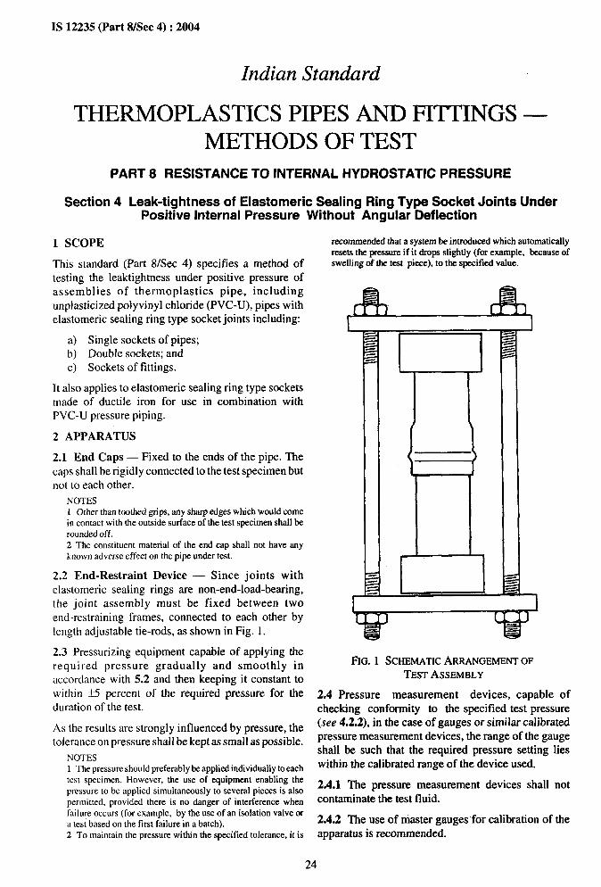
2.2 End-Restraint Device — Since joints withelastomeric sealing rings are non-end-load-bearing,the joint assembly must be fixed between twoend-restraining frames, connected to each other bylength adjustable tie-rods, as shown in Fig. 1.
2.3 Pressurizing equipment capable of applying therequired pressure gradually and smoothly inaccordance with 5.2 and then keeping it constant towithin +5 percent of the required pressure for theduration of the test.
As the results are strongly influenced by pressure, thetolerance on pressure shall be kept as small as possible.
NOTES1 The pressure should preferably be applied individually to eachtest specimen. However, the use of equipment enabling thepressure to be applied simultaneously to several pieces is alsopermitted, provided there is no danger of interference whenfailure occurs (for example, by the use of an isolation valve ora test based on the first failure in a batch).2 To maintain the pressure within the specifiedtolerance,it is
rccommerrded that a system be introduced which autrrmaticatlyresets the pressure if it dropssfightly(forexample, becauseofswellingof the test piece), to the specified value.
FIG.1 SCHEMATICARRANGEMENTOFTESTASSEMBLY
2.4Pressure measurement devices, capable ofchecking conformity to the specified test pressure(see 4.2.2), in the case of gauges or similar calibratedpressure measurement devices, the range of the gaugeshall be such that the required pressure setting lieswithin the calibrated range of the device used.
2.4.1 The pressure measurement devices shall notcontaminate the test fluid.
2.4.2 The use of master gauges for calibration of theapparatus is recommended.
*-’.-
IS 12235 (Part 8/See 4) :2004
2.5 Thermometer or other temperature-measuring 5.3 Fill the assembly with water, which may bedevice, capable of checking conformity to the preheated to a temperature 5°C above the testspecified test temperature. temperature and release any entrapped air.
2.6 Timer, capable of recording the duration of the 5.4 Condition the assembly for a period of at leastpressure applications up to the moment of failure or 20 minutes.leakage. 5.5 Connect the conditioned test specimens to the
NOTE — It is recommended that such equipment lx used whichis sensitive to pressure variations due to leaks or a failure andwhich is capable of stopping the timer and, if necessary, closingthe pressure circuit for the test specimenconcerned.
3 TEST SPECIMENS
3.1 Dimensions
Suitable lengths of pipe with socket and spigot endsshall be used. A minimum free length equal to thediameter of the pipe should be allowed between theroot of the socket and the end-capon the socket portionand between the mouth of the socket and the end-capon the spigot portion of the joint (see Fig. 1).Specimens shall not be tested within a pied of 24 hof production of the pipes.
NOTE — It is advisable to choose spigots with mean outerdiameters near the Iowertolerance limit and sockets with groovediameters near the upper tolerance limits.
3.2 Number of Test Specimens
As specified in the referring standard.
4 CALIBRATION OF THE APPARATUS
The temperature and pressure control systems, and theequipment for measuring temperature, pressure andtime, shall be calibrated to an accuracy compatiblewith the scales used and at a frequency commensuratewith the conditions of use.
5 PROCEDURE
5.1 Speeimens shall not be tested within a period of24 h of production of the pipes. Assemble the joints inaccordance with the instructions of the manufacturer.
5.2 Fix the assembled joint assembly between theframes of the end-restraint device.
pressurizing equipment and wipe d;. Progressivelyand smoothly apply the required test pressure asspecified in the referring standard to + 5 percent, in theshortest time practicable, preferably between 30s and5 rein, depending upon the material, the size of the pipeand the capability of the pressurizing equipment. Startthe timer when the test pressure is reached.
5.6 Stop the test either when the specified duration isreached, or when water is seen to leak from the joint.Leakage from any other point, such as the end caps orpressure transmission hoses or connections, does notconstitute a failure of the joint. In such a case the testhas to be repeated after rectifying the fault.
5.7 In the event of equipment failure, tests which havebeen under way for more than 100 h can be continuedprovided the equipment is reinstated within 1 day. Fortests that have been under way for more than 1000 h,the test can be continued, provided the equipment isreinstated within 3 days. Following equipment failure,if the test speeimens are closed off at the test pressureby a solenoid valve or other means, the test can becontinued in the event of periods of breakdown inexcess of that stated above. It should be noted that inthis situation, the pressure will gradually decrease dueto continuing creep in the test specimen. The timewhile the equipment is not able to function normallyshall not be included in the test time.
6 ASSESSMENT OF RESULTS
The joint is deemed to have passed the test, if noleakage from the joint is observed for a periodspecified in the referring standard.
,“
25
$ ‘:
IS 12235 (Part 9) :2004
Indian Standard
THERMOPLASTICS PIPES AND FITTINGS —METHODS OF TEST
PART 9 RESISTANCE TO EXTERNAL BLOWS (IMPACT RESISTANCE)AT O“C (ROUND-THE-CLOCK METHOD)
1 SCOPE
This standard (Part 9) specifies a method for thedetermination of the resistance to external blows ofthermoplastics pipes, including unplasticized PVCpipes.
This method is applicable to isolated batches of pipetested at O“C.
2 DEFINITIONS
For the purposes of this standard, the followingdefinitions shall apply.
2.1 True Impact Rate (TIR) — The total number offailures divided by the total number of blows, as apercentage, as if the whole batch had been tested.
NOTE — In practice, test specimens are drawn at random fromthe batch and the result is only an estimate of the TIR for thatbatch.
2.2 Failure — Shattering or any crack or split on theinside of the pipe that was caused by the impact andthat can be seen by the naked eye (lighting devices maybe used to assist in examining the specimens).
Indentation of the test specimen is not considered afailure.
3 PRINCIPLE
Test pieces are subjected to blows from a fallingstriker, of specified mass and shape, dropped from aknown height onto specified positions around thecircumference of the test specimen. The true impactrate (TIR) of the batch, or production run from anextruder, is estimated.
The severity of this test method can be adjusted bychanging the mass of the striker and/or by changingthe drop height. It is not technically correct to vary theseverity of the test by choosing values of the TIR otherthan those specified below.
The maximum acceptable values for the TIR is takento be 10 percent.
NOTE— It should be appreciated that a completely definitiveresult can be reached only by testing the whole batch. But inpractice, a balance is necessary between the statistical possibilityof a definitive result and the cost of further testing.
4 APPARATUS
4.1 Falling Weight Testing Machine —Incorporatingthe following basic components (see Fig. 1).
4.1.1 Main frame with guide rails or tube, which canbe fixed in the true vertical position, to accommodatea striker and release mechanism to release the strikerto fall vertically and freely.
4.1.2 Striker havinga nose comprising all or part of ahemisphere, combined with a stem at least 10 mmlong, and having dimensions conforming to Fig. 2 readwith Table 1. The mass of the striker, including anyassociated weights, shall be selected from the values0.5,0.8, 1.0, 1.25, 1.6,2.0,2.5,3.2,4.0, 5.0,6.3,8.3,10.0, 12.5 and 16.0 kg. The permissible tolerance onthe mass of a striker shall be * 0.5 percent. Below thestem, the nose shall be of solid steel, polished and freeof flats, indentations or other imperfections which mayinfluence the result.
Table 1 Dimensions for the Nose of the StrikerAll dimensions in millimetres.
Si Type R, “d d. a“No.(1) (2) (3) (4) (5) (6)
i) d 25 50 25t1 Fm Freeii) d 90 50 ~fl FM Free
4.1.3 Rigid specimen support, consisting of a 120°V-Block at least 200 mm long positioned so that thevertical projection of the point of impact of the fallingstriker is within 2.5 mm of the axis of the V-Block (seeFig. 1).
4.1.4 Release mechanism, such that the striker canfall from a variable height which can be adjusted toany height up to at least”2 m, measured from the topsurface of the test specimen, with an accuracy off 10 mm.
5 TEST SPECIMENS
Test specimens of length 200 + 10 mm shall be cutfrom pipe selected at random from the batch, or theproduction run from an extruder.
The cut ends shall be square to the axis of the pipe,clean and free from damage.
For pipes with outside diameters greater than 40 mm,a straight line shall be drawti along the length of eachtest specimen at a random position. Fuxther lines shallbe drawn at equal distances around the pipe piece sothat each test specimen has a number of lines given in
26
# ,.
--- . 4.- .-.
IS 12235 (Part 9) :2004
FIG.1 IMPACTTESTINGMACHINE
Table 2. The number of blows required is given in 6. the batch has a TIR less than or equal to the specifiedFor pipes with outside diameters less than or equal to level.40 mm, only one blow pertest specimen shall be made.
6.2 If the number of failures falls into the region C of
6 SAMPLING TO CONFIRM VALUE OF TIR Fig. 3, the batch can be judged to have a TIR greater
ON ISOLATED BATCHES than the specified value.
6.3 If the number of failures falls into the region B of6.1 If the number of failures from a sample falls into Fig. 3, in general further test specimensregion A of Fig. 3 (for a TIR of less than or equal to 10 t&en so that a decision can be reached.percent), then reasonable confirmation is obtained that attention is drawn to 10 for further details.
should beHowever,
# ,
27
—.. . ......
IS 12235 (Part 9): 2004
t--”dsl
-—. — -
R5
I—. -—. —.
s
10 min.
R5~
-.
2AType d25 (for Striker of Mass 0.25 kg and 0.5 kg)2B Type d90 (for Strikers of Mass
Equal to or Greater than 1 kg)
FIG. 2 NOSES OFTHE STRIKERS
6.4 The decision shall be made by using the of the test method and is given only as a guideline.
cumulative result of all the test specimens examined Evaluation of the test results shall be done based on
from the batch under consideration. Table 3. If the number of blows exceeds 124, refer to
6.5 The graph is given only to indicate the principlethe graph for assessment of results.
NUMBERS OF FAILURES —
Boundaries between regions are calculated using the following equationsSA/B= np -0.55- p _Swc = np -0.55- II dnp(l-p)
where
v = 1.282 (10 percent one sided),
P = 0.10 (TIR), andn = number of blows.
NOTES1 Initially a minimum of 25 blows shatl be made. In case of no failure, the lot is deemed to have passed the test. In case of more thanfour failures, the lot is treated as rejected. The test shatl be continued further if oneor twoor threefailursaoccurtill the results fatl intoeither region A or regionC of Table3 to arriveat a decisionfor acceptanceor rejectionrespectively.2 It is necessary to have achieved at least 25 blows without failure before the testis diseorrtinued.
FIG. 3 NUMBER OFTESTPIECESFOR10 PERCBNTTIR(AT90PERCENTCONFIDENCELEVEL)
28
.-..
.s II I.,!,-....—-.—
Table 2 Number of Equidistant Lines to beDrawn on Test Specimens
(Clause 5)
sl Nominal Outside Number of EquidistantNo. Diameter of Pipe Lhws to be Drawn
4to 104 to 104 to 104tolo4tolo5 to 105toll5toll5toll5toll5toll5toll5toll5toll5 to 125to125to126to126 to 126to126to 126 to 126 to 126to 136to 136to 136 to 136to 136to136to137 to 137to147to147 to 147to147 to 147to147 to 14
7 to 147to157 to 15I to 158 tO 158to158to158to158 to 158to158to168 to 16
7.1 The test specimens shall be conditioned in a liquidbath or in air at a temperature of O * 1°C for at leastthe period given in Table 4.
7.1.1 In case of disputes over the results, a liquid bathshall be used.
7.2 Test specimens with wall thickness up to 8.6 mmshall be tested within 10 s of their removal from airconditioning, or within 20 s of their removal fromliquid conditioning, as applicable.
7.3 Test specimens with wall thickness greater than8.6 mm shall be tested within 20 s of their removalfrom air conditioning or within 30s of their removalfrom liquid conditioning, as applicable.
7.4 If this interval is exceeded, the test specimen shallbe returned immediately to the unit for re-conditioningfor a minimum of 5 min.
Table 4 Conditioning Period(Clause 7.1)
S1 No. Wall Thickness ConditioningPeriode -
LiquidBathmm min min
(1) (2) (3) (4)
i) <8.6 15 60
ii) 8.6 to 14.1 30 120iii) >14.1 60 240
NOTE — For pipes with smooth inside and outside surfaces, thewall thickness of the pipe to be tested shall be the total wallthrough the pipe section and for pipes which are corrugated orribbed externally, the wall thickness is the thickest wall of thepipe cross-section.
8 PROCEDURE
The mass of the falling striker and the drop heightappropriate to the pipe shall be as specified in thereferring product standard.
For pipes of outside diameter 40 mm or less subjectthe test specimen to only a single blow.
For pipes of outside diameter greater than 40 mm,subject the test specimen to a blow by allowing thestriker to fall on one of the marked lines. If the testspecimen passes the test, rotate it in the V-block to thenext marked line and again subject it to a blow fromthe falling striker, after re-conditioning if necessary(see 7).
In case of corrugated or ribbed pipes, when the pitchof the pipe is over 0.25 times the shaft diameter d,ensure that the test specimen is struck on the top of thecorrugation or rib.
Continue this procedure until the test specimen failsthe test, or until all the marked lines have been struckone blow.
If required, carry out the test on subsequent testspecimens, subjecting each one to the required numberof blows.
9 EXPRESSION OF RESULTS
The result shall be expressed as A, B or C for the batchor the production run from an extruder, as follows:
a) If the TIR is below 10 percent;b) If no decision can be made on the basis of the
number of test specimens used (see 10.3); andc) If the TIR is greater than 10 percent.
NOTE — ‘fhe number of failed test specimens, as compared tothe total number of blows, should not be expressed as apercentage, to avoid confusion with the TIR, of which thepercentage is only an estimate.
10 EVALUATION OF RESULTS FROMISOLATED BATCHES (INFORMATIVE)
10.1 Scope
This clause provides information on the evaluation ofresults from isolated batches of pipe and on the use ofFig. 3. It also suggests a procedure for sampling andtesting from continuous production.
10.2 Reliability of Claims of TIR
The decision on the number of test pieces to be takenas a sample from art isolated batch should be madewith the following consideration kept in mind. Ingeneral, the precision and accuracy of the test methodis poor according to statistical laws.
This is illustrated by the following examples:
If, on testing to confirm a claim of 10 percent TIR ona sample taken at random from a batch, one test piecefails out of 100 blows, this result can only beinterpreted as meaning that the batch has a TIR ofbetween 0.1 percent and 3.9 percent (with 90 percentconfidence):
a) If 5 test pieces fail out of 100 blows, thisindicates that the batch has a TIR of between2.5 percent and 9.1 percent (with 90 percentconfidence);
b) If 9 test pieces fail out of 100 blows, thisindicates that the batch has a TIR of between5.5 percent and 13.8 percent (with 90 percentconfidence).
10,3 Isolated Batches with a Third-Pa~y QualityMark
10.3.1 Procedure given in 10.3.2 is applicable in thecase where independent certification and monitoringare applied.
10.3.2 If an isolated batch is claimed to have a TIR of10 percent or less and this claim is supported by aquality mark, this can be confirmed as follows:
I
30
#-
.—- .—...
a) If the number of failures from a sample fallsinto region A of Fig. 3, then reasonable confir-mation is obtained that the batch does not havea TIR of less than 10 percent;
b) If the number of failures falls into region B,subsequent measurements must fall into regionA for the TIR to be confirmed; and
c) If the number of failures falls into region C, theclaim given by the quality mark is not con-firmed.
10.3.3 Example
A testis made on a sample to confirm a claim to TIRof less than or equal to 10 percent:
a) If after 100 blows there are 13 or fewer failures,reasonable confirmation is obtained that thebatch has a TIR of less than or equal to10 percent. and
b) If 14 or more failures occur, the claim made bythe quality mark is not confirmed.
10.4 Isolated Batches Without a Third-PartyQuality Mark
10.4.1 If an isolated batch is claimed to have a TIR of10 percent or less; but has no quality mark, this claimmay be confirmed as follows:
a)
b)
c)
If the number of failures from a sample fallsinto region A of Fig. 3, than reasonable confir-mation is obtained that the batch has a TIR ofless than or equal to 10 percent;If the number of failures falls into region C, thebatch can be judged to have a TIR of greaterthan 10 percent; andIf the number of failures falls into region 1?,further test pieces should be taken so that adecision can be reached; this decision is made
10.4.2
IS 12235 (Part 9): 2004
by considering the cumulative result of all thetest pieces which were impact tested.
Example
A testis made on a sample to confirm a claim of TIRof less than or equal to 10 percent:
a)
b)
c)
10.5
If after 100 blows, there are not more than 5failures, reasonable confirmation is obtainedthat the batch has a TIR of less than or equal to10 percenqIf 14 or more failures cccur, the batch can bejddged to have a TIR of greater than 10percent; andIf 6 to 13 failures occur, further blows have tobe made so that a decision can be reached (forexample, if after a further 50 blows there havebeen a total of 20 failures, the batch can bejudged to have a TIR of greater than 10percent.
Suggested Sampling Procedure for Con-tinuous Production
10.5.1 At the commencement of a production runsufficient test pieces should be impact tested todemonstrate that the pipe has a TIR of equal to or lessthan 10 percent.
10.5.2 Thereafter, at intervals, not exceeding 8 h,sufficient test pieces should be taken to ensure that 25impacts may be made.
10.5.3 If no failures occur in the sample taken inaccordance with 10.5.2 production may proceed.
10.5.4 In the event of a failure Occurnng in the sampletaken in accordance with 10.5.2, further test piecesshould be tested until a positive pass or fail decision isreached (that is, the number of failures is in eitherregion A or C).
31
.-. .
IS 12235 (Part 10): 2004
Indian Standard
THERMOPLASTICS PIPES AND FITTINGS —METHODS OF TEST
PART 10 DETERMINATION OF ORGANOTIN AS TIN AQUEOUS SOLUTION
1 SCOPE
This standard (Part 10) specifies the method for thedetermination of organotin as tin aqueous solution ofthermoplastics pipe, including unplasticized PVCpipes.
2 REFERENCE
The standard listed below contains provisions which,through references in this text, constitutes provisionsof this standard. At the time of publication the editionindicated was valid. All standards are subject torevision and parties to agreements based on thisstandard are encouraged to investigate the possibilityof applying the most recent edition of the standardindicated below.
IS No. Title
1070 :1992 Reagent grade water (thirdrevision)
3 PRINCIPLE
3.1 Toluene-3,4-dithiol (dithiol) forms a colouredcomplex with an acid solution of divalent tin. Thiscolloidally dispersed red compound is used for thedetermination of tin by a spectrophotometic method.
3.2 The lower limit of the determination is about 2 ~gof tin.
4 APPARATUS
Spectrophotometer — Suitable for use in the visiblerange of the electromagnetic spectrum (400 to800 rim), with 1 and 4 cm cells.
5 REAGENTS
The reagents used shall be of recognized analyticalreagents quality. Water conforming to IS 1070 shallbe used throughout.
(sodium lautyl sulphate) in 100 ml of warmwater. The solution may lose its clarity oncooling; gentle warming will restore it.Toluene-3,4-dithiol — 2 gflitre solution. Dis-solve 2 g of toluene-3,4dithiol (dithiol) or0.28 g of zinc toluene-3,4dithiol in 5 ml of5 N sodium hydroxide. Add 1 ml of thioglycol-lic acid and dilute to 100 ml with water. Filter,if necessary. This solution should be preparedfresh daily.
NOTE— The life of this solution may be extended toabout one week if it is stored under refrigeratedconditions.
Stanalzrd tin solution — 0.2 mg Sri/ml. Dis-solve 0.200 g of tin in 100 ml of 50 percent(vfi) hydrochloric acid and dilute with thesame acid to 1000 ml.Standard tin solution — 0.02 mg Sri/ml.Prepare by diluting the solution prepared under
(g) above appropriately using 25 percent (vh)hydrochloric acid.Standard tin solution — 0.004 mg Sri/ml.Prepare by diluting the solution prepared under(g) above appropriately using 25 percent (v/v)hydrochloric acid.
6 PROCEDURE
6.1 Preparation of the Colour Standards
a) High Range (100-500 pg tin per test) — Intosix 25 ml standard one-mark volumetric flasks,transfer volumes of the 0.004 mg/ml standardtin solution [5 (j)} from Oto 5.0 ml, increasingin stages of 1.0 ml. Treat each in the followingmannec
Dilute with water to about 6 ml, add 2 drops ofthioglycollic acid [5 (c)] followed by 2 ml ofsulphuric acid [5 (d)] and mix thoroughly.Cautiously add 0.4 ml of the dodecyl sodiumsulphate solution [5 (e)] with constant swirl-ing; avoid shaking which creates foam. Con-tinue to swirl the contents of the flask whileadding 0.2 ml of toluene-3,4-dithiol solution[5 (0]. Dilute to 25 ml, stopper the flask andshake thoroughly. Fifteen minutes after theaddition of toluene-3,4-dithiol solution,measure the optical density of each solution in
32
. .....
“7
IS 12235 (Part 10): 2004
b)
a 1 cm cell at a wavelength of 535 nm standard blank. Prepare a graph of the optical(nanometres) using water as the comparative density readings against micrograms of tinstandard blank. Prepare a graph of the optical present.density readings against micrograms of tin ~.2 ~emmtiation
mesent.
bw Range (up to 100 pg tin per test) — IntoEvaporate a suitable volume of the test solution todryness, add 2 ml of dilute sulphuric acid [5 (d)] and
six 50 ml standard one-mark volumetric flasks,transfer volumes of the 0.02 mg/ml standard
evapomte until fumes of sulphur trioxide appear. Add
tin solution [5 (h)], from Oto 10.0 ml in stagesconcentrated nitric acid [5 (a)] followed by 0.2 ml of
of 2 ml each. Treat each in the following man-perchloric acid [5 (b)] and evaporate until fumes of
ner:sulphur trioxide appear.
Dilute with water to about 15 ml, add 2 dropsof thioglycollic acid [5 (c)] followed by 10 mlof the dilute sulphuric acid [5 (d)] and mixthoroughly. Cautiously add 2.0 ml of dodecylsodium sulphate solution [5 (e)] with constantswirling; avoid shaking which creates foam.Continue to swirl the contents of the flaskwhile adding 1.0 ml of toluene-3,4-dithiolsolution [5 (f)]. Dilute to 25 ml, stopper theflask and shake thoroughly. Fifteen min afterthe addition of toluene-3,4-dithiol solution,measure the optical density of each solution ina 4 cm cell at a wavelength of 535 nm(nanometers) using water as the comparative
Cool and transfer the contents of the beakerquantitatively into a 10 ml standard volumetric flaskand dilute to about 8 ml with water.
Add two drops of thioglycollic acid [5 (c)] and, withconstant swirling, 0.4 ml of dodecyl sodium sulphatesolution [5 (e)]. Add 0.2 ml of toluene-3,4-dithiolsolution [5 (f)]; dilute to the mark, stopper the flaskand shake thoroughly. Transfer a quantity to a suitablecell and 15 min after the addition oftoluene-3,4-dithiol solution, measure its opticaldensity at a wave length of 535 nm (nanometres), usingwater as the comparative standard blank. Read off theamount of tin present from the appropriate calibrationgraph.
33
* “’
‘.- . . .
‘7
IS 12235 (Part 11) :2004
Indian Standard
THERMOPLASTICS PIPES AND FITTINGS —METHODS OF TEST
PART 11 RESISTANCE TO DICHLOROMETHANE AT SPECIFIED TEMPERATURE
1 SCOPE
This standard (Part 11) specifies a method of test fordetermining the resistance of unplasticised PVC pipesto dichloromethane at a temperature specified in therelevant standard.
2 PRINCIPLE
Apiece of PVC-U pipe of specified length, chamferedat one end to an angle dependent on its thickness, isimmersed for a fixed period of time in a thermo-controlled dichloromethane bath in order to verify thatthe PVC-U is not attacked at the temperature specifiedin the standard.
NOTES1 lf the PVC has not been sufflcientty gelled, whitening of thesurface willoccur and, in the worst case, a powdery precipitatewill be produced.2 The maximum temperature at which the PVC is not attackedgives an indication of the degree and homogeneity of gelatin ofthe PVC-U of which the pipe is made. This characteristic isrelated to the mechanical properties,and in particular the long-term pressure resistance of the pipe.3 The minimum permitted bath temperature at which attack bythe dichloromethane shall not take place is specified,
3 REAGENT
3.1 Dichloromethane, Analytical Grade
NOTE — Dichlorometharte cart be toxic by absorption throughthe skin and eyes. It is, therefore, necessary to take precautionswhen handling dichloromethane or test specimens which havebeen immersed in it. Furthermore, the boiling point ofdichloromethane is low, 40”C. Consequently, it has a highvapour pressure at ambient temperatures, the vapour is alsotoxic, the threshold limit value corresponding to the maximumadmissible concentration being 500 ml/m3 (ppm). Ventilationof the room or area in which the container is kept and where thetest specimens are dried is therefore essentiat.
4 APPARATUS
4.1 Chamfering Machine
4.2 Glass or stainless-steel container of suitabledimensions to accommodate one or more testspecimens under the specified conditions (see 7.4). Amark on the inside surface to indicate a suitabledichloromethane level is useful.
4.3 Grating so fitted that it is approximately 1 cmabove the bottom of the container.
4.4 Lid to limit the evaporation of thedichloromethane.
4.5 Thermostat, to maintain the temperature of thedichloromethane at 15 t 0.5”C.
4.6 Cooling device to cool the dichloromethane to thespecified temperature.
4.7 Stirrer to homogenize the temperature of the bath.
4.8 Hood fitted with a fume extraction system.
5 USE OF THE DICHLOROMETHANE BATH
5.1 Maintain the dichloromethane at a suitable levelin the container
5.2 The consistency of colour, and hence purity of thedichloromethane in the bath shall be checked regularlyby measuring the refractive index, which shall not varyin use by more than i 0.002 from the original value.
Whenever the value of the refractive index changes bymore than ~ 0.002 from the original value, it shall bechanged.
NOTE — In practice, the refractive index will changebyO.OtM5 overa periodof 3 months,if some 700 or 800 tests arecarried out per month.
Checking the quality of the dichloromethane in thebath every 3 months should suffice.
6 PREPARATION OF THE TEST SPECIMENS
Cut from the pipe to be tested, pieces 160 mm inlength. The cut shall be square to the axis of the pipe.
If necessary, cool the test specimens to ambienttemperature.
Chamfer by machining one of the ends of each testspecimen over its complete wall thickness, the angleof chamfer depending on the wall thickness e of thepipe (see Table 1). The test specimens shall not beallowed to reach a temperature greater than 60°Cduring the machining operation.
Table 1 Details of Chamfer
S1 e aNo. mm degree
(1) (2) (3)
O ec8 10ii) 8<e<16 20
iii) e>16 30
1
34
# .
----- . .
IS 12235 (Part 11): 2004
7 PROCEDURE 8 EXPRESSION OF RESULTS
7.1 Fill the container (see 4.2) with dichloromethane 8.1 If the test specimen shows no sign of attack: ‘no(see 3.1) to a depth sufficient to cover the chamfered attack’.zone of the test specimens introduced in accordance
8.2 If the test specimen shows signs of attack,with 7.4.
describe the appearance and location of the attack.
7.2 Cover the dichloromethane with a layer of NOTE — When the attack is on the chamfer, express the result
demineralized water approximately 20 mm deep. as a percentageof the totatchamferarea(seeFig. 1).
NOTE — The purpose of the water layer is to reduce the a) Percentage attack calculated across the chamfer =
evaporation (normally 0.6 l/m2.h) of the dichloromethane and to ~xlooprotect the operator from any harmful effects of the vapour. c
7.3 Set the thermostat (see 4.5) at 15 + 0.5”C. Startb) Percentage of attack calculated round the chamfer =
the cooling device and the stirrer. --$ X1(XI
7.4 When the temperature of the bath has reached theset temperature, place the test specimens on the grating(see 4.3) so that the chamfered zone is completelyimmersed in the dichloromethane. Cover the containerwith the lid.
7.5 Leave the test specimens for 30 min in thedichloromethane, ensuring that the temperature ismaintained at the specified value.
7.6 Remove the test specimens from the containerI
with a pair of pincers (see 3.1) or use gloves.
7.7 Leave the test specimens to dry in air for at least15 min under the hood.
7.8 Examine the test specimens in accordance with 8. FIG. 1 CALCULATIONOF PERCENTAGEATTACK
35
*-.
IS 12235 (Part 12) :2004
Indian Standard
THERMOPLASTICS PIPES AND FITTINGS —METHODS OF TEST
PART 12 DETERMINATION OF TITANIUM DIOXIDE CONTENT
1 SCOPE
This standard (Part 12) specifies a method of test fordetermining the titanium dioxide content in theunplasticized polyvinyl chloride pipes and fittings.
2 PRINCIPLE
A sample of PVC-U pipe or fitting is ignited in afurnace and the resulting ash is boiled with sodiumsttlphate and sttlphuric acid. This solution is dilutedwith distilled water and the concentration of titaniumdioxide determined by spectrophotometry.
3 REFERENCE
The standard listed below contains provisions whichthrough references in this text, constitutes provisionsof this standard. At the time of publication the editionindicated was valid. All standards are subject torevision and parties to agreements based on thisstandard are encouraged to investigate the possibilityof applying the most recent edition of the standardindicated below:
IS No. Title
1070:1992 Reagent grade water — Specifica-tion
4 REAGENTS AND APPARATUS
4.1 Reagents
Except where otherwise specified, only reagents ofrecognized analytical grade and only waterconforming to IS 1070 shall be used.
4.1.1 Sulphuric Acid (Density 1840 kg/m3)
4.1.2 Anhydrous Sodium Sulphate
4.1.3 Hydrogen Peroxide (30 percent)
4.1.4 Stdphuric Acid—10 percent solution (1 partconcentrated sttlphuric acid added to 9 parts ofdistilled water).
4.1.5 Rutile titanium dioxide of average assay 97percent TiOz.
4.2 Apparatus
4.2.1 Ultra violethisible range spectrophotometer setto read at 408.0 t 0.2 mm.
4.2.2 Muffle furnace capable of being maintained at850 * 10”C.
4.2.3 Analytical balance with 0.1 mg accuracy.
4.2.4 Hotplate
4.2.5 Porcelain or Silica Crucibles — 50 ml volume.
4.2.6 Thermometers capable of indicating therequired temperatures to an accuracy of* 2°C.
4.2.7 Standard laboratory glassware.
5 PREPARATION OF THE TEST SAMPLE
The bulk sample shall be prepared by finely milling asuitable length of pipe or section of fitting and thenmixing it uniformly. No preconditioning of the testsamples is required.
Test portions for analysis are randomly selected fromthis bulk sample.
NOTE — Fragments or pieces obtained from an impact test maybe used.
6 PROCEDURE
6.1 Standards Preparation
6.1.1 Weigh out approximately 100 mg of titaniumdioxide commercial grade of approx 97 percent purityto the nearest 0.1 mg and record the mass determined.Transfer the TiOz to a 250 ml beaker and add 1.5 g ofanhydrous sodium sulphate and 50 ml of concentratedsulphuric acid. Add boiling chips, cover the beakerwith a watch glass, and heat to boiling point on ahotplate until the solid material has dissolved.
6.1.2 When the solution has cooled, add to itapproximately 100 ml of distilled water, stirringcontinuously. After cooling transfer the solution to a500 ml volumetric flask containing approximate y200 ml of distilled water, and make up to the markwith distilled water.
6.2 Preparation of the Standard Curve
6.2.1 Prepare standard TiOz Soltttions in thefollowing concentrations:
0.00, 0.02, 0.04, 0.06, 0.08 and 0.10 mg/ml bytransferring O, 5.0, 10.0, 15.0,20.0 and 25.0 ml ofthe standard solution into separate 50 ml volumetric
36
IS 12235 (Part 12): 2004
flasks and dilute almost to volume with 10 percentsulphuric acid solution. Add 2.0 ml of 30 percenthydrogen peroxide solution to each of thevolumetric flasks, dilute to volume with 10 percentsulphuric acid solution, shake and leave in a darkcupboard for approximately 30 rein, withoccasional further shaking.
6.2.2 Using the spectrophotometer, determine theabsorbance of each solution at a wave length of408 nm using 1.0 cm cells with a blank of 2.0 ml 30percent hydrogen peroxide in 50 ml 10 percentsulphuric acid solution.
6.2.3 From these results plot a standard curve(absorbance versus concentration in mg/ml).
6.3 Sample Preparation
6.3.1 For samples containing in the region of 5percent TiOz, weigh out approximately 1.5 g of the testportion.
6.3.2 For samples containing in the region of 0.6percent Ti02, weigh out approximately 3.0 g of the testportion.
6.3.3 Weigh the appropriate amount of sample to thenearest 0.1 mg into a 50 ml porcelain or silica crucibleand record the mass (M).
6.3.4 Heat the crucible, gently at first, with a bunsenburner until charring is complete and the evolution ofcopious white fumes has ceased.
6.3.5 Transfer the crucible to a muffle furnacemaintained at 850 t 10”C and ignite to a white or palegray ash. (This takes approximately 4 h.)
NOTE — Sometimes the solutionis slightty cloudy, but ttds hss00 effect on the find result.
6.3.7 Allow the crucible to cool and then carefullytransfer the contents of the beaker containing 200 mlof distilled water. Thoroughly wash the crucible withfurther aliquots of distilled water.
6.3.8 After cooling, transfer the solution to a 500 mlvolumetric flask and make up the volume (Vl ) with
distilled water.
6.4 Determination of Titanium Dioxide in theSample Solution
6.4.1 Transfer 20 ml (Vs) of the sample solutionprepared in 6.3.8 to a 50 ml volumetric flask and dilutealmost to volume with 10 percent sulphuric acidsolution. Add 2.0 ml of 30 percent hydrogen peroxide,make up to volume (V2) with 10 percent sulphuric acidsolution, shake and leave in a dark cupboard for30 rein, with occasional further shaking.
6.4.2 Determine the absorbance of the sample asi n 6.2.2. Should the absorbance fall outside thecalibration range, repeat the determination using asuitable aliquot of sample solution.
6.4.3 Determine the concentration C, in mg/ml, ofTi02 in the final solution, from the standard curve.
7 CALCULATIONS
Titanium dioxide content shall be calculated asfollows:
c v; V2Ti02 content in percent by= ~ x 100mass of pipe or fitting
where
6.3.6 Allow the crucible to cool, then add 1.5 g of C = concentration of TiOz in the final
anhydrous ammonium sulphate and 25 ml of solution, in mg/ml;
concentrated sulphuric acid, followed by boiling M = mass of test portion sample, in mg;
chips. Cover the crucible with a watch glass and bring VI = total volume of sample solution, in ml;the contents to a boil on the hot plate (take care to V2 = volume of solution prepared, in ml; andavoid spattering or spillage). A clear solution should
V3 = volume of solution transferred out ofresult.
total volume of sample solution, in ml.
.,
i ,
II
* ..
37
IS 12235 (Part 13): 2004
Indian Standard
THERMOPLASTICS PIPES AND FITTINGS —METHODS OF TEST
PART 13 DETERMINATION OF TENSILE STRENGTH AND ELONGATION
1 SCOPE
This standard (Part 13) specifies a method fordetermining the tensile properties, includingelongation, of thermoplastic pipes, including PVC-Upipes.
2 REFERENCE
The standard listed below contains provisions, which,through references in this text constitutes provisionsof this standard. At the time of publication the editionsindicated was valid. All standards are subject torevision and parties to agreements based on thisstandard are encouraged to investigate the possibilityof applying the most recent edition of the standardindicated below:
IS No. Title
8543 (Part 4/ Methods of testing plastics: Part 4Sec 1) :1984 Short term mechanical properties,
Section 1 Determination of tensileproperties
3 APPARATUS
3.1 Tensile Testing Machine — Testing machinewith grips that can be separated at one or more (asrequired) of the rates given below:
Speed A : 1 mm/min + 50 percentSpeed B : 5 mm/min * 20 percentSpeed C : 50 mndmin * 10 percentSpeed D : 100 mndmin * 10 percentSpeed E : 500 mm/min + 10 percent
3.1.1 Speed ofSeparation — The speed of separationis the rate at which the two grips are separated fromeach other. Unless otherwise agreed the speed ofseparation shall be maintained at 50 mtrdmin t 10percent.
3.1.2 Grips — Grips for holding the test specimen,one being attached to a fixed or essentially stationarymember of the machine and the other a movablemember. The grips are self-aligning; that is, they areattached to the fixed and movable memberrespectively in such a manner that they will movefreely into alignment as soon as any load is applied, sothat the long axis of the test specimen will coincidewith the direction of the applied pull through the centre
line of the grip assembly. The test specimen is held insuch a way that slip relative to the grips is preventedas far as possible. The grips may be of a type thattighten automatically under load.
3.1.3 Load Indicator — Suitable load-indicatingmechanism capable of showing the total tensile loadcarried by the test specimen when held by the grips.This mechanism is essentially free from inertia lag atthe specified rate of testing and indicates the load withan accuracy of f 1 percent of the indicated value, orbetter.
3.1.4 Extension Indicator — A suitable instrumentfor determining, at any time during the test, thedistance between two fixed points located within themiddle parallel-sided part of the test specimen. It isdesirable, but not essential, that this instrument shouldautomatically record this distance (or any change in it)as a function of the load on the test specimen, or of theelapsed time from the start of the test, or both. If onlydistance as a function of elapsed time is recorded,load-time data are also taken. The instrument isessentially free of inertia lag at the specified speed oftesting and is accurate to * 1 percent of strain, or better.For the measurement of modulus of elasticity, theinstrument is capable of measuring the distancebetween the lines to an accuracy off 0.1 mm.
3.2 Micrometer — Screw micrometer reading to atleast 0.02 mm for measuring the width and thicknessof the specimen.
4 PREPARATION OF TEST SPECIMENS
4.1 Dimensions of test specimens shall be as given inFig. 1.
4.1.1 The specimens shall be cut or machined fromlengths of pipe in the longitudinal direction, that is,along the pipe axis.
4.1.2 If for any reason, it is not possible to use thestandard test specimen shown in Fig. 1, a test specimenof similar form and with dimensions having a constantratio to those of Fig. 1 maybe used, in which case therate of separation of grips should be adjusted so thatthe middle parallel part of the specimen is strained atthe rate that is appropriate to the standard testspecimen.
38
#
-—..-
IS 12235 (Part 13): 2004
/ REFERENCE LINESR 60 min.
FIG. 1 DIMENSIONSOF TEST SPECIMEN
4.1.3 When reference lines are marked on testspecimens, this is done with ink or other suitablemedium that will not affect the material being tested.Reference lines should not be scratched, punched orimpressed upon the specimens.
5 NUMBER OF TEST SPECIMENS
5.1 At least five test specimens are tested.
5.2 The specimens that do not break within theparallel portion are discarded and further testspecimens are tested.
6 CONDITIONING OF THE SPECIMENS
Test specimens are conditioned as specified in therelevant material specification. In the absence of anysuch directive, the test specimens shall be conditionedin an atmosphere with a temperature of 27 * 2°C and65+ 5 percent relative humidity for 24 h.
7 PROCEDURE
7.1 Measure the width and thickness of the specimenat five equally spaced points on the parallel sidedportion to the nearest 1 percent with a micrometerprescribed in 3.2. Place the test specimen in the gripsof the testing machine, taking care to align the longaxis of the specimen and the grips with an imaginaryline joining the points of attachment of the grips to themachine. Tighten the grips of the testing machine to adegree necessary to prevent the test specimen fromslipping during the test, but not to the point where thespecimen would be crushed.
7.2 Set the speed of the machine and start themachine. Note the following:
a) Load at yield point,b) Distance between the reference lines at the
yield point,c) Load at break or maximum load, andd) Distance between the reference lines at break.
The above information may be obtained from anautographically recorded stress-strain curve or may bedirectly observed.
8 CALCULATION AND EXPRESSION OFRESULTS
8.1 Tensile Stress at Yield, Tensile Stress atMaximum Load and Tensile Stress at Break
The load in kilograms-force at yield or the maximumload, or the load at break, as appropriate, is divided bythe original minimum cross-sectional area of the testspecimen (average of five values of the cross-sectionobtained in 7.1) in cm2. The results are expressed inkgf/cm2 and reported to three significant figures.
8.2 Percentage Elongation at Yield and
Percentage Elongation at Break
The extension at the yield point (see Fig. 2) or theextension at the moment of break, as appropriate, isdivided by the original distance between the referencelines and multiplied by 100. The percentageelongation at yield or at break is reported to twosignificant places.
8.3 For each of the results of the five test specimens,the arithmetic mean of all values is calculated to threesignificant figures (except for elongation, which iscalculated to two significant figures) and reported asthe average value for the particular property inquestion.
8.4 If the standard deviation is required, it iscalculated as follows and is reported to two significantfigures:
s = @x2 - &)/(n-l)
where
s =
x =
n =
xbm =
estimated standard deviation;
value of single observation;
number of observations; and
arithmetic mean of theobservations.
set of
39
*’
IS 12235 (Part 13) :2004
II---- ____ --- -—-.
INITIAL LINEARPORTION OFCURVE
//
\-
/’ YIELD POINT/
/
,/’
SPECIFIEDOFFSET EXTENSION ~
FIG.2 LOAD/EXTENSIONDIAGRAM
9 TEST REPORT e)
The test report shall include the following as f)
appropriate: g)h)
a) Complete identification of the material tested,including type, source, manufacturer’s name; j)form, principle dimension;
b) Conditioning procedure used; k)c) Method of preparation of test specimen; m)d) Atmospheric conditions in the test room;
Number of test specimens tested;Speed of testing;Tensile stress at yield, average value;Tensile stress at maximum load or at break,average value;Percentage elongation at yield or at break, orboth, average values;Standard deviations of the test results; andDate of test.
‘
40
7------
II . . . .. —----
IS 12235 (Part 14): 2004
Indian Standard
THERMOPLASTICS PIPES AND FITTINGS —METHODS OF TEST ●
PART 14 DETERMINATION OF DENSITY/RELATIVE DENSITY (SPECIFIC GRAVITY)
1 SCOPE
This standard (Part 14) specifies a method of test forthe determination of density or relative density(specific gravity) of non-cellular plastics pipes andfittings.
2 PRINCIPLE
Relative density is determined by applying thedisplacement principle, which involves weighing ofthe specimen in air and subsequently in water.
3 REFERENCES
The standard listed below contain provisions, whichthrough reference in this text constitute provisions ofthis standard. At the time of publication the editionsindicated were valid. All standards are subject torevision and parties to agreements based on thisstandard are encouraged to investigate the possibilityof applying the most recent editions of the standardindicated below:
IS No. Title
196:1966 Atmospheric conditions for testing
13360 (Part 3/ Plastics — Methods of testing: PartSec 1) :1995 3 Physical and dimensional proper-
ties, Section 1 Determination ofdensity and relative density of non-cellular plastics
4 DEFINITIONS
4.1 Density p —The ratio of the mass of the sampleto its volume Vt (at the temperature t), expressed inkg/m3, g/cm3 or g/ml.
4.2 Relative Density — The ratio of the mass of agiven volume of material at the temperature t 1 to thatof an equal volume of a reference material at thetemperature t2 is expressed as relative density, at fl
and t2 where t is the temperature in degrees Celsius.Relative density may also be defined as the ratio of asubstance to the density of a reference substance underconditions that are specific for both substances.
5 APPARATUS AND MATERIAL
5.1 Analytical balance with a precision of 0.1 mg.
5.2 Corrosion resistant wire of very fine gauge forsuspending the specimen. A strand from standardhousehold electrical copper cabling is adequate.
5.3 A beaker or other wide-mouthed vesset forholding the water and immersed specimen.
5.4 Supporting bridge for the vessel such that it canbe placed over the pan, and the pan is free to movewithout any hindrance.
5.5 Thermometer with an accuracy of t 1°C.
5.6 Substantially air-free distilled or demineralisedwater.
6 TEST SPECIMENS
6.1 The test specimen shall be a single piece,weighing between 2 g and 20 g, but optimally around4 g, cut from a portion of pipe to any size and shapethat can be conveniently tested, $rovided that itsvolume shall not be less than 1 cm . The surface andedges of the test specimen shall be smooth. Careshould be taken while cutting the specimen to avoidchanges in density resulting from compressive stressesor frictional heating.
6.2 The specimen shall be free of oil, grease, dust andother foreign matter.
7 PROCEDURE
7.1 Weigh the specimen in air to the nearest 0.1 mg.
7.2 Attach to the balance a piece of fine wiresufficiently long to reach from the hook above the panto the support for the immersion vessel. Attach thespecimen to the wire such that it is suspended about2.5 cm above the support for the immersion vessel.
NOTE — The specimen may be weighed in air after hangingfrom the wire. In this case, record the mass of the specimen, a =(mass of specimen+ wire, in air) - (mass of wire in air).
7.3 Mount the immersion vessel on the support, andcompletely immerse the suspended specimen in thewater at a temperature of 27 * 2“C. The vessel shallnot touch the wire or specimen. Remove any bubblesadhering to the specimen and wire, paying particularattention to the holes in the specimen. Usually, thesebubbles can be removed by rubbing them with anotherpiece of wire. If it is not possible to remove bubblesby this method or if bubbles are continuously beingformed due to gases dissolved in the water, the use of
I
41
IS 12235 (Part 14): 2004
vacuum is recommended (see Note under 7.2). Weighthe suspended specimen to the required precision (seeNote). Record this mass as b (mass of the specimenand partially immersed wire in water). Lhd’essotherwise specified, weigh rapidly in order to.avoidabsorption of water by the specimen.
NOTE — It may be necessary to change the sensitivityadjustment of the balance to overcome the damping effect of theimmersed specimen.
7.4 Weigh the wire in water with immersion to thesame depth as used in 7.3. Record this mass as m (massof the wire in liquid).
8 CALCULATIONS
Calculate the density of the specimen as follows
PT
where
a =
b =
m=
=0.9965 a/(a+m-b)
apparent mass of the specimen, withoutwire, in aiq
apparent mass of specimen completelyimmersed in water and wire partiallyimmersed in wateu and
apparent mass of partially immersedwire.
42
IS 12235 (Part 15): 2004
Indian Standard
THERMOPLASTICS PIPES AND FITTINGS —METHODS OF TEST
PART 15 DETERMINATION OF VINYL CHLORIDE MONOMER CONTENT
1 SCOPE
This standard (Part 15) specifies a method fordetermining the concentration of vinyl chloridemonomer in PVC-U pipes and fittings.
2 PRINCIPLE
A solution of the PVC-U pipe or fitting inNN-dimethylacetamide (DMA) contained in a sealedglass vial is equilibrated at 45°C. The vinyl chloridemonomer (VCM) content of the sample is determinedby the gas chromatographic analysis of a sample of thehead space vapour.
3 APPARATUS
3.1 Gas Chromatography — For manual orautomated head space injections and flame ionizationdetector.
3.2 Gas Chromatography Columns — (See AnnexA for suitable columns) 2 m x 2 mm stainless steelpacked with porapak Q80/100.
The column shall be capable of completely separatingthe air peak, the vinyl chloride peak from the standardsolution and the internal standard peak, if used.
The signal obtained with a solution containing0.02 mg/1 of vinyl chloride shall be at least five timesthat of the background noise.
NOTE — A carbowax or modified porapak type column isrecommended for the rare instances when porapak Q showsunsatisfactory resolution of VCM from interfering substances.
3.3 Digital Integrator
3.4 Glass Vials — Nominal 25 ml capacity equippedwith butyl rubber septa and aluminium sealing caps,together with a manual crimping tool for sealing thevials.
NOTE — The dimensions of the vials are unimportant, but it isnecessary to select containers of equivalent volume.
3.7 Glassware — Borosilicate glass, as appropriate.
4 REAGENTS
4.1 NN-dimethylacetamide (DMA) — analyticalgrade.
NOTE— In practice, new batches of DMA are screened forpotential interferences. If DMA is of inferior purity, usually asingle distillation (collect cut 163 to 166°C at 760 mm) isacceptable.
4.2 Vinyl chloride monomer, of purity greater than99.5 percent, stored in a stainless steel sample cylinderof 500 ml, approximate capacity, fitted with needlevalves. From this pure VCM, f 2 percent accuratelycertified 100 p 1/1to 1000 ~ l/1VCM in air or nitrogensamples are made for the preparation of calibrationstandards.
NOTE — VCM is a gas at ambient temperatures and isflammable and carcinogenic; spcciat care should be taken toavoid the inhalation of VCM vapours. Preparations must becarried out under a well ventilated hood.
5 PROCEDURE
5.1 Sample Preparation
Weigh 0.500 f 0.005 g cut from the pipe or fitting intoa glass vial, add 5.0 ml DMA, seal the vial andequilibrate at 45 * 2°C overnight. In the initial hour ortwo of heating, gently agitate the contents to ensure allof the sample has dissolved or disintegrated.
5.2 Standards Preparation
Prepare an approximate 20 mg/ml solution of VCM inDMA as follows:
a)
b)c)
d)
e)
Fill a 50 ml graduated flask with DMA towithin approximately 10 ml of the graduation,Stopper the flask with a rubber septum,Slowly bubble VCM into the DMA through asyringe barrel and ~eedle. Vent the flask witha second syringe needle,After several minutes, remove both the needlesand re-weigh, andUsing a syringe, make up to the volume withDMA and calculate the actual VCM con-centration of the standard solution. Alternat-ely, a gas sampling bulb (at least 20 mlcapacity), which is quantitatively filled at at-mospheric pressure with a certified VCM gasstandard, may be used. No more than 5 percentof the capacity of the bulb is removed for thepreparation of standards.
NOTE — After preparation, liquid standards must be storedunder refrigerated condkions. When this is done, the standardsare stable for up to one month.
43
- ..
IS 12235 (Part 15): 2004
5.3 Control Preparation 5.5 Sample Determination
Select a control sample of PVC-U so that the VCMcontent is below the detection limit (see 6). Prepare aset of samples of this control as described in 5.1. Useone of these samples for the blank determination.Prepare calibration standards over an appropriateVCM concentration range, by spiking the remainderof the set of solutions with varying amounts of thestandard VCM mixture. Equilibrate, overnight at45 i 2°c.
5.4 Calibration
The calibration standards shall be prepared as follows:
5.4.1 After equilibration, inject 0.5 ml of the headspace vapour (see Note 1) from each calibrationstandard straight into the gas chromatography using thefollowing parameters:
a) Column temperature : approx. 130°C(see Note 2)
b) Injection port temperature : 150 t 2°Cc) Detector temperature : 150i2°Cd) Carrier : Nz at approx.
30 ml/min(see Note 2)
NOTES1 For automatic injections, an injection time is selected to giveas near as possible to the prescribed injection volume. Ifsensitivity is a problem for samples containing less than0.05 mglkg VCM, the injection time may be increased.However, larger injection volumes lead to larger air packs andother volatile compounds which may be present and which maycause some interference problems. Therefore, it is important tocheck that the blank does not show any interference in the VCMregion of the cbromatogram.2 Column temperature and the carrier rate may be alteredslightly to give a VCM retention time of 3 * 1 min.
5.4.2 Determine and record the mean response factor(amount per area or amount per peak height) for thewhole set of standards.
If the blank contains major interfering peaks or givespoor resolution between VCM and other peaks, thecolumn is unsuitable and one of different polarity maybe chosen.
5.5.1 Take a sample volume of head space vapour, asselected in 5.4 of the sample which was prepared asin 5.1 and inject into the gas chromatography. Amaximum of two aliquots may be taken from any onevial.
5.5.2 Measure the peak heights and determine thelevel of the VCM present by comparison with theresponse factors in 5.4.2 (b).
NOTE — The presence of VCM shouldbeconfirmed on at leastone sample of a set of determinations of each specificcommodity. The recommended methodfor the identificationofVCM is by means of mass spectrometry.
6 DETECTION LIMIT
The detection limit is arbitrarily defined as theequivalent of 3 percent to 4 percent full scaledeflection with the gas chromatography set atmaximum sensitivity.
The detection limit depends on the partitioncoefficient of VCM between the air in the head spaceand the sample in the vial.
The estimated detection limits using the standardconditions is 0.3 mg/kg for pipe wall sections.
7 ACCURACY
The estimated possible error varies according to theVCM level being determined. Below a level of 0.05mg/lcg the possible error is of the order of t 25 percent,whereas above 0.05 mglkg if is approximately * 6 to10 percent. These estimates presuppose no systematicerror on the part of the operator on the preparation ofcalibration standards.
8 REPORT
The following information shall be reported:
a) Type andlor class, size and configuration ofpipe or fitting tested, and
b) VCM content reported to the nearest 0.5mg/kg.
44
.6A. -.
IS 12235 (Part 15): 2004
ANNEX A
(Ckzuse 3.2)
SUITABLE COLUMNS FOR THE DETERMINATION OF VINYL CHLORIDE MONOMER INHOMOPOLYMER AND COPOLYMER RESINS
sl Column Length, Diameter, Stationary Support OperatingNo. m mm Phase Temperature Range
1‘ThiscolumnmaYnotbe suitablefor determinationson copolymers of vinylchlorideandvinY1acetate. VWAC
45
*’
... ,*_e _
IS 12235 (Part 16): 2004
Indian Standard
THERMOPLASTICS PIPES AND FITTINGS —METHODS OF TEST
PART 16 HIGH TEMPERATURE TEST
1 SCOPE
This standard (Part 16) specifies a method of test forthe matrix of thermoplastics pipes and fittings,including those made of unplasticized PVC, usinghigh temperatures.
2 PRINCIPLE
This test indicates the presence of volatiles and gasbubbles resulting from incorrect processing conditionsor thermal decomposition. The test also provides anindication of gelatin levels in extruded PVC-U pipes.A pipe section is heated in an oven, then sliced intosegments, which are examined for splits, delaminationor porosity.
3 APPARATUS
3.1 An electrically heated air oven with internalcirculation fan, the whole interior of whichis maintained automatically at a temperature of180 * 4°C,
3.2 Thermometer capable of indicating the requiredtemperature to an accuracy of * 2°C
4 TEST SPECIMENS
The test specimen shall consist of a complete sectionof pipe of 200 mm minimum length. The ends shall becut reasonably square.
5 PROCEDURE
5.1 Pre-heat the oven to 180 * 4°C and allow tostabilize for at least 15 min.
5.2 Place the test specimen in the oven, standing itvertically on one end.
5.3 Allow the specimen to iemain in the oven for a
period of 60 ~ ~ min at the prescribed temperature.
5.4 Remove the test specimen from the oven andplace it on a cutting board. Slice the test specimen witha stainless steel knife in the axial direction into piecesnot larger than 50 mm in width.
5.5 Examine the pieces visually and record theexistence of any splits, delamination bubbles orporosity.
6 REPORT
Report shall contain the following:
a)
b)
Type, class, size and configuration of pipetested, andAny splits, delamination, bubbles or porosity.
46
B’
IS 12235 (Part 17): 2004
Indian Standard
THERMOPLASTICS PIPES AND FITTINGS —METHODS OF TEST
PART 17 DETERMINATION OF ASH CONTENT AND SULPHATED ASH CONTENT
1 SCOPE
This standard (Part 17) specifies methods ofdetermination of the ash content of pipes and fittingsmade of unplasticized polyvinyl chloride (PVC-U).These methods can also be used for PVC resins andcompounds.
NOTE — Polyvinyl chloride evolves hydrogen chloride onthermal decomposition, and precautions should be taken to avoidinhalation of fumes.
2 PRINCIPLE
2.1 Method A
Direct calcination that is by burning the organic matterand heating the residue at 850”C until constant massis reached.
2.2 Method B
Calcination, with sulphuric acid treatment aftercombustion, that is by burning the substance andtransforming the residue into sulphates usingconcentrated sulphuric acid, and finally, heating theresidue at 850”C until constant mass is reached.Should lead compounds be present, method B isrecommended.
3 REAGENTS
(For Method B only). Sulphuric acid (density 184.0kg/m3) of recognized analytical grade.
4 APPARATUS
4.1 Crucible of silica or platinum, inert to thematerial tested. The size shall be sufficient that thecrucible is not more than half filled by the sample.
4.2 Bunsen Burner, with silica triangle and tripod, orother suitable heating device.
4.3 Muffle Furnace, capable of being controlledthermostatically at 850 f 50°C.
4.4 Pipette, of appropriate capacity (For Method Bonly).
4.5 Dessicator, containing an effective drying agentthat does not react chemically with the ashcomponents.
NOTE — In some cases, the affinity of the ash for water maybegreater than that of the drying agents commonly used.
4.6 Analytical Balance, accurate to 0.1 mg.
5 PROCEDURE
5.1 Method A
5.1.1 Prepare the crucible by heating in the mufflefurnace at 850 f 50”C until constant mass is reached.Allow to cool in the dessicator to room temperature,but for at least 1 h, and weigh to the nearest 0.1 mg.
5.1.2 Introduce into the crucible 2 g to 5 g of thesample and reweigh. Heat the crucible directly on theheating device so that the sample bums slowly and lossof ash is avoided. Continue this operation until nomore smoke is evolved.
5.1.3 Place the crucible at the entrance of the mufflefurnace maintained at 850 t 50”C (the temperature inthe entrance zone is about 300”C to 400”C), thenadvance the crucible slowly into the furnace. Calcineslowly (to prevent loss of ash particles) for 30 min at850 f 50”C.
5.1.4 Remove the crucible from the furnace. Place itin the dessicator, allow to cool to room temperature,but for at least 1 h, and weigh to the nearest 0.1 mg.
5.1.5 Calcine again, under the same conditions, untilconstant mass is reached, that is, until the results oftwo consecutive weighings do not differ by more than0.5 mg. The duration of the heating in the furnace shallnot, however, exceed 3 h; if constant mass is notattained after this time, the mass after 3 h shall be used
for calculating the result.
5.2 Method B
5.2.1 Proceed as in 5.1.1 and 5.1.2.
5.2.2 After allowing the crucible and its contents tocool, add sulphuric acid dropwise by means of a
pipette of suitable capacity until the residue is soakedcompletely. Heat carefully on a suitable heating deviceuntil the evolution of smoke ceases, taking care toavoid spattering of the contents of the crucible.
5.2.3 If, after allowing the crucible to cool, carbon isstill evident, add 1 to 5 drops of sulphuric acid andreheat until evolution of white fumes has ceased.
5.2.4 Place the crucible at the entrance of the mufflefurnace maintained at 850 + 50”C and proceed asdetailed in 5.1.3, 5.1.4 and 5.1.5. The residue, aftercalcination, shall be white.
47
*
IS 12235 (Part 17): 2004
6 NUMBER OF DETERMINATIONS 8 TEST REPORT
Carry out two determinations. Calculate the The test report shall contain the following tmrticulars:arithmetical mean of the results. If the individual test
a)results differ from each other by more than 10 percent
b)of their mean, repeat the procedure until twosuccessive results satisfy this requirement.
7 EXPRESSION OF RESULTS c)
The ash or sulphated ash content, expressed in gramsper 100 g of sample, is given by the formula:
d)(ml /mO ) x 100 e)
wheref)
mo = mass, in grams, of the test portion, and
ml = mass, in grams, of ash obtained.
-.
A reference to this standard,Complete identification of the sample, includ-ing type, manufacturer’s code number, source,trade name, etc.,Method used, that is,Method A — ash at 850°C andMethod B — sulphated ash at 850”C,Mass of each of the two test portions used,Individual results of the two determinationsand the mean ash content, andIf constant mass is not attained after 3 h, reportthat fact (see 5.1.5).
48
IS 12235 (Part 18): 2004
Indian Standard
THERMOPLASTICS PIPES AND FITTINGS —METHODS OF TEST
PART 18 DETERMINATION OF RING STIFFNESS
1 SCOPE
This standard (Part 18) specifies the method for thedetermination of the ring stiffness of thermoplasticspipes, including unplasticized polyvinyl chloride(PVC-U) pipes having a circular cross-section, underparallel-plate loading.
2 PRINCIPLE
The ring stiffness is determined by measuring the forceand the deflection while deflecting the pipe at aconstant rate. A length of pipe supported horizontallyis compressed vertically between two parallei platesmoved at a constant speed which is dependent of thediameter of the pipe. A plot of force versus deflectionis generated. The ring stiffness is calculated as afunction of the force necessary to produce a deflectionof 3 percent diametrically across the pipe.
3 DEFINITIONS
3.1 Initial Internal Diameter (di) — The average ofthe inside diameters of the test specimen expressed inmetres.
3.2 Vertical Deflection (y) — Measured change ofthe inside diameter in the direction of the loadapplication expressed in metres.
3.3 Percentage Deflection (P) — The ratio of thereduction in pipe inside diameter to the pipe initialdiameter expressed as a percentage of the initial insidediameter.
3.4 Load (F) — The load applied to the pipe toproduce a given percentage deflection, expressed inkN.
3.5 Length (L) — The average length of the testspecimen expressed in metres.
3.6 Ring Stiffness (S) — The value obtained bydividing the force per unit length of specimen by theresulting deflection in the same units at the prescribedpercentage deflection and multiplied by a factor,expressed in kN/m2.
4 APPARATUS
4.1 Testing Machine — A properly calibratedcompression testing machine of the
constant-rate-of-crosshead-movement type, shall beused for the tests. The rate of head movement shall bein accordance with Table 1, with sufficient force andtravel to produce the specified deflection through theparallel plates.
4.2 Loading Plates — The load shall be applied tothe specimens through two parallel steel bearingplates. The plates shall be flat, smooth and clean. Thethickness of the plates shall be sufficient so that nobending or deformation occurs during the test, but itshall not be less than 6.0 mm. The plate length shallequal or exceed the specimen length and the platewidth shall not be less than the pipe contact width atmaximum pipe deflection plus 25 mm.
4.3 Deformation (Deflection) Indicator — Thechange in the inside diameter or deformation parallelto the direction of loading, shall be measured with asuitable instrument accurate to the nearest 0.25 mm.The instrument shall not support the pipe test specimenor the plate, or in any way affect the load deflectionmeasurements. Changes in diameter maybe measuredduring loading by continuously recording plate travel.
4.4 Measuring devices, capable of measuring:
a)b)
c)
Length of the test specimen to within 1 mm,Internal diameter of the test specimen to within0.5 percent, andChange in inside diameter of the test specimenin the-direction of loading with an accuracy of0.1 mm or 1 percent of the deflection, whichever is greater.
4.5 Force-measuring device, capable of determiningto within 2 percent the force necessary to produce
-{
49
IS 12235 (Part 18): 2004
1 percent to 4 percent deflection of the test specimendiametrically across the test specimen.
5 TEST SPECIMENS
5.1 Marking
The pipe from which the specimens are to be cut shallbe marked on the outside along its full length with aline parallel to the pipe axis. Three test specimens,marked a, b, and c, shall be tested for each sample ofpipe. The ends of the test specimens shall bereasonably square to the axis of the pipe, free of burrsand jagged ends and the lengths shall conform to 5.2.
5.2 Length
5.2.1 The length of the test specimen shall bedetermined by calculating the arithmetic mean of nlength measurements, made to within 1 mm, equallyspaced around the circumference of the pipe inconformation with Table 2. For each individual testspecimen, the smallest of the length measurementsshall not be less than 0.9 times the largest.
Table 2 Number of Length Measurements(Clause 5.2. 1)
S1No. Nominal Diameter Number of Lengthd“ of Pipe Measurements, n
mm
(1) (2) (3)
i) dn < 200 3
ii) 200<dn <500 4
iii) dn >500 6
5.2.2 For pipes with nominal diameter less than orequal to 1 500 mm, the average length of each testspecimen shall 300 t 10 mm.
5.2.3 For pipes that have a nominal diameter, dn,greater than 1500 mm, the average length of each testspecimen shall be 0.2 dn.
5.2.4 Structured-wall pipes with perpendicular ribs orcorrugations or other regular structures shall be cutsuch that each test specimen contains the minimumwhole number of ribs, corrugations or other structuresnecessary to conform to 5.2.2 and 5.2.3 (see Fig. 1).The cuts shall be made at the mid point between theribs, corrugations or other structures.
5.2.5 Helically wound pipes shall be cut such thateach piece contains the minimum whole number ofhellical windings necessary to conform to 5.2.2and 5.2.3 (see Fig. 2).
5.3 Inside Diameter
Determine inside diameter, dia, dib, dic, of each testspecimen as the arithmetic mean of fourmeasurements made at 45° intervals along one cross-section of the test specimen. Finally, calculate the
—
—
e.g. =45 mm
FIG. 1 TEST PIECE CtJT OUT OFA
L0“5 p
PERPENDICULARLYFUBBEDPIPE
F’=’p —
-- bl-e.g. p=65mm
FIG. 2 TEST PIECE CUTOUT OF A HELICALLYWOUND PIPE
50
- *,., -
average internal diameter, & of all three testspecimens as
di = (di~ + dib ~ d~.)/3
An example of a device for measuring the insidediameter of corrugated pipes is shown in Fig. 3.
5.4 Average Outside Diameter
Measure the average outside diameter of each testspecimen in accordance with Part 1 of this standard.
5.5 Wall Thickness
Measure the wall thickness in accordance with Part 1of this standard evenly spaced points along theperimeter of each test specimen. Note the maximumand minimum values and calculate the average. Markthe point of minimum wall thickness, if any, on eachtest specimen.
6 CONDITIONING
The test specimens shall beat least 24 h old. For typetesting and in cases of dispute, the age of the test shallbe 21 t 2 days.
6.1 Condition the pipe samples for at least 24 h in air,at a temperature of 27 + 2°C, and conduct the test atthe same temperature.
6.2 In case of dispute, the specimens shall beconditioned at a temperature of 23 f 2°C and a relative
IS 12235 (Part 18): 2004
humidity of 50 t 5 percent for 40 h and the testconducted under the same conditions.
7 PROCEDURE
7.1 Locate the pipe specimen with its longitudinalaxis parallel to the bearing plates and centre it laterallyin the testing machine.
7.2 If an orientation of minimum wall thickness hasbeen found, place the first specimen with the thinnestportion on top. Rotate each successive specimen 35°and 70°. If no minimum wall thickness has been found,use any base line.
7.3 With the deflection indicator in place, bring theupper plate in contact with the specimen with no moreload than necessary to hold it in place. This establishesthe beginning point for the measurement of subsequentdeflections.
7.4 Compress the specimen at a constant speedspecified in Table 1, while continuously recording theforce and deflection.
7.5 Typically, the force and deflection measurementsare generated continuously by measuring thedisplacement of one of the plates, but if, during the test,the pipe-wall height ec (see Fig. 4) changes by morethan 10 percent, generate force/deflection plot bymeasuring the change in the inside diameter of the testspecimen.
FIG. 3 EXAMPLE OF A DEVICEFORMEASURINGTHEINSIDEDIAMETEROFA CORRUGATEDPIPE
~yEii ir~=~FIG. 4 EXAMPLESOFTHEPIPE-WALL HEIGHT, et
51
.— -, -.
IS 12235 (Part 18): 2004
7.6 Iftheforce/deflection plot, which is typically asmooth curve, indicates that the zero point may beincorrect (see Fig. 5), extrapolate back the initialstraight-line portion of the curve anduse the intersectwith the horizontal axis as the (0,0) point (origin).
NOTE — Procedure for plotting load versus deflection is givenin Annex A for information.
8 CALCULATIONS
Calculate the ring stiffness, S., Sb, SC, of each of thethree test specimens using the following equations:
Sa= {0.018 6+0.025 @a/dJ)(Fa/Lay~
Sb= {0.018 6+0.025 ~di)}( Fb/Lbyb)
Sc = (0.018 6 + 0.025 @c/di)) ( Fc / L.cyc)
where
F = force, in kN, corresponding to 3.0percent pipe deflection;
L = length, in metres, of the test specimen;and
Y = deflection in metres, corresponding to3.0 percent deflection, that is, y/di = 0.03
t
L.
:uoL
Calculate the ring stiffness of the pipe, in kN/m2, asthe mean of these three values, using the followingequation:
S=($a+Sb+S~)/3
9 TEST REPORT
Report the following information:a)b)c)
d)e)
f-)
g)
h)
j)
Complete identification of the samples tested;All dimensions of each specimen;Conditioning time, temperature and environ-ment;Testing temperature and environment;The calculated values of Sa, Sb and SC of thering stiffness of each test specimen, to threedecimal places;The calculated value of the ring stiffness S, totwo decimal places;If required, a force/deflection plot for each testspecimen;Any factors which may affect the results; andDate of report.
{,/’ ‘:)A
APPARENT ZERODEFLECTION, y ~
. .
1 ~APPARENT zERO
CORRECTED ZERO
FIG.5 METHODOFCORRECTINGTHE ORIGIN
52
-. .’,-. . .
IS 12235 (Part 18): 2004
ANNEX A
(Clause 7.6)
PLOTTING LOAD VERSUS DEFLECTION
A-1 The load versus deflection plot is typically a be inerror(seeFig. 6). In such cases, the initial straightsmooth curve. In some cases, for example, when the line portion of the curve shall be extrapolate back, and
curve is generated automatically, the zero point may this intercept be used as the (0,0) point.
ILOAD
I ESTIMATEDZERO(0,0)
— DE FL ECTION~
FIG.6 METHODOF ESTIMATINGTHE ORIGIN
IS 12235 (Part 19): 2004
Indian Standard
THERMOPLASTICS PIPES AND FITTINGS —METHODS OF TEST
PART 19 FLAITENING TEST
1 SCOPE
This standard (Part 19) specifies a method for thedetermination of resistance to damage on flatteningunder load, of thermoplastics pipe, includingunplasticized pol yvinyl chloride (PVC-U) pipe.
2 APPARATUS
2.1 Testing Machine — A properly calibratedcompression testing machine of the constant-rate-of-crosshead-movement type, shall be used for the tests.The rate of head movement shall be in accordance withTable 1, with sufficient force and travel to produce thespecified deflection through the parallel plates.
2.2 Loading Plates — The load shall be applied tothe plates through two parallel steel bearing plates.The plates shall be flat, smooth and clean. Thethickness of the plates shall be sufficient so that nobending or deformation occurs during the test, but itshall not be less than 6.0 mm. The plate length shallequal or exceed the specimen length and the platewidth shall not be less than the pipe contact width atmaximum pipe deflection plus 25 mm.
2.3 Deformation (Deflection) Indicator — Thechange in the inside diameter or deformation parallelto the direction of loading, shall be measured with asuitable instrument accurate to the nearest 0.25 mm.The instrument shall not support the pipe test specimenor the plate, or in any way affect the load deflectionmeasurements. Changes in diameter maybe measuredduring loading by continuously recording plate travel.
2.4 Measuring devices, capable of measuring:
a) Length of the test specimen to within 1 mm,b) Internal diameter of the test specimen to within
0.5 percent, and
c) Change in inside diameter of the test specimenin the direction of loading with an accuracy of0.1 mm, or 1 percent of the deflection, whichever is greater.
3 PROCEDURE
3.1 Cut three samples, each 50 mm long, from the pipeto be tested. The ends shall be square, smooth and freefrom cracks, chips or other imperfections.
3.2 Place the samples, one at a time, between twoparallel plates of a suitable press and flatten thesamples until the distance between the plates is 40percent of the outside diameter of the pipe or the innerwalls of the sample touch, whichever occurs first. Therate of loading shall be uniform and such that thecompression is completed within 2 to 5 min.
NOTE — The platesof the press should be made of steel at least6 mm thick and they should be wider than the width of contactof the compressed pipe sample and longer than the length of thesame sample under test.
3.3 Remove the load and examine the samples forevidence of splitting, cracking or breaking.
BIS is a statutory institution established under the Bureau of Irrdian Standardr Act, 1986 to promoteharmonious development of the activities of standardization, marking and quality certification of goods and
,,
attending to connected matters in the country. “1
Copyright
BIS has the copyr :ht of all its publications. NO part of these publications may be reproduced in any form ~ .j
without the prior permission in writing of BIS. This does not preclude the free use, in the ‘course of implementing ,:
the standard, of necessary details, such as symbols and sizes, type or grade designations. Enquiries relating to i Icopyright be addressed to the Director (Publications), BIS.
(1Review of Indian Standards
1 ‘1Amendments are issued to standards as the need arises on the basis of comments. Standards are also reviewed
periodically; a standard along with amendments is reaffirmed when such review indicates that no changes areneeded; if the review indicates that changes are needed, it is taken up for revision. Users of Indian Standardsshou Id ascertain that they are in possession of the latest amendments or edition by referring to the latest issue of‘BIS Catalogue’ and ‘Standards: Monthly Additions’.
This Indian Standard has been developed from Dot: No. CED 50 (5837 to 5855).
Amendments Issued Since Publication
[
,,/
Amend No. Date of Issue Text Affected
BUREAU OF INDIAN STANDARDS
Headquarters:
Manak Bhavan, 9 Bahadur Shah Zafar Marg, New Delhi 110002Telephones: 23230131,23233375,2323 9402 website: www.bis.org.in
Regional Offices: Telephones
Central :
Eastern :
Northern :
Southern :
Western :
Branches :
Manak Bhavan, 9 Bahadur Shah Zafar Marg{
23237617NEW DELHI 110002 23233841
1/14 C.I.T. Scheme VII M, V.I.P. Road, Kankurgachi{