Disclosure to Promote the Right To Information Whereas the Parliament of India has set out to provide a practical regime of right to information for citizens to secure access to information under the control of public authorities, in order to promote transparency and accountability in the working of every public authority, and whereas the attached publication of the Bureau of Indian Standards is of particular interest to the public, particularly disadvantaged communities and those engaged in the pursuit of education and knowledge, the attached public safety standard is made available to promote the timely dissemination of this information in an accurate manner to the public. इंटरनेट मानक “!ान $ एक न’ भारत का +नम-ण” Satyanarayan Gangaram Pitroda “Invent a New India Using Knowledge” “प0रा1 को छोड न’ 5 तरफ” Jawaharlal Nehru “Step Out From the Old to the New” “जान1 का अ+धकार, जी1 का अ+धकार” Mazdoor Kisan Shakti Sangathan “The Right to Information, The Right to Live” “!ान एक ऐसा खजाना > जो कभी च0राया नहB जा सकता ह ै” Bhartṛhari—Nītiśatakam “Knowledge is such a treasure which cannot be stolen” IS 13360-5-4 (2013): Plastics - Methods of Testing, Part 5: Mechanical Properties, Section 4: Determination of Izod Impact Strength [PCD 12: Petroleum, Coal, and Related Products]
Transcript
Disclosure to Promote the Right To Information
Whereas the Parliament of India has set out to provide a practical regime of right to information for citizens to secure access to information under the control of public authorities, in order to promote transparency and accountability in the working of every public authority, and whereas the attached publication of the Bureau of Indian Standards is of particular interest to the public, particularly disadvantaged communities and those engaged in the pursuit of education and knowledge, the attached public safety standard is made available to promote the timely dissemination of this information in an accurate manner to the public.
इंटरनेट मानक
“!ान $ एक न' भारत का +नम-ण”Satyanarayan Gangaram Pitroda
“Invent a New India Using Knowledge”
“प0रा1 को छोड न' 5 तरफ”Jawaharlal Nehru
“Step Out From the Old to the New”
“जान1 का अ+धकार, जी1 का अ+धकार”Mazdoor Kisan Shakti Sangathan
“The Right to Information, The Right to Live”
“!ान एक ऐसा खजाना > जो कभी च0राया नहB जा सकता है”Bhartṛhari—Nītiśatakam
“Knowledge is such a treasure which cannot be stolen”
“Invent a New India Using Knowledge”
है”ह”ह
IS 13360-5-4 (2013): Plastics - Methods of Testing, Part 5:Mechanical Properties, Section 4: Determination of IzodImpact Strength [PCD 12: Petroleum, Coal, and RelatedProducts]
B U R E A U O F I N D I A N S T A N D A R D SMANAK BHAVAN, 9 BAHADUR SHAH ZAFAR MARG
NEW DELHI 110002
Hkkjrh; ekud
IykfLVd — ijh{k.k i¼fr;k¡Hkkx 5 ;kaf=kd xq.kèkeZ
vuqHkkx 4 vk;tksM lq?kV~; lkeF;Z Kkr djuk
(igyk iqujh{k.k )
Indian Standard
PLASTICS — METHODS OF TESTINGPART 5 MECHANICAL PROPERTIES
Section 4 Determination of Izod Impact Strength
( First Revision )
ICS 83.080.01
IS 13360 (Part 5/Sec 4) : 2013ISO 180 : 2000
Price Group 5June 2013
Plastics Sectional Committee, PCD 12
NATIONAL FOREWORD
This Indian Standard (Part 5/Sec 4) (First Revision) which is identical with ISO 180 : 2000 ‘Plastics— Determination of Izod impact strength’ issued by the International Organization for Standardization(ISO) was adopted by the Bureau of Indian Standards on the recommendation of the Plastics SectionalCommittee and approval of the Petroleum, Coal and Related Products Division Council.
This standard was originally published in 1996 which was identical with ISO 180 : 1993. The firstrevision of this standard has been undertaken to align it with the latest version of ISO 180 : 2000.
The text of ISO Standard has been approved as suitable for publication as an Indian Standard withoutdeviations. Certain conventions are, however, not identical to those used in Indian Standards. Attentionis particularly drawn to the following:
a) Wherever the words ‘International Standard’ appear referring to this standard, they should beread as ‘Indian Standard’.
b) Comma (,) has been used as a decimal marker while in Indian Standards, the current practiceis to use a point (.) as the decimal marker.
In this adopted standard, reference appears to certain International Standards for which IndianStandards also exist. The corresponding Indian Standards which are to be substituted in theirrespective places are listed below along with their degree of equivalence for the editions indicated:
International Standard Corresponding Indian Standard Degree of Equivalence
ISO 291 : 19971) Plast ics —Standard atmospheres forconditioning and testing
ISO 293 : 2004 Plast ics —Compression moulding testspecimens of thermoplast icmaterials
ISO 294-1 : 1996 Plastics —Injection moulding of test specimensof thermoplastic materials — Part 1:General principles, and moulding ofmultipurpose and bar test specimens
ISO 295 : 2004 Plast ics —Compression moulding of testspecimens of thermosett ingmaterials
ISO 2602 : 1980 Stat ist icalinterpretation of test results —Estimation of the mean —Confidence interval
IS 196 : 1966 Atmospheric conditionsfor testing (revised)
IS 13360 (Part 2/Sec 1)2) Plastics —Methods of testing: Part 2 Samplingand preparation of test specimens,Section 1 Compression mouldingtest specimens of thermoplasticmaterials (first revision)
IS 13360 (Part 2/Sec 3) : 2000Plastics — Methods of testing: Part 2Sampling and preparation of testspecimens, Section 3 Injectionmoulding of test specimens ofthermoplastic materials — Generalprinciples, and moulding ofmultipurpose and bar test specimens
IS 13360 (Part 2/Sec 2) : 2013Plastics — Methods of testing: Part 2Sampling and preparation of testspecimens, Section 2 Compressionmoulding of test specimens ofthermosetting materials(first revision)
IS 14277 : 1996 Stat ist icalinterpretation of test results —Estimation of mean, standarddeviation and regression coefficient— Confidence interval
Technically Equivalent
Identical
do
do
Technically Equivalent
(Continued on third cover)1) Since revised in 2008.2) Under print.
1 Scope
1.1 This International Standard specifies a method for determining the Izod impact strength of plastics underdefined conditions. A number of different types of specimen and test configurations are defined. Different testparameters are specified according to the type of material, the type of test specimen and the type of notch.
1.2 The method is used to investigate the behaviour of specified types of specimen under the impact conditionsdefined and for estimating the brittleness or toughness of specimens within the limitations inherent in the testconditions.
1.3 The method is suitable for use with the following range of materials:
! rigid thermoplastic moulding and extrusion materials, including filled and reinforced compounds in addition tounfilled types; rigid thermoplastics sheets;
! rigid thermosetting moulding materials, including filled and reinforced compounds; rigid thermosetting sheets,including laminates;
! fibre-reinforced thermosetting and thermoplastic composites incorporating unidirectional or non-unidirectionalreinforcements such as mat, woven fabrics, woven rovings, chopped strands, combination and hybridreinforcements, rovings and milled fibres and sheet made from pre-impregnated materials (prepregs);
! thermotropic liquid-crystal polymers.
1.4 The method is not normally suitable for use with rigid cellular materials and sandwich structures containingcellular material. Also, notched specimens are not normally used for long-fibre-reinforced composites orthermotropic liquid-crystal polymers.
1.5 The method is suited to the use of specimens which may be either moulded to the chosen dimensions,machined from the central portion of a standard multipurpose test specimen (see ISO 3167) or machined fromfinished or semifinished products such as mouldings, laminates and extruded or cast sheet.
1.6 The method specifies preferred dimensions for the test specimen. Tests which are carried out on specimensof different dimensions or with different notches, or specimens which are prepared under different conditions, mayproduce results which are not comparable. Other factors, such as the energy capacity of the apparatus, its impactvelocity and the conditioning of the specimens can also influence the results. Consequently, when comparativedata are required, these factors must be carefully controlled and recorded.
1.7 The method should not be used as a source of data for design calculations. Information on the typicalbehaviour of a material can be obtained, however, by testing at different temperatures, by varying the notch radiusand/or the thickness and by testing specimens prepared under different conditions.
Indian Standard
PLASTICS — METHODS OF TESTINGPART 5 MECHANICAL PROPERTIES
Section 4 Determination of Izod Impact Strength
( First Revision )
IS 13360 (Part 5/Sec 4) : 2013ISO 180 : 2000
1
2 Normative references
The following normative documents contain provisions which, through reference in this text, constitute provisions ofthis International Standard. For dated references, subsequent amendments to, or revisions of, any of thesepublications do not apply. However, parties to agreements based on this International Standard are encouraged toinvestigate the possibility of applying the most recent editions of the normative documents indicated below. Forundated references, the latest edition of the normative document referred to applies. Members of ISO and IECmaintain registers of currently valid International Standards.
ISO 291:1997, Plastics ! Standard atmospheres for conditioning and testing.
ISO 293:1986, Plastics ! Compression moulding test specimens of thermoplastic materials.
ISO 294-1:1996, Plastics ! Injection moulding of test specimens of thermoplastic materials ! Part 1: Generalprinciples, and moulding of multipurpose and bar test specimens.
ISO 295:1991, Plastics ! Compression moulding of test specimens of thermosetting materials.
ISO 1268:19741), Plastics ! Preparation of glass fibre reinforced, resin bonded, low pressure laminated plates orpanels for test purposes.
ISO 2602:1980, Statistical interpretation of test results ! Estimation of the mean ! Confidence interval.
ISO 2818:1994, Plastics ! Preparation of test specimens by machining.
ISO 3167:—2), Plastics ! Multipurpose test specimens.
ISO 10724-1:1998, Plastics ! Injection moulding of test specimens of thermosetting powder moulding compounds(PMCs) ! Part 1: General principles and moulding of multipurpose test specimens.
ISO 13802:1999, Plastics ! Verification of pendulum impact-testing machines ! Charpy, Izod and tensile impact-testing.
3 Terms and definitions
For the purposes of this International Standard, the following terms and definitions apply.
3.1Izod unnotched impact strengthaiUimpact energy absorbed in breaking an unnotched specimen, referred to the original cross-sectional area of thespecimen
NOTE It is expressed in kilojoules per square metre (kJ/m2).
3.2Izod notched impact strengthaiNimpact energy absorbed in breaking a notched specimen, referred to the original cross-sectional area of thespecimen at the notch, with the pendulum striking the face containing the notch
NOTE It is expressed in kilojoules per square metre (kJ/m2).
1) Under revision as a series of 11 parts.
2) To be published. (Revision of ISO 3167:1993)
2
IS 13360 (Part 5/Sec 4) : 2013ISO 180 : 2000
3.3parallel impactp"laminar-reinforced plastics# impact with the direction of blow parallel to the plane of reinforcement
NOTE The direction of the blow in the Izod test is usually “edgewise parallel” (ep) (see Figure 1).
3.4normal impactn"laminar-reinforced plastics# impact with the direction of blow normal to the plane of reinforcement
NOTE This kind of impact is not usually used with the Izod test, but is indicated for the sake of completion (see alsoFigure 1).
4 Principle
The test specimen, supported as a vertical cantilever beam, is broken by a single impact of a striker, with the line ofimpact a fixed distance from the specimen clamp and, in the case of notched specimens, from the centreline of thenotch (see Figure 2).
5 Apparatus
5.1 Test machine
5.1.1 The principles, characteristics and verification of suitable test machines are detailed in ISO 13802.
5.1.2 Some plastics are sensitive to clamping pressure. When testing such materials, a means of standardizingthe clamping force shall be used and the clamping force shall be recorded in the test report. The clamping forcecan be controlled by using a calibrated torque wrench or a pneumatic or hydraulic device on the vice clampingscrew.
5.2 Micrometers and gauges
Micrometers and gauges capable of measuring the essential dimensions of test specimens to an accuracy of0,02 mm are required. For measuring the dimension bN of notched specimens, the micrometer shall be fitted withan anvil of width 2 mm to 3 mm and of suitable profile to fit the shape of the notch.
6 Test specimens
6.1 Preparation
6.1.1 Moulding and extrusion compounds
Specimens shall be prepared in accordance with the relevant material specification. When none exists, and unlessotherwise specified, specimens shall be either directly compression moulded or injection moulded from the materialin accordance with ISO 293, ISO 294-1, ISO 295 or ISO 10724-1 as appropriate, or machined in accordance withISO 2818 from sheet that has been compression or injection moulded from the compound. Specimens may also becut from multipurpose test specimens complying with ISO 3167, type A.
IS 13360 (Part 5/Sec 4) : 2013ISO 180 : 2000
3
Key
1 Direction of blow 3 Fixed vice jaw2 Movable vice jaw 4 Optional groove
Edgewise (e) and flatwise (f) indicate the direction of the blow with respect to the specimen thickness h and specimen width b.Normal (n) and parallel (p) indicate the direction of the blow with respect to the laminate plane.
The usual Izod test is "edgewise parallel". When h = b, parallel as well as normal impact testing is possible.
Figure 1 — Scheme of designations describing the direction of blow
4
IS 13360 (Part 5/Sec 4) : 2013ISO 180 : 2000
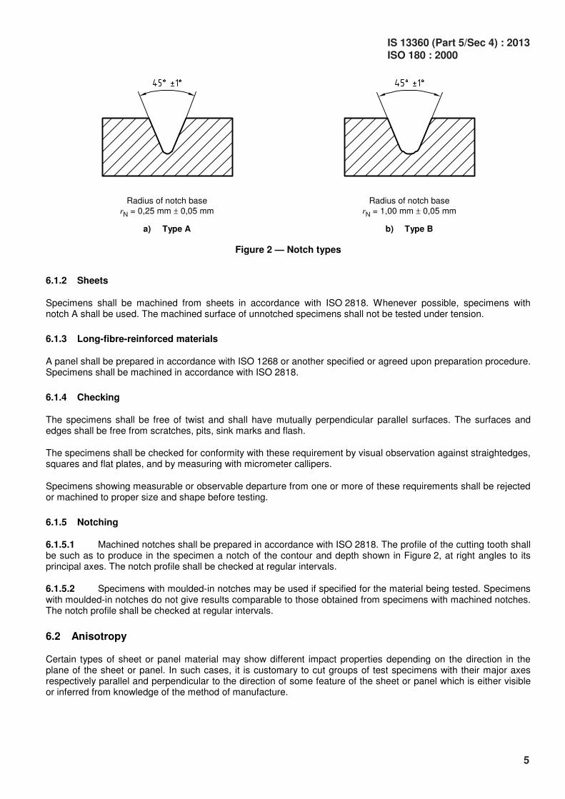
Radius of notch baserN = 0,25 mm ! 0,05 mm
a) Type A
Radius of notch baserN = 1,00 mm ! 0,05 mm
b) Type B
Figure 2 — Notch types
6.1.2 Sheets
Specimens shall be machined from sheets in accordance with ISO 2818. Whenever possible, specimens withnotch A shall be used. The machined surface of unnotched specimens shall not be tested under tension.
6.1.3 Long-fibre-reinforced materials
A panel shall be prepared in accordance with ISO 1268 or another specified or agreed upon preparation procedure.Specimens shall be machined in accordance with ISO 2818.
6.1.4 Checking
The specimens shall be free of twist and shall have mutually perpendicular parallel surfaces. The surfaces andedges shall be free from scratches, pits, sink marks and flash.
The specimens shall be checked for conformity with these requirement by visual observation against straightedges,squares and flat plates, and by measuring with micrometer callipers.
Specimens showing measurable or observable departure from one or more of these requirements shall be rejectedor machined to proper size and shape before testing.
6.1.5 Notching
6.1.5.1 Machined notches shall be prepared in accordance with ISO 2818. The profile of the cutting tooth shallbe such as to produce in the specimen a notch of the contour and depth shown in Figure 2, at right angles to itsprincipal axes. The notch profile shall be checked at regular intervals.
6.1.5.2 Specimens with moulded-in notches may be used if specified for the material being tested. Specimenswith moulded-in notches do not give results comparable to those obtained from specimens with machined notches.The notch profile shall be checked at regular intervals.
6.2 Anisotropy
Certain types of sheet or panel material may show different impact properties depending on the direction in theplane of the sheet or panel. In such cases, it is customary to cut groups of test specimens with their major axesrespectively parallel and perpendicular to the direction of some feature of the sheet or panel which is either visibleor inferred from knowledge of the method of manufacture.
IS 13360 (Part 5/Sec 4) : 2013ISO 180 : 2000
5
6.3 Shape and dimensions
6.3.1 General
For the dimensions of the test specimen, see Table 1.
Where necessary with certain types of apparatus, the length may be shortened symmetrically to 63,5 mm.
The longitudinal direction of the notch is always parallel to the thickness h.
a If specimens are taken from sheet or products, the thickness h of the sheet or product shall be added to the designation.
Unreinforced specimens shall not be tested with their machined surface under tension.
b If the sheet thickness h equals the width b, the direction of the blow (normal n, or parallel p) shall be added to the
designation.
6.3.2 Moulding and extrusion compounds
Test specimens with one of two different types of notch shall be used as specified in Table 1 and shown inFigure 2. The notch shall be located at the centre of the specimen.
The preferred type of notch is type A. If information on the notch sensitivity of the material is desired, specimenswith notch types A and B shall be tested.
6.3.3 Sheet materials, including long-fibre-reinforced materials
The recommended thickness h is 4 mm. If the specimen is cut from a sheet or a piece taken from a structure, thethickness of the specimen, up to 10,2 mm, shall be the same as the thickness of the sheet or the structure.
Specimens taken from pieces thicker than 10,2 mm shall be machined to 10 mm $ 0,2 mm from one surface,providing that the sheet is homogeneous in its thickness and contains only one type of reinforcement uniformlydistributed. If unnotched specimens are tested, the original surface shall be tested under tension, in order to avoidsurface effects.
Specimens shall be tested edgewise parallel, with the exception of specimens with h = b = 10 mm which can betested parallel or normal to the laminate plane (see Figure 1).
6.4 Number of test specimens
6.4.1 Unless otherwise specified in the standard for the material being tested, a set consisting of 10 specimensshall be tested. When the coefficient of variation (see ISO 2602) has a value of less than 5 %, a minimum numberof five test specimens is sufficient.
6.4.2 If laminates are tested in the normal and parallel directions, 10 specimens shall be used for each direction.
6
IS 13360 (Part 5/Sec 4) : 2013ISO 180 : 2000
6.5 Conditioning
Unless otherwise specified in the standard for the material under test, the specimens shall be conditioned for atleast 16 h at 23 °C and 50 % relative humidity in accordance with ISO 291, unless other conditions are agreedupon by the interested parties. In the case of notched specimens, the conditioning time is after notching.
7 Procedure
7.1 Conduct the test in the same atmosphere as that used for conditioning, unless otherwise agreed upon by theinterested parties, e.g. for testing at high or low temperatures.
7.2 Measure the thickness h and width b of each test specimen, in the centre, to the nearest 0,02 mm. In thecase of notched specimens, carefully measure the remaining width bN to the nearest 0,02 mm.
In the case of injection-moulded specimens, it is not necessary to measure the dimensions of each specimen. It issufficient to measure one specimen from a set to make sure that the dimensions correspond to those in Table 1.With multiple-cavity moulds, ensure that the dimensions of the specimens are the same for each cavity.
7.3 Check that the impact machine is able to perform the test with the specified velocity of impact and that it is inthe correct range of absorbed energy W which shall be between 10 % and 80 % of the available energy at impact,E. If more than one of the pendulums conform to these requirements, the pendulum having the highest energy shallbe used.
7.4 Determine the frictional losses and correct the absorbed energy in accordance with ISO 13802.
7.5 Lift the pendulum to the prescribed height and support it. Place the specimen in the vice and clamp it asshown in Figure 1, in accordance with 5.1.2. When determining the notched Izod impact strength, the notch shallbe positioned on the side that is to be struck by the striking edge of the pendulum.
7.6 Release the pendulum. Record the impact energy absorbed by the specimen and apply any necessarycorrections for frictional losses, etc. (see 7.4).
7.7 Four types of break designated by the following code-letters may occur:
C complete break: a break in which the specimen separates into two or more pieces
H hinge break: an incomplete break such that both parts of the specimen are held together only by a thinperipheral layer in the form of a hinge having low residual stiffness
P partial break: an incomplete break that does not meet the definition for hinge break
N non-break: there is no break, and the specimen is only bent and pushed through the support blocks,possibly combined with stress whitening
8 Calculation and expression of results
8.1 Unnotched specimens
Calculate the Izod impact strength of unnotched specimens, aiU, expressed in kilojoules per square metre, usingthe following equation:
3ciU 10
Ea
h b! "
#
(1)
where
Ec is the corrected energy, in joules, absorbed by breaking the test specimen;
IS 13360 (Part 5/Sec 4) : 2013ISO 180 : 2000
7
h is the thickness, in millimetres, of the test specimen;
b is the width, in millimetres, of the test specimen.
8.2 Notched specimens
Calculate the Izod impact strength of notched specimens, aiN, expressed in kilojoules per square metre, withnotches A or B, using the following equation:
3ciN
N10
Ea
h b! "
#
(2)
where
Ec is the corrected energy, in joules, absorbed by breaking the test specimen;
h is the thickness, in millimetres, of the test specimen;
bN is the remaining width, in millimetres, of the test specimen.
8.3 Statistical parameters
Calculate the arithmetic mean of test results and the standard deviation of the mean value, if required, using theprocedure given in ISO 2602. For different types of failure within one sample, the relevant numbers of specimensshall be given and mean values shall be calculated.
8.4 Significant figures
Report all calculated mean values to two significant figures.
9 Precision
The precision of this method is not known because interlaboratory data are not available. When interlaboratory dataare obtained, a precision statement will be added at the following revision.
10 Test report
The test report shall include the following information:
a) a reference to this International Standard;
b) the method used, designated in accordance with Table 1, for example:
c) all information necessary for identification of the material tested, including type, source, manufacturer’s code,grade and history, where these are known;
d) a description of the nature and form of the material, i.e. whether a product, semifinished product, test plate orspecimen, including principal dimensions, shape, method of manufacture, etc., where these are known;
e) the velocity of impact;
8
IS 13360 (Part 5/Sec 4) : 2013ISO 180 : 2000
f) the nominal pendulum energy;
g) the clamping pressure, if applicable (see 5.1.2);
h) the method of test specimen preparation;
i) if the material is in the form of a product or a semifinished product, the orientation of the test specimen inrelation to the product or semifinished product from which it was cut;
j) the number of specimens tested;
k) the standard atmosphere used for conditioning and testing, plus any special conditioning treatment if requiredby the standard for the material or product;
l) the type(s) of failure observed;
m) the individual test results, presented as follows (see also Table 2):
1) group the results according to the three basic types of failure:
C complete break, including hinge break H
P partial break
N non-break
2) select the most frequent type and record the mean value x of the impact strength for this type of failure,followed by the letter C or P for the type of failure,
3) if the most frequent failure type is N, record the letter N only,
4) add (between brackets) the letter C, P or N for the second most frequent failure type, but only if itsfrequency is higher than 1/3 (if not relevant, insert an asterisk);
n) the standard deviations of the mean values, if required;
o) the date(s) of the test.
IS 13360 (Part 5/Sec 4) : 2013ISO 180 : 2000
9
Table 2 — Presentation of results
Type of failure
C P NDesignation
x * * xC*
x (P) * xC(P)
x * (N) xC(N)
* x * xP*
(C) x * xP(C)
* x (N) xP(N)
* * N N*
(C) * N N(C)
* (P) N N(P)
x Mean value of impact strength for most frequent failure type, excluding
type N.
C, P or N Most frequent failure type.
(C), (P) or (N) Second most frequent failure type, to be recorded only if its frequency is
higher than 1/3.
* Not relevant.
10
IS 13360 (Part 5/Sec 4) : 2013ISO 180 : 2000
(Continued from second cover)
International Standard Corresponding Indian Standard Degree of Equivalence
ISO 2818 : 1994 Plast ics —Preparation of test specimens bymachining
ISO 3167 : 2002 Plast ics —Multipurpose test specimens
ISO 10724-1 : 1998 Plastics —Injection moulding of test specimensof thermosetting powder mouldingcompounds (PMCs) — Part 1:General principles and moulding ofmultipurpose test specimens
IS 13360 (Part 2/Sec 4) : 1999Plastics — Methods of testing: Part 2Sampling and preparation of testspecimens, Section 4 Preparation oftest specimens by machining (firstrevision)
IS 13360 (Part 2/Sec 5) : 2013Plastics — Methods of testing: Part 2Sampling and preparation of testspecimens, Section 5 Multipurposetest specimens (first revision)
IS 13360 (Part 2/Sec 10) : 2006Plastics — Methods of testing: Part 2Sampling and preparation of testspecimens, Section 10 Injectionmoulding of test specimens ofthermosetting powder mouldingcompounds (PMCs) — Generalprinciples and moulding ofmultipurpose test specimens
Identical
do
do
The technical committee has reviewed the provisions of the following International Standards referredin this adopted standard and has decided that they are acceptable for use in conjunction with thisstandard:
International Standard Title
ISO 1268 : 1974 Plastics — Preparation of glass fibre reinforced, resin bonded, lowpressure laminated plates or panels for test purposes
ISO 13802 : 1999 Plastics — Verification of pendulum impact-testing machines — Charpy,Izod and tensile impact-testing
For tropical countries like India, the standard temperature and the relative humidity shall be taken as27 ± 2oC and 65 ± 5 percent, respectively.
In reporting the result of a test or analysis made in accordance with this standard, if the final value,observed or calculated, is to be rounded off, it shall be done in accordance with IS 2 : 1960 ‘Rules forrounding off numerical values (revised)’.
Bureau of Indian Standards
BIS is a statutory institution established under the Bureau of Indian Standards Act, 1986 to promote
harmonious development of the activities of standardization, marking and quality certification of goods
and attending to connected matters in the country.
Copyright
BIS has the copyright of all its publications. No part of these publications may be reproduced in any form
without the prior permission in writing of BIS. This does not preclude the free use, in course of imple-
menting the standard, of necessary details, such as symbols and sizes, type or grade designations.
Enquiries relating to copyright be addressed to the Director (Publications), BIS.
Review of Indian Standards
Amendments are issued to standards as the need arises on the basis of comments. Standards are also
reviewed periodically; a standard along with amendments is reaffirmed when such review indicates that
no changes are needed; if the review indicates that changes are needed, it is taken up for revision. Users
of Indian Standards should ascertain that they are in possession of the latest amendments or edition by
referring to the latest issue of ‘BIS Catalogue’ and ‘Standards: Monthly Additions’.
This Indian Standard has been developed from Doc No.: PCD 12 (2488).
Amendments Issued Since Publication______________________________________________________________________________________
Amendment No. Date of Issue Text Affected______________________________________________________________________________________


![IS 13360-1 (1992): Plastics - Methods of Testing, Part 1: Introduction · Introduction [PCD 12: Plastics] 18 13360 ( Part 1 ) : 1992 SrTch TIT WfeT - Ta-m vT&d YTrl 1 WmPW Indian](https://static.documents.pub/doc/80x56/5f32b434099000637a5dbec3/is-13360-1-1992-plastics-methods-of-testing-part-1-introduction-introduction.jpg)


