Disclosure to Promote the Right To Information Whereas the Parliament of India has set out to provide a practical regime of right to information for citizens to secure access to information under the control of public authorities, in order to promote transparency and accountability in the working of every public authority, and whereas the attached publication of the Bureau of Indian Standards is of particular interest to the public, particularly disadvantaged communities and those engaged in the pursuit of education and knowledge, the attached public safety standard is made available to promote the timely dissemination of this information in an accurate manner to the public. इंटरनेट मानक “!ान $ एक न’ भारत का +नम-ण” Satyanarayan Gangaram Pitroda “Invent a New India Using Knowledge” “प0रा1 को छोड न’ 5 तरफ” Jawaharlal Nehru “Step Out From the Old to the New” “जान1 का अ+धकार, जी1 का अ+धकार” Mazdoor Kisan Shakti Sangathan “The Right to Information, The Right to Live” “!ान एक ऐसा खजाना > जो कभी च0राया नहB जा सकता ह ै” Bhartṛhari—Nītiśatakam “Knowledge is such a treasure which cannot be stolen” IS 13920 (1993): Ductile detailing of reinforced concrete structures subjected to seismic forces - Code of practice [CED 39: Earthquake Engineering]
Transcript
Disclosure to Promote the Right To Information
Whereas the Parliament of India has set out to provide a practical regime of right to information for citizens to secure access to information under the control of public authorities, in order to promote transparency and accountability in the working of every public authority, and whereas the attached publication of the Bureau of Indian Standards is of particular interest to the public, particularly disadvantaged communities and those engaged in the pursuit of education and knowledge, the attached public safety standard is made available to promote the timely dissemination of this information in an accurate manner to the public.
इंटरनेट मानक
“!ान $ एक न' भारत का +नम-ण”Satyanarayan Gangaram Pitroda
“Invent a New India Using Knowledge”
“प0रा1 को छोड न' 5 तरफ”Jawaharlal Nehru
“Step Out From the Old to the New”
“जान1 का अ+धकार, जी1 का अ+धकार”Mazdoor Kisan Shakti Sangathan
“The Right to Information, The Right to Live”
“!ान एक ऐसा खजाना > जो कभी च0राया नहB जा सकता है”Bhartṛhari—Nītiśatakam
“Knowledge is such a treasure which cannot be stolen”
“Invent a New India Using Knowledge”
है”ह”ह
IS 13920 (1993): Ductile detailing of reinforced concretestructures subjected to seismic forces - Code of practice[CED 39: Earthquake Engineering]
IS 13920 : 1993
Indian Standard
DUCTILE DETAILING OF REINFORCED CONCRETE STRUCTURES SUBJECTED TO SEISMIC FORCES -CODE OF PRACTICE
(Third Reprint NOVEMBER 1996)
UDC 69*059*25 ( 026 ) : 624-042-7
@J BIS 1993
BUREAU OF INDIAN STANDARDS MANAK BHAVAN, 9 BAHADUR SHAH ZAFAR MARO
FOREWORD This Indian Standard was adopted by the Bureau of Indian Standards, after the draft finalized by the Earthquake Engineering Sectional Committee had been approved by the Civil Engineering Division Council. IS 4326 : 1976 Code of practice for earthquake resistant design and construction of buildings’ while covering certain special features for the design and construction of earthquake resistant buildings included some details for achieving ductility in reinforced concrete buildings. With a view to keep abreast of the rapid developments and extensive research that has been carried out in the field of earthquake resistant design of reinforced concrete structures, the technical committee decided to cover provisions for the earthquake resistant design and detailing of reinforced concrete structures separately. This code incorporates a number of important provisions hitherto not covered in IS 4326 : 1976. The major thrust in the formulation of this standard is one of the following lines:
a) As a result of the experience gained from the performance, in recent earthquakes, of reinforced concrete structures that were designed and detailed as per IS 4326 : 1976, many deficiencies thus identified have been corrected in this code.
h) Provisions on detailing of beams and columns have been revised with an aim of providing them with adequate toughness and ductility so as to make them capable of undergoing extensive inelastic deformations and dissipating seismic energy in a stable manner.
c) Specifications on a seismic design and detailing of reinforced concrete shear walls have been included.
The other significant changes incorporated in this code are as follows: a) Material specifications are indicated for lateral force resisting elements of frames. b) Geometric constraints are imposed on the cross section for tlexural members. Provisions
on minimum and maximum reinforcement have been revised. The requirements for detailing of longitudinal reinforcement in beams at joint faces, splices, and anchorage requirements are made more explicit. Provision are also included for calculation of design shear force and for detailing of transverse reinforcement in beams.
c) For members subjected to axial load and flexure, the dimensional constraints have been imposed on the cross section. Provisions are included for detailing of lap splices and for the calculation of design shear force. A comprehensive set of requirements is included on the provision of special confining reinforcement in those regions of a column that are. expected to undergo cyclic inelastic deformations during a severe earthquake.
d) Provisions have been included for estimating the shear strength and flexural strength of shear wall sections. Provisions are also given for detailing of reinforcement in the wall web, boundary elements, coupling beams, around openings, at construction joints, and for the development, splicing and anchorage of reinforcement.
Whilst the common methods of design and construction have been covered in this code, special systems of design and construction of any plain or reinforced concrete structure not covered by this code may be permitted on production of satisfactory evidence regarding their adequacy for seismic performance by analysis or tests or both. The Sectional Committee responsible for the preparation of this s’tandard has taken into consi- deration the view of manufacturers, users, engineers, architects, builders and technologists and has related the standard to the practices followed in the country in this field. Due weightage has also been given to the need for international co-ordination among standards prevailing in different seismic regions of the world. In the formulation of this standard, assistance has been derived from the following publications:
i) AC1 318-89/318R-89, Building code requirements for reinforced concrete and commentary, published by American Concrete Institute.
ii) ATC-11. Seismic resistance of reinforced concrete shear walls and frame joints : Implications of recent research for design engineers, published by Applied Technology Council, USA.
iii) CAN3-A23. 3-M84, 1984, Design of concrete structures for buildings, Canadian Standards Association. .
iv) SEADC, 1980, Recommended lateral force requirements and commentary, published by Structural Engineers Association of California, USA
The composition of the technical committees responsible for formulating this standard is given in Annex A.
IS 13920 : 1993
Indian Standard
DUCTILE DETAILING OF REINFORCED CONCRETE STRUCTURES SUBJECTED TO SEISMICFORCES -CODEOFPRACTICE
1 SCOPE 3 TERMINOLOGY
1.1 This standard covers the requirements for designing and detailing of monolithic reinfor- ced concrete buildings so as to give them ade- quate toughness and ductility to resist severe earthquake shocks without collapse.
3.0 For the purpose of this standard, the following definitions shall apply.
3.1 Boundary Elements
1.1.1 Provisions of this code shall be adopted in all reinforced concrete structures which satisfy one of the following four conditions.
Portions along the edges of a shear wall that are strengthened by longitudinal and transverse reinforcement. They tiay have the same thick- ness as that of the wall web.
3.2 Crosstie a)
b)
cl
4
The structure is located in seismic zone IV or V;
The structure is located in seismic zone III and has the importance factor ( I ) greater than 1.0;
The structure is located in seismic zone III and is an industrial structure; and
The structure is located in seismic zone III and is more than 5 storey high.
NOTE - The definition of seismic zone and impor- tance factor are given in IS 1893 : 1984.
1.1.2 The provisions for reinforced concrete construction given herein apply specifically to monolithic reinforced concrete construction. Precast and/or prestressed concrete members may be used only if they can provide the same level of ductility as that of a monolithic rein- forced concrete construction during or after an earthquake.
2 REFERENCES
2.1 The Indian Standards listed below are necessary adjunct to this standard:
IS No.
456 : 1978
1786 : 1985
1893 : 1984
Title
Code of practice for plain and reinforced concrete ( third revision )
Specification for high strength deformed steel bars and wires for concrete reinforcement ( t&d revision )
Criteria for earthquake design of structures (fourth revision )
Is a continuous bar having a 135” hook with a IO-diameter extension ( but not < 75 mm) at each end. The hooks shall engage peripheral longitudinal bars.
3.3 Curvature Ductility
Is the ratio of’ curvature at the ultimate strength of the section to the curvature at first yield of tension steel in the section.
3.4 Heap
Is a closed stirrup having a 135” hook with a lo-diameter extension ( but not < 75 mm ) at each end, that is embedded in the confined core of the section. It may also be made of two pieces of reinforcement; a U-stirrup with a 135” hook and a lo-diameter extension (but not < 75 mm ) at each end, embedded in the confined core and a crosstie.
3.5 Lateral Force Resisting System
Is that part of the structural system which resists the forces induced by earthquake.
3.6 Shear Wall
A wall that is primarily designed to resist lateral forces in its own plane.
3.7 Sbell Concrete
Concrete that is not confined by transverse .reinforcement, is also called concrete cover.
3.8 Space Frame
A three dimensional structural system composed of interconnected members, without shea’r or bearing walls, so as to function as a complete
1
IS 13920 : 1993
self-contained unit with or without the aid of horizontal diaphragms or floor bracing systems.
3.8.1 Vertical Load Carrying Space Frame
A space frame designed to carry all vertical loads.
3.8.2 nloment Resisting Space Frame
A vertical load carrying space frame in which the members and joints are capable of resisting forces primarily by flexure.
4 SYMBOLS
For the purpose of this standard, the following letter symbols shall have the meaning indicated against each; where other symbols are used, they are explained at the appropriate place. All dimensions are in mm, loads in Newton and stresses in MPa ( N/sq mm ) unless otherwise speciried.
43
Ah
dk 4
ASd
A sh
A st
A” CW,
D
Dk
d
dw
E9
f ck
fY h
-
-
-
-
-
-
-
-
-
-
-_
-
-
-
-
-
-
-
-
-
-
gross cross sectional area of column, wall
horizontal reinforcement area within spacing S, area of concrete core of column
reinforcement along each diagonal of coupling beam
area of cross section of bar forming spiral or hoop
area of uniformly distributed verti- cal reinforcement
vertical reinforcement at a joint centre to centre distance between boundary elements
overail depth of beam
diameter of column core measured to the outside of spiral or hoop eiffective depth of member
effective depth of wall section elastic modulus of steel
characteristic compressive strength of concrete cube yield stress of steel
longer dimension of rectangular confining hoop measured to its outer face
storey height clear span of beam length of member over which special confining reinforcement is .to be provided horizontal length of wall clear span of coupling beam
2
Mu -
MAh - “9 llrn
MAs -
“9 lim
MIh*lm -
MB” - u, Ilm
M”L -
“9 IIrn
M bR -
u, Hul
MU” - P” - s -
sv -
1, -
V D+L -
a
‘,DcL -
Vj -
Vu -
V”, -
- &I, X:
a -
P -
PC -
Pmax -
Pmlo -
742 -
%nax -
factored design moment on entire wall section \
hogging moment of resistance of beam at end A sagging moment of resistance of beam at end A
hogging moment of resistance of beam at end B sagging moment of resistance of beam at end B
moment of resistance of beam framing into column from the left moment of resistance of beam framing into column frcm the right
flexural strength of wall web
factored axial load pitch of spiral or spacing hoops
vertical spacing of horizontal rein- forcement in web
thickness of wall web shear at end A of beam due to dead and live loads with a partial factor of safety of 1.2 on loads
shear at end B of beam due to dead and live loads with a partial factor of safety of 1.2 on loads
shear resistance at a joint
factored shear force
shear force to be resisted by rein- forcement
depth of neutral axis from extreme compression fibre
inclination of diagonal reinforce- ment in coupling beam vertical reinforcement ratio
compression reinforcement ratio in a beam maximum tension reinforcement ratio for a beam
minimum tension reinforcement ratio for a beam
shear strength of concrete maximum permissible shear stress in section
nominal shear stress
5 GENERAL SPECIFICATION
5.1 The design and cczstruction of reinforced concrete buildings sha.11 be governed by the pro- visions of IS 456 : 1978, except as modified by the provisions of this code.
IS13920:1993
5.2 For all buildings which are more than 3 storeys in height, the minimum grade of concrete shall preferably be M20 ( fCk = 20 MPa ).
5.3 Steel reinforcements of grade Fe 415 ( see IS 1786 : 1985 ) or less only shall be used.
6 FLEXURAL MEMBERS
6.1 General
These requirements apply to frame members a resisting earthquake induced forces and designed to resist flexure.
z These members shall satisfy ‘;
the following requirements. ‘c:
6.1.1 The factored axial stress on the member -I under earthquake loading shall not exceed 0.1 fck.
6.1.2 The member shall preferably have a --I-!-+-
r Ld +lOdb
I
L,, = DEVELOPMENT LENGTH
L IN TENSION
db = BAR DIAMETER
width-to-depth ratio of more than 0.3.
6.1.3 The width of the member shall not be less than 200 mm.
6.1.4 The depth D of the member shall prefer- ably be not more than l/4 of the clear span.
6.2 Longitudinal Reinforcement
6.2.1 a) The top as well as bottom reinforce- ment shall consist of at least two bars throughout the member length.
b) The tension steel ratio on any face, at any section, shall not be less than -- &in = 0.24 ,/fc&,; where fck andf, are in MPa.
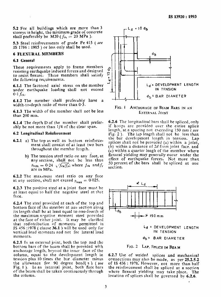
FIG. 1 ANCHORAGE OF BEAM BARS IN AN
EXTERNAL JOINT
6.2.6 The longitudinal bars shall be spliced, only if hoops are provided over the entire splice length, at a spacing not exceeding 150 mm (see Fig. 2 ). The lap length shall not be less than the bar development length in tension. Lap splices shall not be provided (a) within a joint, tb) within a distance of 2d from joint face, and (c) within a quarter lengh of the member where flexural yielding may generally occur under the effect of earthquake forces. Not more than 50 percent of the bars shall be spliced at one section.
6.2.2 The maximum steel ratio on any face at any section, shall not exceed pmax = 0.025.
6.2.3 The positive steel at a joint face must be at least equal to half the negative steel at that face.
6.2.4 The steel provided at each of the top and bottom face of the member at anv section along its length shall be at least equal to one-fourth of the maximum negative moment steel provided at the face of either joint. It may be clarified that redistribution of moments permitted in IS 456 :I978 ( clause 36.1 ) will be used only for vertical load moments and not for lateral load moments.
t_d = DEVELOPMENT LENGTH IN TENSION
db = BAR DIAMETER 6.2.5 In an external joint, both the top and the bottom bars of the beam shall be provided with FtG. 2 LAP, SPLICE IN BEAM anchorage length, beyond the inner face of the column, equal to the development length in tension plus 10 times the bar diameter minus
6.2.7 Use of welded splices and mechanical
the allowance for 90 degree bend(.s ). ( see connect,ions may also be made, as per 25.2.5.2
Fig. 1 ). In an internal joint, both face bars of IS 456 : 1978. However, not more than half
of the beam shall be taken continuously through the reinforcement shall be spliced at a section
the column. where flexural yielding may take place. The location of splices shall be governed by 62.6.
.
3
IS 13920 : 1993
6.3 Web Reinforcement
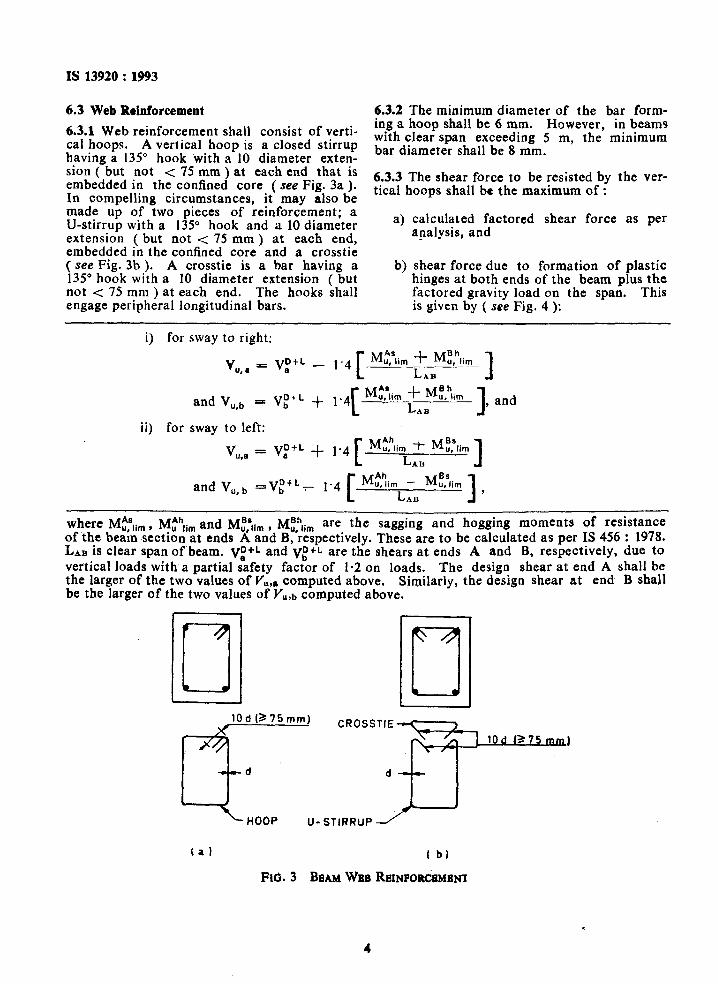
6.3.1 Web reinforcement shall consist of verti- cal hoops. A vertical hoop is a closed stirrup having a 13.5” hook with a 10 diameter exten- sion ( but not < 75 mm ) at each end that is embedded in the confined core ( see Fig. 3a ). In compelling circumstances, it may also be made up of two pieces of reinforcement; a U-stirrup with a 135” hook and a 10 diameter extension ( but not c 75 mm ) at each end, embedded in the confined core and a crosstie ( see Fig. 3b ). A crosstie is a bar having a 135” hook with a 10 diameter extension ( but not < 75 mm ) at each end. The hooks shall engage peripheral longitudinal bars.
6.3.2 The minimum diameter of the bar form- ing a hoop shall be 6 mm. However, in beams with clear span exceeding 5 m, the minimum bar diameter shall be 8 mm.
6.3.3 The shear force to be resisted by the ver- tical hoops shall be the maximum of :
a) calculated factored shear force as per analysis, and
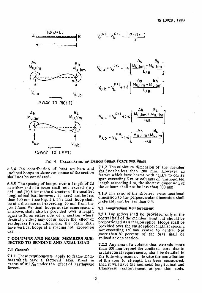
b) shear force due to formation of plastic hinges at both ends of the beam plus the factored gravity load on the span. This is given by ( see Fig. 4 ):
i) for sway to right:
V,, YC Vi+‘ e 1’4 _-._z- _‘_-- C
M uAslim f M: hlim L 1
and Vu,b - VF’ ‘ + 1.41: Mt,*ii, -I- *G,” ‘iim
LAB * 1, and
ii) for sway to left:
V “,(I = B vD+L + 1.4 [ M$h,i;t M::ii, ]
and V,,b =VisL~ 1’4 c
M?,?i, + ME,‘ii, L I
, *II
where Mt,*li, , Mthfi, and M,BI:t,,, , Mfh,i, are the sagging and hogging moments of resistance of the beam section at ends A and B,‘respectively. These are to be calculated as per IS 456 : 1978. LAB is clear span of beam. Vt+L and VE*L are the shears at ends A and B, respectively, due to ver’tical loads with a partial safety factor of 1.2 on loads. the larger of the two values of Vu,r, computed above.
The design shear at end A shall be Similarly, the design shear at end B shall
be the larger of the two values of Vu,b computed above.
I 1 ,
L HOOP U-STIRRUP -/
(aI I b)
Fib. 3 BEAM WEB RE~NFORCBMBNX
4
1s 13920 : 1993
t V t
u,a “u,b
tSWAYG,GtiT)
Ah Rii M u,lim Mu, lim
t vu.a
t Vu,b .
” WL = vi+L = 1.2 to+ L) a 2
4 Bh
V u,a = vi+L -1.4 Mu,lim +Mu,lim
I CAB 1 AS Bh D+L
v u. b = ‘b, +, .4 Mu,Iim + MuJim
LAB I
Ah Bs D+L
vu,a ‘Va +l.4 Mu,tim + Mu,iim
LAB 1 D+L_,.4
Ah Bs
vu,b = vb Mu, lim +Mu,lim
LAI3 I
(SWAY TD LEFT)
FIN. 4 CALCULATION OF DESIGN SHEAR FORCE FOR BEAM
6.3.4 The contribution of bent up bars and inclined hoops to shear resistance of the section shall not be considered.
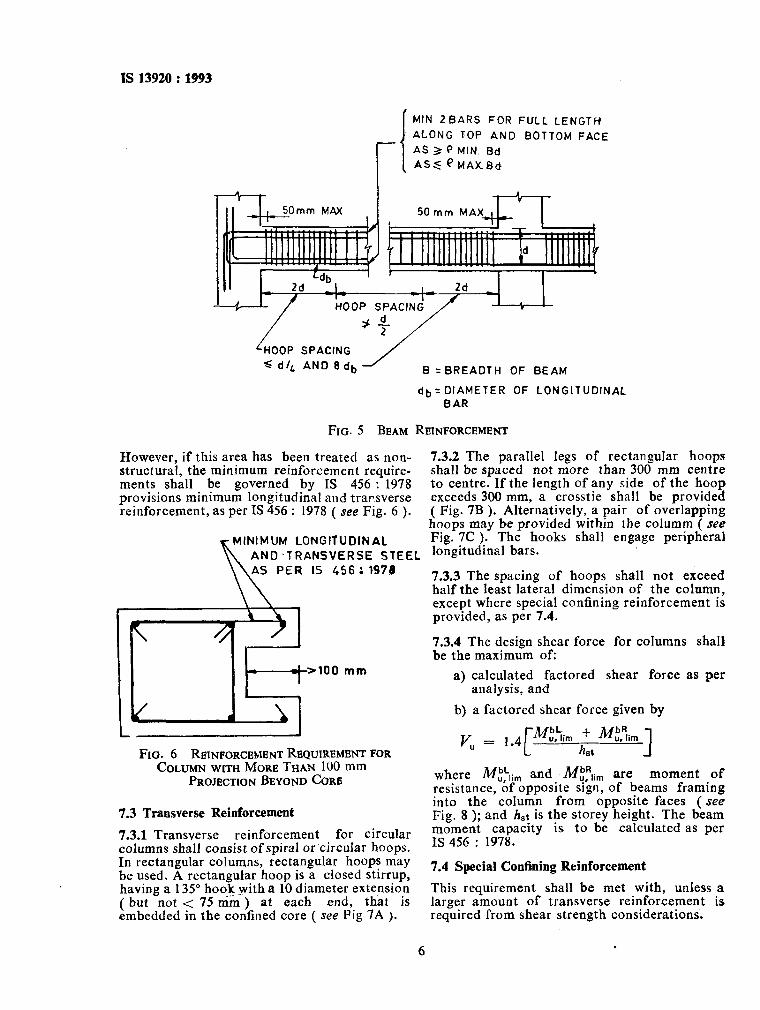
6.3.5 The spacing of hoops over a length of 2d at either end of a beam shall not exceed ( a ) d/4, and (b) 8 times the diameter of the smallest longitudinal bar; however, it need not be less than 100 mm ( see Fig. 5 ). The first hoop shall be at a distance not exceeding’ 50 mm from the joint face. Vertical hoops at the same spacing as above, shall also be provided over a length equal to 2d on either side of a section where flexural yielding may occur under the effect of earthquake forces. Elsewhere, the beam shall have vertical hoops at a spacing not exceeding d/2.
7 COLUMNS AND FRAME MEMBERS SUB- JECTED TO BENDING AND AXIAL LOAD
7.1 General
7.1.1 These requirements apply to frame mem- bers which have a factored axial stress in excess of O-1 fck under the effect of earthquake forces.
7.1.2 The minimum dimension of the member shall not be less than 200 mm. However, in frames which have beams with centre to centre span exceeding 5 m or columns of unsupported length exceeding 4 m, the shortest dimension of the column shall not be less than 300 mm.
7.1.3 The ratio of the shortest cross sectional dimension to the perpendicular dimension shall preferably not be less than 0.4.
7.2 Longitudinal Reinforcement
7.2.1 Lap splices shall be provided only in the central half of the member length. It should be proportioned as a tension splice. Hoops shall be provided over the entire splice length at spacing not exceeding 150 mm centre to centre. Not more than 50 percent of the bars shall be spliced at one section.
7.2.2 Any area of a column that extends more than 100 mm beyond the confined core due to architectural requirements, shall be detailed in the following manner. In case the contribution of this area to strength has been considered, then it will have the minimum longitudinal and transverse reinforcement as per this code,
IS 13920 : 1993
MIN ZBARS FOR FULL LENGTH
ALONG TOP AND BOTTOM FACE
AS 3 Q MIN. Bd
ASS QEtAx.Bd
II 1 HOOP SPACING ,
‘HOOP SPACING
s dl‘ AND 8db
FIG. 5 BEAM
B = BREADTH OF BEAM
db= DIAMETER OF LONGITUDINAL
BAR
REINFORCEMENT
Rowever, if this area has been treated as non- structural, the minimum reinforcement require- ments shall be governed by IS 456 : 1978 provisions minimum longitudinal and transverse reinforcement, as per IS 456 : 1978 ( see Fig. 6 ).
MINIMUM LONGITUDINAL
K AND .TRANSVERSE STEEL
\\AS PER IS 456 ; 1978
I- J
FIG. 6 REINFORCEMENT REQUIREMENT FOR COLUMN WITH MORE THAN 100 mm
PROJECTION BEYOND COW
7.3 Transverse Reinforcement
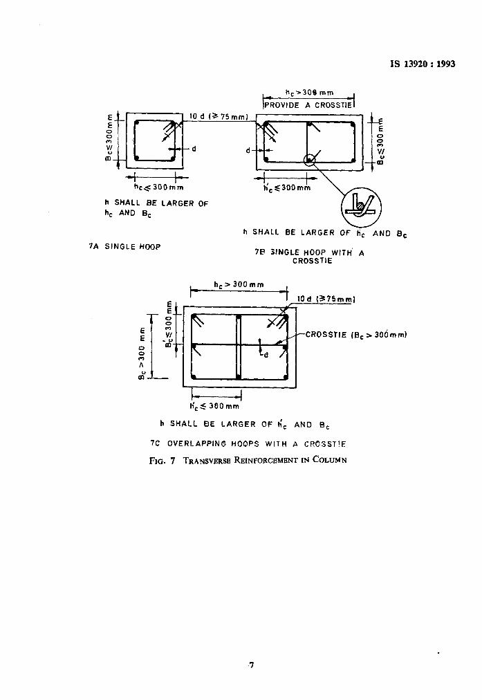
7.3.1 Transverse reinforcement for circular columns shall consist of spiral or circular hoops. In rectangular columns, rectangular hoops may be used. A rectangular hoop is a closed stirrup, having a 135” hook _with a 10 diamee;; extension ( but not < 75 mm ) at each that IS embedded in the confined core ( see iig 7A ).
7.3.2 The parallel legs of rectangular hoops shall be spaced not more than 300 mm centre to centre. If the length of any side of the hoop exceeds 300 mm, a crosstie shall be provided ( Fig. 7B ). Alternatively, a pair of overlapping hoops may be provided within the columm ( see Fig. 7C ). The hooks shall engage peripheral longitudinal bars.
7.3.3 The spacing of hoops shall not exceed half the least lateral dimension of the column, except where special confining reinforcement is provided, as per 7.4.
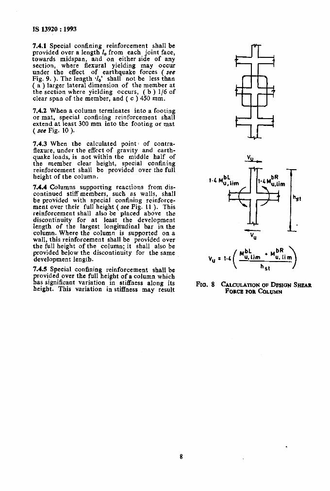
7.3.4 The design shear force for columns shall be the maximum of:
a) calculated factored shear force as per analysis, and
b) a factored shear force given by
where M,b‘,i, and M,bRlim are moment of resistance, of opposite sign, of beams framing into the column from opposite faces ( see Fig. 8 ); and h,t is the storey height. The beam moment capacity is to be calculated as per IS 456 : 1978.
7.4 Special Confining Reinforcement
This requirement shall be met with, unless a larger amount of transverse reinforcement is required from shear strength considerations.
6 .
IS 13920 : 1993
h,2309 mm
PROVIDE A CROSSTlE
il ~4 300mim
h SHALL BE LARGER OF
h, AND B,
h SHALL BE LARGER OF tic AND Bc
7A SINGLE HOOP 7B 3fNGLE HOOP WITH‘ A
CROSSTIE
h,>JOOmm
10 d (375mm)
,rCROSSflE (EC s 306 m ml
h SHALL BE LARGER OF h), AND B,
7C OVERLAPPING HOOPS WITH A CRCSSTIE
FIG. 7 TRANSVERSE REINFORCEMENT IN COLUMN
IS 13920 : 1993
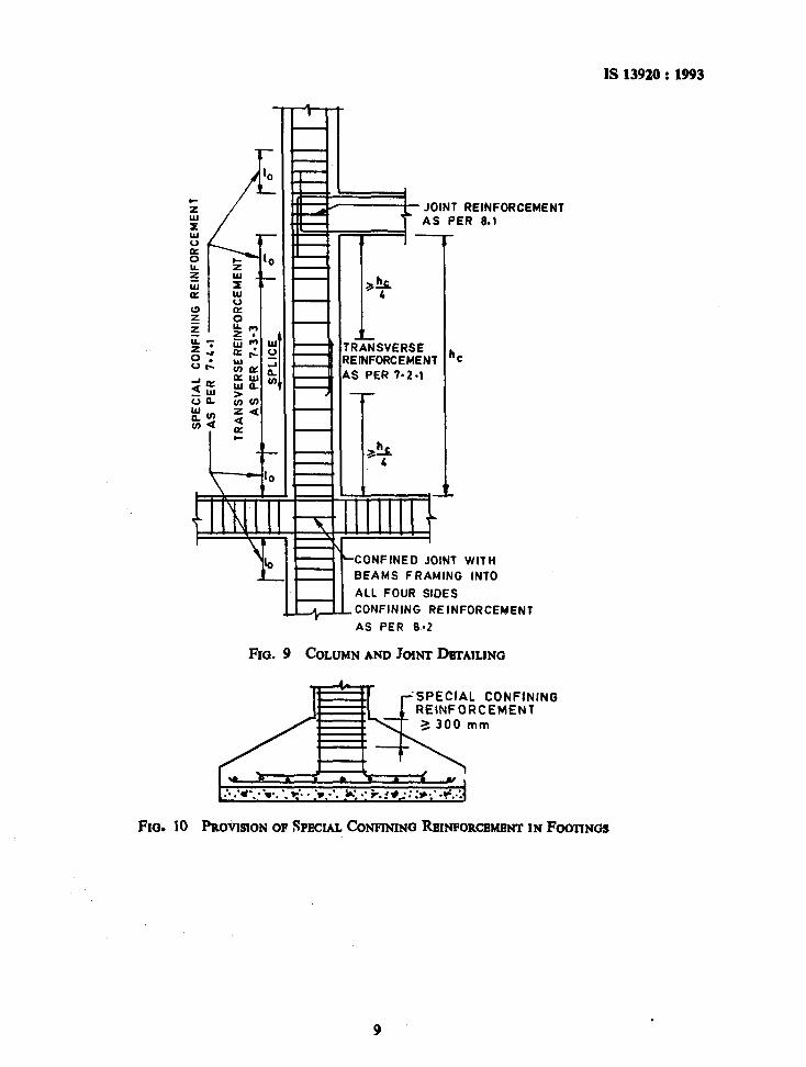
7.4.1 Special confining reinforcement shall be provided over a length I, from each joint face, towards midspan, and on either side of any section, where flexural yielding may occur under the effect of earthquake forces ( see Fig. 9. ). The length (lo* shall not be less than ( a ) larger lateral dimension of the member at the section where yielding occurs, ( b ) l/6 of clear span of the member, and ( c ) 450 mm.
7.4.2 When a column terminates into a footing or mat, special confining reinforcement shall extend at least 300 mm into the footing or mat ( see Fig. 10 ).
7.4.3 When the calculated point of contra- flexure, under the effect of gravity and earth- quake loads, is not within the middle half of the member clear height, special confining reinforcement shall be provided over the full height of the column.
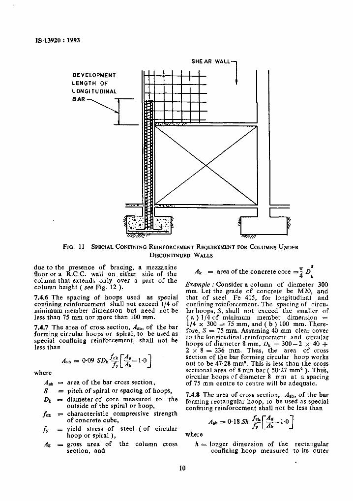
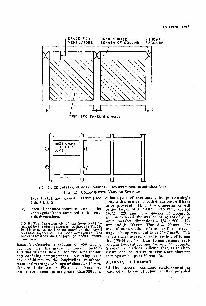
7.4.4 Columns supporting reactions from dis- continued stiff members, such as walls, shall be provided with special confining reinforce- ment over their full height ( see Fig. I1 ). This reinforcement shall also be placed above the discontinuity for at least the development length of the largest longitudinal bar in the column. Where the column is supported on a wall, this reinforcement shall be provided over the full height of the column; it shall also be provided below the discontinuity for the same development length.
7.4.5 Special confining reinforcement shall be provided over the full height of a column which has significant variation in stiffness along its height. This variation in stiffness may result
v,
%t
+I .
-vu
hlbk vu : 1.4
(
’ ‘ubRlim u.lim ,
hst 1
FIG. 8 CALCULATION OF DESIGN SHEAR FORCB POR tiLUMN
--I:
- S
PE
CIA
L
CO
NF
ININ
G
RE
INF
OR
CE
ME
NT
AS
P
ER
7-
4.1
TR
AN
SV
ER
SE
R
EIN
FO
RC
EM
EN
T
AS
P
ER
7-
3-3
I-
SP
LIC
E_
IS ,13920 : 1993
SHE AR
due to the presence of bracing, a mezzanine floor or a R.C.C. wall on either side of the Ak
column that extends only over a part of the
= area of the concrete core =$ DI
column height ( see Fig. 12 ). Example : Consider a column of diameter 300 mm. Let the grade of concrete be M20, and
7.4.6 The spacing of hoops used as special that of steel Fe 415, for longitudinal and confining reinforcement shall not exceed l/4 of minimum member dimension but need not be
confining reinforcement. The spacing of circu-
less than 75 mm nor more than 100 mm. lar hoops, S, shall not exceed the smaller of ( a ) l/4 of minimum member dimension =
7.4.7 The area of cross section, Ash, of the bar l/4 x 300 = 75 mm, and ( b ) 100 mm. There-
forming circular hoops or spiral, to be used as fore, S = 75 mm. Assuming 40 mm clear cover
special confining reinforcement, shall not be to the longitudinal .reinforcement and circular
less than hoops of diameter 8 mm, DL = 300-2 x 40 + 2 x 8 = 236 mm. Thus, the area of cross
Ash = 0.09 SD+[$- 1.0) section of the bar forming circular hoop works out to be 47.28 mm*. This is less than the cross sectional area of 8 mm bar ( 50-27 mm* ). Thus. where
A gh = S =
DB: -
f CL =
fY =
area of the bar cross section, circular hoops of diameter ‘8 mm at a’spacing of 75 mm centre to centre will be adequate.
Ag =
pitch of spiral or spacing of hoops, diameter of core measured to the
7.4.8 The area of cross section, Agh, of the bar
outside of the spiral or hoop, f orming rectangular hoop, to be used as special
characteristic compressive strength confining reinforcement shall not be less than
of concrete cube, A gh s 0.18 Sh jik Ag yield stress of steel ( of circular ~&?O]
hoop or spiral ), where
gross area of the column cross h = longer dimension of the rectangular section, and confining hoop measured to its outer
. 10
WALL
1 DEVELOPMENT
LENGTH OF
L ONGI TUDINAL
BAR
FIG. 11 SPECIAL CONFINING RBINFORCHMENT REQUIREMENT FOR COLUMNS UNDER DISCONTINUED WALLS
TS 13920 : l!J93
t- SPACE FOR UNSUPPORTED
\ SHEAR
VENTILATORS LENGTH OF COLUMN FAIL’JRE
1
PANEL/R C WALL
.
(I), 2). (3) and (4) relatively stiff columns - They attract parge seismic shear force.
FIG. 12 COLUMNS WITH VARYING STIFFNESS
face. It shall not exceed 300 mm ( see Fig. 7 ), and
AB: = area .of confined concrete core in the rectangular hoop measured to its out- side dimensions.
NOTE : The dimension 4’ of the hoop could be reduced by introducin In this case, Ak shal !!
crossties, as shown in Fig. IB. be measured as the overall
core area, regardless of the hoop arrangement. The hooks of crossties shall engage peripheral longitu- dinal bars.
Example : Consider a column of 650 mm x 500 mm. Let the grade of concrete be M20 and that of steel Fe 415,. for the longitudinal and coufining reinforcement. Assuming clear cover of 40 mm to the longitudinal reinforce- ment and rectacgular hoops of diameter 10 mm, the size of the core is 590 mm x 440 mm. As both these dimensions are greater than 300 mm,
either a pair of overlapping hoops or a single hoop with crossties, in both directions, will have to be provided. Thus, the dimension ‘h’.will b&FJarrr z:(i) 59012 = 295 mm, and (ii)
. The spacmg of hoops, $, shall not exceed the smaller of (a) l/4 of mini- mum member dimensions = l/4 x 500 = 125 mm, and (b) 100 mm. Thus, S = 100 mm. The area of cross section of the bar forming rect- angular hoop works out to be 64.47 mm*. This is less than the area of cross section of 10 mm bar ( 78.54 mm* ). Thus, 10 mm diameter rect- angular hoops at 100 mm c/c will be adequate. Similar calculations indicate that, as an alter- native, one could also provide 8 mm diameter rectangular hoops at 70 mm c/c.
8 JOINTS OF FRAMES
8.1 The special confining reinforcement as required at the end of column shall be provided
.
11
IS 13920 : 1993
through the joint as well, unless the joint is confined as specified by 8.2.
8.2 A joint which has beams framing into all vertical faces of it and where each beam width is at least 3/4 of the column width, may be provided with half the special confining reinfor- cement required at the end of the column. The spacing of hoops shall not exceed 150 mm.
9 SHEAR WALLS
9.1 General Requirements
9.1.1 The requirements of this section apply to the shear walls, which are part of the lateral force resisting system of the structure.
9.1.2 The thickness of any part of the wall shall preferably, not be less than 150 mm.
9.1.3 The effective flange width, to be used in the design of flanged wall sections, shall be assumed to extend beyond the face of the web for a distance which shall be the smaller of (a) half the distance to an adjacent shear wall web, and (b) l/IO th of the total wall height.
9.1.4 Shear walls shall be provided with reinfor- cement in the longitudinal and transverse
-directions in the plane of the wall. The minimum reinforcement ratio shall be 0.002 5 of the gross area in each direction. This reinforcement shall be distributed uniformly across the cross section of the wall.
9.1.5 If the factored shear stress in the wall exceeds 0.25 dfz or if the wall thickness exceeds 200 mm, reinforcement shall be provided in two curtains, each having bars running in the longitudinal and transverse directions in the plane of the wall.
9 1.6 The diameter of the bars to be used in any part of the wall shall not exceed l/lOth of the thickness of that part.
9.1.7 The maximum spacing of reinforcement in either direction shall not exceed the smaller of I&, 3 tw, and 450 mm; where Zw is the horizon- tal length of’the wall, and tw is the thickness of the wall web.
9.2 Shear Strength 9.2.1 The nominal shear stress, r,,, shall be calculated as:
Vll *v = tw
where
VU = factored shear force, tw = thickness of the web, and d w= effective depth of wall section. This
may by taken as 0.8 I, for rectangular sections.
9.2.2 The design shear strength of concrete, Q, shall be calculated as per Table 13 of IS 456 : 1978.
9.2.3 The nominal shear stress in the wall, rv, shall not exceed Q, maX, as per Table 14 of IS 456 : 1978.
9.2.4 When Tv is less than 7Fc shear reinforce- ment shall be provided in accordance with 9.1.4 9.1.5 and 9.1.7.
9.2.5 When Tv is greater than Q, the area of horizontal shear reinforcement, At,, to be provided within a vertical spacing. S,, is given by
V US = @87fy A, 4v &
where Vus = ( Vu - 7c tw dw ), is the shear force to be resisted by the horizontal reinforcement. However, the amount of horizontal reinforce- ment provided shall not be less than the mini- mum, as per 9.1.4.
9.2.6 The vertical reinforcement, that is uniformly distributed in the wall, shall not be less than the horizontal reinforcement calcul- ated as per 9.2.5.
9.3 Flexural Strength
9.3.1 The moment of resistance, MUv, of the wall section may be calculated as for columns subjected to combined bending and axial load as per IS 456 : 1978. The moment of resistance of slender ,rectangular shear wa!l section with uniformly distributed vertical reinforcement is given in Annex A.
9.3.2 The cracked flexural strength of the wall section should be greater than its untracked flexural strength.
9.3.3 In walls that do not have boundary elements, vertical reieforcement shall be con- centrated at the ends of the wall. Each con- centration shall consist of a minimum of 4 bars of 12 mm diameter arranged in at least 2 layers.
9.4 ‘Boundary Elements
Boundary elements are portions along the wall edges that are strengthened by longitudinal and transverse reinforcement. Though they may have the same thickness as that of the wall web it is advantageous to provide them with greater thickness.
9.4.1 Where the extreme fibre compressive stress in the wall due to factored gravity loads plus factored earthquake force exceeds 0*2f,k, boundaty elements shall be provided along the vertical boundaries of walls. The boundary
12 .
kishan naik
Highlight
,elements may be discontinued where the calcu- lated compressive stress becomes less than 0. I sfck. The compressive stress shall be calculated using a linearly elastic model and gross section properties.
9.4.2 A boundary element shall have adequate axial load carrying capacity, assuming short column action, so as to enable it to carry an axial compression equal to the sum of factored gravity load on it and the additional compres- sive load induced by the seismic force. The latter may be calculated as:
Mu - Mw C ‘W
where
Mu =
Mm =
cw -
factored design moment on the entire wall section, moment of resistance provided by distributed vertical reinforcement across the wall section, and center to center distance between the boundary elements along the two vertical edges of the wall.
9.4.3 If the gravity load adds to the strength of the wall, its load factor shall be taken as 0.8.
9.4.4 The percentage of vertical reinforcement in the boundary elements shall not be less than O-8 percent, nor greater than 6 percent. In order to avoid congestion, the practical upper limit would be 4 percent.
9.4.5 Boundary elements, where required, as per 9.4.1, shall be provided throughout their height, with special confining reinforcement, as per 7.4.
9.4.6 Boundary elements need not be provided, if the entire wall section is provided with special confining reinforcement, as per 7.4.
9.5 Coupled Shear Walls
9.5.1 Coupled shear walls shall be connected by ductile coupling beams. If the earthquake induced shear stress in the coupling beam exceeds
0.1 Is 4fT D
where Is is the clear span of the coupling beam and D is its overall depth, the entire earthquake induced shear and flexure shall, preferably, be resisted by diagonal reinforcement.
9.5.2 The area of reinforcement to be provided along each diagonal in a diagonally reinforced coupling beam shall be:
A VII ri - 1.74fr sin a
Is 13920 : 1993
where V,, is the factored shear force, and a is the angle made by the diagonal reinforcement with the horizontal. At least 4 bars of 8 mm diameter shall be provided along each diagonal. The reinforcement along each diagonal shall be enclosed by special confining reinforcement, as per 7.4. The pitch of spiral or spacing of ties shall not exceed 100 mm.
9.5.3 The diagonal or horizontal bars of a coupling beam shall be anchored in the adjacent walls with an anchorage length of 1.5 times the develapment length in tension.
9.6 Openings in Walls
9.6.1 The shear strength of a wall with openings should be checked along critical planes that pass through openings.
9.6.2 Reinforcement shall be provided along the edges of cpenings in walls. The area of the vertical and horizontal bars should be such as to equal that of the respective interrupted bars. The vertical bars should extend for the full storey height. The horizontal bars should be provided with development length in tensron beyond the sides of the opening.
9.7 Discontinuous Walls
Columns supporting discontinuous walls shall be provided with special confining reinforcement, as per 7.4.4.
9.8 Construction Joints
The vertical reinforcement ratio across a hori- zontal construction joint shall not be less than:
0.92
( P”
fv TV--
A&! >
where T,, is the factored shear stress at the joint, P, is the factored axial force ( positive for compression ), and Ae is the gross cross sectional area of the joint.
9.9 Development, Splice and Anchorage Requirement
9.9.1 Horizontal reinforcement shall be ancho- red near the edges of the wall or in the confined core of the boundary elements.
9.9.2 Splicing of vertical Sexural reinforcement should be avoided, as far as possible, in regions where yielding may take place. This cone of flexural yielding may be considered to extend for a distance of JW above the base of the wall or one sixth of the wall height, whichever is more. However, this distance need not be greater than 2 fW. Not more than one third of this vertical reinforcement shall be spliced at such a section. Splices in adjacent bars should be staggered by a minimum of 600 mm.
.
13
kishan naik
Highlight
1s 13920 : 1993
9.9.3 Lateral ties shall be provided around 9.9.4 Welded splices and mechanical eonnec- lapped spliced bars that are larger than 16 mm tions shall confirm to 25.2.5.2 of IS 456 : 1978. in diameter. The diameter of the tie shall not However, not more than half the reinforcement be less than one fourth that of the spliced bar shall be spliced at a section, where flexural nor less than 6 mm. The spacing of ties shall yielding may take place. not exceed 150 mm center to center.
ANNEX A
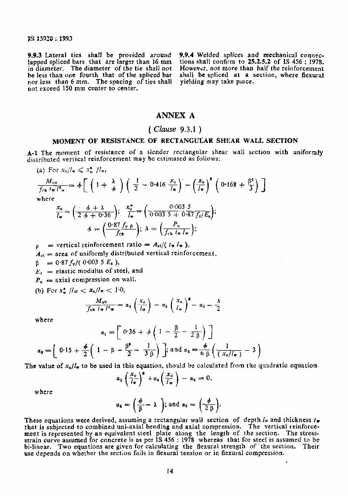
( Clause 9.3.1 ) MOMENT OF RESISTANCE OF RECTANGULAR SHEAK WALL SECTION
A-l The moment of resistance of a slender rectangular shear wall section with uniformly distributed vertical reinforcement may be estimated as follows:
(a) For xo/lw Q x’, /Iw,
where
p = vertical reinforcement ratio
o-003 5
A St = area of uniformly distributed vertical reinforcement,
P = 0.87&,/( 0.003 5 EB ), Es = elastic modulus of steel, and
P” = axial compression on wall.
(b) For x; /&v < x&i < 1.0,
where
a1 = 0*36++ I -$- & )3
a2 = I_
O.lS+$- 1-e-g- &- )I
The value of x,/l,, to be used in this equation, should be calculated from the quadratic eqvation
where
CL, = ($-A );andaa= ($-).
These equations were derived, assuming a rectangular wall section of depth 1~ and thickness tw that is subjected to combined uni-axial bending and axial compression. The vertical reinforce- ment is represented by an equivalent steel plate along the length of the section. The stress- strain curve assumed for concrete is as per IS 456 : 1978 whereas that for steel IS assumed to be bi-linear. Two equations are given for calculating the flexural strength of the section. Their use depends on whether the section fails in flexural tension or in flexural compression.
DR K. G. BHATIA DR C. KAMESHWARA RAO ( Aiternute ) SHRI A. K. SINGH ( Alternate)
SHRI S. C. BHATIA DR B. K. RASTOGI ( Alternate )
Da A. R. CHANDRASEKARAN
DR BRIIESH CHANDRA ( AIfernnte ) Da B. V. K. LAVANIA ( Alternate )
DR S. N. CHATTERJFE SHRI S. K. NAQ ( Alternate )
SHRI K. 4’. CHAUBAL Da B. K. PAUL ( Alternate )
Da A. V. CHUMMAR DR S. K. KAUSHIK ( Alternate )
DIRECTOR EMBANKMENT ( N 8~ W ) DIRECTOR CMDD ( NW & S ) ( Afternate
DIRECTOR STANDARDS ( B 8r S ), ‘RDSO JOINT DIRECTOR STANDARDS ( B & S )
CB-I. RDSO, LUCKNOW ( Alternate ) KUMARI E. DIVATIA
SHRI C. R. VENKATPSHA ( Alternate ) SHRI I. D . GUPTA
SHRI J. G. PADALE ( Alternate ) SHRI V. K. K~LKARNI
SHRI P. C. KOTESWARA RAO ( Akrnute ) SHRI V. KUMAR
SHRI R. S. BAJAJ ( jilternah ) SHRI M. Z. KURIEN
SHRI K. V. SUBRAMANIAN ( Alternate )
I
Indian-Roads Congress, New Delhi
Bharat Heavy Electricals Ltd. New Delhi
National Geophysical Research Institute ( CSIR ), Hyderabad
Department cf Earthquake Engineering, University of Roorkee. Roorkee
Indian Meterological Department, New Delhi
North Eastern Council, Shillong
Indian Society of Earthquake Technology, Roorkec
Central Water Commission ( ERDD ), New Delhi I Railway Board, Ministry of Railways
SHR~ A. K. LAL SHRI T. R. BHATIA ( Alternate )
SHRI S. K. MITTAL SHRI S. S. NARANG SHRI A. D. NARIAN
SHRI 0. P. AGGARWAL ( Alternate ) SHRI P. L. NARULA
SHRI A K. SRIVASTAVA ( Afternate ) RESEARCH OFFICFR DR D. SENGUPTA
SHRI R. K. GROVER ( Alternate ) DR R. D. SHARMA
SHR~ U. S. P. VERMA ( Alternate ) COL R. K. SINGH
Geological Survey of India, Calcutta
Irrigation Departmeot, Govt of Maharashtra, Nasik Engineers India Ltd, New Delhi
Nuclear Power Corporation, Bombay
Engineer-in-Chief’s Branch, Army Headquarters, New Delhi 1,~.COL B.D. BHATTOPADHYAYA (Alternate)
DR P. SRJNIVASLJLU Da N. LAKSHMANAN ( Alternate )
Structural Engineering Research Centre ( CSlR ), Madras
SUPERINTENDING ENGINEER (D) EXECUTIVE ENGINEER (D) II ( Alternate )
Central Public Works Department, New Delhi
DR A. N. TANDON In personal capacity ( B-7150 Safdarjung Development Area,
SHR~ J. VENKATARAMAN, New Delhi )
Director ( Civ Bngg ) Director General, BIS ( Ex-offjccio Member)
National Hydro-Electric Power Corporation Ltd, New Delhi
Central Water & Power Research Station, Pune
Department of Atomic Energy, Bombay
National Thermal Power Corporation Ltd, New Delhi
Tata Consulting Engineers, Bombay
National Buildings Organization, New Delhi .
Central Building Research Institute, Roorkee Central Water Commission ( CMDD ), New Delhi Ministry of Transport, Department of Surface Transport
( Roads Wing ), New Delhi
Secretary SHRI S. S. SETHI
Director ( Civ Engg ), BIS
( Continued on pugs 16 )
1s
IS 13920 : 1993
( Conrinuedfrom page 15 )
Earthquake Resistant Construction Subcommittee, Convener
DR A. S. ARYA
Representing
( 72/6 Civil Lines, Roorkee )
Members SHRIN.K.BHATTACHARYA SHRI B. K CHAKRABORTY
!&RI D. P. SIN~H ( AItermte )
SHRI D. N. GHOSAL DR SUDHIR K. JAIN
DR A. S. R. SAI ( Altwnute )
SHRI M. P. JAISINQH
JOINT DIRECTOR STANDARDS ( B & S ) CB-1 ASSISTANT DIRECTOR ( B 8t S ), CB-1
( Alternate )
SHRI V. KAPUR
SHRI .V. K. KAPOOR ( Alterate )
SHRI hp. KUNDU
SHRI A. K. LAL Soar T. R. BHATIA ( Alternate )
DR B. C. MATHUR
Da ( SHRIMATI ) P. R. Bose ( Alternate )
$HRI.G. M. SHOUNTHU
?R P. SRINNWIJLU Da N. LAKSHMANAN ( Alternote )
SHM SUBRATA CHAKRAVARTY
SUPERINTENDING ENQIN~ER ( DIISIQN )
CED39: 1
Engineer-in-Chief% Branch, New Delhi Housing and Urban Development Corporation, New Delhi
North Eastern Council, Shilloog Indian Institute of Technology, Kaopur
Central Buildings Research Institute. Roorkee Railway Board ( Ministry of Railways )
P&taWorks Department, Government of Hhoachal Pradesh,
Hindustao Prefab Limited, New Delhi National Buildings Organization, New Delhi
U~~o~i;; of Rocrkee, Department of Earthquake Engineering,
Public Works Department, Jammu & Kashmir Structural Engineering Research Ceotre ( CSIR ), Madras
Public Works Department, Government of Assam, Gauhati Publiog Works Department, Government of Gujrat
SUPPRINTBNDINO SURVEYOR OF WORKS SUPERINTENDENCY ENCHN~ER (D) ( 1
NDZ ) Central Public Works Department, New Delhi ltemu~e )
16
Hureau of Indian Standards
BIS is a statutory institution established under the Bureau #Indian Standards Act, 1986 to promote harmonious development of the activities of standardization, marking and quality certification of goods and attending to connected matters in the country.
Copyright
BlS has the copyright of all its publications. No part of these publications may be reproduced in any form without the prior permission in writing of BIS. This does not preclude the free use, in the course of implementing the standard, of necessary details, such as symbols and sizes, type or grade designations. Enquiries relating to copyright be addressed to the Director (Publications), BIS.
Review of Indian Standards
Amendments are issued to standards as the need arises on the basis of comments. Standards are also reviewed periodically; a standard along with amendments is reaffirmed when such review indicates that no changes are needed; if the review indicates that changes are needed, it is taken up for revision. Users of Indian Standards should ascertain that they are in possession of the latest amendments or edition by referring to the latest issue of ‘BIS Handbook’ and ‘Standards Monthly Additions’.
This Indian Standard has been developed from Dot : No. CED 39 ( 5263 )
Amendments Issued Since Publication
Amend No. Date of Issue Text Affected
BUREAU OF INDIAN STANDARDS
Headquarters:
Manak Bhavan, 9 Bahadur Shah Zafar Marg, New Delhi 110002 Telephones : 323 01 31,323 83 75,323 94 02
Regional Offices :
Telegrams : Manaksanstha (Common to all offices)
Telephone
Central :
Eastern :
Northern :
Southern :
Western :
Branches :
Manak Bhavan, 9 Bahadur Shah Zafar Marg NEW DELHI 110002
l/14 C. I.T. Scheme VII M, V. I. P. Road, Maniktola CALCUTTA 700054
Printed at Dee Kay Printers, New Delhi-l 10015, India.
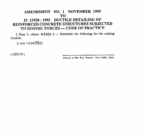
AMENDMENT NO. 1 NOVEMBER 1995 TO
IS 13920 : 1993 DUCTILE DETAILING OF REINFORCED CONCRETE STRUCTURES SUBJECTED
TO SEISMIC FORCES - CODE OF PRACTICE
[ Page 3, clause 6.2.1(b) ] - Substitute the following for the existing formula:
‘p min= 0.24@&'fy
(CED39) Printed at Dee Kay Printers, New Delhi, India
AMENDMENT NO. 2 MARCH 2002TO
IS 13920:1993 DUCTILE DETAILING OF REINFORCEDCONCRETE STRUCTURES SUBJECTED TO SEISMIC
FORCES — CODE OF PRACTICE
( Page 1, clause 1.1.1) —Substitute the following for the existing
‘1.1.1 Provisions of this code shall be adopted in all reinforced concretestructures which are located in seismic zone III, IV or V.’
( Page 3, clause 5.2, line 3 ) — Delete the word ‘preferably’.
( Page 3, c[ause 5.3 ) — Insert the following at the end of the clause:
‘However, high strength deformed steel bars, produced by the thermo-mechanical treatment process, of grades Fe 500 and Fe 550, having elongationmore than 14.5 percent and conforming to other requirements of IS 1786: 1985may also be used for the reinforcement.’