Disclosure to Promote the Right To Information Whereas the Parliament of India has set out to provide a practical regime of right to information for citizens to secure access to information under the control of public authorities, in order to promote transparency and accountability in the working of every public authority, and whereas the attached publication of the Bureau of Indian Standards is of particular interest to the public, particularly disadvantaged communities and those engaged in the pursuit of education and knowledge, the attached public safety standard is made available to promote the timely dissemination of this information in an accurate manner to the public. इंटरनेट मानक “!ान $ एक न’ भारत का +नम-ण” Satyanarayan Gangaram Pitroda “Invent a New India Using Knowledge” “प0रा1 को छोड न’ 5 तरफ” Jawaharlal Nehru “Step Out From the Old to the New” “जान1 का अ+धकार, जी1 का अ+धकार” Mazdoor Kisan Shakti Sangathan “The Right to Information, The Right to Live” “!ान एक ऐसा खजाना > जो कभी च0राया नहB जा सकता ह ै” Bhartṛhari—Nītiśatakam “Knowledge is such a treasure which cannot be stolen” IS 14419 (1996): Acceptance standards for radiographic examination of welds for ships - Recommendations [MTD 12: Welding Applications]
Transcript
Disclosure to Promote the Right To Information
Whereas the Parliament of India has set out to provide a practical regime of right to information for citizens to secure access to information under the control of public authorities, in order to promote transparency and accountability in the working of every public authority, and whereas the attached publication of the Bureau of Indian Standards is of particular interest to the public, particularly disadvantaged communities and those engaged in the pursuit of education and knowledge, the attached public safety standard is made available to promote the timely dissemination of this information in an accurate manner to the public.
इंटरनेट मानक
“!ान $ एक न' भारत का +नम-ण”Satyanarayan Gangaram Pitroda
“Invent a New India Using Knowledge”
“प0रा1 को छोड न' 5 तरफ”Jawaharlal Nehru
“Step Out From the Old to the New”
“जान1 का अ+धकार, जी1 का अ+धकार”Mazdoor Kisan Shakti Sangathan
“The Right to Information, The Right to Live”
“!ान एक ऐसा खजाना > जो कभी च0राया नहB जा सकता है”Bhartṛhari—Nītiśatakam
“Knowledge is such a treasure which cannot be stolen”
“Invent a New India Using Knowledge”
है”ह”ह
IS 14419 (1996): Acceptance standards for radiographicexamination of welds for ships - Recommendations [MTD 12:Welding Applications]
IS14419:1996
Indian Standard
ACCEPTANCE STANDARDS FOR RADIOGRAPHIC EXAMINATION OF WELDS FOR SHIPS -
RECOMMENDATIONS
ICS 25.160.10: 77.040.20: 47.020.10
BUREAU OF INDIAN STANDARDS MANAK BHAVAN. 9 BAHADUR SHAH ZAFAR MARG
NEW DELHI 110002
November 1996 Price Group 5
Welding Applications Sectional Committee, MTD 12
FOREWORD
This Indian Standard was adopted by the Bureau of Indian Standards, after the draft finalized by the Welding Applications Sectional Committee had been approved by the Metallurgical Engineering Division Council.
Ships are built under the surveys ofclassification societies. Classification Societies require the drawings to be submitted for approval with details of welding procedure, edge preparation, method of welding, etc.
Radiographic examination of welds at specified locations of the ship will be carried out according to the Surveyors requirements. These locations include joints of seams and butts in 0.6.L midship region, plate joints at hatch corners. random locations in the ‘aft and forword and the positions where stresses are more critical.
As a completely free weld cannot be achieved, the Classification Societies follow acceptance standards for weld defects depending upon the location based on stress levels.
The details of radiographic inspection are acceptance standards for weld defects are given in this standard.
In the preparation of this standard. assistance has been derived from ‘Rules for Non-destructive Inspe&ion of Hull Welds’, issued by American Bureau of Shipping 1975.
1.1 This standard covers the recommendations on acceptance standards for radiographic examination of welds in hull structure of surface vessels. These recommendations are also applicable for other marine structure like off-shore structures.
1.2 The provisions of this standard are applicable for both ferrous and non-ferrous materials.
2 REFERENCES
The Indian Standards listed below are necessary adjuncts to this standard :
IS No. Title
812 : 19.57 Glossary of terms relating to welding and cutting of metals
822 : 1970 Code of procedure for inspections of welds
2595 : 1978 Code of practice for radiographic testing ( Jim-t revision )
For the purpose of this standard, the definitions given is IS 812 : 1957 shall apply.
4 RADIOGRAPHIC TECHNIQUES
4.1 Method
A recognised radiographic technique as given in IS 2595 : 197X is to be followed.
4.2 Film Identification
The hull number and the location of the radiographed area are to be clearly indicated on the radiographic film.
4.3 Quality Indicators ( Penetrameters )
The acceptance standards decribed in this standard are based on radiographic procedure which yields a 2% - 2t sensitivity levelThe thickness of the image
quality indicator is not to be greater than 2 percent of the thickness of weld material. The indicator should contain series of drilled holes (usually three) and one of the holes should have a diameter twice that of the thickness of the indicator. Other types of indicators which give the same degree of sensitivity can be used. The indicator is to be placed on the source side of the weld and the indicator and hole must be clearly visible on the radiograph. For details of indicators. IS 3657 : 1978 is to be followed.
5 EXTENT OF RADIOGRAPHIC INSPECTION
The extent of radiographic inspection within the midship 0.6L of the surface vessels is to be as given by the equation :
where n=
L=
l3=
D=
n = L ( B+D )/46.5
minimum number of check points,
length of vessel in meters between perpendiculars ( LBP ),
moulded breadth in meters, and
moulded depth in meters.
6 LOCATION OF RADIOGRAPHIC INSPECTION
Intersections of butts and seams in sheer strakes, bilge strakes, deck stringer, keel plates, butts in hatch corners of main deck within 0.6L midship are to be mainly subjected to radiographic inspection. Inspection of other locations are to be carried out at the discretion of the surveyor.
7 ACCEPTANCE STANDARDS
7.1 Class A Vessels
7.1.1 Surface K3sels
Radiographicinspection of full penetration welds for all surface vessels I SW/and over. in the 0.6L midship locations indicated in 6 is to meet the requirements of Class A. Class A will also be applicable to surface vessels less than 15OMwhen the hull design of material justifies the severity level.
1
IS 14419 : 1996
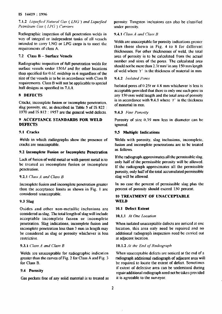
7.1.2 LiqwJed Natural Gas ( LNG ) and Liquejed Petroleum Gas ( LPG ) Carriers
Radiographic inspection of full .penetration welds in way of integral or independent tanks of all vessels intended to carry LNG or LPG cargo is to meet the requirements of class A.
7.2 Class B - Surface Vessels
Radiographic inspection of_full penetration welds for surface vessels under 15OA4 and for other locations than specified for 0.6L midship in 6 regardless of the size of the vessels is to be in accordance with Class B requirements. Class B will not be applicable to special hull designs as specified in 7.1.1.
8 DEFECTS
Cracks, incomplete fusion or incomplete penetration. slag porosity, etc, as described in Table 5 of IS 822 : 1970 and IS 812 : 1957 are the general weld defects.
9 ACCEPTANCE STANDARDS FOR WELD DEFECTS
9.1 Cracks
.Welds in which radiographs show the presence of cracks are unacceptable.
9.2 Incomplete Fusion or Incomplete Penetratiun
Lack of fusion of weld metal or with parent metal is to be treated as incomplete fusion or incomplete penetration.
9.2.1 Class .4 and Class B
Incomplete fusion and incomplete penetration greater than the acceptance limits as shown in Fig. 1 are considered unacceptable.
9.3 SIag
Oxides and other non-metallic inclusions are considered as slag. The total length of slag will include acceptable incomplete fuston or incomplete penetration. Slag indications, incomplete Rrsion and incomplete penetration less than 3 mm in length may be considered as slag or porosity whichever is less restrictive.
9.3.1 Class .4 and Class B
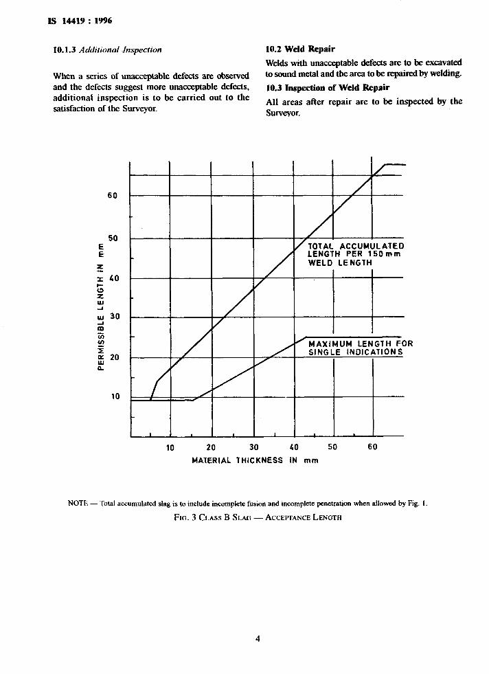
Welds are unacceptable for radiographic indication greater than the curves of Fig. 2 for Class A and Fig. 3 for Class ~B.
9.4 Porosity
Gas pockets free of any solid material is to treated as
porosity. Tungsten inclusions can also be classified under porosity.
9.4.1 Class A and Class B
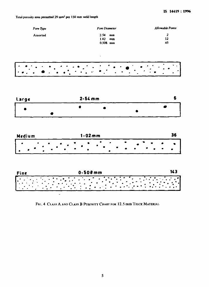
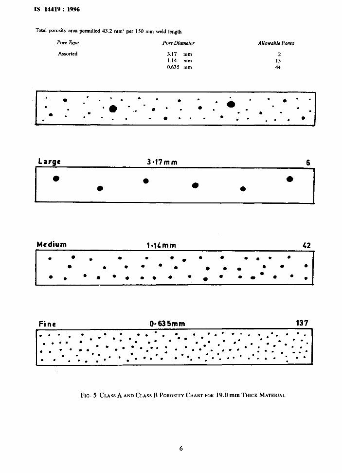
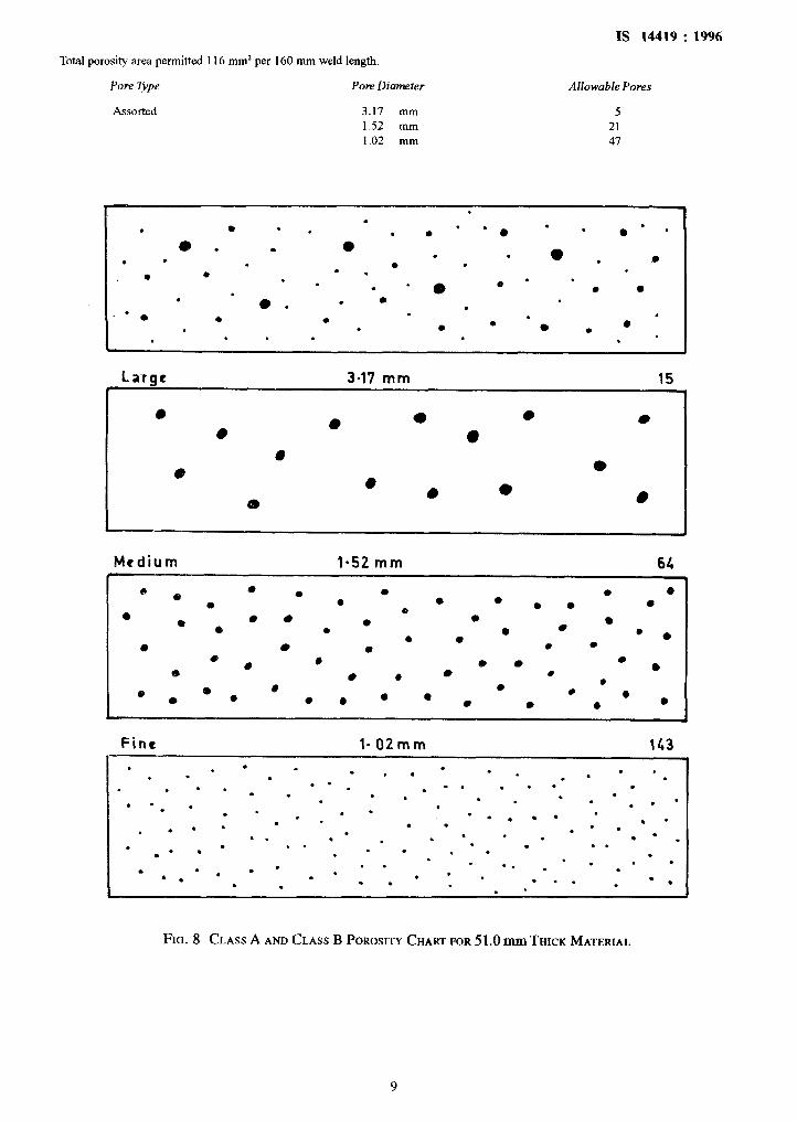
Welds are unacceptable for porosity indications greater than those shown in Fig. 4 to 8 for different thicknesses. For other thicknesses of weld. the total area of porosity is to be calculated from the actual number and sizes of the pores. The calculated area should not be more than 2.31 mm2 in any 150 mm length of weld where ‘I ’ is the thickness of material in mm
9.4.2 Isolated Pores
Isolated pores of 0.251 or 4.8 mm whichever is less is acceptable provided that there is only one such pore in any 150 mm weld-length and the total area of porosity is in accordance with 9.4.1 where ‘t ’ is the thickness of material in mm.
9.4.3 Fine Porosity
Porosity of size X1.39 mm less in diameter can be ignored.
9J Multiple Indications
Welds with porosity, slag inclusions, incomplete. fusion and incomplete penetrations are to be treated as follows.
If the radiograph approximates all the permissible slag. only half of the permissible porosity will be allowed. If the radiograph approsimates all the permissible porosity, only half of the total accumulated permissible slag will be allowed.
In no case the percent of permissible slag plus the percent of porosity should exceed 150 percent.
10 TREATMENT OF UNACCEPTABLE WELD
10.1 Defect Extent
10.1.1 .41 One Location
When isolated unacceptable defects are noticed at one location, this area only need be repaired and no additional radiograph inspection need be carried out at adjacent location.
10.1.2 ,4t the End of Radiograph
When unacceptable defects are noticed at the end of a radiograph additional radiograph of adjacent area will be required to locate the extent of defect. Sometimes if extent of defective area can be understood during repair additional radiograph need not be taken provided it is agreeable to the surveyor.
w
E 30 E
TOTAL ACCUMULATED LENGTH PER 15Omm WELD LENGTH
MAXIMUM LENGTH FOR SINGLE lNDlCATlONS
1 I I I I I
10 20 30 40 50 60 MATERIAL THICKNESS IN mm
FIG. 1 CLASS A AND CLASS B INCOMPLETE FUSION AND INCOMPLETE PENETRATION -ACCEFTANCE LENGTH
TAL ACCUMULATED LENGTH R 150mm WELD LENGTH
AXIMUM LENGTH FOR SINGLE INDICATIONS
4’
I I I 1 I I
10 20 30 40 50 60
MATERIAL THICKNESS IN mm
NOTE - Total accumulated slag is to include incomplete fusion and incomplete penetration when allowed by Fig. I.
FIG. 2 CLASS A SLAM -ACCP~ANCE LENGTH
Is 14419 : 1996
10.1.3 Additional inspection
When a series of unacceptable defects are observed and the defects suggest more unacceptable defects, additional inspection is to be carried out to the satisfaction of the Surveyor.
10.2 Weld Repair
Welds with unacceptable defects are to be excavated to sound metal and the area to be repaired by welding.
10.3 Inspection of Weld Repair
All areas after repair are to be inspected by the Surveyor.
60
I 1 I 1 1
10 20 30 40 50 60
MATERIAL THICKNESS IN mm
NOTE - Total accumulated slag is to include incomplete fusion and incomplete penetration when allowed by Fig. 1.
FIG. 3 CLASS B SLAG - ACCEITANCE LENGTH
4
Is 14419 : 19%
Total porosity mea pemuttd 29 mm* per 150 mm weld length
Pow Type
Assorted
Porn Dieter Allowable Ponzs
2.54 mm 2 1.02 mm 12 0.508 mm 45
MIdilJtYl la02mm 36
Fine 0s508mm 143 .cg . -.B l . * :. *.a.*. . l . .-. . . . . l . .
FIG. 4 CLASS A AND CLASS B POROSITY CHART FOR 12.5 mm THICK MATERIAL
Is 14419 : 1996
Total porosity area permitted 43.2 mm* per 150 mm weld length
Pore Type POW Diameter
Assorted 3.17 mm 1.14 mm 0.635 mm
Allowable Pores
2
13
44
. l _= :.
. . l .
.
. : .* . * l - _*** .- . : ‘, *- ._ _ . -0 _. . _ . . . l l . l 0.. . l .- l
r
large 3.17mm 6 I
l 0 l
Fine O-635mm 137 c l .*. l
. . . -0 . . . .
0.. ..*. . . . . . . l 0. l . . ’
. . l * . l .
l . ..* . . . ,* l . . ..*
. . .‘*. . .
.e - l . . . = . ‘..‘. l *. .’ : ..- . . . . .
* l
‘. 09.0 . . . . . . ..=. :*...*... ..* :. . . /.=
FIG. 5 CLASS A AND CLASS B POROSITY CHART FOR 19.0 mm THICK MATERIAL
6
Is 14419 : 1996
Total porosity area permitted 58.1 mm2 per I50 mm-weld length
Pore Type
Assorted
Porn Diameter
3.17 mm 1.27 mm 0.762 mm
Allowable Pores
2
17 45
Large 3a17 mm 7 l
M cdium 1 l 27mm 46
O-762 mm
. . . a
. . .
.
l . .
. . l
. . . 0.0
. 9 l . . . . . l .
. . . . . l
. .
l l * l .
. . . . . .
. . .* . . l
l .:* .
. . ..#
. . l . . .
’ . . . l a
l
. l _. . . . l * . . l .
@ . . . .
. . l
. . l l ** . . . . . . l *a . .
. l . . -. l l .
FIG. 6 CLASS A AND CLASS B POROSITY CtImr FOR 25.5 mm THICK MATERIAL
7
Is 14419 : 1996
Total porosity area pem&ed 87.1 mm2 per 150 mm weld length
Pore Type POE Dimneter
Assorted 3.17 mm
1.40 lml 0.89 mn
Allowable Ponzs
4 18 45
&
0 . .
. l l o . . . . 0 .
l . .
. .
. . 0
. . . . . . . . . . l * . 0
0 . 0
l . l .
0 . 0 l - 0 . . - . . . . . . . . w
Large 3-17mm 11 I
Medium t
l-40 mm 57
Fine 0*89mm 140
l . . . .
. l
. .
. l . . - . .
l 0. .
- . l
.
. . -
. . . . e -
. . .-•. .- l
. m
.
.
.
. l . . . . l
.
. -. . _
* . . . . . .
. l
- . .
-- m.* . . . . .
. . l . . .
. . . l l
. . e l .
. . .
. l . l -
.
. . -
- l .
. . .
I
FIG. 7 CLASS A AND CLASS B POROSITY CHART FOR 38.0 mmTHlCK MATERIAL
8
IS 14419 : 1996
Total porosity area permitted 116 mm* per 160 mm weld length.
Pore Type Pore Diameter
Assorted 3.17 mm
1.52 mm
1.02 mm
Allowable Pores
5
21 47
l
. 8 l . .
. .
*. l . 0’ ’
(I,. . 0 . . . * 0
e . 0 . . .
. b * l . . .
. . - 0 . l
0 0 . . 0. l l
. .
. l l .
0 . .
. . l . . .
0 l
. . . . . .
La1ge 3.17 mm 15
Medium l-52 mm 62
0 e e 0 0 0 Q 0 0 0 l 0 0 0 0
0 e 0 l 0
0 l
0 0 0 l 0 0 0
0 0 0
0 *
0 e
0 0 e 0 0 &
l 0 0 0
0
0 5 I 0 0 0 e 0 @ l Q 0 l l l 0
Fine 1.02mm 143 . . ’ . - * . l l . . . . . . . ’ .
. . l . l - . . . . l l . - . ’ : . .
. l . l . . .
. l . . ’
. - ’ . l
. l . . l l
. . . -
. * l
. . . . .* ’
. . . . . . ’ . l l . . l . . l
. . . . . . . ’ - . . . . . l . . .
. . l . l
. l
. . ** . . l . l . .
. . - . l . . . . l .
FIG. 8 CLASS A AND CLASS B POROSITY CHART FOR 5 1 .O mm THICK MATERIAL
9
Bureau of Indian Standards
BIS is a statutory institution established under the Bureau oflndian StandardsAct. 1986 to promote harmonious development of the activities of standardization, marking and quality certification of goods and attending to connected matters in the country.
Copyright
BIS has the copyright of all its publications. No part of these publications may be reproduced in any form without the prior permission in writing of BIS. This does not preclude the free use, in the course of implementing the standard, of necessary details, such as symbols and sizes, type or grade designations. Enquiries relating to copyright be addressed to the Director (Publications), BIS.
Review of Indian Standards
Amendments are issued to standards as the need arises on the basis of comments. Standards are also reviewed periodically; a standard along with amendments is reaffirmed when such review indicates that no changes are needed; if the review indicates that changes are needed, it is taken up for revision. Users of Indian Standards should ascertain that they are in possession of the latest amendments or edition by referring to the latest issue of ‘BIS Handbook’ and ‘Standards : Monthly Additions’.
This Indian Standard has been developed from Dot : No. MTD 12 ( 4123 ).