Disclosure to Promote the Right To Information Whereas the Parliament of India has set out to provide a practical regime of right to information for citizens to secure access to information under the control of public authorities, in order to promote transparency and accountability in the working of every public authority, and whereas the attached publication of the Bureau of Indian Standards is of particular interest to the public, particularly disadvantaged communities and those engaged in the pursuit of education and knowledge, the attached public safety standard is made available to promote the timely dissemination of this information in an accurate manner to the public. इंटरनेट मानक “!ान $ एक न’ भारत का +नम-ण” Satyanarayan Gangaram Pitroda “Invent a New India Using Knowledge” “प0रा1 को छोड न’ 5 तरफ” Jawaharlal Nehru “Step Out From the Old to the New” “जान1 का अ+धकार, जी1 का अ+धकार” Mazdoor Kisan Shakti Sangathan “The Right to Information, The Right to Live” “!ान एक ऐसा खजाना > जो कभी च0राया नहB जा सकता ह ै” Bhartṛhari—Nītiśatakam “Knowledge is such a treasure which cannot be stolen” IS 14673 (1999): Liquid flow measurement in open channels by weirs and flumes - Triangular profile weirs [WRD 1: Hydrometry]
Transcript
Disclosure to Promote the Right To Information
Whereas the Parliament of India has set out to provide a practical regime of right to information for citizens to secure access to information under the control of public authorities, in order to promote transparency and accountability in the working of every public authority, and whereas the attached publication of the Bureau of Indian Standards is of particular interest to the public, particularly disadvantaged communities and those engaged in the pursuit of education and knowledge, the attached public safety standard is made available to promote the timely dissemination of this information in an accurate manner to the public.
इंटरनेट मानक
“!ान $ एक न' भारत का +नम-ण”Satyanarayan Gangaram Pitroda
“Invent a New India Using Knowledge”
“प0रा1 को छोड न' 5 तरफ”Jawaharlal Nehru
“Step Out From the Old to the New”
“जान1 का अ+धकार, जी1 का अ+धकार”Mazdoor Kisan Shakti Sangathan
“The Right to Information, The Right to Live”
“!ान एक ऐसा खजाना > जो कभी च0राया नहB जा सकता है”Bhartṛhari—Nītiśatakam
“Knowledge is such a treasure which cannot be stolen”
“Invent a New India Using Knowledge”
है”ह”ह
IS 14673 (1999): Liquid flow measurement in open channelsby weirs and flumes - Triangular profile weirs [WRD 1:Hydrometry]
Indian Standard
LIQUID FLOW MEASUREMENT IN OPEN CHANNELS BY WEIRS AND FLUMES - TRIANGULAR
PROFILE WEIRS
ICS 17.120.0
Q BIS 1999
BUREAU OF INDIAN STANDA,RDS MANAK BHAVAN, 9 BAHADUR SHAH ZAFAR MARG
NEW DELHI 110002
May 1999 Price Group 6
Fluid Flow Measurement Sectional Committee, RVD 1
FOREWORD
This Indi a%
tandard was adopted by the Bureau of Indian Standards, after the draft finalized by the Fluid Flow Measurem t Sectional Committee had been approved by the River Valley Division Council.
Various methods are adopted for measurement of flow of water in open channels like velocity area method, slope area method, etc, depending upon the channel, flow conditions, measuring equipment etc. Triangular profile weirs are used for flow measurement in open channels under steady flow conditions. This Indian Standard on liquid flow measurement by triangular profile weirs has been prepared based on IS0 4360 : 1984 ‘Liquid flow measurement in open channels by weirs and flumes - Triangular profile weirs’ and, therefore, is technically equivalent to the IS0 Standard.
For measurement of uncertainties reference shall be made to IS0 5 168 : 1978 ‘Measurement of fluid flow- Estimation of uncertainty of a flow rate measurement’, since corresponding Indian Standard on the subject is not available as yet.
For the purpose of deciding whether a particular requirement of this standard is complied with, the final value, observed or calculated, expressing the result of a test or analysis, shall be rounded off in accordance with IS 2 : 1960 ‘Rules for rounding off numerical values (revised)‘. The number of signiftcant places retained in the rounded off value should be the same BS that of the specified value in this standard.
IS 14673 : 1999
Indian Standard
LIQUID FLOW MEASUREMENT IN OPEN CHANNELS BY WEIRS AND FLUMES - TRIANGULAR
PROFILE WEIRS
1 SCOPE
This standard specifies methods for the measurement of the flow of water in open channels under steady flow conditions using triangular profile weirs. The flow conditions considered are steady flows which are uniquely dependent on the upstream head and drowned flows which depend on downstream as well as upstream levels.
2 REFERENCES
The following standards contain provisions which through reference in this text, constitute provision of this standard. At the time of publication the editions indicated were valid. All standards are subject to revision, and parties to agreements based on this standard are encouraged to investigate the possibility of applying the most recent editions of the standards indicated below:
IS No. Title I 19 1 : 197 1 Glossary of terms and symbols used
in connection with the measurement of liquid flow with a free surface (first revision)
1192 : 198 1 Velocity area methods for measure- ment of flow of water in open channels (first revision)
9 116 : 1979 Specification for water stage recorder
(float type)
3 DEFINITIONS AND SYMBOLS
For the purpose of this Indian Standard, the definitions given in IS 119 1 shall apply. The symbols used in this Indian Standard are given in Annex A.
4 UNITS OF MEASUREMENT
The units of measurement used by this standard are seconds and metres.
5 INSTALLATION
Conditions regarding preliminary survey, selection of site, installation, the approach channel, maintenance, measurement of head, and stilling or float wells which are generally necessary for flow measurement are given in the following sub-clauses. The particular requirements for the triangular profiles weirs are given separately in 8.
5.1 Selection of Site
5.1.1 A preliminary survey shall be made of the physical and hydraulic features of the proposed site, to check that it conforms (or may be made to conform) to the requirements necessary for measurement by a weir.
5.1.2 Particular attention should be paid to the following features in selecting the site:
4
b) cl 4
e)
r)
g)
h)
j)
k)
Availability of an adequate length of chan- nel of regular cross section;
The existing velocity distribution;
The avoidance of a steep channel, if possible;
The effects of any increased upstream water level due to the measuring structure;
Conditions downstream including such in- fluences as tides, confluences with other streams, sluice gates, milldams and other controlling features which might cause sub- merged flows;
The impermeability of the ground on which the structure is to be founded, and the neces- sity for piling, grouting or other sealing-in river installations;
The necessity for flood banks to confine the maximum discharge to the channel;
The stability of the banks and the necessity for trimming and/or revetment in natural channels;
The clearance of rocks or boulders from the bed of the approach channel; and
The effect of wind; wind can have a consid- erable effect on the flow in a river or over a weir, especially when these are wide and the head is small and when the prevailing wind is in a transverse direction.
5.1.3 If the site does not possess the characteristics necessary for satisfactory measurement, the site shall be rejected unless suitable improvements are practicable.
5.1.4 If an inspection of the streani ‘shows that the existing velocity distribution is regular, then it may be assumed that the velocity distribution will remain satisfactory after the construction of a weir.
IS 14673 : 1999
51.5 If the existing velocity distribution is irregular and no other site for a gauge is feasible, due
consideration shall be given to checking the distribution after the installation of the weir and to
improving it if necessary.
5.1.6 Several methods are available for obtaining a
more precise indication of irregular velocity distribution: Velocity rods, floats or concentrations of dye can be used in small channels, the latter being useful in checking conditions at the bottom of the channel. A complete and quantitative assessment of
velocity distribution may be made by means of a current meter. Complete information about the use of current meters is given in IS 1192.
5.2 Installation Conditions
5.2.1 General
The complete measuring installation consists of an approach channel, a measuring structure and a downstream channel. The conditions of each of these
three components affect the overall accuracy of the measurements.
Installation requirements include such features as weir finish, cross-sectional shape of channel, channel roughness, influence of control device, upstream or downstream of the gauging structure.
The distribution and direction of velocity, determined by the features outlined in 51.1 have an important influence on the performance of the weir.
Once an installation has been constructed, the user
shall prevent any change which could affect the discharge characteristics.
5.2.2 Approach Channel
On all installations the flow in the approach channel shall be smooth, free from disturbance and shall have a velocity distribution as normal as possible over the cross-sectional area. This can usually be verified by inspection or measurement. In the case of natural
streams or rivers this can only be attained by having a long straight approach channel free from projections
either at the side or on the bottom. Unless otherwise specified in the appropriate clauses, the following general requirements shall be complied with:
a) The altered flow-conditions due to the con- struction of the weir might have the effect of building up shoals of debris upstream of the structure, which in time might effect the flow conditions. The likely consequential changes in the water level shall bc taken into account in the design of gauging stations.
b) In an artificial channel the cross -section shall be uniform and the channel shall be straight
2
c)
d)
4
f)
for a length equal to at least live times its breadth.
In a natural stream or river the cross-section shall be reasonably uniform and the channel shall be straight for such a length as to ensure regular velocity distribution.
If the entry of the approach channel is through a bend or if the flow is discharged into the channel through a conduit of smaller cross- section, or at an angle, then a longer length of straight approach channel may be required to achieve a regular velocity distribution.
There shall be no baffle nearer to the points of measurement than five times the maximum head to be measured.
Under certain conditions, a standing wave may occur upstream of the gauging device, for example, if the approach channel is steep. Provided this wave is at a distance of not less than 30 times the maximum head upstream, flow measurement will be feasible, subject to confirmation that a regular velocity distribu- tion exists at the gauging station.
5.2.3 Measuring Structure
The structure shall be rigid and watertight and capable of withstanding flood flow conditions without distortion and fracture. It shall be at right angles to the direction of flow and shall conform to the dimensions given in the relevant clauses.
5.2.4 Downstream of the Structure
The channel downstream of the structure is of no importance as such if the weir has been so designed that the flow is modular under all operating conditions.
A downstream gauge shall be provided to measure tailwater levels to determine when submerged flow occurs.
In the event of the possibility of scouring downstream which phenomenon may also lead to the instability of the structure, particular measure to prevent this happening may be necessary.
A crest tapping and separate stilling well shall be fitted if the weir is designed to operate in a drowned condition or if there is a possibility that the weir may drown in the future.
The latter circumstances may arise if the altered flow conditions due to the construction of the weir have the effect of building up shoals of debris immediately downstream of the structure or if river works are carried out downstream at a later date.
6 MAINTENANCE
Maintenance of the measuring structure and the
IS 14673 : 1999
approach channel is important to secure accurate continuous measurements.
It is essential that the approach channel to weirs should be kept clean and free from silt and vegetation as far as practicable for at least the distance specjfied in 5.2.2. The float well and the entry from the approach channel shall also be kept clean and free from deposits.
The weir structure shall be kept clean and free from clinging debris and care shall be taken in the process of cleaning to avoid damage to the weir crest.
7 MEASUREMENT OF HEAD
7.1 General
The head upstream of the measuring structure may be measured by a hook-gauge, point-gauge or staff-gauge where spot measurements are required, or by a recording-gauge where a continuous record is required, and in many cases it is preferable to measure heads in a separate stilling-well to reduce the effects of water surface irregularities.
The discharges given by the working equation are volumetric figures, and the liquid density does not affect the volumetric discharge for a given head provided that the operative head is gauged in liquid of identical density, If the gauging is carried out in a separate well, a correction for the difference in density may be necessary if the temperature in the well is significantly different from that of the flowing liquid. However, it is assumed herein that the densities are equal.
7.2 Stilling-Well or Float-Well
Where provided, the stilling-well shall be vertical and have a free-board of 0.6 over the maximum water level estimate to be recorded in the well.
It shall be connected to the river by an inlet pipe or slot, large enough to permit the water in the well to follow the rise and fall of head without significant delay.
The connecting pipe or slot shall, however, be as small as possible, consistent with ease of maintenance, or, alternatively, shall be fitted with a constriction to damp out oscillations due to short amplitude waves.
The well and the connecting pipe or slot shall be watertight where provided for the accommodation of the float of a level recorder, the well shall be of adequate diameter and depth to accommodate the float.
The well shall also be deep enough to accommodate any silt which may enter, without the float grounding. The float-well arrangement may include an intermediate chamber between the stilling-well and
the approach channel of similar proportions to the stilling-well to enable silt and other solids to settle out. For ease of maintenance the pipework may be valved.
For detailed description of the stilling-well (see IS 9116).
7.3 Zero Setting
A means of checking the zero setting of the head- measuring devices shall be provided, consisting of a datum related to the level of the weir.
A zero check based on the level of the water when the flow ceases is liable to serious errors from surface tension effects and shall not be used.
As the size of the weir and the head on it reduces, small errors in construction and in the zero setting and reading of the head-measuring device become of greater importance.
8 SPECIFICATION FOR THE STANDARD WEIR
8.1 Description
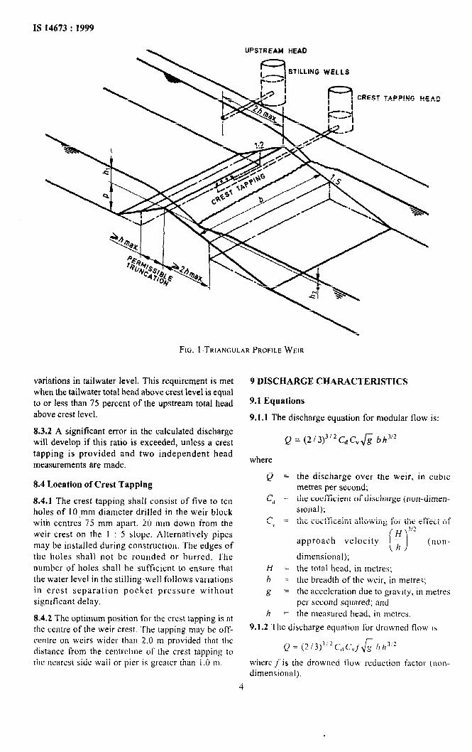
8.1.1 The weir comprises an upstream slope of 1 (vertical) to 2 (horizontal) and a downstream slope of 1 (vertical) to 5 (horizontal). The intersection of these two surfaces forms a straight line crest, horizontal and at right angles to the direction of flow in the approach channel. Particular attention shall be given to the crest itself, which shall possess a well- defined corner of durable construction. The crest may be made of pre-formed sections, carefully aligned and jointed, or may have a non-corrodible metal insert, as an alternative to in-situ construction throughout.
8.1.2 The dimensions of the weir and its abutments shall conform to the requirements indicated in Fig. I. Weir blocks may be truncated but not so much as to reduce their dimensions in plan to less than 1.0 hMuX for the 1 : 2 slope and 2.0 hMti for the I : 5 slope.
8.2 Location of Head Measurement Section
Piezometers or point-gauge stations for the measurement of head on the weir shall be located at a sufficient distance upstream from the weir to avoid the region of surface drawdown. On the other hand, they shall be close enough to the weir to ensure that the energy loss between the section of measurement and the control section on the weir shall be negligible. It is recommended that the head-measurement section shall be located at a distance equal to twice the maximum head (2 hMa,,) upsteam of the crest.
8.3 Condition for Modular Flow
8.3.1 Flow is modular when it is independent of
3
UPSTREAM HEAD
STILLING WELLS
CREST TAPPING HEAD
FIG. 1 .TRIANGULAR PROFILE WEIR
variations in tailwater level. This requirement is met when the tailwater total head above crest level is equal to or less than 75 percent of the upstream total head above crest level.
8.3.2 A significant error in the calculated discharge will develop if this ratio is exceeded, unless a crest tapping is provided and two independent head measurements are made.
8.4 Location of Crest Tapping
8.4.1 The crest tapping shall consist of five to ten holes of IO.mm diameter drilled in the weir block with centres 75 mm apart, 20 mm down from the weir crest on the 1 : 5 slope. Alternatively pipes may be installed during construction. The edges of the holes shall not be rounded or burred. The number of holes shall be sufficient to ensure that the water level in the stilling-well follows variations in crest separation pocket pressure without significant delay.
8.4.2 The optimum position for the crest tapping is at the centre of the weir crest. The tapping may be off- centrc on weirs wider than 2.0 m provided that the distance from the centrclme of the crest tapping to the nearest side wall or pier is greater than 1 .O m.
9 DISCHARGE CHARACTERISTICS
9.1 Equations
9.1.1 The discharge equation for modular flow is:
Q = (2/3)3’2CdCv& bh3’*
where
Q =
Cd =
cp =
H =
b z
g =
h -
the discharge over the weir, in cubic metres per second; the coefficient of discharge (non-dimen- sional);
the coefiiceint allowing for the effect of
H 3’2 approach velocity r,
i 1 (non-
dimensional);
the total head, in mctres; the breadth of the weir, in metres;
the acceleration due to gravity, in metres per second squared; and the measured head, in metrcs.
9.1.2 The discharge equation for drowned flow IS:
Q = (2/J) ~i2Cdc.J& Irh7’?
where J’ is the drowned flow reduction factor (non- dimensional).
4
IS 14673 : 1999
9.2 Coefficients
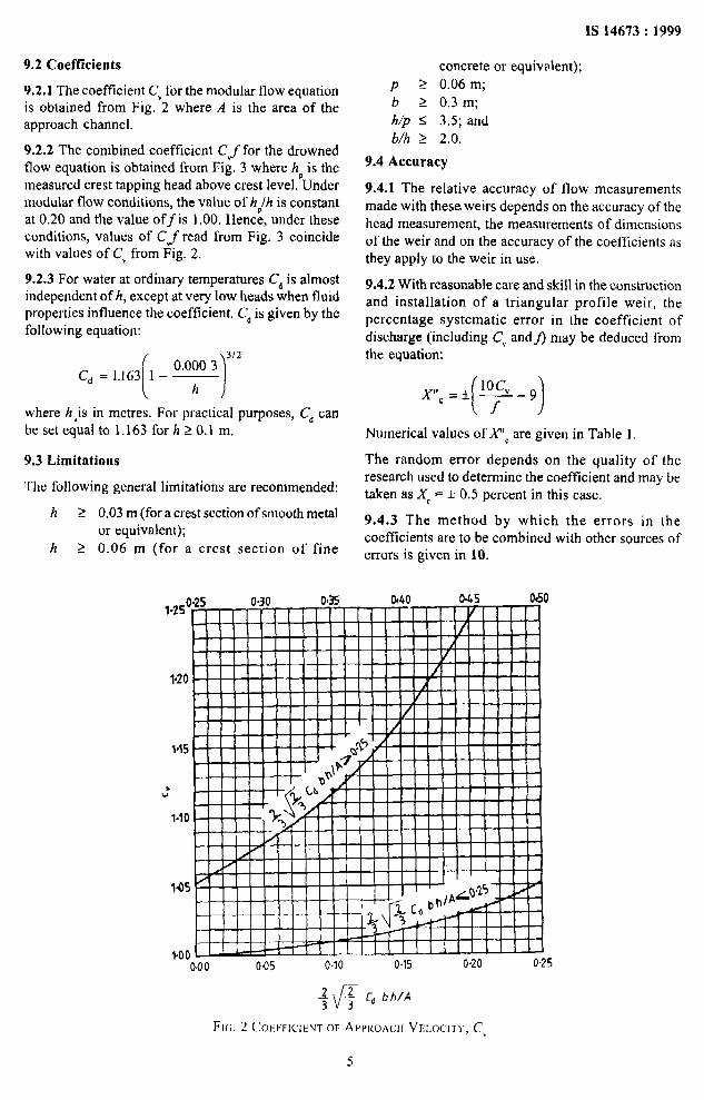
9.2.1 The coefficient CV for the modular flow equation is obtained from Fig. 2 where A is the area of the approach channel.
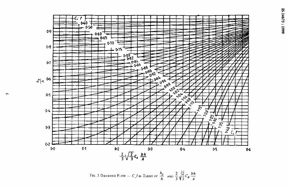
9.2.2 The combined coefficient CJfor the drowned flow equation is obtained from Fig. 3 where hp is the measured crest tapping head above crest level. Under modular flow conditions, the value of hplh is constant at 0.20 and the value off is 1.00. Hence, under these conditions, values of Cyfread from Fig. 3 coincide with values of CV from Fig. 2.
9.2.3 For water at ordinary temperatures Cd is almost independent of h, except at very low heads when fluid properties influence the coefficient. C, is given by the following equation:
312
where h,is in metres. For practical purposes, C, can besetequalto 1.163forh>O.l m.
9.3 Limitations
The following general limitations are recommended:
h > 0.03 m (for a crest section of smooth metal or equivalent);
h 2 0.06 m (for a crest section of fine
concrete or equivalent);
P 2 0.06 m;
b L 0.3 m;
h/p I 3.5; and
b/h 2 2.0.
9.4 Accuracy
9.4.1 The relative accuracy of flow measurements made with these.weirs depends on the accuracy of the head measurement, the measurements of dimensions of the weir and on the accuracy of the coefficients as they apply to the weir in use.
9.4.2 With reasonable care and skill in the construction and installation of a triangular profile weir, the percentage systematic error in the coefficient of discharge (including CV andj) may be deduced from the equation:
Numerical values of PC are given in Table 1.
The random error depends on the quality of the research used to determine the coefficient and may be taken as X, = f 0.5 percent in this case.
9.4.3 The method by which the errors in the coefficients are to be combined with other sources of errors is given in 10.
1.2s” 0
1.20
115
,'
l-10
145
+oo-’ . ’ . O-00 045 0.10 0.15 0.20 0.25
f
FK;. 2 COEFFICIENT OF AWKOACII VELOCITY, Cv
Table 1 Values of AYc as a Percentage, in Terms of Cy and f X”C = *
(Clause 9.4.2)
Degree of Submergence l- I-
f M, hJh 0.00
1.00 < 0.69 < 0.20 1.00
0.95 0.86 0.39 1.53
0.90 0.92 0.52 2.11
0.85 0.93 0.62 2.76
0.80 0.94 0.70 3.50
0.75 0.94 0.76 4.33
0.70 0.95 0.81 5.29
0.65 0.96 0.85 6.38
0.60 0.96 0.88 7.67
0.55 0.91 0.91 9.18
0.50 0.97 0.92 11.00
-- 1 .oo
213 0.24
1 so
2.05 2.67
3.35
4.13
5.00
6.00
7.15
8.50 10.09
12.00
9.4.4 In general, calibration experiments have been carried oDt on model structures of small dimensions and when transferred to larger structures there may be small changes in the discharge coefficients due to scale effects.
10 UNCERTAINTIES IN FLOW MEASUREMENT
10.1 General
10.1.1 Reference should be made to IS0 5 168.
10.1.2 The total uncertainty of any flow measurement can be estimated if the uncertainties from various sources are combined. In general, these contributions to the total uncertainty may be assessed and will indicate whether the rate of flow can be measured with sufficient accuracy for the purpose in hand. This clause is intended to provide sufficient information for the user of this standard to estimate the uncertainty in a measurement of discharge.
10.1.3 The error may be defined as the difference between the true rate of flow and that calculated in accordance with the equation used for calibrating the measuring structure, which is assumed to be constructed and installed in accordance with this standard. The term ‘uncertainty’ is used here to denote the range within which the true value of the measured flow is expected to lie some ninteen times out of twenty (95 percent confidence limits).
10.2 Sources of Error
10.2.1 The sources of error in the discharge measurement may be identified by considering a generalized form of discharge equation for weirs:
(2/3)3’2 = a numerical constant not subject to error; and
&? = the acceleration due to gravity, varying from place to place, but the variation is small enough to be neglected in flow measurement.
10.2.2 The sources of error which need to be considered fkther are:
a) the discharge coefficient Cd, the velocity of approach coefficient C, and the drowned flow reduction factor f. Numerical estimates and uncertainties in the combined coefficient C,CJare given in 9.4;
b) the dimensional measurement of the struc-
tures, for example the breadth of the weir, b; and
c) The measured head, h.
10.2.3 The uncertainties in b and h shall be estimated by the user. The uncertainty in dimensional measurement will depend upon the accuracy to which the device as constructed can be measured: in practice, this error may prove to be insignificant in comparison with other errors. The uncertainty in the head will depend upon the accuracy of the head-measuring device, the determination of the &auge zero and upon the technique used. The error may be small if a vernier or micrometer instrument is used, with a zero determination of comparable precision.
10.3 Kinds of Error
10.3.1 Errors may be classified as random or systematic, the former affecting the reproducibility (precision) of measurement and the latter affecting its true accuracy.
IS 14673 : 1999
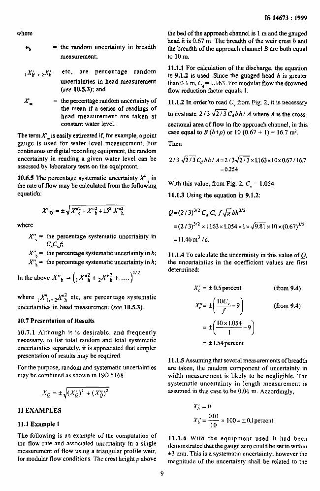
10.3.2 The standard deviation of a set of n measurements of a quantity Y under steady conditions may be estimated from the equation:
&q-y)’ ‘I2 i=l
sy = I 1 n-l
where ? is the arithmetic mean of the n measurements. The standard deviation of the mean is then given by:
and the uncertainty of the mean is twice sB (to 95
percent confidence level)‘). This uncertainty is the contribution of the observations of Y to the total uncertainty.
10.3.3 A measurement may also be subject to systematic error; the mean of very many measured values would thus still differ from the true value of the quantity being measured. An error in setting the zero of a water level gauge to invert level, for example, produces a systematic difference between the true mean measured head and the actual value. As repetition of the measurement does not eliminate systematic errors, the actual value could only be determined by an independent measurement known to be more accurate.
10.4 Errors in Coeflkient Vaiue
10.4.1 The values of the discharge coefficients C, and CV quoted in this standard are based on an appraisal of experiments, which may be presumed to have been carefully carried out, with sufficient repetition of the readings to ensure adequate precision. Random and systematic errors from this source are small. However, when measurements are made on other similar installations, systematic discrepancies between coefficients of discharge may well occur, which may be attributed to variations in the surface finish of the device, its installation, the approach conditions, the scale effect between model and site structure, etc.
10.4.2 The uncertainty in the coefficients quoted in the preceding clauses of this standard are based on a consideration of the deviation of experimental data from various sources from the equations given. The suggested uncertainties thus represent the accumulation of evidence and experience available.
“This factorofhvo assumes that n is large, for n = 6, the factor should
be 2.6; n = 8 requires 2.4; n = 10 requires 2.3; n = 15 requires 2.1,
10.5 Uncertainties in Measurements Made by the User
10.5.1 Beth random and systematic errors will occur in measurements made by the user.
10.5.2 Since neither the method of measurement nor the way in which they are to be made are specified, no numerical values can be suggested for uncertainties in this category; they shall be estimated by the user. For example, consideration of the method of measuring the weir width should permit the user to estimate the uncertainty in this quantity.
10.53 The uncertainty in the gauged head shall be determined from an assessment of the separate sources of uncertainty, for example, the uncertainty of the zero setting, wind set-up, the gauge sensitivity, backlash in the indicating equipment (where appropriate), the residual uncertainty in the mean of a series of measurements (where appropriate).
10.6 Combination of Uncertainties
10.6-l The total systematic or random uncertainty is the resultant of several contributory uncertainties, which may themselves be composite uncertainties. Provided the contributing uncertainties are independent, small and numerous, they may be combined together to give overall a random (or systematic) uncertainty at the 95 percent confidence level.
10.6.2 All sources contributing uncertainties will have both random and systematic components. However, in some cases either the random or the systematic component may be predominant and the other component can be neglected by comparison.
10.6.3 Because of the different nature of random and systematic uncertainties, they should not normally be combined with each other. However, with the provisions of 10.6.1 random uncertainties from different sources may be combined together by the root- sum of squares rule; systematic uncertainties from different sources may be similarly combined.
10.6.4 The percentage random uncertainty x9 in the rate of flow may be calculated from the following equation:
X’ -f x’2+X’2+152X’2 9- C b h
where
X’, = the percentage random uncertainty in
C,C”f; X’b = the percentage random uncertainty in b;
X’,, = the percentage random uncertainty in h.
In the above, XL = 100~ 2
and X,: = ( ,XA2 + 2X;2 +.....+Xc)“’
the random uncertainty in breadth
measurement;
etc, are percentage random
uncertainties in head measurement (see 10.5.3); and
the percentage random uncertainty of the mean if a series of readings of head measurement are taken at constant water level.
The termX”m is easily estimated if, for example, a point gauge is used for water level measurement. For continuous or digital recording equipment, the random uncertainty in reading a given water level can be assessed by laboratory tests on the equipment.
10.6.5 The percentage systematic uncertainty X”q in the rate of flow may be calculated from the followmg equatioh:
X”, = f X8$ +X$ +1.52 X$
where
X”c = the percentage systematic uncertainty in
C&J
X’\ = the percentage systematic uncertainty in b;
X”,, = the percentage systematic uncertainty in h;
( 1 X$ + J”~ +, . , . . )
112 In the above X’lh =
where lA”h,2 .l$ etc, are percentage systematic ,,
uncertainties in head measurement (see 10.53).
10.7 Presentation of Results
10.7.1 Although it is desirable, and frequently necessary, to list total random and total systematic uncertainties separately, it is appreciated that simpler presentation of results may be required.
For the purpose, random and systematic uncertainties may be combined as shown in IS0 5 168
11 EXAMPLES
11.1 Example 1
The following is an example of the computation of the flow rate and associated uncertainty in a single measurement of flow using a triangular profile weir, for modular flow conditions. The crest heightp above
IS 14673 : 1999
the bed of the approach channel is 1 m and the gauged head h is 0.67 m. The breadth of the weir crest 6 and the breadth of the approach channel B are both equal to 10 m.
11.1.1 For calculation of the discharge, the equation in 9.1.2 is used. Since the guaged head h is greater than 0.1 m, C, = 1.163. For modular flow the drowned flow reduction factor equals 1.
11.1.2 In order’to read CV from Fig. 2, it is necessary
to evaluate 2 I 3 fiC,, b h 1 A where A is the cross-
sectional area of flow in the approach channel, in this case equal to B (h+p) or 10 (0.67 + 1) = 16.7 m*.
Then
213 ~Cdbh/A=2/3&i%1.163x10x0.67116.7
= 0.254
With this value, from Fig. 2, CV = 1.054.
11.1.3 Using the equation in 9.1.2:
Q=(2 1 3)3’2 C, C, f &bh312
=(2 / 3)3’2 x 1.163 ~1.054~ 1 x m x 10 ~(0.67)“~
= 1 1.46m3 / s.
11.1.4 To calculate the uncertainty in this value of Q, the uncertainties in the coefficient values are first determined:
Xf = fO.Spercent (from 9.4)
(from 9.4)
= * 1ox1,054_9
( 1
= f 1.54 percent
11.1.5 Assuming that several measurements of breadth are taken, the random component of uncertainty in width measurement is likely to be negligible. The systematic uncertainty in length measurement is assumed in this case to be 0.0-I m. Accordingly,
xi = 0
XL- O.O’ 10
x 100 = + 0.1 percent
11.1.6 With the equipment used it had been demonstrated that the gauge zero could be set to within l 3 mm. This is a systematic uncertainty; however the magnitude of the uncertainty shall be related to the
9
IS 14673 : 1999
equipment used. There is no random uncertainty associated with the zero setting error, because, until the zero is reset the true zero will have the same magnitude and sign. Therefore,
,xj# =o
,x;zy-& x 100 = 0.45 percent
11.1.7 Uncertainties associated with different types of water level observations equipment can be determined by careM tests under controlled conditions. The random component of uncertainty can be determined by carrying out a series of readings at a given water level; however, in order to distinguish the random uncertainty from other sources of uncertainty it is necessary that these tests should be carried out with the water level always rising (or falling). For the equipment used the random component of uncertainty in water level measurement was approximately *1 mm. Systematic uncertainties in water level measurement occur due to backlash, tape stretching, etc. Where possible, corrections should be applied, but controlled tests for given types of equipment will indicate the magnitude of the residual systematic uncerta@y. In the present case this was approximately k-2.5 mm. Accordingly
*X6= 0.00 1 -x 100 = 0.15percent 0.67
,X;I=f 0.002 5 - x 100 = 0.37 percent
0.67
11.1.8 The combination of individual uncertainties to obtain the overall uncertainty in discharge may be carried out as follows:
The uncertainties in water level measurement are
assuming .Y:, is negligible:
XL= *J,xi2+ 2x;2
= f $EZ = f 0.15 percent
x;=*J_
= f ,/0.45* + 0.372 = rtr 0.58 percent
Total random uncertainty in discharge measurement:
Total systematic uncertainty in discharge
measurement:
=*(1.542 +0.12 +2.25xo.582)1’2
= f 1.77 percent.
In order to facilitate a simple presentation, the random
and systematic uncertainties may be combined by the
root-sum of squares rule
Xe = f dm = f 1.85percent
The flow rate Q may be reported as
11.46 ma/s f 1.85 percent; Random uncertainty = *0.55
percent.
11.2 Example 2
The following is an example of the computation of
the flow rate and associated uncertainty in a single
measurement of flow using a triangular profile weir,
for drowned flow conditions. The crest height p is
1 m, and the gauged height h is 2.2 m. The crest
tapping head hp is 1.7 m. The breadth of weir crest b
and the breadth of the approach channel B are both
equal to 10 m. The same digital punched type recorder
is assumed as in the previous example.
11.2.1 Since the gauged head h is greater than 0.1 m,
C,- 1.163.
11.2.2 In order to read Cyffrom Fig. 3, it is necessary
to evaluate 213 &EC,bhI A and hplh.
A = lO(2.2 + 1) = 32m2
Then
213 fiCdbhJA=2J3fixl.163x10x2.2/32
= 0.436
Also, hplh = 1.712.2 = 0.773
Then, from Fig. 3, CJ= 0.88.
11.2.3 Using the equation in 9.1.2
Q = (2 / 3)3’2 q, C,.f &bh3”
Q=(2/3)“2xl.163~0.88&%10~2.23’2
= 54.94 m3 / s = + 0.55 percent.
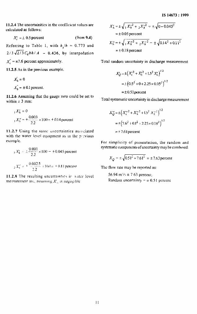
11.2.4 The uncertainities in the coefficient values are calculated as follows:
XL = Z!Z 0.5 percent
Referring to Table 1, with hPlh
2/3fiC,hhl A = 0.436, by
xi = h7.6 percent approximately.
11.2.5 As in the previous example,
x; = 0
Xi = f 0.1 percent.
11.2.6 Assuming that the gauge zero within f 3 mm:
,.q =o
(from 9.4)
= 0.773 and
interpolation
could be set to
0.003 ,,y~~+-
2.2 x100= +O.l4percent
11.2.7 Using the same cmcertaintics absul:iated with the water lcvcl equipment as III the p~vious
Total systematic uncertainty in discharge measurement
x;+p +xt2 +1.5* x;‘) I ‘2
=+(7.6’+0.1* +2:25~0.18~)“~
= * 7.6 1 percent
For simplicity of presentation, the random and systematic components of uncertainty may be combmed:
Xp = If: ,/m = f 7.63percent
The flow rate may be reported as:
54.94 ml/s f 7 63 percent;
Random uncertainty = f 0.5 1 percent.
II
IS 14673 : 1999
ANNEX A
(Clause 3)
SYMBOLS
Symbol Designation Units of
Measurement
A area of approach channel m2
B breadth of approach channel m
b breadth of weir crest m
Cd coeffkiknt of discharge non-dimensional
C” coefficient of approach velocity non-dimensional
f drowned flow reduction factor non-dimensional
g acceleration due to gravity m/s*
H total (energy) head above crest level m
h, h\ upstream gauged head above crest level m
hz downstream gauged head above crest level m
hP measured crest tapping head above crest level m
n number of measurement in a set
P height of weir (difference between mean bed level and crest level) m
8 total discharge m3/s
SY standard deviaton of a quantity Y -
SP standard deviaton of the mean
X over percentage uncertainty “A
xb percentage uncertainty in b %
XC percentage uncertainty in Cd C,f % Xh percentage uncertainty in h %
&I percentage uncertainty in the mean of a set of head measurement readings %
xQ percentage uncertainty in Q %
b random uncertainty in breadth measurement m
Superscripts to X : ’ denotes random components of uncertainty ” denotes systematic components of uncertainty
12
.
Bureau of Indian Standards
BIS is a statutory institution established under the Bureau of Indian Standards Act, 1986 to promote harmonious development of the activities of standardization, marking and quality certification of goods and attending to connected matters in the country.
Copyright
BIS has the copyright of all its publications. No part of these publications may be reproduced in any form without the prior permission in writing of BIS. This does not preclude the free use, in the course of implementing the standard, of necessary details, such as symbols and sizes, type or grade designations. Enquiries relating to copyright be addressed to the Director (Publications), BIS.
Review of Indian Standards
Amendments are issued to standards as the need arises on the basis of comments. Standards are also reviewed periodically; a standard along with amendments is reaffirmed when such review indicates that no changes are needed; if the review indicates that changes are needed, it is taken up for revision. Users of Indian Standards should ascertain that they are in possession of the latest amendments or edition by referring to the latest issue of ‘BIS Handbook’ and ‘Standards: Monthly Additions’.
This Indian Standard has been developed from Dot : No. RVD 1 (184).
Amendments Issued Since Publication
Amend No. Date of Issue Text Affected
BUREAU OF INDIAN STANDARDS
Headquarters:
Manak Bhavan, 9 Bahadur Shah Zafar Marg, New Delhi I IO 002 Telephones : 323 01 3 1, 323 33 75, 323 94 02
Telegrams : Manaksanstha (Common to all offices)
Regional Offices : Telephone
Central : Manak Bhavan, 9 Bahadur Shah Zafar Marg 323 76 17 NEW DELHI 110 002 323 38 41
Eastern : l/14 C. IT. Scheme VII M, V. I. P. Road, Kankurgachi 337 84 99,337 85 61 CALCUTTA 700 054 337 86 26,337 91 20