Disclosure to Promote the Right To Information Whereas the Parliament of India has set out to provide a practical regime of right to information for citizens to secure access to information under the control of public authorities, in order to promote transparency and accountability in the working of every public authority, and whereas the attached publication of the Bureau of Indian Standards is of particular interest to the public, particularly disadvantaged communities and those engaged in the pursuit of education and knowledge, the attached public safety standard is made available to promote the timely dissemination of this information in an accurate manner to the public. इंटरनेट मानक “!ान $ एक न’ भारत का +नम-ण” Satyanarayan Gangaram Pitroda “Invent a New India Using Knowledge” “प0रा1 को छोड न’ 5 तरफ” Jawaharlal Nehru “Step Out From the Old to the New” “जान1 का अ+धकार, जी1 का अ+धकार” Mazdoor Kisan Shakti Sangathan “The Right to Information, The Right to Live” “!ान एक ऐसा खजाना > जो कभी च0राया नहB जा सकता ह ै” Bhartṛhari—Nītiśatakam “Knowledge is such a treasure which cannot be stolen” IS 14870 (2000): Transformers and Inductors for Use in Electronic and Telecommunication Equipment - Measuring Methods and Test Procedures [LITD 5: Semiconductor and Other Electronic Components and Devices]
Transcript
Disclosure to Promote the Right To Information
Whereas the Parliament of India has set out to provide a practical regime of right to information for citizens to secure access to information under the control of public authorities, in order to promote transparency and accountability in the working of every public authority, and whereas the attached publication of the Bureau of Indian Standards is of particular interest to the public, particularly disadvantaged communities and those engaged in the pursuit of education and knowledge, the attached public safety standard is made available to promote the timely dissemination of this information in an accurate manner to the public.
इंटरनेट मानक
“!ान $ एक न' भारत का +नम-ण”Satyanarayan Gangaram Pitroda
“Invent a New India Using Knowledge”
“प0रा1 को छोड न' 5 तरफ”Jawaharlal Nehru
“Step Out From the Old to the New”
“जान1 का अ+धकार, जी1 का अ+धकार”Mazdoor Kisan Shakti Sangathan
“The Right to Information, The Right to Live”
“!ान एक ऐसा खजाना > जो कभी च0राया नहB जा सकता है”Bhartṛhari—Nītiśatakam
“Knowledge is such a treasure which cannot be stolen”
“Invent a New India Using Knowledge”
है”ह”ह
IS 14870 (2000): Transformers and Inductors for Use inElectronic and Telecommunication Equipment - MeasuringMethods and Test Procedures [LITD 5: Semiconductor andOther Electronic Components and Devices]
IS 14870:2000
IEC 1007 (1994)
w?a7J7i’7’@
—
Indian Standard
TRANSFORMERS AND INDUCTORS FOR USEIN ELECTRONIC AND TELECOMMUNICATION
EQUIPMENT— MEASURING METHODSAND TEST PROCEDURES
Ochber 2000
ICS 29.180:29.100.10
0 BIS 2000
BUREAU OF INDIAN STANDARDSMANAK BHAVAN, 9 BAHADUR SHAH ZAFAR MARG
NEW DELHI 110002
Price Group 15
IS 14870 : 2000
Magnetic Components and Ferrite Materials Sectional Committee, LTD 13
NATIONAL FOREWORD
This Indian Standard which is identical with IEC 1007(1994) ‘Transformers and inductors for use inelectronic and telecommunication equipment — Measuring methods and test procedures’ issued byInternational Electrotechnical Commission (lEC) was adopted by the Bureau of Indian Standards on therecommendation of the Magnetic Components and Ferrite Materials Sectional Committee and approvalof the Electronics and Telecommunication Division Council.
The text of the IEC has been approved as suitable for publication as Indian Standard without deviations.Certain conventions are however, not identical to those used in Indian Standards. Attention is particu-larly drawn to the following:
a) Wherever the words ‘International Standard’ appear referring to this standard, they shouldbe read as ‘Indian Standard’.
b) Comma [,) has been used as a decimal marker while in Indian Standards, the current practiceis to use a point (.) as the decimal marker.
CROSS REFERENCES
In the adopted standard, reference appears to certain International Standards for which IndianStandards also exist. The corresponding Indian Standards which are to be substituted in their placeare listed below along with their degree of equivalence for the editions indicated:
International Standard Corresponding Indian Standard Degree ofEquivalence
IEC 27: Letter symbols to be 1S 3722:1983 Letter symbols and signs Technicallyused in electrical technology Used in electrical technology Equivalent
IEC’50 International IS 1885 Electrotechnical vocabulary doElectrotechnical Vocabulary
IEC 68-1 (1988) Environmental a) IS 9000 (Part 1):1988 Basic environ- dotesting — Part 1 : General and mental testing procedures for elec-guidance tronic and electrical items: Part 1Amendment 1 (1992) General
b) IS 9001 (Part 1) :1984 Guidance forenvironmental testing: Part 1 General
IEC 68-2-1 (1990) Environmental IS 9000 (Part 2),: 1977 Basic environmen-testing — Part 2: Tests — tal testing procedures for electronic andTests A: Cold electrical items: Part 2 Cold testAmendment 1(1 993)
IEC 68-2-2 (1974) Environmental IS 9000 (Part 3) :1988 Basic environmen-testing — Part 2: Tests — tal testing procedures for electronic andTest B: Dry heat electrical items: Part 3 Dry heat testAmendment 1(1 993)
IEC 68-2-3 (1969) Environmental IS 9000 (Part 4) :1988 Basic environmen-testing — Part 2: Tests — tal testing procedures for electronic andTest Ca: Damp heat, steady state electrical items: Part 4 Damp heat (steady
IEC 68-2-20 (1979) Environmen-tal testing — Part 2: Tests —Test T SolderingAmendment 2 (1989)
IEC 68-2-21 (1983) Environmen-tal testing — Part 2: Tests —Test U: Robustness of terminationsand integral mounting devicesAmendment 2 (1991)Amendment 3 (1992)
IEC 68-2-27 (1987) Environmen-tal testing — Part 2: Tests —Test Ea and guidance: Shock
IEC 68-2-29 (1987) Environmen-tal testing — Part 2: Tests —Test Eb and guidance: Bump
a)
b)
a)
b)
IS 9000 (Part 8):1988 Basicenvironmental testing procedures forelectronic and electrical items: Part 8Vibration (sinusoidal) test
IS 9001 (Part 13) :1979 Guidance forenvironmental testing : Part 13 Vibra-tion (sinusoidal) test
IS 9000 (Part 9) :1981 Basicenvironmental testing procedures forelectronic and electrical items: Part 9Acceleration (steady state) test
IS 9001 (Part 15) :1984 Guidance forenvironmental testing: Part 15 Accel-eration (steady state) test
IS 9000 (Part 10) :1979 Basic environmen-tal testing procedures for electronic andelectrical items: Part 10 Mould growth test
IS 9000 (Part 13) :1981 Basic environ-mental testing procedures for electronicand electrical items: Part 13 Low air pres-sure test
IS 9000 (Part 14) :1981 Basic environ-mental testing procedures for electronicand electrical items: Part 14 Test N:Change of temperature
1S 9000 (Part 15) :1982 Basic environ-mental testing procedures for electronicand electrical items: Part 15 Sealing test
IS 9000 (Part 18) :1981 Basic-environmen-tal testing procedures for electronic andelectrical items : Part 18 Solderabililty test
IS 9000 (Part 19) :1981 Basic environ-mental testing procedures for electronicand electrical items: Part 19 Robustnessof terminations and integral mountingdevices
a)
b)
a)
b)
IS 9000 (Part 7/See 1) :1979 Basicenvironmental testing procedures forelectronic and electrical items: Part 7Impact test, Section 1 Shock
IS 9001 (Part 17/Sec 1) :1985 Guid-ance for environmental testing: Part17 Impact test, Section 1 Shock test
IS 9000 (Part 7/See 2) :1979 Basicenvironmental testing procedures forelectronic and electrical items: Part 7Impact test, Section 2 Bump
IS 9001 (Part 17/Sec 2) :1985 Guid-ance for environmental testing: Part17 Impact test, Section 2 Bump test
2
TechnicallyEquivalent
do
do
do
do
do
do
do
do
do
do
do
do
do
—
IS 14870 : 2000
IEC 68-2-30 (1980) Environmen-tal testing — Part 2: Tests —Test Db and guidance : Dampheat, cyclic (12+12 - hour cycle)Amendment’1 (1985)
IEC 68-2-42 (1982) Environmen-tal testing — Part 2: Tests — TestKc: Sulphur dioxide test for con-tacts and connections
IEC 68-2-45 (1980) Environmen-tal testing — Part 2: Tests — TestXA and guidance: Immersion incleaning solvents
IEC 68-2-52 (1984) Environmen-tal testing — Part 2: Tests — TestKb: Salt mist, cyclic (sodiumchloride solution)
IEC 270 (1981) Partial dischargemeasurements
IEC 367-1 (1982) Cores for induc-tors and transformers fortelecom-munications— Part 1 : Measur-ing methodsAmendment 1 (1984)Amendment 2 (1992)
IEC 551(1 987) Determination oftransformer and reactor soundlevels
ISO 3:1973 Preferred numbers—Series of preferred numbers
1S0 497:1973 Guide to the choice.of series of preferred numbersand of series containing morerounded values of preferrednumbers
ISO 1000:1992 S1 units andrecommendations for the use oftheir multiples and of certain otherunits
IS 9000 (Part 5/ Sec 2) :1981 Basic envi-ronmental testing procedures for electronicand electrical items: Part 5 Damp heat(cyclic) test, Sec 2 12+1 2 h cycle
IS 9000 (Part 26):1 980 Basic environmen-tal testing procedures for electronic andelectrical items: Part 26 Sulphur dioxidetest for contacts and connections
a)
b)
IS 9000 (Part 20) :1979 Basic envi-ronmental testing procedures for elec-tronic and electrical items : Part 20Resistance to cleani;g solvents andpermanence of marking
IS 9001 (Part 5) :1979 Guidance forenvironmental testing.: Part 5Resistance to cleaning solvents andpermanence of marking
9000 (Part 11) :1983 Basic environ-1smental testing procedures for electronicand electrical items: Part 11 Salt mist test
IS 6209:1982 Methods for partial dis-charge measurement
IS 7687:1980 Methods of measurementfor cores for inductors and transformersfor telecommunications
IS 13964:1994 Methods of measurementof transformer and reactor sound levels
IS 12032:1987 Graphical symbols fordiagrams in the field of electrotechnology
IS 9779:1981 Sound level meters
IS 1076 (Part 1) :1985 Preferred numbers:Part 1 Series of preferred numbers
IS 1076 (Part 3) :1985 Preferred numbers: Part 3 Guide to the choice of series ofpreferred numbers and of series contain-ing more rounded values of preferrednumbers
IS 10005:1994 S1 units and recommen-dations for use of their multiples and ofcertain other units
TechnicallyEquivalent
do
do_—
do
do
do
do
do
Identical
TechnicallyEquivalent
Identical
do
do
3
IS 14870 : 2000
The concerned Technical Committee responsible for preparation of this standard has reviewed theprovisions of the following International Publications and has decided that they are acceptable for use inconjunction with this standard:
IEC 68-2-58(1 989) Environmental testing—Part 2: Tests—Test Td: Solderability, resistance todissolution of metallization and to soldering heat of surface mounting devices (SMD)
IEC 695-2-2(1991) Fire hazard testing — Part 2: Test methods — Section 2: Needle-flame test
IEC 695-2-4/0(1 991) Fire hazard testing — Part 2: Test methods — Section 4/Sheet O: Diffusion typeand pre-mixed type flame test methods
IEC 695-2-4/1(1 991) Fire hazard testing — Part 2: Test methods — Section 4/Sheet 1:1 kW nominalpre-mixed test flame and guidance
Only the English language text of the International Standard has been retained while adopting it in thisIndian Standard.
4
IS 14870:2000IEC 1007 (1994)
Indian Standard
TRANSFORMERS AND INDUCTORS FOR USEIN ELECTRONIC AND TELECOMMUNICATION
EQUIPMENT— MEASURING METHODSAND TEST PROCEDURES
I Scope
This standard describes measuring methods and test procedures for inductors and trans-formers for use in electronic and telecommunication equipment that may be involved in
any specifications for such components, in particular those forming part of the IEC QualityAssessment System for Electronic Components (IECQ scheme).
2 Normative references
The following normative documents contain provisions which, through reference in thistext, constitute provisions of IEC 1007. At the time of publication, the editions indicatedwere valid. All normative documents are subjetA to revision, and parties to agreementsbased on IEC 1007 are encouraged to investigate the possibility of applying the mostrecent editions of the normative documents indicated below. Members of IEC and ISOmaintain registers of currently valid International Standards.
IEC 27: Letter symbols to bi used in electrical technology
IEC 44-4:1980, Instrument transformers – Part 4: Measurement of partial discharges
IEC 50, International Electrotechnical Vocabulary (IEV)
IEC 68-1: 1988, Environmental testing – Part 1: General and guidanceAmendment 1 (1992)
IEC 68-2-6: 1982, Environmental testing - Part 2: Tests – Test Fc and guidance: Vibration(sinusoidal)
5
Is 14870:2000IEC 1007 (1994)
IEC 68-2-7: 1983, Environmental testing - Part 2: Tests - Test Ga and guidance: Accel-eration, steady stateAmendment 1 (1986)
IEC 68-2-10: 1988, Environmental testing - Part 2: Tests - Test J and guidance: Mou/dgrowth
IEC 60-2-13:1983, Environmental testing - Part 2: Tests - Test M: Low air pressure
IEC 68-2-14:1984, Environmental testing – Part 2: Tests - Test N: Change of temperatureAmendment 1 (1986)
IEC 68-2-17:1978, Environmental testing - Part 2: Tests - Test Q: SealingAmendment 4 (1991)
IEC 68-2-20:1979, Environmental testing - Part 2: Tests – Test T: SolderingAmendment 2 (1989)
IEC 68-2-21:1983, Environmental testing - Part 2: Tests - Test U: Robustness of termin-
ations and integral mounting devicesAmendment 2 (1991), Amendment 3 (1992)
lEC 68-2-27:1987, Environmental testing - Part 2: Tests - Test Ea and guidance: Shock
IEC 68-2-29:1987, Erwironmenta/ testing - Part 2: Tests - Test Eb and guidance: Bump
IEC 68-2-30:1980, Environmental testing - Part 2: Tests - Test Db and guidance: Dampheat, cyclic (12 + 12-hour cycle)Amendment 1 (1985)
IEC 68-2-42: 1982, Environmental testing – Pati 2: Tests - Test Kc: Sulphur dioxide testfor contacts and connections
IEC 68-2-45:1980, Environments/ testing - Part 2.’ Tests - Test XA and guidance: immer-
sion in cleaning solvents
IEC 68-2-52: 1984, Environmental testing - Part 2: Tests - Test Kb: Salt mist, cyclic
(sodium chloride solution)
IEC 68-2-58: 1989, Environmental testing - Part 2: Tests - Test Td: .Solderability,resistance to dissolution of metallization and to soldering heat of Surface MountingDevices (SMD)
IEC 270:1981, Partial discharge measurements
6
IS 14870:2000IEC 1007(1994)
IEC 3-67-1: 1982, Cores for inductors and transformers for telecommunications - Part 1:Measuring methodsAmendment 1 (1984), Amendment 2 (1992)
IEC 551:1987, Determination of transformer and reactor sound levels
IEC 695-2: Fire hazard testing - Part 2: Test methods
IEC 69?5-2-2: 1991, Fire hazard testing - Part 2: Test methods - Section 2: Needle-flametest
IEC 695-2-4/0: 1991, Fire hazard testing - Part 2: Test methods – Section 4/Sheet O:
Diffusion type and pre-mixed type flame test methods
IEC 695-2-4/1: 1991, Fire hazard testing - Part 2: Test methods - Section 4/Sheet 1:1 kW nominal pre-mixed test flame and guidance
ISO 3:1973, Preferred numbers - Series of preferred numbers
ISO 497: 1973, Guide to the choice of series of preferred numbers and of series contain-ing more rounded values of preferred numbers
ISO 1000:1992, S1 units and recommendations for the use of their multiples and of certain
other units
3 Terminology
For the purpose of this standard the following definitions apply in addition to those ofIEC 50:
3.1 component: A transformer or an inductor.
3.2 peak working v“oltage: The maximum instantaneous voltage for which the windinginsulation is rated under working circuit conditions.
3.3 pulse waveform parameters (see figure 1)
a) peak pulse amplitude, L/m: Th’e maximum value of an extrapolated smooth curvethrough the top of the pulse, excluding any initial “spike” or “overshoot”, the duration ofwhich is less than 10 0/0of the pulse duration.
b) pulse duration, td: The time interval between the first and last instants at which thepulse amplitude equals 50 ‘/. of the peak pulse amplitude.
7
% u. t
100
90
80
50
10
0
-lo
Leading edge
1Overshoot Pulse crest
[)
I /
---
, I .I
-—. - .-/4----.—-----------—-1
Pulse duration
- t(j
Risetime
*tr-o
Trailing adge
.LDroop
A--
4\ Return backswing
Cycle tima
Falltime
/ \
I\
Recovery timeI * *
NOTE - For clarity in illustrating droop, the 80V0 and 10% points have been used in constructing the linewhich determines the border between the puke 106 and the trailing edge.
Figure 1 - Pulse waveform parameters
I
IS 14870:2000IEC 1007(1994)
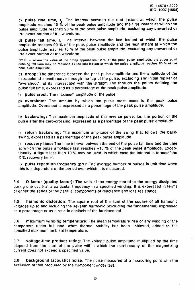
c) pulse rise time, tr: The interval between the first instant at which the pulseamplitude reaches 10 0/0of the peak pulse amplitude and the first instant at which thepulse amplitude reaches 90 O/.of the peak pulse amplitude, excluding any unwanted orirrelevant portion of the waveform.
d) pulse fall time, $: The interval between the last instant at which the Pulseamplitude reaches 90 % of the peak pulse amplitude and the next instant at which thepulse amplitude reaches 10 O/. of the peak pulse amplitude, excluding any unwanted orirrelevant portion of the waveform.
NOTE - Where the value of the droop approaches 10 % of the peak pulse amplitude, the upper pointdefining fall time may be replaced by the last instant at which the pulse amplitude reaches 80 % of thepeak pulse amplitude.
e) droop: The difference between the peak pulse amplitude and the amplitude of theextrapolated smooth curve through the top of the pulse, excluding any initial “spike” or‘overshoot”, at its intersection with the straight line through the points defining thepulse fall time, expressed as a percentage of the peak pulse amplitude.
f) pulse c-rest: The maximum amplitude of the pulse.
g) overshoot: The amo,klnt by which the pulse crest exceeds the peak pub
amplitude. Overshoot is expressed as a percentage of the peak pulse amplitude.
h) backswing: The maximum amplitude of the reverse pulse, i.e. the poflion of thepulse after the zero-crossing, expressed as a percentage of the peak pulse amplitude.
i) return backswing: The maximum amplitude of the swing that follows the back-swing, expressed as a percentage of the peak pulse amplitude.
j) recovery time: The time interval between the end of the pulse fall time and the time
at which the pulse amplittide last reaches +1 O % of the peak pulse amplitude. Excep-tionally, a figure less than 10 O/. may be used, in which case the interval is termed “theX 0/0recovery time”.
k) pulse repetition frequency (prf): The average number of pulses in unit time whenthis is independent of the period over which it is measured.
3.4 Q factor (quality factor): The ratio of the energy stored to the energy dissipatedduring one cycle at a particular frequency in a specified winding. It is expressed in termsof either the series or the parallel components of reactance and loss resistance.
3.5 harmonic distortion: The square root of the sum of the square of all harmonicvoltages up to and including the seventh harmonic (excluding the fundamental) expressed
as a percentage or as a ratio in decibels of the fundamental.
I\ 3.6 maximum winding temperature: The mean temperature rise of any winding of the
component under full load, when thermal stability has been achieved, added to thespecified maximum ambient .temperature.
3.7 voltage-time product -rating: The voltage pulse amplitude multiplied by the time
elapsed from the start of the pulse within which the non-linearity of the magnetizing
I current does not exceed a specified value.
——
3.8 background (acoustic) noise: The noise measured at a measuring point with theexclusion of that produoed by the component under test.
9
IS 14870:2000IEC 1007(1994)
3.9 compass safe distance: The distance from the pivot of the test magnetometer orcompass to the nearest point on the surface of the component under test, at which themagnetic deviation is limited to a stated value.
3.10 duty ratio; duty factor,: The ratio of pulse duration td to the cycle time.
3.11 current transformer parameters
a) burden: That property of the circuit connected to the secondary winding of acurrent transformer which determines the real and reactive power at the secondaryterminals. It is expressed as total impedance with effective resistive and reactivecomponents or as the total volt-amperes and power factor at the specified values ofcurrent and frequency.
b) current transformation ratio, k: The ratio of the r.m.s.. vaiue of the primary currentto the r.m. s. value of the secondary current under specified conditions.
c) phase angle: The angular displacement between the vectors representing the
primary and secondary currents of the transformer. The phase angle is positive whenthe secondary current leads the primary current, ,
d) ratio error: The difference between the measured current transformation ratio kand its nominal value kn, divided by the measured value, and expressed as a percent-age.
kn-kratio error = — x 100 (per cent)
k
3.12 electrostatic screen: A conducting screen inserted between windingsis connected to earth, considerably reduces the transference of unwantedone winding to the other via interwinding capacitance.
that, when itsignals from
3.13 safety screen: A conducting screen inserted between windings that, when it isconnected to earth, effectively prevents fault currents flowing between those windings, inthe event of an insulation failure.
3.14 polarity (applicable to single-phase windings): A property of a single-phasewinding such that a terminal on one winding has the same polarity as a terminal onanother winding if, when the other ends of the windings are connected to form a common
terminal and the transformer/inductor is energized with a sinusoidal voltage, the inducedvoltage appearing between each of the two terminals and
positively through zero at the same instant of time.
3.15 uniformly-insulated winding: ,A winding in whichall points, designed to withstand an electric strength testinsulation of the high-voltage end.
the common t~rminal is rising
the insulation to earth is, atof a value appropriate to the
3.16 graded-insulated winding: A winding in which insulation to earth is graded fromthe amount at the high-voltage end to a smaller amount at the low-voltage end.
NOTE - Such a winding should withstand an electric strength test ot a value appropriate to the insulation ofthe low-voltage end
10
IS 14870:2000IEC 1007(1994)
4 Test procedures
4.1 Test and measurement conditions
Unless otherwise specified all tests shall be carried out under standard atmosphericconditions for testing as specified in IEC 68-1. Where there is a requirement for compo-nents to attain temperature stability this shall be in accordance with 4.8 of IEC 68-1.
Unless otherwise stated in the detail -specification, all voltages and currents shall besinusoidal; values shall be taken as r.m. s. and polyphase supplies shall be assumed to bebalanced.
The “information to be stated” that is required to complete the descriptions of test methods
in this clause shall be specified in the relevant detail specification for the component. Thedetail specification shall also specify the test fixture to be used in association with acomponent, where this is intended for use at frequencies high enough for the length of testleads to become significant.
4.1.1 Measurement uncertainty
The limits quoted in detail specifications shall be absolute. The tolerance values applying
to the actual measurement system shall be taken into account when the measurementsare assessed against specification limits. Where tolerances in respect of set conditions orinstrument error have been prescribed these shall be regarded as additional minimumrequirements.
4.1.2 Alternative test methods”
The test and measurement methods given in the relevant specification shall not beregarded as the only methods to be used. Special test equipment and automatic test sets
are available, which may also be used. However, the tester shall satisfy the customer orrelevant authority (see Note 1) that any alternative methods which he may use will giveresults equivalent (see Note 2) to those obtained by standard methods, In the case ofdispute, for referee and reference purposes the specified methods only shall be used.Alternative test methods” shall not be shown in detail specifications.
NOTES
1 Such as a National Supervising Inspectorate within the IECQ scheme
2 By “equivalent- It is meant that the value of the characteristic established by such other method anddeemed acceptable in accordance with the limits ascribed to such other method will fall within the specifiedlimits when measured by the specified method.
4.2 Visual inspection.
Visual inspection shall be performed un-der normal factory lighting without visual aids. The
, condition, workmanship, marking and finish shall be satisfactory.
NOTE - If special lighting and/or visual aids are necessary for the acceptance of particular components.(e.g. very small components), these may be specified as additional tests in the relevant detail specification.
11
—
IS 14870:2000IEC 1007 (1994)
4.2.1 Safety screen position
NOTE - Sometimes the term “isolating screen” is used as an alternative to ‘safety screen..
Purpose: To determine the position of a safety screen in relation to adjacent windings.
Procedure: The fitted and positioned safety screen shall be inspected before being
obscured by subsequent windings. The safety screen shall:
a) totally cover the winding around which it is wrapped such that the “finish” end over-laps the “start” end by no less than the amount specified in the detail specification;
b) be adequately insulated so as not to comprise a short-circuited winding;
c) have edges extending sufficiently along ,the winding being screened to preventdirect contact between windings.
NOTE - Screens fitted to toroidal transformers may consist of a number of turns of conductive stripprovided that each turn overfaps the -adjacent turn by not fess than 5 % of the strip width.
Information to be stated:
- minimum overlap.
4.2.2 Quality of solder joints
NOTE - A good solder joint is one that has excelfent efectricaf contact between the parts joined and good
mechanical strength. Exampfes of good solder joints are shown in figure 2. Figure 3 illustrates defectivejoints.
Purpose: To determine the quality of all solder joints.
Procedure: All solder joints shall be inspected to ensure that the following requirements
are complied with:
Requirements: Soldered joints shall:
a) exhibit good tinning as evidenced by the free flowing of solder with wetting of thetermination;
b) be smooth with no spikes;
c) be bright and shiny;
d) be without rough patches;
e) shall have a concave surface and the outline of” the wire shall be visible under thesurface of the solder;
f) not have been moved during soldering (such joints exhibit an “orange peel” effect,as shown in figure 3a);
. g) not be “dry” (that is, shall not exhibit a distinct line where the solder fillet joins the
wire or have a high contact angle between the solder and the wire (see figure 3b));
h) be wired at terminals in such a way as to leave no residual stress (s-ee figure 3c);
i) not exhibit “wicking” (that is, the joining wire shall not be overheated, leading to the
movement of solder into multi-stranded wires (see figure 3d)).
12
$
IS 14870:2000IEC 1007(1994)
A/---Figure 2- Examples of good solder joints
Figure 3a - Moved joint
Figure 3C - Mechanically stressed joint
Figure 3b. Dry joints
III ! Insulation
I
Ii
II
Solderinthe multistrand wire
~[ \(/makesi’brin’e
Figure 3d - Wicking
. ..—
Figure 3- Examples of defective joints
13
IS 14870:2000IEC 1007(1 994)
4.3 Dimensioning and gauging procedure
The dimensions shall be verified as being in accordance with the relevant specification.
4.4 Electrical test procedures
4.4.1 Winding resistance
4.4.1.1 D. C. winding resistance
Purpose: To determine the d.c. resistance of a winding or windingsterminations.
Procedure: The resistance shall be measured by a suitable method.
Where required by the detail specification, the ambient temperature
between specified
e (in “C) shall bemeasured and the result of the resistance measurement ‘R~ (in Q) corrected to the
corresponding value at 20 “C, R20 (in Q) by means of the following formula:
k+20R20 = R.
k+fl
where. k is a constant related to the thermal coefficient of resistivity. For the purposes of
this standard, the value for copper shall be taken as 234,5 and for aluminium as 228,1.
NOTE - For safety reasons, consideration should be given to short-circuiting windings capable of produc-ing high voltages at current interruption,
Information to be stated:
a) terminations between which the measurement is to be made;
b) whether the result of measurement should be corrected to 20 “C, and if so, thevalue of k to be used for materials other than copper or aluminium.
NOTES
1 The selected method should be determined by the ease of operating the lest and the accuracy re-
quired. The accuracy of the equipment should be at least ten times better than the “accuracy required of the
test.
2 The measuring current should not be so large as to cause self-heating or to have a significant magnet-
izing effect on the component.
4.4.1.2 Continuity
Pwpose: To verify the continuity of a specified winding.
Procedure: Continuity shall be established using a suitable d.c. or a.c. voltage or current
source, and a suitable detector.
Information to be stated:
– winding to be tested.
. ......
14
IS 14870:2000IEC 1007(1994)
NOTES
1 The current should not be so large as to have a significant magnetizing effect on the component.
2 Care should be taken in testing a winding with a high inductance value as a high voltage may begenerated.
3 Where there are parallel paths, as with multiple windings or in polyphase components, a d.c.resistance check may be necessary to ensure that the path under examination is not being influenced by
shunt paths.
4.4.2 /nsu/ation tests
4.4.2.1 E/ectric strength test
Purpose: To ensure that the insulation of uniformly-insulated windings and the low-voltage end insulation of graded-insulated windings are adequate.
NOTES
1 This test is not suitable for the high-voltage end insulation of windings having graded insulation or
designed to have one point earthed”. The high-voltage end insulation of such windings can be tested only
by the application of an appropriate induced voltage test (see item b) of speciaf conditions of test of4.4.2.2).
2 in certain cases it may be appropriate to demonstrate the adequacy of thp low-voltage end insulationof graded-insulated windings during the induced voltage test (see item b) of specisl conditions of test of4.4.2.2).
Procedure: A test voltage whose value is selected from the table below, unless otherwisespecified, shall be applied between specified pairs of isolated elements of the component.All windings shall be short-circuited. Windings and screens on one side of. the insulationsystem shall be connected to frame, core and earth while windings and screens on theother side shall be connected together.
Electric strength test voltages
I Peak working voltage
I vpk
<25
>25 to 50>50 to 100>100 to 175>175 to 700>700
AC. test voltage, 45-65 Hz
(r.m,s. ) D.C. test volta~e
v vr,m. s.
50
1003005002,8 x peak working voltage1,4 x peak working voltage
+1000
71
1414247074 x peak working voltage2 x peak working voltage
+ 1-400
The test voltage shall be increased at a convenient rate but not exceeding 2 kV per sec-ond, from zero to the specified value, maintained at this value for the specified time (un-less breakdown occurs), then decreased to zero at the same rate.
. In the USA, ‘ground” is used in place of “earth- and “grounded” in place of ‘earthed”.
15
—
IS 14870:2000IEC 1007(1994)
For fluid-filled components, except for those designed for operation in one plane only andso marked, approximately half the test sample shall be tested with terminals uppermostand half with the terminals underneath.
If a specified environ,mntal conditioning is required for this test the component shall beheld for a minimum of 6 h unless otherwise specified in the specified conditions. (SeeIEC 68 for information on environmental testing.)
There shall @ - ~ jvidence of heating, breakdown or deterioration. Ionization shall not beregarded as a critcci:,n of breakdown. 7ne leakage current shall not exceed the specifiedvalue.
Information to be stated: +
a) terminations between which the test is to be made;
b) test voltage (for a winding having graded-insulation, values shall be given for bothends of the winding);
c) frequency of a.c. test voltage (if different from the values shown in the table);
d) test duration;
e) maximum leakage current, if specified.
NOTES
3 If breakdown occurs during the test it can at first be detected by sporadic and intermittent increases inleakage current followed by a significant increase io a constant higher value which, on many electricstrength test sets, is accompanied by a partial or complete collapse of the voltage. This type of breakdownmay be caused by partial breakdown in ionized voids and weakened insulation which then avalanches to
complete breakdown in the form of arc-over or arc-through.
4 Electric strength test voltages may be hazardous Extrame care should be taken in performing thistest.
4.4.2.2 Induced voltage test
Purpose: To verify the adequacy of inter-turn and inter-layer insulation of transformers
and inductors, and to verify the adequacy of the high-voltage end insulation of windingshaving graded-insulation.
Special conditions of test
The following special conditions apply:
a) Uniformly insulated windings are normally tested as in Procedure 1, 2 or 3, asappropriate. Any point of a winding may be earthed during the test as specified.
16
b) Windings having graded-insulation are normally tested a~ in Procedure 1, 2 .or 3,
as appropriate. A poir?t on such a winding may be earthed or raised to a specified volt-age above earth during the test. The induced voltage shall be such that, when addedvectorially to any applied voltage, the high-voltage end of the winding is raised to the -appropriate peak test voltage given in 4.4.2.1, Procedure.
IS 14870:2000IEC 1007 (1994)
If the specified voltage above earth is alternating, then it shall be of the same fre-quency as the induced voltage.
NOTE 1 - In general, during the execution of the induced voltage test, no winding should be permitted to‘float-, i.e. to remain unconnected at both ends.
Procedure 1: Applicable to transformers and inductors intended for energizing bysinusoidal waveforms.
A specified test voltage of not less than twice the rated supply voltage at a frequency ofnot less than twice the lowest rated frequency shall be applied across the specifiedwinding. The duration and manner of application shall be as specified in the detail specifi-cation.
Procedure 2: Applicable to transformers and inductors intended for energizing by pUISewaveforms.
Specified test voltage pulses of amplitude not less than twice the rated pulse amplitude, ata specified -pulse repetition frequency of not less than 25 YOof the maximum rated pulserepetition frequency and with a specified pulse duration not less than 25 % of the ratedmaximum pulse duration and normally* not greater than 50 ‘A of the rated pulse durationshall be applied across the winding. The duration and manner of application shall be asspecified in the detail specification.
Procedure 3: Applicable to transformers and inductors intended for energizing bynon-sinusoidal periodic waveforms such as those in power supplies operating with semi-
conductors in a switched mode.
A specified sinusoidal test voltage of peak value not less than twice the maximum ratedpeak value for the input voltage waveform and at a specified frequency, derived asfollows, shall be applied across the specified winding. The duration and manner of appli-
cation shall be as specified in the detail specification.
The test frequency shall be such that its cyclic period is normally** not greater than the
effective shortest half-cycle period of the operative waveform for which the component isintended e.g. in the case of pulse width modulated symmetrical or asymmetricalwaveforms the effective half-cycle shall be taken to be the effective minimum on-time of
~he electronic switch.
Duration for application of test voltage in ‘Procedures 1, 2 and 3
The duration of application of the test voltage shall be specified as one of the following:
a) The applied voltage shail be raised from one-third of the specified voltage to the full
. .
Pulse durations greater than 50 “A of the rated maximum value may be specified provided that core fluxsaturation or other abnormalities are shown not to be incurred thereby.
A lower test frequency may be specified provided that core flux saturation or other abnormalities are shownnot to be incurred thereby
17
IS 14870:2000IEC 1007(1994)
value which shall then be maintained for 60 s f 5 s before reducing the voltage to one-third of its value and hence to-zero.
b) 5 s to 10 s (value to be stated).
Requirements:
There shall be no evidence of heating, breakdown or deterioration. Ionization shall not beregarded as a criterion of breakdown.
Information to be stated in the detail specification:
a) the test voltage (r. m.s. or peak as applicable);
b) ‘the winding(s) to be energized (see note 2);
c) the winding point intended to be connected to a known potential and the value ofthis potential (if applicable);
d) the duration of application of test voltage;
e) the test frequency or pulse repetition frequency (as applicable);
f) the pulse duration (applicable to Procedure 2).
NOTE 2- A source of test voltage may be connected to windings other than the normal input winding in
order to obtain the necessary voltages,
4.4.2.3 Insulation resistance
Purpose: To measure the resistance of the insulation between the various parts of thecomponent.
Procedure: Unless otherwise specified the insulation resistance shall be -measured with a
d.c. voltage of either:
100 V t 15 V for windings with peak working voltage c 500 V, or
500 V + 50 V for windings with peak working voltage 2500 V.
The test voltage shall be applied until a steady reading is obtained or, failing that, for 60 s*5S.
If a specified environmental conditioning is required the component shall be held in thespecified condition for a minimum of 6 h, unless otherwise specified. (See IEC 68 for infor-mation on environmental testing.)
Information to be stated:
a) terminations between which the measurement is to be made;
b) peak working voltage of each winding;
c) environmental conditioning.
18
IS 14870:2000IEC 1007(1 994)
4.4.3 Losses
4.4.3.1 No-load current
Purpose: To verify that the core is of the required quality and is correctly assembled and
that there are no short-circuited parts of the windings.
Procedure: The specified voltage at the frequency or frequencies spdcified shall beapplied from a low impedance source to the input winding with all other windings open-,circuit. The harmonic distortion of the applied voltage shall be less than 6 ?40.The inputcurrent shall be measured with a true r.m.s. instrument, whose impedance is sufficientlylow not to affect the applied voltage by more thap 1 O/’. The input current shall bemeasured when its value is stabilized. For polyphase components all input currents shallbe measured.
-Information to be stated:
a) a.c. voitage;
b) test frequency;
c) winding to be tested;
d) maximum r.m.s. vaiue of input current.
4.4.3.2 No-load loss
Purpose: To verify that the transformer is of the required quaiity and is correctiyassembied and that there are no shorl-circuited parts of the -windings.
Procedure: The specified voitage at the specified frequency shail be appiied to the inputwinding via a suitabie wattmeter, ail other windings being open-circuit. The harmonic
distortion of the voltage when appiied to the winding shall be less than 6 O/..
The power ioss shall be measured when its value has been stabilized, a corre~tion beingmade for the wattmeter losses if these are significant.
information to be stated:
a) test voltage;
b) test frequency;
c) winding to be connected;
d) maximum power ioss.
4.4.3.3 Quality factor, Q \
Purpose: To determine the quaiity factor of a component at a particular frequency.
Procedure: The quaiity factor, Q, shaii be measured at the specified voitage andfrequency using a suitable method, for exampie:
a) a suitable inductance bridge;
19
IS 14870:2000IEC 1007(1994)
b) circuit magnification meter (Q-meter);
c) insertion loss measurement (see, for example, appendix H of IEC 367-l);
d) damped oscillation method (see, for example, appendix G of IEC 367-1).
The references given for methods c) and d) above contain the appropriate formulae andcalculations.
The relationships between the effective inductance L and resistance R of a componentunder test, according to whether a series (s) or parallel (p) circuit representation is used,and the measured value of Q at the frequency f are given by:
andRP
Q=—2 x fLp
respectively.
Information to be stated:
a)
b)
c)
d)
winding connections;
a.c. voltage;
measuring frequency;
limits of Q value.
NOTE - In tests of high Q components, corrections for capacitor losses and terminating impedance may be
necessary.
4.4.4 Inductance
4.4.4.4 Effective inductance and effective resistance
Purpose: To measure the effective inductance and, if specified, the effective resistance ofa winding.
Procedure: The inductance and, if specified, the effective resistance of the specifiedwinding shall be measured on a suitable bridge at the specified voltage and frequency with
polarizing d.c. applied if required.
Information to be stated:
a)
b)
c)
d)
e)
winding to be measured;
form of measurement (see note);
a.c. voltage on the measured -winding;
measuring frequency;
polarizing d.c.
20
IS 14870:2000IEC 1007(1994)
NOTES
1 In the case of low Q components, typically 10 or less, it is necessary to specify series or parallel modeof measurement.
2 There is a difference between the true inductance LO measured at low frequencies, and the effectiveinductance f~ measured-at a frequency approaching self-resonance.
4.4.4.2 Leakage inductance, L,
Purpose: To determine the leakage inductance between windings of a transformer.
Procedure: The series inductance of the specified winding shall be measured on asuitable bridge, the remaining windings or a specific winding being sho”rt-circuited asspecified.
Information to be stated:
a) winding connections;
-b) a.c. voltage;
c) measuring frequency (see note 2),
NOTES
1 In performing this test the applied voltage should be sufficiently low for the currents in the short-circuited windings not to exceed their rated values.
2 The selected frequency should em~ure that the indicated value of the series inductance falls on thestraight minimum portion of the graph of measured inductance versus frequency (see figure 4).
Measured seriesinductance
ITest frequency range
k *
I I
I
Value correspondingto leaka_geinductance L I — ———— ———. —___ ._
I——.
I
I
II
I II
-I I
1 Frequency
. —
Figure 4- Variation of measured series inductance with frequency
21
IS 14870:2000IEC 1007 (1994)
4.4.5 Unbalance
NOTE - The following tests are concerned with the various types of unbalance in transformers.
4.4.5.1 Capacitance unbalance
Purpose: To determine the capacit-ante unbalance between specified terminations of atransformer.
Procedure: A suitable circuit for the measurement of -this parameter is shown in figure 5.The test frequency shall be high enough to make the effect of inductance unbalancenegligible.
With no connections to the transformer under test, capacitor Cl is set to a specified value
(for example 50 pF) and a balance is obtained by varying C2. The transformer is thenconnected as shown and the bridge is rebalanced by varying Cl. The difference betweenthe two values of Cl is the capacitance unbalance.
Infm’mation to be stated:
a) initial value of Cl;
b) component connections;
c) frequency.
22
I ~ I -Balanced source
-k-J-
--mu1 J
I%%-Al
IS 14870:2000IEC 1007(1994)
D is a high-impedance detector
The 1 kfl ratio arms arenon-reactive resistors
Cl and C2 are calibrated
variable capacitors of the same
type, preferably air dielectric
~-----------I y----------lI
IFG’B
-L
II I?-1.1IL__
iI1t
III
\ fComponent under test
NOTE - Terminal letters are for reference only
- Circuit for measuring capacitance unbalance
IS 14870:2000IEC 1007(1 994)
4.4.5.2 Common mode rejection ratio
Purpose: To determine the degree of rejection of the common mode input voltage.
.Procedure: A suitable circuit for this test is shown in figure-6.
Transformer under test
~ ~7
Figure 6- Circuit for determining common mode rejection ratio
potentialThe input terminals of the transformer, under test are connected to the high
terminal of a voltage source through equal resistors RI, each equal to hatf the input imped-ance. The output terminals of the transformer under test are connected to a resistor R2whose vaiue is specified in the detail specification.
The common mode rejection ratio (CM RR) in decibels is given by:
CMRR = -20 log ( u2/ul )
where
u, is the voltage of the common mode source, and
U2 is the voltage of the common mode signal emerging from the component under
test.
information to be stated:
a)
b)
c)
d)
4.4.5
transformer connections, including earth connections;
test frequency;
input impedance, 2R1;
load resistor R2.
3 Impedance unbalance
Purpose: To determine the impedance unbalance between two windings of a transformer,intended to be equal. .
P-rocedure: A suitable circuit for this test is shown in figure 7.
24
.—
IS 14870:2000IEC 1007(1994)
aG
+f
T Tranaformateur an assai
Figure 7- Circuit for measuring Impedance unbalance
A precision screened and balanced transformer shall be used as the input transformer Tand its symmetry shall be at least 20 dB better than the expected reading for thetransformer under test.
tf the voltage caused by unbalance, as measured by the voltmeter V, is U2, then theimpedance unbalance auZ in decibels is given by the expression:
aUz = 20 log (ul/2u2)
Information to be stated:
a)
b)
c)
d)
component connections;
input voltage LJl;
load impedance ZL;
test frequency.
NOTE - It is recommended that V is a frequency selective voltmeter, tuned to the test frequency
4.4.5.4 Crossta/k attenuation
Purpose: To determine the crosstalk attenuation of a telecommunication line transformerwhich is for use in a phantom circuit.
Procedure: A suitable test circuit is shown in figure 8.
The attenuator shall be adjusted until U, = (J2.
The crosstalk attenuation aC in decibels shall then be calculated in terms of the attenuator
setting ar from the following expression:
aC = ar + 10 log 2-10 log (ZP/,Z~)
25
—
IS 14870:2000IEC 1007(1994)
Transformer under test
Zp z, L
s
=T1:1
A/
LIX ‘
tG
RI-
T
L
G
A
v
s
Zp
z,
RI
%
R3
is a precision screened and balanced tran~former.
is a precision screened and balanced ca~tre-fappacf inductor, whose symmetry is at least 20 dB better thanthat expected for the transformer under te~t.
is a generator of low-output impedance.
is a precision variable attenuator of characteristic impedance RI.
is a voftrnetar suitable for the operating frequency of the test set and having an impedance greater than10m.
is a switch enabling transformer primary centre tap to be earthed, if required.
is the spacifwd primary impedance.
is the specified secmdary impedance,
is a resistor of value equal to the characteristic impedance nf the attenuator.
is a resistor of value equal to the phantom tircuit impedance.
is a resistor of value equal 10 the specified secondary impedance,
Figure 8- Circuit for determining crosstalk attenuation
Information to be stated:
a) transformer primary and secondary impedances;.
b) phantom circuit impedance;
c) test frequency if other than 800 Hz;
d) transformer primary winding centre tap to be earthed or not earthed.
4.4.5.5 Voltage unbalance
Purpose: To determine the voltage unbalance between two windings intended to beequal.
.—
Procedure: The transformer shall be connected to a source of specified voltage andfrequency. A resistive load simulating the operating conditions shall be connected to the
26
IS 14870:2000IEC 1007(1994)
appropriate windings; the voltages across the windings under test shall be measured andthe voltage unbalance determined from the measured values U, and U2 as a percentage,using the formula:
u, - U*x 100
u,
or expressed in decibels by the parameter auv given by the expression:.. -
a = 20 log ul/(ul - qUv
where U, is the larger of the measured values.
Information to be stated:
.a) test frequency;
b) voltage to be applied;
c) component connections;
d) load resistance.
4.4.5.6 Resistance unbalance
Purpose: To determine the d.c. resistance unbalance between two windings. intended to
be equal.
Procedure: The d.c. resistance of each specified winding shall be measured using an
instrument having a resolution of 0,1 times the ohmic value of the specified d.c. resistanceunbalance, or better. The measuring current shall be chosen so as not to cause heating orsignificant magnetization of the component under test.
The resistance unbalance shall be calculated as a percentage from the formula:
RI - R2x 100
RI ‘
or expressed in decibels by the parameter aur given by the expression:
aUr= Zo log RII(R1 - R2)
where RI is the larger of the measured values and R2the smaller.
Purpose: To determine the effective self-capacitance (distributed capacitance) ofspecified windings.
Procedure 1: Measurement shall .be made with short leads connecting the terminations toa Q-meter. At the specified frequency (at least five times the self-resonant frequency ofthe winding) the winding shall be resonated with a specified inductor. The winding shall beremoved from the Q-meter and, by adding capacitance in place of the winding, theinductqr shall be resonated again at the same frequency. The added capacitance shall betaken as the effective self-capacitance of the winding.
Procedure 2: Capacitors of known values shall be connected in parallel with the winding,and the resonant frequencies of the parallel circuits so formed shall be measured on asuitable parallel impedance or admittance bridge. The capacitance values shall be plottedagainst l/f2. If this yields a straight line, the intercept on the capacitance axis shall betaken as numerically equal to the required capacitance. A typical plot is shown in figure 9.
A non-linear plot indicates eddy current shielding in which case the -capacitance values
shall then be plotted against:
1 / fz (Lliq
where
L is the inductance of the winding at low frequency;
L, is its inductance at the frequency of measurement,because of eddy current shielding.
the change in value occurring
For both Procedures 1 and 2 the earthing conditions shall be as specified.
NOTE - In practice, Procedure 2 is of doubtful accuracy since the intercept is very sensitive to the slope of
the ‘straight Iin&-, and the points “tend to exhibit scatter and lie too far from the origin,
Information to be stated:
a) winding connections;
b) Procedure 1 or 2;
c) for Procedure 1, the measuring frequency;
d) for Procedure 1 only, .a description of the specified inductor;
—
e) earthing conditions.
28
IS 14870:2000IEC 1007(1994)
1 A~
SRF = self-resonant frequency
Added capacitance
Self-capacitance
Figure 9 – Typical graph for determining self-capacitance
4.4.6.2 Interwinding capacitance
Purpose: To determine the effective capacitance between specified windings.
Procedure 1: Windings to be included in the measurement shall be short-circuited, unles-sotherwise specified in the detail specification. The specified points of connection, betweenwhich the effective capacitance is required, shall be connected to a suitable capacitance
bridge.
NOTE – This method is suitable for use al relatively low frequencies.
Procedure 2: The specified points of connection of the windings to be tested, each short-
circuited unless otherwise required, shall be connected as shown in a test circuit such asthat of figure 10, where Xc represents the reactance of the capacitance to be measured.
29
IS 14870:2000IEC 1007 (1994)
xc
Component under test
U1
s,
(J2
Figure 10- Circuit for determining interwinding capacitance
The resistance of R should be 100 to 1 000 times smaller than the value of XC. The valuesof U, and U2 are read from the voltmeters VI and V2 respectively, and the interwindingcapacitance is calculated from the formula:
1 U2
c= —x—2xf R u,
where f is the frequency of the generator G.
NOTE - Where many components have to be measured, it may be convenient to use fixed values of f, Rand U1 such that U2 can be read directly in capacitance units.
Switches S1 and S2 allow the core, shield or both to be connected to earth.
Information to be stated:
a) winding connections;
b) for Procedure 1, frequency.
4.4.6.3 /nter-e/ement capacitance
Purpose: To determine the effective(e.g. winding to shield andior core).
Procedure: As for 4.4.6.2.
capacitance between two elements of a transformer
Information to be Stated: As for 4.4.6.2.
30
IS 14870:2000IEC 1007(1994)
4.4.7 Transformation ratios
4.4.7.1 Voltage transformation ratio
Purpose: To verify that the voltage transformation”ratio of two windings of a transformer iswithin specified limits.
Procedure 1: A supply of specified voltage and frequency shall be connected to thespecified winding, all other windings being open-circuit. The output voltage of the appro-priate winding shall be measured and the required ratio determined.
-.—
NOTES
1 The measuring instrument should be of sufficiently high impedance for the effect on the measuredvoltage to be negligible.
2 It is generally advisable to apply the test voltage to the highest impedance winding and measure theoutput of the low impedance winding at a frequency where the winding exhibits its highest Q-value butavoids self-resonance,
Information to be stated:
a) a.c. voltage;
b) measuring frequency;
c) windings to be connected and measured;
d) the voltage transformation ratio limits.
Procedure 2 (for single-phase components only): The two windings under test shall beincorporated in the bridge circuit as shown in figure 11. The two windings under test shallbe connected so that the total inductance between terminals A and C is augmented by theeffect of mutual inductance, M, between the windings. Resistors RI and R2 are set to thevalues given in the detail specification and an initial balance is obtained by varying P/Q.A final bridge balance, as indicated by a minimum detector reading, shall then be obtainedby adjustment of both RI (or R2) and P/Q, and the voltage transformation ratio calculatedas AB/BC = P/Q.
31
IS 14870:2000IEC 1007(1994)
Balanced sourceG
&f
I
AI
High-impedance detector kR2
Component under teat
P and Cl are non-reactive decade resistance units.
r?land~ arenon-reactive variable resistors.
NOTE -Terminal letters are for reference only.
Figure 11- Circuit for measurement of voltage transformation ratio
Information to be stated in the detail specification:
a)
b)
c)
d)
e)
alternating voltage level;
measuring frequency;
initial values of /31 and R2;
terminations between which measurements are to be made;
voltage transformation ratio limits.
4.4.7.2 Current transformation ratio
Purpose: To determine the current transformation ratio between two windings of a current
transformer.
Procedure: The current transformer, CT, is connected into the test circuit of figure 12.The tapping points on R2 and M are adjusted for a null; the following equations are thenvalid:
32
IS 14870:2000IEC 1007(1994)
‘1 R2“k=-=
‘2
tgp=
R2“
where
k is the current transformation .ratio;
P is the phase angle between currents
R2“ is the portion of R2 in the detector IOOP (R2’ + R2° = R2);
o = 2 n 1, where f is the measuring frequency.
.——
in the two windings;
NOTES
1 The polarities of the windings of the current transformer have to be as shown so that the voltages
across RI and Rz- are in series opposition with respect to the detector. The polarities of the windings of Mshould also be as shown to assure a balance is reached.
2 The value of R2 should be chosen so that the secondary of CT is loaded at its rated burden. To a first
approximation, the value of RI may be deduced from the chosen value of R2,which in association with therated burden largely determines ;2. Assuming that the specified value of k is correct. the value o“f? can becalculated, and knowing the voltage of the test generator, the value of R, follows.
information to be stated:
a) rated primary current;
b) rated burden;
c) measuring frequency;
d) current transformation ratio and tolerance.
● MRI
I
CT
CT is the current transformer upder testM is a variable mutual inductorRI and R2 are non-inductive resistorsD is a null detector
R2 = R2’ + R2-
Figure 12- Circuit for the measurement of current transformation ratio
33
IS 14870:2000IEC 1007(1 994)
4.4.8 Resonant frequency
NOTE - In the following two tests, care should be taken to avoid inaccuracies caused by capacitance be-
tween test terminals or between the components and earth, especially if it is necessary to perform the testwith the core connected to one of the test terminals.
4.4.8.1 Inherent self-resonance
Purpose: To determine the frequency of parallel self-resonance of an inductive
component.
Procedure: The component under test is connected into the test circuit of figure 13,whose elements satisfy the following requirements:
a) The signal source shall have a sufficiently low output impedance to supply thereactive current on each side of the resonant frequency.
b) The detector shall have a high impedance and a preferred minimum indication of0,01 v.
c) The resistor R shall be non-reactive and shall have a value as low as practicableconsistent with obtaining a suitable voltage level.
Component under test
r ---- j~-----lA! I B
G L
+
t,
f R Detector
NOTE - Terminal letters are for reference only
Figure 13- Circuit for determining parallel self-resonant frequency
Starting at the lowest frequency within the specified frequency range the frequency shallbe increased and the voltmeter observed for a minimum reading. The frequency at whichthis minimum occurs is the self-resonant frequency.
Information to be stated:
a) a.c. voltage;
b) value of resistor /?;
c) “connections, including earthing of parts of the component and test circuit;
.
d) frequency range to be examined.
NOTE - Procedure 2 of 4.46.1 may be used as the basis of an alternative test method.
34
IS 14870:2000IEC 1007(1994)
4.4.8.2 Resonant assemblies
Purpose: To determine the resonant frequency and, if required, the effective resistance ofa component which normally includes the effects of added discrete components e.g. aresonating capacitor.
Procedure: With the component under test connected as shown in the basic circuitdiagram given in figure 14, the frequency of the generator and the valuelof Rb shall be setapproximately to the values specified in the detail specification. With the output of thegenerator maintained at the level specified in the detail specification, the generatorfrequency and the value of Rb shall be varied, each in turn, until minimum deflection isobtained on the detector. These values of f and Rb, which are noted, correspond to therequired resonant frequency and the effective series resistance of the component undertest.
Component under test
A’ RCC* ~
1+
●
“m / ‘
c D
G Detector
v
+f @
\●
T
RbA
G is a power oscillator, covering the required resonant frequency range, with an output adequate to energizethe component to a level comparable with its normal application;
Rb is a non-reactive variable resistor of at least twice the value of the component’s effective series resistance;
T is a screened transformer with an accurately balanced output winding suitable for use over the frequency
range specified in the detail specification.
NOTES
1 The detector is a high-impedance meter of suitable sensitivity, suitable for the specified frequency
range. This circuit element may incorporate a screened transformer.
2 Terminal letters are for reference only.
3 This circuit is also suitable for parallel combinations of L and C.
Figure 14- -Circuit for determining resonant frequency of resonant assembles
Informationlo be stated in the detail specification:
a) the alternating voltage Ievei(s);
b) the required resonant frequency limits (minimum and maximum);
c) the value of effective series resistance (maximum and/or minimum) if required;
35
...—-
IS 14870:2000IEC 1007 (1994)
d) the loading details and connections with particular reference to the earthing of partsof the component(s).
4.4.9 Signal transfer characteristics
4.4.9.1 Insertion 10ss
Purpose: To determine the insertion loss of a transformer at a specified voltage andthroughout a specified frequency range when the transformer is inserted betweenspecified source and load impedances.
Procedure: The transformer shall be connected in the basic circuit of figure 15.
R, A
/*
G4
“ +
4 If
u’- -
ComponentR,
RLunder test
G is a variable frequency generator covering the specified frequency range of the test.
A is a precision variable attenuator having an input impedance R, and output impedance Ro.
v
R,
R.
RL
R,
UL
u,
U.
is a frequency selective, high-impedance voltmeter.
is a resistor of value equal to input impedance of the attenuator.
is a resistor of value equal to output impedance of the attenuator.
is a resistor of value equal to the specified load impedance of the transformer.
is a resistor of value equal to the specified source impedance of the transformer
is the voltage across load.
is the voltage across source.
is the voltage across R.
NOTE - This arrangement applies only if UL s U,/ 2 and RL s /?,
Figure 15- Circuit for determination of insertion loss
At each specified frequency UL shall be measured and the atten~ator adjusted to make U.equal to UL.
For a transformer ratio.of 1:1 the insertion loss is equal to the attenuator reading.
36
If the ratio is not 1:1 the attenuator readingdecibels calculated from the expression:
IS 14870:2000IEC 1007(1 994)
a, shall be noted and the insertion loss ai in
ai = a, -10 log (R~/RL)
This gives the correct insertion loss when any reactive part of the source and load imped-ances is defined as part of the transformer. If this is not so then the insertion loss betweenimpedances Z~ (source impedance) and ZL (load impedance) is 9iven by:
(1us ZL
ai = “20logTL z~ + ZL O
NOTE - In general, Z, and ZL are complex quantities
When the transformer has a ratio significantly different from 1:1, more reliable measure-ments can be made by using two identical specimens in the manner shown in figure 16 toform the “component under test” of figure 15. This arrangement also facilitates makingmeasurements when polarizing currents are required, as indicated by the inset tofigure 16.
l:N N:l
- .-.—
laG-+-.c
a a
NOTE - C requires to be of negligible reactance at the test frequency
Figure 16- Use of two identical transformers when transformation ratiois not unity and/or a d.c. bias-is required
In this case, the value of the insertion loss for each transformer shall be taken to be halfthe attenuator reading.
Information to be stated:
a) winding connections;
b) source impedance;
c) load impedance;
d) source voitage;
e) measuring frequency range:
f) polarizing current (if any).
NOTE – Unwanted couplings between input and output should be kept to a minimum by appropriate
shielding and earthing
37
IS 14870:2000IEC 1007(1994)
4.4.9.2 Return loss
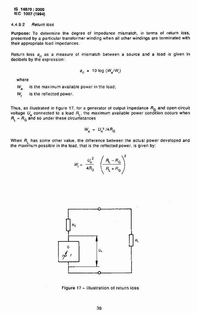
Purpose: To determine the degree of impedance mismatch, in terms of return loss,presented by a particular transformer winding when all othel windings are terminated withtheir appropriate load impedances.
Return loss arl as a measure of mismatch between a source and a load is given indecibels by the expression:
arl = 10 log ( kVa/wr)
where
Wa is the maximum available power in the load;
w, is the reflected power.
Thus, as illustrated in figure 17, for a generator of output impedance R= and open-circuitvoltage U. connected to a load RL, the maximum available power condition occurs whenRL = RG and so under these circumstances
Wa = U02 /4RG
When flL has some other value, the difference between the actual power developed and
the maximum possible in the load, that is the reflected power, is given by:
2
U02
()
RL - RGWr= —
4RG RL + RG
RL
G
+f
.—
Figure 17- Illustration of return loss
38
IS 14870:2000IEC 1007(1 994)
Hence the value of the return loss a,, in decibels is given by:
RL + RGarl = 20 log
IRL-RGI
Procedure: The basic bridge measurement circuit shown in figure 18 is set up with itselements equal to RG and the source voltage U and source frequency f are set to thespecified values. The initial bridge circuit loss registered on the calibrated decibelmeter Dwhen the terminals X are either short-circuited or open-circuited is recorded. Let this lossbe al. The terminated transformer under test is then connected to the terminals X and theloss indicated by D again recorded. Let this loss be a2.
The return loss of the transformer a(l in decibels is then given by the expression:
a~l = a2 – al
under test
Resistors R are frequency independent and matched, relative to each other, to within kO,l ‘A.R = R~ = R. (= typically 600 Q).
D is a decibel-meter, readily available for standard reference impedances such as 600Q.
Figure 18- Basic return loss test circuit
NOTES
1 The initial bridge circuit loss al should be close to 12 dB; the measured value is subject to the accu-
racy of the bridge circuit elements, particularly the source and calibrated decibel-mbter impedances.
..——
2 Suitable commercial measuring instruments incorporating the necessary network to provide a directmeasurement of return loss are in common use and may be used.
39
IS 14870:2000IEC 1007(1994)
Information to be stated:
a)
b)
c)
d)
e)
f)
impedance against which the return loss is to be measured, R;
winding connections;
load resistance RL or impedance ZL;
source voltage(s);
measurement frequencies;
d.c. current in output winding, if required.
.
4.4.10 Frequency response
Purpose: To determine the frequency response of a component when it is connected
between specified source and load impedances.
Procedure: The component together with its specified source and load impedances shallbe connected into a transmission measuring set, the basic circuit of which is the same asthat used for the insertion loss measurement of 4.4.9.1 (see figure 15). If specified, otherwindings shall be loaded and polarizing d.c~ applied. At the specified reference frequency,
fO, the attenuator shall be adjusted until U. is equal to UL as indicated by the frequencyselective voltmeter. The attenuator reading shall be noted. The change in attenuator read-
ing required to make UO equal to UL at any other frequency gives the relative gain or lossof the component at that frequency compared to the reference frequency. A plot of this
gain (10ss) against frequency constitutes a frequency response curve.
NOTE - Precautions such as screening, earthing and suppression of feedback by the use of co-axialchokes may be required, and corrections may be necessary to ensure that the response calculated fromthe reading of the calibrated attenuator gives the same resul~ as determined from the following formula:
20 log (u, /ufo)
where
U, is the output voftage at frequency f and
UtO is the output voltage at the reference frequency fo,
Information to be stated:
a)
b)
c)
d)
e)
f)
9)
component connections:
source impedance(s);
load impedance(s);
source voltage;
reference frequency fo;
frequency band or test frequencies;
polarizing current, if any.
4.4.11 Pulse characteristics
Purpose: To verify that, with a specified pulse applied to the input winding oftransformer, the correct output waveform is obtained when the transformer is connectedthe circuit for which it was designed.
40
ato
IS 14870:2000IEC 1007(1994)
Procedure: The specified input pulse shall be applied to the input winding with the outputwirrdings connected to the specified loads. The pulse obtained in the specified load shallbe displayed on an oscilloscope having a calibrated time base and voltage deflection. Thecharacteristics of the oscilloscope and its associated circuits shall be such that the pulsebeing displayed is not degraded because of excessive capacitance, insufficient bandwidth,etc.
The following measurements
a)
b)
c)
d)
e)
f)
9)
h)
i)
peak pulse amplitude,
pulse duration, td;
pulse rise time, tr;
pulse fall time, tf;
pulse droop;
overshoot;
backswing;
return backswing;
recovery time.
shall be made as required by the relevant specification:
Um;
Information to be stated:
a) input peak pulse amplitude, duration, rise time, fall time, droop and repetitionfrequency;
b)
c)
d)
load impedance(s);
output characteristics to be measured;
ambient temperature.
4.4.12 Voltage-time product rating
Purpase: To verify that the voltage-time product rating of a component (see 3.7) is withina stated limit.
NOTE – For applications Involwng bi-directional pulses, -such as switched-mode power supplies, thevoltage-time product will not be the same as for unl-directional pulses.
Procedure: When the specified test temperature differs from ambient, the component
shall be heated in an oven until thermal equilibrium is obtained at the specified tempe-rature.
If the transformer application involves a direct current in any of its windings the test shallbe conducted with rated d.c. ampere-turns applied through a suitable impedance toprevent pulse-loading effects.
A rectangular voltage pulse of peak amplitude Urn shall then be applied to the specifie-dwinding for a pulse duration td and the corresponding magnetizing current monitored.An example of a suitabl’e test circuit is shown in figure 19. (See also clause 16 andappendix M of IEC 367-1. )
41
IS 14870:2000IEC 1007(1994)
I G I T 1
u N
R,
+1 I
R, isaprecision non-reactive resistor causing avoitage drop not exceeding 1 YOof Um.
Figure 19- C-ircuit for verifying voltage-time product rating:measurement without bias and with single pulses
Requirement: The magnetizing current shall not exceed a specified percentage of the
extrapolated linear portion of the current waveform at time td,that is, the non-linearity ofthe magnetizing current shall not exceed a specified value (see figure 20).
Information to be stated:
a) test temperature;
b) pulse amplitude, U~ (volts)*;
c) pulse duration, fd (s)*;
d) if required, the value of superimposed d.c., its polarity and the terminationsbetween which the d.c. is to flow;
e) maximum permissible non-linearity of magnetizing current.
_ ...—
.
According to the stated voltage-time product rating for the component
42
IS 14870:2000IEC 1007(1994)
ACurrent
L
,%n
td Time, t
im &Non-linearity= — x 100; maximum non-linearity= — Xloo
tin fin
Figure 20- Non-linearity of magnetizing current
NOTE - Several putses might be necessary to obtain the required magnetic state of the transformer.
Self -heating.of core and winding should be avoided.
4.4.13 Tots/ harmonic distortion
Purpose: To verify that the harmonic distortion produced by the component when asso-
ciated with its specified source and load impedances does not exceed the specifibd limits.
Procedure: A voltage at the specified frequency shall be applied such that the sp~ifiedoutput is achieved. The total harmonic content of the supply shall be at least ten timesless than the output limit specified. When specified the appropriate direct current shallalso be passed through the appropriate winding during the test. The total harmonicdistortion shall then be determined by the use of either:
a) harmonic distortion measuring equipment giving a direct reading of total harmonicdistortion, or
b) by the measurement of all sign~icant harmonic voltages up to and including theseventh followed by the computation of total harmonic distortion from the followingexpression:
43
IS 14870:2000IEC 1007(1 994)
‘/2
()
x
7 100*uf2 x_ 70
n Uf ,
where
f, is the fundamental supply frequency;
fn is the nth harmonic frequency of the supply;
qn is the voltage at any particular harmonic frequency.
NOTE - The total harmonic distortion may also be expressed in decibels relative to the fundamental
Information to be stated:
a)
b)
c)
d)
e)
source impedance;
load impedance;
supply frequency;
output voltage at supply frequency;
polarizing current (if any).
4.4.14 Voltage regulation
Purpose: To establish the extent of voltage variation on specified winding(s) from theno-load condition to that at which the output winding(s) are simultaneously carrying the fullload current.
Procedure: The specified input windings shall be energized at the rated voltage andfrequency and the voltage across each winding shall be measured when all outputw“indings are open-circuited. The specified loading shall be applied Ior the specified periodor, in the absence of a statement, until thermal stability is achieved. The voltage acrosseach winding shall be measured while the output windings are carrying their specified loadcurrents. The percentage voltage regulation shall be calculated for each output windingusing the following formula:
Ua - Ub
x 100Ua
where
Ua is the voltage across the winding without load;
Ub is the voltage across the winding with load connected.
The voltage regulation shall be within the specified limits during and at the end of the test.
Information to be stated:
a)
b)
input -supply condition;
output winding(s) load conditions;
44
-—
IS 14870:2000IEC 1007(1994)
c)
d)
e)
f)
9)
duration of test;
details of duty cycle if other than continuous;
atmospheric conditions if other than standard;
details of moufrting if other than on a thermally non-conducting surface;
voltage regulation limits during and at the end of the test.
4.4.15 Temperature rise
NOTE - The following tests are intended for proving the performance of series production components.A thermal probe (see 4.4.16) may be used, if required, as an alternative method for development items.
4.4.15.1 Method utilizing the change in d.c. resistance of a winding
Purpose: To determine the mean temperature rise of a component when it is subjected toa continuous duty cycle in a specified environment.
Procedure: The component under test shall be energized and loaded as specified in thedetail specification. The d.c. resistance of the specified winding(s) shall be determined asin 4.’4.4 .1.
When thermal stability is achieved - i.e. when any change in input power does not exceed2 Y. during a continuous period of 15 rein, the power supply and load shall be dis-connected and the d.c. resistance remeasured as in 4.4.1.1 with minimum delay. Minimumdelay is necessary to ensure that the resistance measurement represents as closely aspossible the highest temperature reached by the component during its operation underload. If required a cooling curve shall be developed and extrapolated back to establish theresistance R2 at the instant of disconnection,
The temperature rise of the winding(s) shall be calculated using the following formula:
R2er=; (os+k)-($+k)
1
where
0s is the ambient temperature at start of test (in ‘C);
Elf is the ambient temperature at end of test (in “C);
0, is the winding temperature rise (in “C);
RI is the winding resistance immedi-ately before energization (in Q);
R2 is the winding resistance immediately after disconnection of the energizingsource (in Q);
k is related to the thermal coefficient of resist ivity: the value for copper shall be
taken as 234,5 and for aluminium as 228,1 for the purpose of this standard .
Information to be statf?d:
a) information required by a) and b) of 4.4.1.1;
45
IS 14870:2000IEC 1007(1994)
b) for conductor materials other than copper or aluminium the appropriate value of theconstant k;
c) mounting details;
d) environment;
e) input supply conditions as appropriate:
1) voltage and frequency,
2) pulse duration and repetition frequency,
3) polarizing current, ripple voltage and frequency;
f) output load(s).
NOTE - In some cases, adequate specification of loading may necessitate more detailed information, suchas circuit diagrams and associated component values. ,
4.4.15.2 Method using an additional series-opposing bifilar winding
Purpose:
a) to measure temperature rise without interruption of power;
b) to measure rate of temperature rise.
Procedure: A bifilar winding is wound on or applied to the component with its two partsconnected in series - opposition. The d.c. resistance of this winding shall be measured asin 4.4.1.1 and the temperature rise determined as in 4.4.15.1.
NOTES
1 This method may be used when there is an accessible free core or winding surface on which a suitablebifilar winding can be placed,
2 The application of thermal insulation to the bifilar winding may enable an estimate of internal compo-nent temperatures to be obtained
3 This method may be adapted to the evaluation of prototypes by installing the bifilar winding betweenthe functional windings of the component,
4 Where the observed resistance varies, according to whether the component under test is energized
or not, the reading corresponding to absence of power should be used. The difference between the two
conditions is attributable to eddy current effects.
Information to be stated:
a) details of additional bifilar winding, including position;
b) details of thermal insulation if required;
c) other information as in 4.4.15.1.
4.4.16 Surface temperature
Purpose: To determine the surface temperature of a transformer or inductor subjected to
a continuous load within an environment specified in the detail specification.
--—
.,
Procedure: The conditions of test and procedures of 4,4.15.1 of this standard shall be
appiied untii thermal equilibrium is achieved; i.e. until any change in input power does notexceed 2 O/. during a continuous period of 15 min.
46
IS 14870:2000IEC 1007(1994)
The surface temperature shall then be measured with a thermal probe of low thermalconductivity and mass at a specified point on the component surface.
The surface temperature shall be recorded.
NOTES
1 The maximum surface temperature may be determined by scanning the component surface.
2 Measured values may be affected by:
a) the thermal resistance between probe and component surface;
b) electromagnetic fields, to which some probes are sensitive.
WARNING - Electrical shock hazard. Precautions must be taken physically and elec-
trically to isolate the operator of the thermal probe from live or conducting parts of thecomponent under test.
Information to be stated:
a) information required by items c), d), e) and f) of 4.4.15.1;
b) maximum surface temperature;
c) specific points of measurement required by the customer.
4.4.17 Phase test (po/arity,J
Purpose: To establish that the windings are of the correct phase relative
Procedure 1: The windings whose relative phases are to be examined
to one another.
are connected inseries. A supply of suitable voltage and frequency is connected to one of the test wind-ings, and voltage measurements are made across the individual windings and their series
assembly.
The addition of the voltages across the individual windings is compared with the voltage
across the combined series winding.
For windings properly assembled with the phases (polarities) shown in figure 21, the
following relationship is true:
U3=U1+U2
For windings with opposite polarity:
U3 = IU1-U21
47
—
IS 14870:2000IEC 1007(1994)
Information
Figure 21- Phase (polarity) test using voltage measurement
to be stated:
a) terminations to be connected together;
b) terminations between which the phase is to be determined.
Procedure 2: Using the bridge circuit and associated procedures given in Procedure 2 of4.4.7.1, verify the relative phase of the windings to be tested.
NOTES
1 Incorrect polarity of AB relative to BC will result either in a balance at a value of P:Q different from that
specified or failure to achieve a balance (see figure 11 ).
2 This procedure may not be feasible with some polyphase components.
Information to be stated:
a)
b)
c)
d)
winding connections giving the correct polarity of winding AB relative to winding BC;
the voltage transformation ratio limits;
test frequency and voltage;
if required, the approximate values of RI and R2.
Procedure 3: The windings
series, as specified, and the(see 4.4.4.1).
whose relative phases are to be e~amined are connected in
inductance of the assembly is measured on a suitable bridge
. ——
.
The result of this measurement is compared with the value calculated from the
inductances of the individual windings as determined on the same bridge,
48
IS 14870:2000IEC 1007(1994)
Thus, for the simplest case of two windings having inductance L, and L2, the seriesconnected windings will have a total measured inductance of:
L1+L2*2k G
where k is the coefficient of coupling, and the positive sign is associated with the series-aiding corm’kiction of the windings.
Reversal of the connection to one winding will thus produce a variation of 4/( ~~.
NOTE - This method may not be suitable if the individual winding inductances are widely different, or if thecoefficient of coupling between the test windings is small.
Information to be stated:
a)
b)
c)
terminations to be connected together;
terminations between which the phase is to be determined;
test frequency and voltage.
Procedure 4: One end of each winding shall be connected to the common terminal of atwo-channel oscilloscope. A supply of suitable voltage and frequency shall be connectedto the Y1 input of the oscilloscope and to the free end of one winding. Each other free endor tap shall be connected in turn to the Y2 input terminal and the waveforms examined toestablish their phase relationships.
Information to be stated:
a) terminations to be connected together;
b) terminations between which the phase is to be determined.
4.4.18 Screens
NOTE - Sometimes the word “shield” is used as an alternative, In Engllshrexts
4.4.18.1 Capacitance test for screens
Purpose: To verify the electrostatic (shielding) effectiveness of each screen.
Procedure: On each side of the screen the windings shall be short-circuited and
connected together. If the screen is isolated it shall be connected to the core (or case ifthe core is not accessible) for the test unless otherwise specified.
Measurement of the direct capacitance from the windings on one side of the screen tothose on the other shall be made by Procedure 2 of 4.4.6.2. Care shall be taken to avoidthe effect of extraneousobtained with the screen
parasitic capacitance. The results shall be compared with thosedisconnected.
—
49
IS 14870:2000IEC 1007(1994)
Informat-ion to be stated:
a)
b)
c)
winding connections;
screen connection if other than to the core or case;
ratio of the capacitances: screen connected, to screen disconnected.
4.4.18.2 Safety screens
NOTE - Sometimes the term ‘isolating screen- is used as an alternative to ‘safety screen..
Purpose: To verify the existence and construction of any safety screens.
Procedure: The component shall be visually inspected by disassembly to verify theexistence of any safety screens and the quality of their construction, taking into accountthe material and thickness of the screen, its width in relation to the width of the windingand its relative positioning, the cross-sectional area of the wire joining the screen to theexternal terminal and the quality of its joint to the screen.
If required, this destructive test shall be substituted by visual inspectionfacturing stage, when screen and joints are visible.
A final check on completed components shall be made by means of
dielectric insulation tests (see 4.4.18.1 and 4.4.2).
during the manu-
capacitance and
Information to be stated:
a) whether test is to becompleted component;
carried out during manufacture or as a destructive test on a
b) screen material and thickness;
c) screen width;
-d) cross-sectional area and material of wire connecting screen to its connectingterminal and method of connection;
e) terminal size and material.
4.4.19 Noise
4.4.19.1 Acoustic noise
Purpose: To determine the level of audible noise radiated to the environment by the
component under specified conditions.
Procedure: Whenever possible the component to be tested shall be fastened (bolted,
soldered, etc.) to the chassis or other mechanical structure on which it is to be perma-nently mounted during its operation. The component shall then be placed in a chamberfree from any noise-reflecting sutiace except that of the chassis or mechanical structure
that contains the mounted component. The level of the background noise (see 3.8) in thechamber-shall be at least 4 dB(A) and preferably 9 dB(A) lower than the combined soundlevel of the component and the chamber background noise.
The background noise level shall be taken to be the average of the
immediately before and immediately after the component is tested atspecified.
50
measurements taken
each of the locations
IS 14870:2000EC 1007(1994)
If the background level is such that the difference in dB(A), between the mean combinedsound level of the component plus the background and the mean background level is lessthan 10 dB(A), but not less than 4 dB(A), the corrections shown in the table below shall.beapplied. If this difference is less than 4 dB(A) the test shall not be accepted and effortsshall be made to lower the background noise level.
Sound-level corrections for audible noise tests
Difference in dB(A) between the mean Corrections in dB(A) to be subtractedcombined sound level of the from the mean combined sound level of
component plus the background the component plus the backgroundand the mean background alone to obtain sound level of the component
4 2,25 1,76 1,37 1,08 0,89 0,6
10 0,4Over 10 0,0
The component shall be on no-load and shall be energized at rated frequency and ratedvoltage from a source of specified waveform connected-to the specified terminations.
Sound levels shall be measured with an instrument that is in accordance with IEC 651, oftype 1F.L (F - fast response indication; L, - for laboratory use) and having a minimum read-
ing not less than 40 dB(A). The frequency weighting characteristic A of the instrumentshall be used.
“Measurements shall be taken with the probe of the sound-level meter loc~ted at thespecified distance which shall be not greater than 0,.3 m from the surface of which theacoustic radiation is to be measured. The readings shall be taken at the centre of each ofthe four vertical plane surfaces and at the centre of the top horizontal surface borderingthe component. The surfaces are assumed -to be those from which sound is radiated andare determined by faces of the hexahedron describing the component contour, excludingbushings, turrets, lugs, etc.
The average sound level of component plus background or background alone is calculated
from the arithmetic mean of the sound levels measured as above. The average soundlevel of the component is calculated taking the corrected sound-level values for eachmeasuring position.
Information to be stated:
a)
b)
c)
d)
mounting details;
distance of sound-level meter from test surfaces;
winding connections;
voltage and frequency of component energization.
51
IS 14870:2000
IEC 1007(1994)
NOTE - In the cases of components that are constructed with auxlllary elements such as forced-air or oilcoolers - e.g., for components of large dimensions andlor possessing distinctly directional acousticradiation, the acoustic noise measurement should be performed according to IEC 551.
4.4.19.2 Electromagnetic noise
Electromagnetic noise concerns the emission or the reception of unwanted signals havingassociated electric and magnetic fields, throughout the frequency spectrum used for powertransmission and communications. Since electromagnetic noise concerns complete equip-ment rather than individual components, no test methods are included in this standard.
Specifications for the limits of emitted noise and for immunity of equipment in thepresence of noise are dealt with under the general heading of electromagnetic com-patibility (EMC)*.
4.4.20 Corona test
The Corona test shall be made in accordance with IEC 270,
‘NOTE - IEC 44-4 covers routine tests for this specific application
4.4.21 Magnetic fields
4.4.21.1 Magnetic shielding
Purpose: To determine the influence of an external magnetic field on a component.
Procedure: The component shall be placed in a uniform alternating magnetic field of the
specified strength and frequency and the voltage across the specified winding shall bemeasured with a voltage detector having an input impedance of not less than 1 MQ. The
component shall be rotated and the maximum voltage recorded.
NOTE - A uniform field is produced by a Helmholtz structure (see figure 22) with a coil diameter at least
twice the maximum dimension of the component. With the coils connected in series-aiding, a simplified
formula for the field strength H in A/m is:
0,716 P/iH= —
where
N is the number of turns of each coil;
r is the coil radius (i.e. coil axial spacing) (in metres);
i is the peak current (In amperes)
Dimensionsare given in
of Helmholtz structure for components of up to 275 mm maximum dimensionfigure 22, each coil consisting of 1 500 turns of 0,2 mm diameter wire.
. ..—
.
Committees involved in the publication of EMC documents include: TC 65: Industrial-process measurementand control; TC 77. Electromagnetic compatibility between electrical equipment including networks; andCISPR: International Special Committee on Radio Interference. (Details of the publications are given in theIEC Yearbook.)
52
IS 14870:2000IEC 1007(1994)
Information to be stated:
a) magnetic field strength in amperes/metre;
b) frequency of the alternating magnetic field;
c) winding whose output voltage is to be measured;
d) axes of rotation.
t
Mean060
——
being measured
Figure 22- Helmholtz structure
4.4.21.2 Magnetic influence (compass safe distance)
Purpose: To determine the minimum distance from a compass at which a transformer orsimilar wound component may be placed to limit the deviation to a stated value under allconditions of operation (see 3.9).
Conditions of measurement: Measurements shall be made in a uniform magnetic field.If the horizontal comp?nent of this field has a value outside the limits 13 A/m to 16 A/m
then the compass safe distance, Dc~ (in metres), shall be calculated from the followingexpression:
53 “
IS 14870:2000EC 1007(1994)
D - 14,4 DmlHCs “
where
Dm is the measured distance (in metres);
H is the actual field strength (in amperes/metre).
Procedure: The test area shall be marked out with magnetic N-S and E-W lines and asuitable magnetometer placed at the intersection of these lines. The magnetometer (whichmay be a compass) shall be capable of being read to an accuracy of one-fifth of a degreeand shall possess a corresponding sensitivity.
The component under test shall be placed on the E-W linemagnetometer that gives a deviation of approximately 2°.
Experiments shall be made to -determine the combination of
at a distance from the
attitucfe and degree ofenergization that gives the maximum deviation of the magnetometer. This combinationshall be maintained while the component is moved outwards along the E-W line until themagnetometer deviation is approximately 0,5°. From readings taken at intervals during thismovement a curve shall be plotted showing magnetometer deviation against ctktance.
As a check on experimental error a curve shall also be plotted to correspond to an inwardmovement of the component. The two curves, which should be substantially coincidental,shall be used to establish accurately the distance at which a 10 deviation of themagnetometer is experienced. This distance shall be recorded as the compass safedistance for the component.
The compass safe distance ofeffect shall be measured if socation and its value declared.
Information to be stated:
equipment that produces a significantrequired along other axes defined by
directional magnetic,the relevant specifi-
- the connections to be made to the component under test.
4.4.21.3 Magnetic radiation
Purpose: To determine the extent of the magnetic influence of a component on its environ-ment.
Procedure: The component shall be located .at the centre of a non-metallic (insulating)cube fixture that will permit the centre of a search coil to be moved freely over thesurfaces of the whole area of the external faces of the cube.
Cube dimensions, together with corresponding search coil data, shall be as follows:
54
IS 14870:2000IEC 1007(1 994)
Operating Cube fixturefrequency band dimension
Search coil data
mm
10 Hz to 150 HZ 300 1 500 turns of enamelled copperwire, 0,315 mm diameter, woundinto a coil, 285 mm internaldiameter, 75 mm long
150 f+z to 30 kHz 150 Single-turn loop of 1 mm wire,150 mm diameter
30 kHz to 5 MHz 75 Single-turn loop of 1 mm wire,75 mm diameter
Above 5 MHz 37 Single-turn loop of 0,71 mm wire,37 mm diameter
With the component energized and loaded as specified, the external faces of the cubic fixture shall be scanned an~ the maximum peak output voltage indicated by means of a highimpedance detector connected across the search coil shall be no”ted. This value shall not
exceed the limit specified in the relevant specification.
Information to be stated:
a) alternating voltage level(s);
b) measuring frequency (ies);
c) load impedance(s);
d) if required, the limit values of the peak voltage across the search coil.
4.4.22 Inrush current
Since it is considered that inrush current is primarily significant for completb equipmentrather than individual components, no test methods are included in this standard.
4.5 Environmental test procedures
4.5.1 General
4.5.1.1 Capability approval
The test conditions together with the initial, final and intermediate measurements to bemade shall be as prescribed by the relevant schedule in a future IEC standard.
4.5.1.2 Quality conformance inspection
Where environmental tests are prescribed by a detail specification, use can be made of
the procedures (if applicable) listed below, which, with the exception of the tests for firehazard, are taken from IEC 68-2.
..—
NOTE - Users should ensure that they are in possession of the appropriate issued texts
55
IS 14870:2000IEC 1007 (1994)
Alternatively the detail specification writer may choose the test conditions from the optionsgiven in the relevant part of IEC 68.
The severity of the test, and the initial, final and intermediate measurements to be madeshall be given in the quality conformance schedule of the detail specification.
4.5.2 Soldering
IEC 68-2-20 Test T. The appropriate test method of test Ta, as specified in the detailspecification, shall be used for the determination of the solderability of wire and tagterminations.
NOTES
1 For components intended exclusively for printed wiring applications, only method 1 of test Ta should
be used.
2 Where the resistance of components to soldering heat is specified, method 1B of test Tb applies.
3 The relevance of IEC 68-2-58 Test Td should be noted for application to such devices.
4.5.3 Robustness of terminations and integral mounting devices
IEC 68-2-21 Test U. Tests Ual, Ua2, Ub, Uc or Ud shall be used as specified in the detail
specification according to the type of termination. As a re-suit of the test there shall be novisible damage to the termination, fixing or sealing and connections to the terminations
shall be satisfactory when tested in accordance with 4.4.1.2.
4.5.4 Shock
CEI 68-2-27 Test Ea and guidance.
4.5.5 Bump
CEI 68-2-29 Test Eb and guidance.
4.5.6 Vibration (sinusoidal]
CEI 68-2-6 Test Fc and guidance.
4.5.7 Acceleration, steady state
CEI 68-2-7 Test Ga and guidance.
4.5.8 Rapid change of temperature (thermal shock in air)
IEC 68-2-14 Test N. Test Na as specified.
4.5.9 Sealing
IEC 68-2-17 Test Q. Test Qc or Qd as specified,
....—
.
4.5.10 -C/imatic sequence
The following test sequence shall be applied:
56
IS 14870:2000IEC 1007(1994)
a) Dry heat, test Ba. The specimen shall be subjected to test Ba of IEC 68-2-2 at up-per category temperature. Duration 16 h.
b) Interval 1. An interval not exceeding 72 h is permitted at this stage of the proce-dure; during the interval the specimen shall be kept at a temperature between 15 “Cand 35 ‘C under normal laboratory conditions.
c) Damp heat (cyclic), test Db. Any specimen with a climatic category of -/-/10, -/-/21or –/–/56 shall be subjected to test Db of IEC 68-2-30 at severity b) 55 “C for 1 cycle,variant 1 followed by a recovery period of between 1 h 30 to 2 h.
d) Cold, test Aa. Immediately after the damp heat cycle of c) the specimen shall besubjected to test Aa of IEC 68-2-1 for a period of 2 h at lower category temperature.
e) Interval 2. An interval not exceeding 72 h is permitted at this stage of the proce-
dure; during the interval the specimen shall be kept between 15 ‘C and 35 “C undernormal laboratory conditions.
f) Low air pressure, test M. If required (see note), any specimen with a climatic cate-gory 40/-/-, 55/-/- or 65/-/- shall be subjected to IEC 68-2-13 Test M at the
prescribed degree of severity. The Iow-Wessure conditioning shall be carried outbetween 15 “C and 35 “C for 1 h, unless otherwise specified in the detail specification.
g) Interval 3. An interval not exceeding 72 h is permitted at this stage of the procedureonly if the low air-pressure test of f) has been carried out; during the interval the speci-men shall be kept between 15 ‘C and 35 ‘C under normal laboratory conditions.
h) ,Damp heat (cyclic), test Db. Specimens of category -/-/1 O, -/-/21 and -/-/56 shallthen be subjected to test Db of IEC 68-2-30 at severity b) 55 “C for 1 cycle, variant 1.
Where specified the specimen shall be removed from the chamber after the specifiednumber of cycles, shaken to remove droplets of water and within 15 min shall besubjected to relevant electrical and mechanical tests.
I) Recovery. The specimen shall be allowed to recover for between 1 h 30 and 2 hunder standard conditions for recovery.
NOTE - For capability approval the low air. pressure test is optional.
4.5,11 Damp heat, steady state
IEC 68-2-3 Test Ca.
4.5.12 Dry heat
IEC 68-2-2 Test B,
4.5.13 Mould growth
IEC 68-2-10 Test J and guidance.
4.5.14 Salt mist, cyclic (sodium chloride solution)
IEC 68-2-52 Test Kb.
57
-
IS 14870:2000IEC 1007 (1994)
NOTE - Where test Kb is specified and it is wwhed to use a salt solution which corresponds to a marineenvironment, the following composition IS recommended”
sodium chloride NaCI 26,5 g
magnesium chloricle MgC12 2,4 g
magnesium sulphate MgS04 3,3 g
calcium chloride CaC12 1,1 g
potassium chloride KCI 0,73 g
sodium bicarbonate NaHC03 0,20 g
sodium bromide NaBr 0,28 g
distilled water to make up 1 I
(The above masses shall be accurate to within *1 O %; they refer to anhydrous salts of laboratory reagentgrade. )
.. .—
.4.5.15 Sulphur dioxide test for contacts and connections
IEC 68-2-42 Test Kc.
4.5.16 Fire hazard
Test for fire hazard shall be selected from IEC 695.
NOTE - IEC 695-2-2 Needle-flame test is more appropriate for small components. The Bunsen-type flametest of IEC 695-2-4 is more appropriate for larger components.
4.5,17 Immersion in cleaning solvents
IEC 68-2-45 Test XA and guidance.
4.6 Endurance test procedures
4.6.1 Short-term endurance (load run)
Purpose: To assess the capability of the component to function satisfactorily duringcontinuous operation or during duty cycles specified in the detail specification.
Procedure: The component shall be free-standing on a surface of low thermal conduc-tivity, unless otherwise specified in the detail specification. *
a) For transformers, separate loads shall be connected to each winding as specified inthe detail specification. The value of these loads shall be such that the maximum ratedpower of each winding will be dissipated, unless-otherwise specified in the detail specifi-
cation.
An appropriate power supply shall be connected to the input winding and applied con-
tinuously for 6 h under standard atmospheric conditions, unless otherwise specified inthe detail specification. During the load run, the load(s) shall be adjusted as necessaryto ensure that the specified load conditions are maintained.
b) For inductors, the rated ripp!e voltage shall be applied, and the rated polarizingcurrent passed continuously for 6 h under standard atmospheric conditions, unlessotherwise specified in the detail specification. During the load run, the supply orsupplies shall be adjusted as necessary to ensure that the rated conditions aremaintained.
IS 14870:2000IEC 1007(1994)
Information to be stated in the detail specification:
a) the input supply conditions as appropriate:
rated voltage and frequency;
rated pulse duration and repetition frequency;
rated polarizing direct current, ripple frequency and voltage;
b) the load conditions of the output winding(s);
c) the duration of test, if other than 6 h;
d) the details of the duty cycle, if other than continuous;
e) the atmospheric conditions for test, if other than standard;
f) the details of mounting, if other than free-standing on a surface of low thermal
conductivity;
g) the requirements to be satisfied during and at the end of the test.
4.6.2 Long-term endurance (life test)
Purpose: To determine the capability of a component to withstand repetitive cycles ofoperation under the load conditions specified in the detail specification.
Procedure: The component shall be free-standing on a surtace of low thermal conduc-
tivity, unless otherwise specified in the detail specification.
a) For transformers, separate loads shall be connected to each winding as specified inthe detail specification. The value of these loads shall be such that the maximum ratedpower of each winding will be dissipated, unless otherwise specified in the detail specifi-cation.
b) For inductors, the rated ripple voltage shall be applied and the rated polarizingcurrent shall be passed through the winding.
Components shall be subjected to a minimum of five endurance cycles per week to atotal of 85 cycles. Each of the cycles shall consist of 24 h, during which time the compo-nents shall be energized at upper category temperature for 20 h continuously, and for
the remaining 4 h the component shall be kept without excitation under standard atmos-pheric conditions
Information to be stated in the detail specification:
a) the input supply conditions as appropriate:
- rated voltage and frequency;
- the rated pulse duration and repetition frequency;
- the rated polarizing direct current, ripple frequency and voltage;
b) the load conditions of the output winding(s);
c) the details.of the duty cycle, if other than continuous;
d) the details of mounting, if other than free-standing, on a surface of low thermal con-ductivity;
e) the requirements to be satisfied during and at the end of the test
59
Bureau of Indian Standards
BIS is a statutory institution established under the Bureau of Indian Stan&rds Act, 1986 to promoteharmonious development of the activities of standardization, marking and quality certification of goodsand attending to connected matters in the country.
Copyright
BIS has the copyright of aIl its publications. No part of these publications may be reproduced in any formwithout the prior permission in writing of BIS. This does not preclude the free use, in the course ofimplementing the standard, of neeessary details, such as symbols and sizes, type or grade designations.Enquiries relating to copyright be addressed to the Director (Publications), BIS.
Review of Indian Standards%..—
Amendments are issued to standards as the need arises on the basis of comments. Standards are alsoreviewed periodically; a standard -along with amendments is reaffirmed when such review indicates that -’.>
no changes are needed; if the review indicates that changes am needed, it is taken up for revision. Users!!
of Indian Standards should ascertain that they are in possession of the latest amendments or edition by+
referring to the latest issue of ‘BIS Handbook’ and ‘Standards: Monthly Additions’.
This Indian Standard has been developed from Doc : No.: L,TD Is ( 849 ).
I
Amendments Issued Since Publication
Amend No. Date of Issue Text Affected
i
BUREAU OF INDIAN STANDARDS
Headquarters:
Manak Bhavan, 9 Bahadur Shah .Zafar Marg, New”Delhi 110002 Telegrams : ManaksansthaTelephones :3230131, 3233375, 3239402 (Common to all offices)
Regional Offices : Telephone
Central : Manak Bhavan, 9 Bahadur Shah Zafar Marg
{
3237617NEW DELHI 110002 3233841
Eastern : 1/14 C. I.T. Scheme VII M, V. I. P. Road, Kankurgachi