IS 15328:2003 W+* mmqow=i’idmm rN w fin llw~d WV HICIIRW \ r Iq& (Wr.ti.-q) * - mm Indian Standard UNPLASTICIZED NON-PRESSURE POLYVINYL CHLORIDE ( PVC-U) PIPES FOR USE IN UNDERGROUND DRAINAGE AND SEWERAGE SYSTEMS — SPECIFICATION lCS 83. 140.30;93.030 . Jldy 2003 0 BIS 2003 BUREAU OF INDIAN STANDARDS MANAK BHAVAN, 9 BAHADUR SHAH ZAFAR MARG NEW DELHI 110002 Price Group 10
Transcript
IS 15328:2003
W+*
mmqow=i’idmmrN w finllw~d WV HICIIRW
\ rIq& (Wr.ti.-q) * - mm
Indian Standard
UNPLASTICIZED NON-PRESSURE POLYVINYLCHLORIDE ( PVC-U) PIPES FOR USE IN
UNDERGROUND DRAINAGE AND SEWERAGESYSTEMS — SPECIFICATION
lCS 83. 140.30;93.030
.
Jldy 2003
0 BIS 2003
BUREAU OF INDIAN STANDARDS
MANAK BHAVAN, 9 BAHADUR SHAH ZAFAR MARG
NEW DELHI 110002
Price Group 10
Plastic Piping System Sectional Commitlee, CED 50
FOREWORD
This Indian Standard was adopted by the Bureau of Indian Standards, after the draft finalized by the PlasticPiping System Sectional Committee had been approved by the Civil Engineering Division Council.
This standard has been prepared with a view to providing guidance for the manufacture and selection ofPVC-U pipes for the conveyance of domestic sewage, industrial waste and surface water ( other than potablewater ).
PVC-U pipes for conveyance of potable water are covered in IS 4985:2000 ‘U.nplasticized PVC pipes for potablewater supplies — Specification ( third revision )’.
In the formulation of this standard, due weightage has been given to bring it in line with InternationalStandards as well as market situations and practices prevailing in India and considerable assistance hasbeen derived from the following International Standards published by International Organization forStandardization:
1S0 580:1990
1S0 1167:1996
1S03127 :1994
1S0 4065:1996
1s04435 :1991
1S03604-1976
Iso/DIs 3845-1995
ISOiDIS 13846-1995
Injection moulded unplasticized ( polyvinyl chloride ) ( PVC-U ) fittings — Oventest — Test method and basic specifications
Thermoplastics pipes for the transport of fluids — Resistance to internal pressure— Test method
Thermoplastic pipes — Determination of resistance to external blows
Unplasticized ( polyvinyl chloride) ( PVC-U ) pipes and fittings for buried drainageand sewerage systems — Specification
Fitting for unplasticized polyvinyl chloride ( PVC-U) pressure pipes with elasticsealing ring type joints — Pressure test for Ieakproofhess under conditions of externalhydraulic pressure
Plastics piping systems — Elastomeric-sealing-ring-type socket joints for use withunplasticized ( polyvinyl chloride) ( PVC-U ) pipes — Test method for leaktightnessunder internal pressure and with angular deflection
Plastics piping systems — End-load-bearing and non-end-load-bearing assembliesfor thermoplastics pressure piping — Test method for long-term leaktightness underinternal water pressure
The composition of the Committee responsible for formulation of this standard is given in Annex G.
For the purpose of deciding whether a particular requirement of this standard is complied with, the finalvalue, observed or calculated, expressing the result of a test or analysis, shall be rounded off in accordancewith 1S 2: 1960 ‘Rules for rounding off numerical values ( revised)’. The number of significant places retainedin the rounded off value should be the same as that of the specified value in this standard.
IS 15328:2003
Indian Standard
UNPLASTICIZED NON-PRESSURE POLYVINYLCHLORIDE ( PVC-U) PIPES FOR USE IN
UNDERGROUND DRAINAGE AND SEWERAGESYSTEMS — SPECIFICATION
1 SCOPE
This standard specifies the requirements of plainended or equipped with integral sockets for eithersolvent-cement welding or for jointing withelastomeric sealing rings pipes made of unplasticizedpolyvinyl chloride ( PVC-U ) of nominal outsidediameters ranging from 110 mm up to and including630 mm, intended for underground (buried) non-pressure gravity drain and sewer applications fortransportation of soil and waste discharge of domesticorigin, surface water ( storm water ) and industrialeffluent.
In the case of industrial effluent, chemical andtemperature resistance and resistance to suspendedmatter have to be taken into account.
2 REFERENCES
The following standards contain provisionswhich, through reference in this text, constituteprovisions of this standard. At the time of publication,the editions indicated were valid. All standards aresubject to revision and parties to agreements basedon this standard are encouraged to investigate thepossibility of applying the most recent editions of thestandards indicated below:
IS No.
4905:1968
4985:2000
5382:1985
12235
(Part 1): 1986
(Part 5):1986
(Part 8):1986
Title
Methods for random sampling
Unplasticized PVC pipes forpotable water supplies —Specification ( third revision )
Specification for rubber sealingrings for gas mains, water mainsand sewers (first revision )
Methods of test for unplasticizedPVC pipes for potable watersupplies:
Method of measurement of outsidediameter
Reversion test
Internal hydrostatic pressure test
IS No. Title
14182:1994 Solvent cement for use withunplasticized polyvinyl chloride pipeand fittings — Specification
3 TERMINOLOGY
3.0 For the purpose of this standard, the followingdefinitions shall apply.
3.1 Nominal Size ( DN) — The numerical designationfor the size of a pipe, other than a pipe designated bythread size, which is a convenient round numberapproximately equal to the manufacturing dimensionin millimetres.
3.2 Nominal Outside Diameter (da) —The specifiedoutside diameter in millimetres assigned to thenominal size.
3.3 Outside Diameter at Any Point ( d,) — The valueof the measurement of the outside diameter of a pipethrough its cross-section at any point of Ihe pipe,rounded off to the next higher 0.1 mm.
3.4 Mean Outside Diameter ( dem) — The quotientof the outer circumference of a pipe and 3.142 ( n )in any cross-section, rounded off to the nexthigher 0,1 mm.
3.5 Minimum Mean Outside Diameter ( dem,~in ) —The minimum value of the mean outside diameter asspecified for a given nominal size.
3.6 Maximum Mean Outside Diameter ( dem,~ax) —
The maximum value of the mean outside diameter asspecified for a given nominal size.
3.7 Inside Diameter of a Socket (d, ) — The valueof the measurement of the inside diameter of thesocket at any point in any cross-section of the socket.
3.8 Mean Inside Diameter of a Socket (d,m) — Thearithmetical mean of four measurements, taken at 45°to each other, of the inside diameter of the socket inthe same cross-section of the socket.
3.9 Out-of Roundness ( Ovality ) — The differencebetween the measured maximum and the measuredminimum outside diameter in the same cross-sectionof the pipe.
1
IS 15328:2003
3.10 Nominal Wall Thickness (en ) — A numericaldesignation of the wall thickness of a component whichis a convenient round number, approximately equalto the manufacturing dimension in millimetres.
3.11 Wall Thickness at Any Point(e) — The valueof the measurement of wall thickness at any pointaround the circumference of a pipe, rounded off tothe next higher 0.1 mm.
3.12 Minimum Wall Thickness at Any Point( e~in) — The minimum value for the wall thicknessat any point around the circumference of a pipe, roundedoff to the next higher 0.1 mm.
3.13 Maximum Wall Thickness at Any Point ( e~,X)— The maximum value for the wall thickness at anypoint round the circumference of a pipe, rounded offto the next higher 0.1 mm.
3.14 Mean Wall Thickness ( em ) — The arith-metical mean of at least four measurements regularlyspaced around the circumference and in the samecross-section of a pipe, including the measuredminimum and the measured maximum values of thewall thickness in that cross-section, rounded off tothe next higher 0.1 mm.
3.15 Maximum Mean Wall Thickness ( em,~,X) —The maximum value for the mean wall thicknessaround the circumference of a component, as specified.
3.16 Tolerance — The permitted variation of thespecified value of a quantity, expressed as the differencebetween the permitted maximum and the permittedminimum value.
3.17 Standard Dimension Ratio ( SDR ) — A numeri-‘ cal designation of a pipe series, which is a convenient
round number approximately equal to the ratio ofthe minimum mean outside diameter, d~,n,,ninand theminimum wall thickness at any point, e~in
dem,minSDR = ~
mm
3.18 Nominal Ring Stiffness’( SN) — A numericaldesignation, which is a convenient round number, ofthe ring stiffness of a pipe or fitting, relative to thedetermined stiffness in kilonewtons per square metre( kN.m2), indicating the minimum required ring stiftiessofa pipe or fitting.
3.19 Socket-Ended Pipe — UnplasticiZed PVC pipeswhose one end is expanded after heating for thepurpose ofjointing by solvent cement or jointing usingan elastomeric sealing ring, to the plain ends of thepipes.
3.20 Virgin Material — Material in such form asgranules or powder that has not been subjected to
use or processing other than that required for itsmanufacture and to which no reprocessable orrecyclable materials have been added.
3.21 Own Rework Material — Material prepared fromrejected, unused pipes, including trimmings from theproduction of pipes that will be reprocessed in amanufacturer’s plant by.a process such as extrusionand for which the complete formulation is known.
3.22 Tests
3.22.1 Type Tests — Tests carried out whenever achange is made in the composition or in the size/seriesin order to establish the suitability and the performancecapability of the pipes.
3.22.2 Acceptance Tests — Tests carried out onsamples taken from a lot for the purpose of acceptanceof the lot.
4 SYMBOLS
The following notations ( symbols) shall apply in thisstandard:
dn :
de :
dem :
dem,nmx :
dem,min :
d, :
d:
;; :
e
em:
emm :
e,m]n :
em,m :
A:
B:
c:
e2
e3 :
1;
1, :
12 :
H:
Nominal outside diameter
Outside diameter at any point
Mean outside diameter
Maximum mean outside diameter
Minimum mean outside diameter
Inside diameter of socket
Mean inside diameter of socket
Dimension ratio
Wall thickness at any point
Mean wall thickness
Maximum wall thickness at any point
Minimum wall thickness at any point
Maximum mean wall thickness
Minimum depth of engagement
Length of lip
Depth of sealing zone
Wall thickness of the socket
Wall thickness of the groove
Effective length of pipe
Length of spigot
Length of solvent cement socket
Chamfer length
NOTE — The meanings of the symbolsA, 1?,C and Hare i1Iustratedin the respective figures.
5 COMPOSITION OF THE MATERIAL
5.1 The material ffom which the pipe is produced shallconsist substantially of polyvinyl chloride, to which
2
may be added only those additives that are neededto facilitate the manufacture of the compound and themanufacture of sound and durable pipe of good surfacefinish, mechanical strength and opacity underconditions of use. None of these additives shall beused separately or together in quantities sufficientmaterially to impair the fabrication or welding propertiesof the pipe, or to impair its chemical and physical ormechanical properties ( in particular long-termmechanical strength and impact strength ) as definedin this standard.
5.2 The material shall contain a minimum of 0.3 percentofrutile grade titanium dioxide.
5.3 When sealing rings are retained by means ofretaining devices ( rings or caps ), the devices maybe made from polymers other than PVC-U, providedthey conform to the same functional dimensions andtest requirements as applied to sockets with eitherloose or fixed sealing rings.
5,4 The manufacturer’s own rework materialconforming to the requirements given in 3.21 ispermissible. No other rework material shall be used.
6 DIMENSIONS
6.1
6.1.
NOTE — The sketches in this standard are schematic.They are meant to demonstrate relevant dimensions.They do not necessarily represent manufacturedcomponents.
Dimension of Pipes
IS 15328:2003
6.1.2 Wall Thickness
The nominal wall thickness, e, shall be in accordancewith Table 2. Tolerances in outside diameters shallbe those given in IS 4985
6.1.3 Length of Pipe
6.1,3.1 Effective length (L, ) of pipes with sockets isconsidered to be the distance between ends minusthe socket depth as shown in Fig. 1.
The lengths may be supplied as agreed to betweenthe purchaser and the manufacturer.
6.1.4 Dimensions of Integral Sockets and SpigotsEnds
The basic dimensions shall be in accordance withTables 3 and 4, and Fig. 2,3,4 and 5.
6.1.4.1 WaII Thickness of Sockets
e2min‘0.9e and e~~in= 0.75e
ej ~imapplies only to those parts of the sealing ringzone where the fluid contained within the pipecomes into contact with the fluid, that is beyondthe designated ring seal point, walls thinner than e3are permitted.
If retaining caps or rings are”provided, they can bemade to other designs or from polymers other thanunplasticized polyvinyl chloride, provided that thefinished joint conforms to the same functional testrequirements.
1 Mean Outside Diameter When a sealing ring is retained by means of a retaining
The mean outside diameter, outside diameter at anypoint and tolerances shall be as given in Table 1 andshall be measured according to the method given inIS 12235 (Part 1 ).
ring or cap, the wall thickness Of the area shall becalculated by addition of the wall thickness at thecorresponding places of the socket and the retainingring or cap ( see Fig. 3 ). In all cases, the componentsshall meet the functional test requirements.
Table 1 Outside Diameters and Tolerances
( Clause 6.1.1)
All dimensions in millimetres.
S1 No.
(1)
i)
ii)
iii)
iv)
v)
vi)
vii)
viii)
ix)
NominalOutside
Diameter, dn
(2)
110
125
160
200
250
315
400
500
630
Mean OutsideDiameter, dem
r ?Min Max
(3)
110.0
125.0
160.0
200.0
250.0
315.0
400.0
500.0
630.0
(4)
110.4
125.4
160.5
200.6
250.8
316.0
401.2
501.5
631.9
Outside Diameterat Any Point, de
r .Min Max
(5) (6)
108.6 111.4
123.5 126.5
158.0 162.0
197.6 202.4
247.0 253.0
311.2 318.8
395.2 404.8
494.0 506.0
622.4 637.6
3
IS 15328:2003
SINGLE:~p>KET
[
PLAINENDEDPIPE
1
SOCKET.—. — ._, ,
I I1
SLIDING . .SOCKET .— . —.— .
I I
I IWITH CHAMFER .—. .—. .— .—. —
I
III
L
FIG.
IWITHOUT CHAMFER .—.—. —.—.
EFFECTIVE LENGTHt
1 EFFECTIVELENGTHOFPIPES
7 PHYSICAL CHARACTERISTICS
7.1 Appearance
When viewed without magnification, the internal andexternal surfaces of the pipe shall be smooth, cleanand ffee tlom grooving, blistering and any other surfaceirregularity, which is likely to prevent conformanceof the pipe with this standard. Slight shallowlongitudinal grooves or irregularities in the pipe shallbe permissible, provided the wall thickness remainswithin permissible limits. The pipe wall shall not containimpurities or pores. The pipe ends shall be cleanlycut and reasonably square to the axis of the pipe.
7.2 Colour
The colour of the pipes shall be dark ( any shade ofbrown ). The pipe shall be uniformly colouredthroughout the entire wall. Slight variations in theappearance of the colour are permitted.
7.3 Vicat Softening Temperature
The Vicat softening temperature, when determinedaccording to Annex A, shall not be less than 79”C.
7.4 Longitudinal Reversion
The longitudinal reversion, when tested accordingto the method prescribed in IS 12235( Part 5 ), shallnot exceed + 5 percent. In the case of socket endedpipe, this test shall be carried out on the plain portionof the pipe taken at least 100 mm away from the rootof the socket. The pipe shall not exhibit any blisters,bubbles or cracks on completion of the test.
8 MECHANICAL CHARACTERISTICS
8.1 Resistance to External Blows at O°C
When tested according to the method prescribed in
4
Annex B, the pipe shall have a true impact rate of notmore than 10 percent. In case of socket-ended pipes,this test shall be carried out on the plain portion ofthe pipe taken at least 100 mm away from the root ofthe socket.
8.2 Ring Stiffness
When tested according to the method described inAnnex C, the ring stiffhess of the pipe shall be as statedin Table 5.
8.3 Resistance to Internal Hydrostatic Pressure( ~pe Test )
When tested according to the method describedin 1S 12235 ( Part 8 )’the pipe shall not fail ( seep,crack, bulge or burst ) during the prescribed testduration of the test and shall meet the requirementsgiven in Table 6.
9 JOINTS
9.1 Elastomeric Sealing Rings
Elastomeric sealing rings shall be free fi-omsubstances(for example, plasticizers ) that can have a detrimentaleffect on the polyvinyl chloride of the pipes or fittingsused in conjunction with the pipes.
The design of the profile and dimensions of the sealingring is left to the manufacturer, as long as the pipewith the sealing ring meets the requirements of thisstandard. Where the design of the socket is suchthat the sealing ring is not firmly fixed in position,the housing for the ring shall be so designed as tominimize the possibility of the ring being dislodgedduringinsertion of the pipe ( or spigot of a fitting ) tocomplete the joint.
IS 15328:2003
Table 2 Wall Thickness and Tolerances 9.2 Solvent Cement
( Clause 6.1.2 )The solvent cement used shall conform to therequirements laid down in IS 14182.
Ge
—+—-
+-dn -+
Nominal RingStiffness, 2 4 8SNkN/m2
DimensionRatio 51 41 34( SDR )Pipe s 25 s 20 S 16.5Se-ries
Nominal Wall Thickness, e, mmOutsideDiameter,d., mm
110 — — 3.2+0.5
125 — 3.2+0.5 3.7+0.7
160 3.2 +0.5 4.0+0.6 4.7+0.7
200 3.9+0.6 4.9+0.7 5.9+0.8
250 4.9+0.7 6.2+0.8 7.3+1.0
315 6.2+0.8 7.7+1.0 9.2+ 1.2
400 7.9+1.0 9.8+1.2 11.7+ 1.4
500 9.8+1.2 12.3+ 1.4 14.6+ 1.7
630 12.3+ 1.2 15.4+ 1.7 18.4+ 1.9
NOTES
1 SDR=2S+I
2 The tolerances for nominal diameter and the wallthickness have been calculated as per 7.1.1.1 and7.1.2.1respectivelyof IS 4985.
Elastomeric sealing rings shall be in accordance withone of the types ( Type 1 to Type 6 ) of IS 5382. Themanufacturer has to, however, speciQ the type ofsealing ring ( namely Type 1, 2, 3, 4, 5 or 6 ) that isbeing offered.
NOTE — A test report or conformity certificate maybe obtained from the manufacturer of the sealing ringfor conformity to IS 5382. The frequency of thiscertificate shall be once in three months or wheneversource of supply is changed.
10 PERFORMANCE REQUIREMENTS
10.1 Elastomeric Sealing Ring Joints
10.1.1 Internal Hydrostatic Pressure
When tested according to the method describedin Annex D, the joint, when assembled according tothe manufacturer’s instructions and subjected to anangulardeflection,@ ofminimum 2° as well as a diametricdeflection ( distortion ) of 5 percent of the outerdiameter, shall withstand an internal pressure of upto and including 0.05 MPa ( 0.5 bar ) for a minimum of15 min without leakage.
When tested according to the method described inAnnex E, the joint, when assembled according to themanufacturer’s instructions and subjected to an angulardeflection, a, of minimum 2° as well as a diametricdeflection (distortion ) of 5 percent of the outer diameter,shall withstand an internal negative pressure ( internalvacuum ) of up to and including 0.03 MPa ( 0.3 bar )for a minimum of 15 min without leakage.
10.2 Solvent Cemented Joints
10.2.1 Internal Hydrostatic Pressure
When assembled according to the manufacturer’sinstructions, the joint shall withstand an internalpressure of up to and including 0.05 MPa ( 0.5 bar )for a minimum period of 15 min without leakage.
When assembled according to the manufacturer’sinstructions, the joint shall withstand an internalnegative pressure ( internal vacuum ) of up to andincluding 0.03 MPa ( 0.3 bar) for a minimum period of15 min without leakage.
NOTE — Deflection and distortion shall not apply tosolvent cemented joints.
11 SAMPLING AND CRITERIA FORCONFORMITY
The sampling procedure and criteria for conformityshall be as given in Annex F.
5
IS 15328:2003
Table 3 Dimensions of Elastomeric Sealing Ring Sockets and Spigot Ends
( Clause 6.1.4 )
All dimensions in millimetres.
S1 No. NominalDiameter
dn
(1) (2)
i) 110
ii) 125
iii) 160
iv) 200
v) 250
Socket
d A cM: Min M( x
(3) (4) (5)
110.4 32 26
125.4 35 26
160.5 42 32
200.6 50 40
250.8 55 70
Spigot End
1, ~ 1)Min
(6) (7)
60 6
67 6
81 7
99 9
125 9
vi) 315 316.0 62 70 132 12
vii) 400 401.2 70 80 150 15
viii) 500 501.5 80 — 160 18
ix) 630 631.9 93 . 188 23NOTES
1 A ~inford. <200 mm, shall be 0.2 d. + 10 mm
2 A ~infor dn 2250 mm, shall be 0.1 dn + 30 mm
3 Values for B may be smaller for constructions with sealing rings firmly fixed in the groove of the socket. Wheresealing rings are firmly fixed and have multiple sealing zones, the dimensions Aminand CmaXshould be measured to theeffective sealing point as specified by the manufacturer ( see Fig. 4 ).
I) Approximate values, when a chamfer is applied.
Table 4 Dimensions of Sockets and Spigot Ends for Solvent-Cemented Joints
( Clause 6.1.4 )
All dimensionsin millimetres.
S1 No. Nominal Socket Spigot EndDiameter \ # \
dn d A c 1, H1)M;
Min Max Min
(1) (2) (3) (4) (5) (6) (7)
i) 110 110.1 110.4 61.0 67 6
ii) 125 125.1 125.4 68.5 78 6
iii) 160 160.2 160.4 86.0 100 7
iv) 200 200.3 200.6 106.0 134 9
NOTE — For soIvent cement sockets, the manufacturer shall declare whether the socket is designed tapered or parallel.If they are parallel, or near parallel, the mean outside diameter of the socket, d.~, shall apply over the entire length ofthe socket. If the socket is tapered, then the limits for dm apply at the mid point of the socket with a maximum taperof 0°30’.
12.1 Each pipe shall be clearly and indeliblymarked in ink/ paint or hot embossed on white baseat intervals of not more than 3 m, but at least onceper pipe, in the colour indicated in 12.3. The markingshall be legible without magnification. The markingshall not initiate cracks or other types of defects whichadversely influence the performance of the pipe.Marking by indentation reducing the wall thicknessnot more than 0.15 mm shall be deemed to conform tothis clause without infringing the requirements for thewall thickness given in 6.1.2.
12.2 The marking shall show the following:
a) Identification of the source of manufacture,
b) Outside diameter,
c) Stiffness class, and
d) Batch or Lot number.
12.3 The colour of the marking shall be such that itdiffers from the basic colour of the pipe.
12.4 BIS Certification Marking
12.4.1 Each pipe may also be marked with the StandardMark.
12.4.1.1 The use of the Standard Mark is governedby the provisions of the Bureau of Indian StandardsAct, 1986 and the rules and regulations madethereunder. Details of conditions under which a licensefor the use of the Standard Mark maybe granted tothe manufacturers or the producers maybe obtainedfrom the Bureau of Indian Standards.
Table 6 Requirements of Pipes for Internal Hydrostatic Pressure Test
( Clause 8.3)
S1 No. Test Test Temperature Test Duration Circumferential RequirementsT ( Minimum Hoop Stress,
Holding Time ) &finh MPa
(1) ~ (2) (3) (4) (5) (6)
O Acceptance test 27 1
ii) Type test 60 I 000NOTE — Required internal test pressure in MPa, can be calculated as follows:
10 cr 2.eminp.dem - emin
where
o = hoop stress, in MPa;
dem = measured mean outside diameter, in mm; and
emin= measured mean wall thickness of free length of test specimen.
36
}
No seepage cracking,bursting
10
IS 15328:2003
ANNEX A
( Clause 7.3)
DETERMINATION OF VICA’I’SOFTENING TEMPERATURE
A-1 SCOPE
This Annex provides a method for the determinationof the Vicat softening temperature for PVC-U pipes.
A-2 PRINCIPLE
Determination of the temperature at which astandard indenter penetrates 1 mm into the surfaceof the test specimen, cut from the wall of a pipe orfitting, under a test load of 50 N + 1 N. During thetest, the temperature is raised at a uniform rate.
The temperature at 1 mm penetration is quoted as thevicat softening temperature ( VST ) in “C.
A-3 APPARATUS
A-3.1 Rod — Provided with a load carrying plate,held in a rigid metal flame so that it can move freelyin the vertical direction, the base of the frame servingto support the test specimen under the indenting tipat the end of the rod ( see Fig. 6 ).
A-3.2 Indenting Tip — Preferably of hardenedsteel, 3 mm long, of circular cross-section, andarea 1.000 + 0.015 mm2, fixed at the bottom of the rod.The lower surface of the indenting tip shall be planeand perpendicular to the axis of the rod and be freefrom burrs.
A-3.3 Micrometer Dial Gauge — Graduated indivisions of 0.01 mm, to measure the penetration ofthe indenting tip into the test specimen. The thrustof the dial gauge, which contributes to the thrust onthe test specimen, shall be known and shall complywith the requirements of A-3.4.
A-3.4 Load-Carrying Plate — Fitted to the rod, andsuitable weights adjusted centrally so that the totalthrust applied to the test specimen can be made upto 50 N + 1N ( 5.097+ 0.1 kgf ). The combined massesof the rod, indenting tip and load-carrying plate shallnot exceed 1 N ( 100 g).
NOTE— If the rod and the components of the framedo not have the same linear coefficient of expansion,their differential change in length introduces an errorinto the readings. A blank test shall be carried out foreach apparatus using a test specimen of rigid metal oflow coefficient of thermal expansion. This test shallcover the whole range of service ,temperatures anda correction term shall be determined for eachtemperature. If the correction term ii greater than orequal to 0.02 mm, its algebraic sign shall be noted andthe correction shall be applied to each test by adding it
9
to the value observed for apparent penetration. It isrecommended that the apparatus be constructed usingan alloy with a low coefficient of thermal expansion.
A-3.5 Heating Bath — Containing a suitable liquid(see Notes 2 and 3 ) in which the apparatus is placedso that the specimen is at least 35 mm below the surfaceof the liquid. An efficient stirrer shall be provided.The heating bath shall be equipped with a means ofcontrol so that the temperature can be raised at auniform rate of 50 + 5°C/h ( see Note 4 ). This heatingrate shall be considered to be met if, over every 5 mininterval during the test, the temperature change is withinthe specified limits.
NOTES
1 Liquid paraffin, transformer oil, glycerol andsiliconeoilsmaybesuitableliquidheat-transfermedia,butotherliquidsmay be used. In all cases, it shall be establishedthat the liquid chosenis stable at the temperatureusedand does not affect the material under test.
2 If no suitable liquid can be found for use as a heat-transfer medium as defined in Note 1, some differentheating arrangement, for example, air, may be used. Ifair is used as the heat-transfer medium, it should be notedthat errors in the quoted sottening point may arise, unlesscare is taken to correct for possible differences intemperature between the air and the specimen.
3 A uniform rate ~f temperature rise can be obtainedby controlling the heat input either manually orautomatically, although the latter is stronglyrecommended. One method of operation found to besatisfactory is to provide an immersion heater adjustedto give the correct rate of temperature rise at the startingtemperature of the test, and then to increase the powerinput (either in the same heater or in a subsidiary heater)by adjustment of a rheostat or a variable transformer.
4 It is desirable to have a cooling coil in the liquid bathin order to reduce the time required to lower thetemperature between determinations. This must beremoved or drained before starting a test, as boiling ofcoolant can affect temperature rise.
A-3.6 Thermometer or Any Other AccurateTemperature-Measuring Device — Of appropriaterange, and with graduations at least at each O.5”C.The scale error at any reading shall not exceed 0.5”C.If a mercury-in-glass thermometer is used, it shouldbe calibrated for the depth of immersion as requiredunder A-5.4.
A-4 TEST SPECIMENS
A-4. 1 Preparation
A-4.1.1 Two test specimens shall be used for eachsample. The test specimen shall consist of segments
IS 15328:2003
of rings removed from pipes, limited by cross-sectionsand having the following dimensions:
a) Length — approximately 50 mm measuredalong the circumference of the ring, and
b) Width — between 10 mm and 20 mm.
A-4.1.2 If the wall thickness of the pipe is greaterthan 6 mm, reduce it to 4 mm by machining the outersurface only of the pipe, by a suitable technique.
A-4.1.3 Test specimens of thickness between2 mm, 4 mm and 6 mm shall be tested as they are.
A-4. 1.4 If the wall thickness of the pipe or fitting isless than 2.4 mm, each test specimen shall comprisethree ring segments superimposed so as to obtain anoverall thickness of at least 2.4 mm, The lowersegments, which will serve as the base, shall beflattened by heating them to 140°C for 15 rein, whileresting a thin metal plate on them.
A-4.1.5 Use two test pieces for each test, but provideadditional test pieces, in case the difference betweenthe results is too great.
A-4.2 Conditioning
Condition the test specimens for 5 min al atemperature about 50”C lower than the expected VSTof the product under test.
A-5 PROCEDURE
A-5. 1 A schematic arrangement of the apparatus isgiven in Fig. 6.
A-5.2 Bring the heating bath to a temperature about50”C lowerthan that expected for the VST of the productunder test (see A-3.5, Note 4). Maintain this temperateconstant.
A-5.3 Mount the test specimen horizontally underthe indenting tip ( see A-3.2 ) of the unloaded rod( see A-3.1 ), which shall rest on the concave surfaceof the test specimen. In the case of pipes with a wallthickness of less than 2.4 mm, the indenting tip shallrest on the concave surface of the non-flattenedsegment, the latter being placed on the flattenedsegment.
The indenting tip shall at no point be less than 3 mmfrom the edge of the test specimen.
DIAL GAUGEMICROMETER—
INTERCHANGEABLEWEIGHT
LOAD CARRYINGPLATE 1
ASSEMBLY OF ROD ANOINDENTING TIP SUPPORTINGTHE LOAO CARRYING PLATE-4
A-5.4 Immerse the apparatus in the heating bath. Thebulb of the thermometer or the sensing portion of thetemperature measuring device shall be at the samelevel as and as close as possible to the test specimen.
A-5.5 Position the indenting tip and, after 5 rein, addto the load carrying plate the weight required so thatthe total thrust on the test specimen is 50 + 1N. Recordthe reading on the micrometer dial gauge or otherindentation-measuring instrument, and set theinstrument to zero.
A-5.6 Raise the temperature of the bath at a uniformrate of 50 + 5°C per hour. Stir the liquid well during
the test.
A-5.7 Record the temperature of the bath at whichthe indenting tip has penetrated into the test specimenby 1 + 0.01 mm relative to its starting position, andrecord the value as the VST of the test specimen.
A-5.8 Record the arithmetic mean of the VST of thetwo test specimens as the VST of the pipe under test,and express the result in “C.
A-5.9 If the individual results differ by more than2“C, report them in the test report and repeat the testusing a new set of at least two test specimens.
ANNEX B
( Clause 8.1 )
RESISTANCE TO EXTERNAL BLOWS AT O“C ( ROUND-THE-CLOCK METHOD)
B-1 SCOPE
This Annex specifies a method for the determinationof the resistance to external blows of thermoplasticspipes, including unplasticized PVC pipes.
This method is applicable to isolated batches of pipetested at O°C.
B-2 DEFINITIONS
For the purposes of this Annex, the followingdefinitions apply.
B-2. 1 True Impact Rate ( TIR ) — The total numberof failures divided by the total number of blows, as apercentage, as if the whole batch had been tested.
NOTE— In practice, test specimens are drawn at randomfrom the batch and the result is only an estimate ofthe TIR for that batch.
B-2.2 Failure — Shattering or any crack or split onthe inside of the pipe that was caused by the impactand that can be seen by the naked eye ( lighting devicesmay be used to assist in examining the specimens ).
Indentation of the test specimen is not considered afailure.
B-3 PRINCIPLE
Test pieces are subjected to blows from a falling striker,of specified mass and shape, dropped from a knownheight onto specified positions around thecircumference of the test specimen. The true impactrate ( TIR ) of the batch, or production run from an
extruder, is estimated.
The severity of this test method can be adjusted bychanging the mass of the striker and/or by changingthe drop height. It is not technically correct to varythe severity of the test by choosing values of the TIRother than those specified.
The maximum acceptable values for the TIR is takento be 10 percent.
NOTE — It should be appreciated that a completelydefinitive result can be reached only by testing the wholebatch. But in practice, a balance is necessary betweenthe statistical possibility of a definitive result and thecost of further testing.
B-4 APPARATUS
B-4.1 Falling Weight Testing Machine —Incorporating the following basic components( see Fig. 7 ).
B-4. 1.1 Main Frame — With guide rails or tube,which can be fixed in the true vertical position, toaccommodate a striker ( see B-4.1.2 ) and releasemechanism to release the striker to fall verticallyand freely.
B-4.1.2 S/riker — Having a nose comprising all orpart of a hemisphere, combined with a stem at least10 mm long, and having dimensions conforming toFig. 8 and Table 7. The mass of the striker, includingany associated weights, shall be selected from thevalues given in Table 8. Below the stem, the noseshall be of solid steel, polished and free of flats,
11
IS 15328:2003
Ji—
‘r
?
—GUIDE
—--GRADUATEO SCALE VERTICALLYADJUSTABLE FOR OIFFERENTSIZES OF PIPES
‘CHANNEL SECTION
~
indentations or other imperfections, which mayinfluence the result.
Table 7 Dimensions of the Nose of the Striker
( Clause B-4.1.2)
All dimensionsin millimetres.
S1 No. Type R, d d, @
(1) (2) (3) (4) (5) (6)
i) dz~ 50 25+1 Free Free
ii) d~ 50 90+1 Free Free
Table 8 Classified Striker Mass and Drop HeightConditions for the Falling Weight Impact Test
( Clause B-4.1.2)
S1 No. Normal Mass of Fall Height
dsoL1o ‘ASE A’r-4ENLARGEOVIEW
FIG. 7 IMPACTTESTINGMACHINE
* +~s +
5i3I fx
+._.
-A.0RS 10min.
R5
L-J
T
@d
8A Type d25 ( for Strikers of Mass 0.5 kg and 0.8 kg )
I-—. ,— .
+-—-
fOmin.
R5~ 7
8B Type d90 ( for Strikers of Mass 21 kg)
FIG. 8 NOSES OF STRIKERS
i) Ilo 1.6 2 32
ii) 125 2.5 2 50
iii) 160 3.2 2 64
iv) 200 4 2 80
v) 250 5 2 100
vi) 2315 6.3 2 125
B-4. 1.3 Rigid Specimen Support — Consisting ofa 120° V-Block at least 200 mm long positioned sothat the vertical projection of the point of impactof the falling striker is within 2.5 mm of the axis ofthe V-block ( see Fig. 7 )
B-4. 1.4 Release Mechanism — Such that the strikercan fall from a variable height which can beadjusted to any height up to at least 2 m, measuredfrom the top surface of the test specimen, with anaccuracy of+ 10 mm.
B-5 TEST SPECIMENS
Test specimens of length 200 + 10 mm shall be cutfrom pipe selected at random from the batch, or theproduction run from an extruder.
The cut ends shall be square to the axis of the pipe,clean and free from damage.
For pipes with outside diameters greater than 40 mm,a straight line shall be drawn along the length of eachtest specimen at a random position. Further lines shallbe drawn at equal distances around the pipe piece
so that each test specimen has a number of lines given
12
in Table 9. The number of blows required is givenin B-6. For pipes with outside diameters less than orequal to 40 mm, only one blow pertest specimen shallbe made.
Table 9 Number of Equidistant Lines to be Drawnon Test Specimens
( Clause B-5)
S1 No. Nominal Outside Number ofDiameter of Pipe Equidistant Lines
mm to be Drawn
(1) (2) (3)
i) 110 6
ii) 125 6
iii) 140 8
iv) 160 8
v) 180 8
vi) 200 12
vii) 225 12
viii) 250 12
ix) 280 16
x) >315 16
NOTE— Initially,a minimumof25blowsshallbemade.Incaseno failureoccurs, the lot is deemed to have passed.In case of 4 or more failures, the lot is treated as rejected.In case 1, 2 or 3 failures occur at this stage ( after 25blows ), the test has to be continued further till the resultsfall into either Region A or Region C, before arriving ata decision of acceptance or rejection respectively.
IS 15328:2003
B-6 SAMPLING TO CONFIRM VALUE OF TIRON ISOLATED BATCHES
If the number of failures from a sample falls intoRegion A of Fig. 9 ( for a TIR of less than or equal to10 percent), then reasonable confirmation isobtained that the batch has a TIR less than or equalto the specified level.
If the number of failures falls into the Region C ofFig. 9, the batch can be judged to have a TIR greaterthan the specified value.
If the number of failures falls into the Region B ofFig. 9, in general fi.uthertest specimens should be takenso that a decision can be arrived at.
The decision shall be made by using the cumulativeresult of all the test specimens examined from the batchunder consideration.
NOTE — The graph is provided only to indicatethe principal of the test method and is only aguideline. Evaluation of the test results shall be madebased on Table 3. If the number of blows exceeds 124,see Fig. 9 for assessment of results.
B-7 CONDITIONING
B-7. 1 The test specimens shall be conditioned in a
1000800
t 600
u-l50030 fJlo-1m~ 3000
a: 200zg
: 100+: 80
6050
401 23 4 5678910 15 20 30 LO 50607080 120
NO. OF FAILURES —
Boundaries between regions are calculated using the following equations:
liquid bath or in air at a temperature of O+ 1‘C for atleast the period given in Table 10.
In case of disputes over the results, a liquid bath shallbe used.
B-7.2 Test specimens with wall thicknessup to 8.6 mm shall be tested within 10 s of theirremoval from air conditioning, or within 20s of theirremoval from liquid conditioning, as applicable.
Test specimens with wall thickness greaterthan 8.6 mm shall be tested within 20 s of theirremoval from air conditioning or within 30s of theirremoval from liquid conditioning, as applicable.
If this interval is exceeded, the test specimen shallbe returned immediately to the unit for re-conditioningfor a further period of at least 10 min.
Table 10 Conditioning Period
( Clauses B-7.1 and8. 1 )
S1 No. Wall Thickness, e Conditioning Period,mm Min
t .Liquid Bath Air
(1) (2) (3) (4)
i) <8.6 15 60
ii) 8.6 to 14. I 30 120
iii) Above 14.1 60 240
B-7.3 For pipes with smooth inside and outsidesurfaces, the wall thickness of the pipe to be testedshall be the total wall through the pipe section.
B-7,4 For pipes which are corrugated or ribbedexternally, the wall thickness is the thickest wall ofthe pipe cross-section,
B-8 PROCEDU~
B-8.1 The mass of the falling striker and the dropheight appropriate to the pipe shall be as specified inTable 10.
B-8.2 For pipes of outside diameter 40 mm or less,subject the test specimen to only single blow.
B-8.3 For pipes of outside diameter greater than40 mm, subject the test specimen to a blow byallowing the striker to fall on one of the marked lines.If the test specimen passes the test, rotate it in theV-block to the next marked line and again subject itto a blow tlom the falling striker, after re-conditioningif necessary ( see B-7 ).
B-8.4 Continue this procedure until the test specimenfails the test, or until all the marked lines have beenstruck one blow.
B-8.5 If required, carry out the test on subsequenttest specimens, subjecting each one to the required ~number of blows.
B-9 TEST REPORT
The result shall reexpressed as A, B or C for the batchor the production run from an extruder, as follows:
a) A — If the TIR is below 10 percent;
b) B — If no decision can be made on the basisof the number of test specimens used( see 10.3); and
c) C — If the TIR is greater than 10 percent.
NOTE — The number of failed test’’specimens,as comparedto the total number of blows, should not be expressedas a percentage, to avoid confusion with the TIR, ofwhich the percentage is only an estimate.
ANNEX C
( Clause 8.2)
DETERMINATION OF RING STIFFNESS OF THERMOPLASTICS PIPE
c-1 SCOPE
This Annex covers the method for the determinationof the ring stiffness of thermoplastics pipes,including unplasticized polyvinyl chloride ( PVC-U )pipes having a circular cross-section, under parallel-plate loading
C-2 PRINCIPLE
The ring stiffness is determined by measuring theforce and the deflection while deflecting the pipeat a constant rate. A length of pipe supported
horizontally is compressed vertically between twoparallel plates moved at a constant speed, which isdependent of the diameter of the pipe. The ring stiffhessis calculated as a function of the force necessary toproduce a deflection of 3 percent diametrically acrossthe pipe.
C-3 DEFINITIONS
C-3.1 Initial Internal Diameter (~) — The averageof the inside diameters of the test specimen expressedin metres (m).
14
C-3.2 Vertical Deflection (y) — Measured changeof the inside diameter in the directon of the loadapplication expressed in metres (m).
C-3.3 Percentage Deflection (P) — The ratio of thereduction in pipe inside diameter to the pipe initialdiameter expressed as a percentage of the initial insidediameter.
C-3.4 Load ( F ) — The load applied to the pipe toproduce a given percentage deflection, expressed inkilonewtons ( kN ).
A-3.5 Length ( L ) — The average length of the testspecimen expressed in metres ( m ).
C-3.6 Ring Stiffness ( S ) — The value obtainedby dividing the force per unit length of specimen bythe resulting deflection in the same units at theprescribed percentage deflection and multipliedby a factor, expressed in kilonewtons per squaremetre ( kN/m2 ).
C-4 APPARATUS
C-4. 1 Testing Machine — A properly calibratedcompression-testing machine of the constant-rate-of-crosshead-movement type, shall be used forthe tests. The rate of head movement shall be inaccordance with Table 11, with sufficient force andtravel to produce the specified deflection through theparallel plates.
C-4.2 Loading Plates — The load shall be applied tothe specimens through two parallel steel bearing plates.The plates shall be flat, smooth and clean. Thethickness of the plates shall be sufficient so that nobending or deformation occurs during the test, but itshall not be less than 6.0 mm. The plate length shallequal or exceed the specimen length and the platewidth shall not be less than the pipe contact width atmaximum pipe deflection plus 25 mm.
C-4.3 Deformation ( Deflection) Indicator — Thechange in the inside diameter or deformation parallelto the direction of loading, shall be measured with asuitable instrument accurate to the nearest 0.25 mm.The instrument shall not support the pipe test specimen
IS 15328:2003
or the plate, or in any way affect the load deflectionmeasurements. Changes in diameter maybe measuredduring loading by continuously recording plate travel.
C-4.4 Measuring Devices — The measuring devicesshall be capable of measuring the following:
a)
b)
c)
Length of the test specimen to within 1 mm;
Internal diameter of the test specimen to within0.5 percent; and
Change in inside diameter of the test specimenin the direction of loading; and with anaccuracy of 0.1 mm, or 1 percent of thedeflection, which ever is greater.
C-4.5 Force-measuring device capable of determiningto within 2 percent the force necessary to produce a1 percent to 4 percent deflection of the test specimendiametrically across the test specimen.
C-5 TEST SPECIMENS
C-5.1 Marking
The pipe from which the specimens are to be cut shallbe marked on the outside along its full length with aline parallel to the pipe axis. Three test specimens,marked a, b, and c, shall be tested for each sample ofpipe. The ends of the test specimens shall be reasonablysquare to the axis of the pipe, free of burrs and jaggedends and the lengths shall conform to C-5.2.
C-5.2 Length
C-5.2.1 The length of the test specimen shall bedetermined by calculating the arithmetic mean of nlength measurements, made to within 1 mm, equallyspaced around the circumference of the pipe inconformation with Table 12. For each individual testspecimen, the smallest of the length measurementsshall not be less than 0.9 times the largest.
Table 12 Number of Length Measurements
( Clause C-5.2.1)
S1 No. Nominal Diameter Number ofof Pipe, dn Length Measurements, n
(1) (2) (3)
i) dn<200 3
ii) 200 <d. <500 4
iii) dn2500 6
C-5.2.2 For pipes with nominal diameter less than orequal to 1500 mm, the average length of each testspecimen shall 300 + 10 mm.
C-5.2.3 For pipes that have a nominal diameter, dn,greater than 1500 mm, the average length of each testspecimen sh~ll be 0.2 dn.
15
IS 15328:2003
C-5.3 Inside Diameter
Determine inside diameter, di,, di~, diC,ofeach testspecimen as the arithmetic mean of four measurementsmade at 45° intervals along one cross-section of thetest specimen. Finally, calculate the average internaldiameter, di, of all three test specimens using thefollowing equation:
di=(di, +di~+di~)/3
C-5.4 Average Outside Diameter
Measure the average outside diameter of each testspecimen in accordance with IS 12235.( Part 1 ).
C-5.5 Wall Thickness
Measure the wall thickness in accordance withIS 12235 ( Part 1 ) at eight evenly spaced pointsalong the perimeter of each test specimen. Note themaximum and minimum values and calculate theaverage. Mark the point of minimum wall thickness,if any, on each test specimen.
C-6 CONDITIONING
The test specimens shall beat least 24 h old. For typetesting and in cases of dispute, the age of the testshall be 21 + 2 days.
C-6.1 Condition the pipe samples for at least 24 h inair, at a temperature of 27 ● 2“C, and conduct thetest at the same temperature.
C-6.2 In case of dispute, the specimens shall beconditioned at a temperature of 23 + 2°C and a relativehumidity of 50 + 5 percent for 40 h and the testconducted under the same conditions.
C-7 PROCEDURE
C-7. 1 Locate the pipe specimen with its longitudinalaxis parallel to the bearing plates and centre it laterallyin the testing machine.
C-7.2 If an orientation of minimum wall thickness
ILOAD
I ESTIMATEDZERO~
has been found, place the first specimen with thethinnest portion on top. Rotate each successivespecimen 35° and 70°. If no minimum wall thicknesshas been found, use any base line.
C-7.3 With the deflection indicator in place, bringthe upper plate in contact with no more load thannecessary to hold it in place. This establishes thebeginning point for the measurement of subsequentdeflections.
C-7.4 Compress the specimen at a constant speedspecified in Table 11, while continuously recordingthe force and deflection.
C-7.5 If the load/deflection plot, which is typically asmooth curve, indicates that the zero point may beincorrect ( see Fig. 10 ), extrapolate back the initialstraight-line portion of the curve and use the intersectwith the horizontal axis as the ( 0,0 ) point ( origin ).
C-8 CALCULATIONS
C-8.1 Calculate the ring stiffness, S., S~, SC,of eachof the three test specimens using the followingequations:
s, =
s~ =& =
where
F=
L=
Y=
Calculate
0.0186 + 0.025 yJdi. Fa/Laya
0.0186 + 0.025 yddi. Fb/Lbyb
0.018-6 + 0.025 yC/di. FC/LCyC
force, in kilonewtons, correspondingto 3.0 percent pipe deflection;
length, in m, of the test specimen; and
deflection, in m, corresponding to3.0 percent deflection, that is, y/di = 0.03.
the ring stiffness of the pipe, inkilonewtons per square metre, as the mean of thesethree values, using the following equation:
s=(sa+s~+sc)/3
‘1 ‘0’0)\ .#Y’ARENT‘EROI /“
DEFLECTION —
FIG. 10 LOADDEFLECTIONCURVE
16
IS 15328:2003
C-9 TEST REPORT
Test report shall contain the followinginformation:
a) Complete identification of the samples tested;
b) All dimensions of each specimen;
c) Conditioning time, temperature andenvironment;
d) Testing temperature and environment;
e) The calculated vaIues of S., Sb and SC ofthe ring stiffness of each test specimen, tothree decimal places;
t) The calculated value of the ring stiffness S,to two decimal places;
g) If required, a force/deflection plot for eachtest specimen;
h) Any factors which may affect the results; and
j Date of report.
ANNEX D
(Ch.se 10.1.1 )
TEST METHOD FOR LEAKTIGHTNESS OF ELASTOMERIC SEALING RING TYPE SOCKETJOINTS UNDER POSITIVE INTERNAL PRESSURE AND WITH ANGULAR DEFLECTION
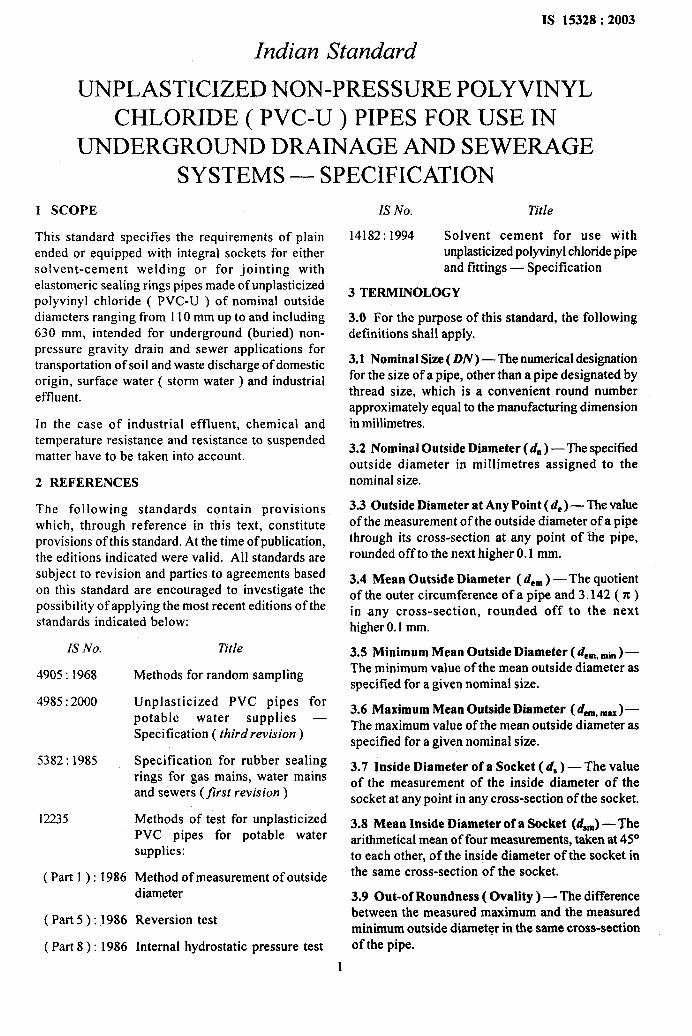
D-1 SCOPE
This Annex specifies a method of testing theIeaktightness under positive pressure ofassemblies of polyvinyl chloride ( PVC-U ) pipeswith elastomeric sealing ring type socket jointsincluding the following:
a) Single sockets of pipes;
b) Double sockets; and
c) Sockets of figings.
It also applies to elastomeric sealing ring typesockets made of ductile iron for use with PVC-Upressure piping.
D-2 PRINCIPLE
A joint assembly as a test specimen consisting of aPVC-U pipe mounted into a PVC-U socket is exposed,within a specified temperature range, to a specifiedinternal pressure regime for a specified time while thepipe is subject to an angular deflection in the socket.While under pressure the test piece is monitoredfor signs of leakage.
NOTE — It is assumed that the following test parametersare set by the standard making the reference to thisstandard:
a) Test pressure, and
b) Number of test specimens to be used.
D-3 APPARATUS
D-3. 1 Framework — Comprising of at least twofixing devices, one of which is movable to allowangular deflection, vertical or horizontal, to be applied
within the socket. A typical arrangement is shownin Fig. 11.
D-3.2 A pressure contro) device connected tothe test specimen and capable of applying andmaintaining a variable internal hydrostatic pressureof the PVC-U pipe section mounted into the socketof the component to be tested.
D-3.3 The assembly shall be carried out in accordancewith the socket manufacturer’s instructions.
D-3.4 A pipe of the same nominal pressure as that ofthe socket shall be used for the te$t.
D-3.5 The length of the pipe section shall be suchthat the free length, L, between the socket and theend-seal is equal to five times the normal outsidediameter, d,, of the pipe with a minimum of 500 mmand a maximum of 1500 mm.
NOTE — The mean outside diameter, dem, of thepipe should preferably conform to the minimum specifiedvalue, and the socket dimensions ( mean inside diameter,dim,and the diameter of the groove for housing the sealingring ) should preferably conform to the maximum valuesstated by the manufacturer, in order to have dimensionsas close to the extreme Iimits of the relevant tolerances.
D-4 PROCEDURE
D-4. 1 Secure the socket, without any deformation,to the solid framework and align the pipe section withthe axis of the socket.
D-4.2 Incline the pipe in the test apparatus, determinethe free angle of deflection, u, which the joint cantolerate without application of force.
Ifct22°, firmlyanchor the pipe to maintain the deflectedpipe in this position for the remainder of the test.
17
IS 15328:2003
>lOmmL= 5dn (min. 500mm ANO mox.1500 mm-)
.—. —.-—-— .-
[
FIG. 11 TYPICALARRANGEMENTOFFRAMEWORK
If ct <2°, carry out the test at a deflection of 2° byforcing the pipe to that degree of deflection.
D-4.3 Measure the mean outside diameter at a point0.5 d. away from the mouth of the socket. Calculatethe amount of distortion required and tighten the boltsof the distortion clamp until the required distortionis achieved.
D-4.4 Fill the test specimen with water at a temperatureof 27 + 5°C and release any trapped air.
D-4.5 Condition the test specimen assembly for aperiod of at least 20 min to ensure equalization oftemperature.
D-4.6 While testing in accordance with 5.7:
a)
b)
Maintain the ambient temperaturewithin &5°C of any temperature between 20and 32”C; and
Examine the joint during the whole test cycleand record any sign of leakage.
D-4.7 Apply and raise the hydrostatic pressureslowly over a period of not less than 15 min to aminimumof0.05MPa (0.5 bar). Maintainthepressmatthis value for a minimum of 15 min.
D-5 TEST REPORT
The test report shall include the followinginformation.
a)
b)
c)
d)
e)
Nominal pressure class of the PVC-U pipeand socket used for the test;
Angle of deflection, et, used for the test;
Ambient temperature during the test;
Information of the leaktightness of the joint
Any factors which may have tiected theresults, such as, any incidents or any operatingdetails not specified in this standard; and
t) Date of the test.
ANNEX E
( Clause 10.1.2)
TEST METHOD FOR LEAKTIGHTNESS OF ELASTOMERIC SEALING RING TYPE SOCKETJOINTS UNDER NEGATIVE INTERNAL PRESSURE AND WITH ANGULAR DEFLECTION
E-1 SCOPE
This Annex specifies a method of testing theleaktightness under negative pressure of assemblies
of polyvinyl chloride ( PVC-U ) pipes with elastomericsealing ring type socket joints including:
a) Single sockets of pipes;
b) Double sockets; and
c) Sockets of fittings.
It also applies to elastomeric sealing ring typesockets made of ductile iron for use with PVC-Upressure piping.
E-2 PRINCIPLE
A joint assembly as a test specimen consisting of aPVC-U pipe mounted into a PVC-U socket is exposed,within a specified temperature range, to a specifiednegative pressure for a specified time while the pipe
18
IS 15328:2003
is subject to an angular deflection in the socket. While
under vacuum the test ,piece is monitored for signsof leakage.
NOTE — It is assumed that the following test parametersare set by the standard making the reference to thisstandard:
a) Test pressure, and
b) Number of test specimens to be used.
E-3 APPARATUS
E-3.1 Framework — Comprisingof atleasttwofixingdevices, one of which is movable to allow angulardeflection, vertical or horizontal, to be appliedwithin the socket. A typical arrangement is shownin Fig. 12.
E3.2 Vacuum Pump and Control Device-Connectedto the test specimen, preferably at the immovable endof the apparatus, and capable of applying andmaintaining two required levels of negative pressureof the PVC-U pipe section mounted into the socketof the component to be tested.
E-3.3 An isolation valve between the test piece andthe vacuum pump.
E-3.4 The assembly shall be carried out in accordancewith the socket manufacturer’s instructions.
E-3.5 A pipe of the same nominal pressure as that ofthe socket shall be used for the test.
E-3.6 The length of the pipe section shall be suchthat the free length, L, between the socket and theend-seal is equal to five times the normal outsidediameter, d., of the pipe with a minimum of 500 mmand a maximum of 1500 mm.
NOTE— The mean outside diameter, dm, of the pipeshould preferably conform to the minimum specifiedvalue, and the socket dimensions ( mean inside diameter,
dm, and the diameter of the groove for housing the sealingring ) should preferably conform to the maximum valuesstated by the manufacturer, in order to have dimensionsas close to the extreme limits of the relevant tolerances.
E-4 PROCEDURE
E-4. 1 Secure the socket, without any deformation,to the immovable portion of the framework and alignthe pipe section with the axis of the socket.
E-4.2 Incline the pipe in the test apparatus,determinethe free angle of deflection, cz,which the joint cantolerate without application of force.
Ifct> 2°, firmly anchorthepipeto maintainthe deflectedpipe in this position for the remainder of the test.
If rx <2°, carry out the test at a deflection of 2° byforcing the pipe to that degree of deflection.
E-4.3 Measure the mean outside diameter at a point0.5 d. away from the mouth of the socket. Calculatethe amountof distortionrequiredandtighten the boltsof the distortion clamp until the required distortionis achieved.
E-4.4 While testing, maintain the ambienttemperaturewithin * 5°C of anytemperaturebetween20 and 32°C.
E-4.5 Apply a negative pressure ( vacuum )the test piece until a constant gauge pressure-0.03 Mpa ( -0.3 bar) is achieved.
toof
E-4.6 Isolate the vacuum pump fr~rnthe test piece,but not from the control device. Record the changein the negativepressurefor 15 min. During this period,the variation in negative pressure should not be morethan * 10 percent of the required test pressure.
E-4.7 Again, isolate the vacuum pump from the testpiece, monitor the pressure for a fhrther 15 min andrecord any“changein the negative pressure.
>lOmmL= 5dn (min. 500mm AND mox.1500 mm)
.—. —- — . —=% —. 4’-—-— - —-
[
FIG. 12 TYPICALARRANGEMENTOFFRAMEWORK
19
IS 15328:2003
E-5 TEST REPORT c) Ambient temperature during the test;
The tesi report shall include the following information: d) Information of the Ieaktightness of the joint;
e) Any factors which may have affected thea) Nominal pressure class of the PVC-U pipe results, such as, any incidents or any operating
and socket used for the test; details not specified in this standard; and
b) Angle of deflection, et, used for the test; ~ Date of the test.
ANNEX F
( Clause11 )
SAMPLING AND CRITERIA FOR CONFORMITY
F-1 ACCEPTANCE TESTS
F-1. 1 Acceptance tests are carried out on samplesselected from a lot for the purpose of acceptance ofthe lot.
F-1.2 All PVC pipes in a single consignment of thesame class, same size and manufactured underessentially similar conditions shall constitute a lot.
F-1.3 For ascertaining the conformity of the’ lot tothe requirements of the standard, samples shall betested from each lot separately.
F-1.4 Visual and Dimensional Requirements
F-1 .4.1 The number of test samples taken from a lotshall depend on the size of the lot and the outsidediameter of the pipes, and shall be in accordance withTable 13.
F-1 .4.2 These pipes shall be selected at randomfrom the lot and in order to ensure the randomnessof the selection, a random number table shall be used.For guidance, and use of random number tables,IS 4905 may be referred to. In the absence of arandom number table, the following procedure maybe adopted:
Starting from any pipe in the lot, count 1, 2, 3 . . .and so on up to r, where r is the integral part ofN/n, N being the number of pipes in the lot, and n thenumber of pipes in the sample. Every rth pipe socounted shall be withdrawn so as to constitute therequired sample size.
F-1.4.3 The number of pipes given for the first samplein CO14 of Table 13, shall be taken from the lot andexamined for visual and dimensional requirements givenin 6, 7.1 and 7.2. A pipe failing to satisfy any of theserequirements shall be considered defective. The lotshall be deemed to have satisfied these requirements,if the number ofdefectives found in the first sampleis less than or equal to the corresponding acceptancenumber given in COI6 of Table 13. The lot shall be
deemed not to have met these requirements, if thenumber of defective found in the first sample is greaterthan or equal to the corresponding rejection numbergiven in COI7 of Table 13. If, however, the number ofdefective found in the first sample lies between thecorresponding acceptance or rejection numbers givenin CO16 and 7, a second sample of the size given inCO14 shall be taken and examined for theserequirements. The lot shall be considered to havesatisfied these requirements if the cumulative sampleis less than or equal to the corresponding acceptancenumber given in CO16, otherwise not.
F-1.5 Reversion Test
F-1.5.1 The lot, having satisfied visual and dimensionalrequirements, shall be tested for reversion.
F-1.5.2 For this purpose, the number of pipes givenfor the first sample in COI3 of Table 14 shall be takenfrom the lot. The sample pipe failing in reversion shallbe considered to be defective. The lot shall be deemedto have met the requirements given in this standardfor the reversion test if the number of defective foundin the first sample is less than or equal to thecorresponding acceptance number given inCO15. Thelot shall be deemed not to have met the requirements,if the number of defective found in the first sampleis greater than or equal to the corresponding rejectionnumber given in COI6. If, however, the number ofdefective in the first sample lies between thecorresponding acceptance and rejection numbers givenin co] 5 and 7, a second sample of the size given inCOI3 shall be taken and examined for the requirement.The lot shall be deemed to have satisfied therequirements, if the number of defective found in thecumulative sample is less than or equal to thecorresponding acceptance number given in COI6,otherwise not.
F-1.6 Vicat Softening Temperature
F-1.6.1 The lot, having satisfied the visual and
20
IS 15328:2003
Table 13 Scale of Sampling for Vkual Appearance and Dimensional Requirements
( Clauses F-1.4.1 arrdF-l .4.3 )
S1 No. Number of Pipes Samplein the Lot Number
(1) (2) (3)
i) up to 1000 First
Second
ii) 1001 to 3000 First
Second
iii) 3001 to 10000 First
Secondiv) 10001 and above First
Second
SampleSize
(4)
13
13
20
20
32
32
50
50
CumulativeSample Size
(5)
13
26
20
40
32
64
50
100
AcceptanceNumber
(6)o
1
0
1
0
3
1
4
RejectionNumber
(7)
2
2
2
2
3
4
4
5
Table 14 Scale of Sampling for Reversion and Vicat Softening Temperature Tests
( Clauses F-1.5.2 andF-l .6.2 )
Number of Pipes Sample Sample Cumulative Acceptance Rejectionin the Lot Number Size Sample Size Number Number
(1) (2) (3) (4) (5) (6)
For nominal diameters up to and including 110 mm
up to 1000 First 5 5 0 2
Second 5 10 1 2
1001 to 3000 First 8 8 0 2
Second 8 16 1 2
3001 to 10000 First 13 13 0 2
Second 13 26 1 2
1000 I and above First 20 20 0 3
Second 20 40 3 4
For nominal diameters above 110 mm
up to 3000 First 3 3 0 2
Second 3 6 1 2
3001 to 10000 First 5 5 0 2
Second 5 10 1 2
10000 and above First 8 8 0 2
Second 8 16 1 2
dimensional requirements, shall be tested for Vicatsoftening temperature.
F-1 .6.2 For this purpose, the procedure adopted forsampling and criteria for conformity shall be the sameas given in F-1.5, using Table 14.
F-1.7 Resistance to External Blows at O“C
F-1 .7.1 The lot, having been found satisfactoryaccording to F-1.4, F-1.5 and F-1.6, shall be testedfor resistance to external blows at O“C.
F-1 .7.2 For this purpose, the procedure adoptedfor sampling and criteria for conformity shall be asspecified in Table 15.
21
F-2 TYPE TESTS
F-2.1 Type tests are intended to prove the suitabilityand performance of a new corpposition or a new sizeof pipe, Such tests, therefore, need to be applied onlywhen a change is made in polymer composition orwhen a new size is to be introduced.
F-2.1. 1 Resistance to Internal Hydrostatic Preksure( ~pe Test )
F-2.1.1.1 For this test, the manufacturer or thesupplier shall supply furnish to the testing authority,three samples of pipes of different diameters anddifferent classes, selected preferably from a reguIarproduction lot.
IS 15328:2003
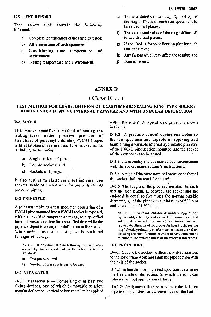
Table 15 Scale of Sampling for Resistance to External Blows
(Clause F-1 .7.2)
Number of Pipes Sample Sample Cumulative Acceptance Rejectionin tbe Lot Number Size Sample Size Number Number
(1) (2) (3) (4) (5) (6)
For all sizes
up to 3000 First 3 3 0 2
Second 3 6 1 2
3001 to 10000 First 5 5 0 2
Second s 10 1 2
10001 and above First 8 8 0 2
Second 8 16 I 2
NOTE — The numbers mentioned in CO13 to 6 in the table represent the number of times the test is to be carried outand do not represent either the number of pipe samples or the number of blows or the number of failures.
P-2.1.1.2 Three samples so selected shall be testedfor compliance with the requirements of the type testgiven in Table 6.
F-2.1 .1.3 If all the three samples pass therequirements of the quality test, the type of pipeunder consideration shall be considered to be eligiblefor type approval, which shall be normally valid for a
period of one year.
F-2.1.1.4 In case any of the samples fail in this test,
the testing authority, at its discretion, may call for fresh
samples not exceeding the original number and subjectthem to the type test. If, in the repeat test, no singlefailure occurs, type of pipe shall be considered fortype approval. If any of the samples fails in the repeattests, the type of pipe shall not be approved. Themanufacturer or the supplier maybe asked to improvethe design and resubmit the product for type approval.
F-2.1.1.5 At the end of the validity period (normallyone year) or earlier, if necessary, the testing authoritymay call for fresh samples for ~pe test for the purposeof type approval.
22
IS 15328:2003
ANNEX G
( I’orewor~ )
COMMITTEE COMPOSITION
Plastic Piping System Sectional Committee, CED 50
Organization
Engineer-in-Chief’s Branch, Army Headquarters, New Delhi
Ahmedabad Municipal Corporation, Ahmedabad
Brihanmumbai Mahanagar Palika, Mumbai
Building Materials and Technology Promotion Council,New Delhi
Calcutta Municipal Corporation, Kolkata
Carbon Everflow Limited, Nashik
Central Building Research Institute, Roorkee
Central Institute of Plastic Engineering Technology,Bhopal/Lucknow
Central Public Health Environment Engineering Organization,New Delhi
Central Public Works Department, New Delhi
Chennai Metropolitan Water Supply and Sewerage Board,Chennai
Delhi Development Authority, New Delhi
Delhi Jal Board, New Delhi
Department of Telecommunications, New Delhi
Directorate General of Supplies and Disposals, Mumbai /Patna
Engineer-in-Chief’s Branch, Army Headquarters, New Delhi
EPC Industries Private Limited, Nashik
Fioolex Industries Limited, Pune
Housing and Urban Development Corporation Limited,New Delhi
National Environmental Engineering Research Institute,Nagpur
NOCIL Limited, Thane
Public Health Engineering, Bhubaneswar
Public Health Engineering, Roorkee
Public Health Engineering Department, Jaipur
Public Health Engineering Department, Bangalore
Reliance Industries Limited, Mumbai
RITES, New Delhi
Supreme Industries Limited, Jalgaon
Tamil Nadu Water Supply and Drainage Board, Chennai
U.P. Jal Nigam, Lucknow
Uniplas India Limited, New Delhi
Vinplex India Private Limited, Chennai
In personal capacity (C-478B, Sushanl Lok, Phase 1,Gurgaon )
In personal capacity ( 196 Gulmohar Park, New Delhi 110049)
BIS Directorate General
Representative(s) t
DEPUTY CHIEF ENGINEER(MTRL MGT UNIT)
SHRI S. SUNDRAiV
SHRI P. V.KULKARNI ( Alternate )
SHRI S. B. LAL
SHRI A. K. NAGAR ( Alternate )
DR M. V. NANOTI
DR S. P. PANDE ( Alternate )
SHRI R. K. BHATIA
SHRI A. R. PARASURAMAN( Alternate )
SHRI P. C. MAHAPATRA-
SHRI G. C. PATRA( Alternate )
SHRI SUDESHKUMAR SHARMA
SUPERINTENDINGENGINEER
EXECUTIVE ENGINHEER( Alternate )
SHRI GULAM AHMED
SHRI SUBHASHSANZGIRI
SHRI V. B. RAMARAO( Alternate )
Member Secretaries
SHRI J. K. PRASAD
Director (CED), BIS
SHRI C. K. SHARMA
SHRI G. K. SAXENA
SHRI WILLIAM HANDONES ( Alternate )
JOINT CHIEF ENGINEER( CONTRACT )
ENGINEERINGDIRECTOR ( Alternate )
MATERIALS MANAGER
CHIEF ENGINEER( PPR & D ) ( Alternate )
MANAGING DIRECTOR
SHRI G. K. SRINIVASAN
SHRI P. SAI VENKATA PRASAD ( Alternate )
SHRI O. P. RATRA
SHRI KANWAR A. SINGH
SHRI S. K. JAIN, Director and Head (CED)[.Representing Director General ( Ex-ofJcio ) ]
SHRI R. K. GUPTA
Joint Director (CED), BIS
( Continued on page 25)
24
( Continued from page 24)
IS 15328:2003
PVC and ABS Piping System Subcommittee,
Organization
Vinplex India Pvt Limited, Chennai
All India PVC Pipe Manufacturers Association, New Delhi
Ashirvad Enterprises, Patna
Brihanmumbai Mahanagar Palika, Mumbai
Central Institute of Plastic Engineering and Technology,Bhopal
Central Public Works Department, New Delhi
Delhi Jal Board, New Delhi
Delhi Test House, New Delhi
Department of Telecommunications, New Delhi
Directorate General of Supplies and Disposals,
Kolkata/New Delhi
Finolex Industries Limited, Pune
Jain Irrigation Systems Limited, Jalgaon
Mahanagar Telephone Nigam Limited, New Delhi
National Organic Chemical Industries Limited, Thane
Reliance Industries Limited, Mumbai
Rex Poiyextrusion Limited, Sangali
RITES, New Delhi
Supreme Industries, Jalgaon
Tamil Nadu Water Supply and Drainage Board, Chennai
Tamil Nadu Water Supply and Sewage Board, Chennai
Telecommunications Consultants India Limited, New Delhi
In personal capacity ( C-478B, Sushant Lok, Phase 1, Gurgaon )
In personal capacity ( /96 Grdmohar Park, New Delhi 110049)
25
CED 50:3
Representative(s)
SHRI G. K. SRINIVASAN( Convener)SHRI P. SAIVANKATAPRASAD ( Alternate )
SHRI S. S. GUPTA
SHRI DEEPAK PODDAR
SHRI L. N. PODDAR ( Alternate )
HYDRAULIC ENGINEER
DEPUTY HYDRAULIC ENGINEER( Ahernate )
DR VIIAIKUMAR
DR SONIA AICUTAR( Alternate )
CHIEF ENGINEER( CSQ )
EXECUTIVEENGINEER( S & S ) ( Alternate )
ENGINEER-IN-CHIEF (W)SHRI S. K. CHADHA ( Alternate )
SHRI M. C. GOEL
SHRI V. L. VENKATARAMAN
SHRI P. ADINARAYANA( Alternate )
SHRI RAIENDER PRASAD
SHRI N. K. KAUSHAL ( Alternate )
DR DHANANIAY RAU
SHRI V. V. KANDEKAR ( Alternate )
SHRI S. NARAYANASWAMI
SHRI L. JAGANNATHAN( Alternate )
SHRI S. K. CHADHA
SHRI M. K. SINGHAL ( Alternate )
SHRIP. K. BHATIASHRIM. M. SHAH ( Alternate )
DR S. M. DIWAN
SHRI M. V. PRASAD ( Alternate )
SHRI CHANDERSEKHAR
SHRI C. K, SHAR~A
DEPUTY CHIEF INSPECTORENGINEER
( Alternate)
SHRI W. MANDONCA
SHRI G. K. SAXENA ( Alternate )
ENGINEER-IN-CHIEF
JOINT CHIEF ENGINEER( MATERIAL )
( Alternate)
SHRI P. M. HARINATH
DEPUTY DIRECTOR (CR) ( Alternate )
SHRIS. N. JHASHRIM. K. SRIVASTAVA( Alternate )
SHRI O. P. RATRA
SHRI KANWAR A. SINGH
Bureau of Indian Standards
BIS is a statutory institution established under the Bureau of Indian Standards Act, 1986 to promoteharmonious development of the activities of standardization, marking and quality certification of goods andattending to connected matters in the country.
Copyright
131Shas the copyright of all its publications. No part of these publications maybe reproduced inany form withoutthe prior permission in writing of BIS. This does not preclude the free use, in the course of implementing thestandard, of necessary details, such as symbols and sizes, type or grade designations. Enquiries relating tocopyright be addressed to the Director (Publications), BIS.
Review of Indian Standards
Amendments are issued to standards as the need arises on the basis of comments. Standards are also reviewedperiodically; a standard along with amendments is reaffirmed when such review indicates that no changes areneeded; if the review indicates that changes are needed, it is taken up for revision. Users of Indian Standardsshould ascertain that they are in possession of the latest amendments or edition by referring to the latest issueof ‘BIS Catalogue’ and ‘Standards : Monthly Additions’.
This Indian Standard has been developed from Doc : No. CED50(5931 ).
Amendments Issued Since Publication
Amend No. Date of Issue Text Affected
BUREAU OF INDIAN STANDARDS
Headquarters:
Manak Bhavan, 9 Bahadur Shah Zafar Marg, New Delhi 110002 Telegrams: ManaksansthaTelephones: 23230131,23233375,2323 9402 ( Common to all offices)
Regional Offices: Telephone
Central: Manak Bhavan, 9 Bahadur Shah Zafar Marg
{23237617
NEW DELHI 110002 23233841
Eastern: 1/1 4 C. I. T. Scheme VIl M, V, 1. P. Road, Kankurgachi