This publication is protected under the Indian Copyright Act (XIV of 1957) andreproduction in whole or in part by any means except with written permission of thepublisher shall be deemed to be an infringement of copyright under the said Act.
Indian StandardCODE OF PRACTICE FOR
DESIGN AND CONSTRUCTION OFMACHINE FOUNDATIONS
PART I FOUNDATION FOR RECIPROCATINGTYPE MACHINES
( Second Revision )Foundation Engineering Sectional Committee, BDC 43Chairman Representing
PROF DINESH MOHAN Central Building Research Institute (CSIR),Roorkee
Members
DR R. K. BHANDARI Central Building Research Institute (CSIR),Roorkee
SHRI DEVENDRA SHARMA ( Alternate )CHIEF ENGINEER
SHRI S. GUHA ( Alternate )Calcutta Port Trust, Calcutta
SHRI M. G. DANDAVATESHRI N. C. DUGGAL ( Alternate )
The Concrete Association of India, Bombay
SHRI A. G. DASTIDAR In personal capacity ( 5 Hungerford Court, 121,Hungerford Street, Calcutta )
SHRI V. C. DESHPANDE The Pressure Piling Co (I) Pvt Ltd, BombaySHRI A. GHOSAL Stup Consultants Limited, BombayDIRECTOR (CSMRS) Central Soil & Material Research Station, New
DelhiDY DIRECTOR (CSMRS) ( Alternate )
SHRI A. H. DIVANJI Asia Foundations and Construction Pvt Ltd,Bombay
SHRI A. N. JANGLE ( Alternate )SHRI R. K. DAS GUPTA
CalcuttaDR JAGDISH NARAIN Indian Geotechnical Society, New Delhi
PROF SWAMI SARAN ( Alternate )SHRI G. S. JAIN G. S. Jain & Associates, Roorkee
SHRI ASHOK KUMAR JAIN ( Alternate )SHRI N. JAGANNATH Steel Authority of India, Bokaro
SHRI A. K. MITRA ( Alternate )
( Continued on page 2 )
IS : 2974 (Part I) - 1982
2
( Continued from page 1 )
Members Representing
JOINT DIRECTOR (DESIGNS) National Buildings Organisation, New DelhiSHRI SUNIL BERY ( Alternate )
JOINT DIRECTOR RESEARCH(GE)-I, RDSO
Ministry of Railways
JOINT DIRECTOR RESEARCH (B & S), RDSO ( Alternate )
DR R. K. KATTI Indian Institute of Technology, BombaySHRI S. R. KULKARNI
SHRI S. ROY ( Alternate )M. N. Dastur & Co Pvt Ltd, Calcutta
SHRI O. P. MALHOTRA Public Works Department, ChandigarhAdministration
SHRI A. P. MATHUR Central Warehousing Corporation, New DelhiSHRI V. B. MATHUR Machenzies Limited, BombaySHRI T. K. D. MUNSI Engineers India Limited, New Delhi
SHRI M. IYENGAR ( Alternate )SHRI B. K. PANTHAKY
SHRI V. M. MADGE ( Alternate )The Hindustan Construction Co Ltd, Bombay
SHRI M. R. PUNJASHRI S. MUKHERJEE ( Alternate )
Cemindia Co Ltd, Bombay
SHRI N. E. V. RAGHVAN The Braithwaite Burn & Jessop ConstructionCompany Limited, Calcutta
PROF GOPAL RANJAN University of Roorkee, RoorkeeDR V. V. S. RAO Nagadi Consultants Private Ltd, New DelhiSHRI T. N. SUBBA RAO
SHRI S. A. REDDY ( Alternate )Gammon India Limited, Bombay
SHRI ARJUN RIJHSINGHANI Cement Corporation of India, New DelhiSHRI O. S. SRIVASTAVA ( Alternate )
DR A. SARGUNAN College of Engineering, GuindySHRI S. BOMMINATHAN ( Alternate )
SHRI K. R. SAXENA Engineering Research Laboratories, Governmentof Andhra Pradesh, Hyderabad
BRIG OMBIR SINGH Engineer-in-Chief’s Branch, Army Headquarters,New Delhi
LT-COL K. P. ANAND ( Alternate )SHRI N. SIVAGURU
SHRI K. P. SARKAR ( Alternate )Ministry of Shipping and Transport, New Delhi
SUPERINTENDING E N G I N E E R(DESIGNS)
EXECUTIVE ENGINEER(DESIGNS) V ( Alternate )
Central Public Works Department, New Delhi
SHRI M. D. TAMBEKAR Bombay Port Trust, BombayDR A. VARADARAJAN Indian Institute of Technology, New Delhi
DR R. KANIRAJ ( Alternate )SHRI G. RAMAN, Director General, ISI ( Ex-officio Member )
Director (Civ Engg)
SecretarySHRI K. M. MATHUR
Deputy Director (Civ Engg), ISI
( Continued on page 22 )
IS : 2974 (Part I) - 1982
3
Indian StandardCODE OF PRACTICE FOR
DESIGN AND CONSTRUCTION OFMACHINE FOUNDATIONS
PART I FOUNDATION FOR RECIPROCATINGTYPE MACHINES
( Second Revision )0. F O R E W O R D
0.1 This Indian Standard (Part I) (Second Revision) was adopted bythe Indian Standards Institution on 26 July 1982, after the draftfinalized by the Foundation Engineering Sectional Committee hadbeen approved by the Civil Engineering Division Council.0.2 Installation of heavy machinery has assumed increasedimportance in the wake of the vast programme of industrialdevelopment in the country. Foundations for these machines have tobe specially designed taking into consideration the impact andvibration characteristics of the load and the properties of soil underdynamic conditions. While many of the special features relating to thedesign and construction of such machines foundations will have to beas advised by the manufacturers of these machines, still a large part ofthe details will have to be according to certain general principles ofdesign covering machine foundations. This standard is intended to laydown these general principles. This part, which is the first of a seriesof standards relating to machine foundations, deals with machines ofthe reciprocating type for which rigid-block type foundations aregenerally used. This standard was first published in 1964 and revisedin 1969. In this revision, the principal modifications made are inrespect to providing additional information of pile foundation, groutingand inclusion of guidelines for installation of anti-vibration mountingsand testing and measurement of vibration.0.3 This edition 3.1 incorporates Amendment No. 1 (November 1985).Side bar indicates modification of the text as the result ofincorporation of the amendment.0.4 For the purpose of deciding whether a particular requirement ofthis standard is complied with, the final value, observed or calculated,expressing the result of a test or analysis, shall be rounded off inaccordance with IS : 2-1960*. The number of significant placesretained in the rounded off value should be the same as that of thespecified value in this standard.
*Rules for rounding off numerical values ( revised ).
IS : 2974 (Part I) - 1982
4
1. SCOPE
1.1 This standard covers the design and construction of foundations formachines of the reciprocating type which normally generate steadystate vibration and is of a size for which a rigid block type foundationis normally used.
2. TERMINOLOGY
2.0 For the purpose of this standard, the definitions of the followingterm shall apply ( see Fig. 1 ).
FIG. 1 AXES AND CO-ORDINATES
IS : 2974 (Part I) - 1982
5
2.1 Supporting Ground — That part of the ground carrying loadarising from the machine and foundation.2.2 Foundation — The part of the structure in direct contact with,and transmitting loads to the supporting ground.2.3 Forces and Couples
2.3.1 External Forces — The unbalanced part of the periodic inertiaforces caused by the acceleration and deceleration of reciprocatingparts. The primary inertia force has one complete cycle and thesecondary inertia force two cycles per revolution of the crank shaft.2.3.2 Vertical Force — An unbalanced force at machine operationfrequency or twice the operation frequency, or both, acting in thedirections of axis Z.
2.3.3 Horizontal Force — An unbalanced force at machine operationfrequency or twice machine operation frequency, or both acting in thedirections of axis X.2.3.4 External Couple — A moment which occurs when one inertiaforce is balanced by another but in a separate line of action. Forfoundation design it is usually necessary to consider only the primaryand secondary vertical and horizontal couples.2.3.5 Vertical Couple — An unbalanced couple at machine operationfrequency or twice the machine operation frequency, or both acting inthe planes of axes Z.2.3.6 Horizontal Couple — An unbalanced couple at machine operationfrequency or twice the machine operation frequency, or both, acting inthe planes of axes X .2.4 Torque
2.4.1 Harmonic Torque Reaction — Turning moment in plane of axesXZ, the frequencies of which depend on number of cylinders andconfiguration of the machine.2.5 Periodic Motion — The motion which repeats itself in all itsparticulars at regular intervals of time is called the periodic motion.2.5.1 Aperiodic Motion — The motion which does not repeat itself atregular intervals of time is called aperiodic motion.2.6 Damping — Damping is associated with energy dissipation and isthe internal resistance offered by a foundation system to the vibrationof machine. It is termed viscous damping when the force of damping isdirectly proportional to the instantaneous velocity of the oscillatingsystem.
IS : 2974 (Part I) - 1982
6
2.6.1 Damping Constant ( C ) — Constant of proportionality relatingforce of damping with instantaneous velocity of motion.
2.6.2 Critical Damping ( Cc ) — The magnitude of damping at whichthe motion of the system changes from periodic to aperiodic.
where Cc = for single degree of freedom system
2.6.3 Damping Factor — The ratio of the damping constant ( C ) to thecritical damping ( Cc ) of the system.
2.7 Amplitude of Motion — The distance that a body moves from itsposition of rest when subjected to vibration.
2.8 Frequency — The number of times a periodic motion repeatsitself expressed in revolutions or cycles per minute ( f ).
2.8.1 Operation Frequency — The rotating speed of the main drive incycles per second or the frequency of the periodic force acting on thesystem.
NOTE — System means the machine, the foundation block and soil.
2.8.2 Angular Frequency ( ) — The frequency expressed in radiansper second.
2.8.3 Natural Frequency ( fn ) — The frequency of free vibration of abody.
2.8.4 Disturbing Frequency — The frequency of a periodic force.
2.8.5 Limiting Frequencies — If a system possesses ‘n’ degrees offreedom having ‘n’ natural frequencies f1, f2, f3, f4, ............. fn, theminimum and maximum of such frequencies, fmin and fmax are knownas limiting frequencies of the system.
2.8.6 Frequency Ratio ( f/fn ) — The ratio of the operating frequency tothe natural frequency.
2.9 Degrees of Freedom of a System — The degree of freedom of asystem is defined as the number of coordinates required to describe thedisplaced position of the system ( see Fig. 2 ).
2.10 Reasonance — When the frequency of the forced vibration(operating frequency of the machine) equals the natural frequency ofthe foundation soil system the condition of resonance is reached.
2.11 Mass Moments of Inertia — The resistance of a mass torotation and equal to its mass times the radius of gyration squared.
mk2
IS : 2974 (Part I) - 1982
7
2.12 Mass-Spring System2.12.1 Single Mass Spring System — A rigid body supported by anumber of springs, such a system has six natural frequencies, three ofthem being translational or three cartesian, co-ordinate axes and theother three being rotational on three planes in a cartesian co-ordinatesystem.2.12.2 Multiple Mass-Spring System — A number of rigid bodiesconnected by a series of relatively flexible springs. The naturalfrequencies depend on the number of degrees of freedom being definedas the number of co-ordinates required to identify a point on the rigidbody.2.13 Fatigue Factor or Fatigue Coefficient — The factor of safetyutilized to obtain equivalent static force for a dynamic force so as totake care of reduction in the strength of the concrete and steel due torepeated loading. The factor should be assumed as 3 unless otherwisespecified.
FIG. 2 SYSTEM OF AXES AND THE SIX DEGREES OF FREEDOM
IS : 2974 (Part I) - 1982
8
3. NOTATIONS
3.1 The notations given in Appendix A shall apply.
4. NECESSARY DATA
4.1 Data to be Provided by Machine Manufacturer — Themanufacturer should provide information as outlined in 4.1.1 to 4.1.3.
4.1.1 Generala) Description of driving and driven machinery,b) Operating speed or speed ranges,c) Number and arrangement of cylinders,d) Distance between axis of main shaft of the machine and the top
face of foundation,e) Maximum rated output,f) Gear box ratio where applicable, andg) Maximum operating temperature in the bases of the machine.
4.1.2 For Static Design
4.1.2.1 A detailed loading diagram comprising plan, elevation andsection showing details of communication and point of all loads onfoundation.
4.1.2.2 A detailed drawing showing the position and size of mountingfeet and details of holding down bolts.
4.1.3 For Dynamic Design
4.1.3.1 Details of out of balance forces and couples shall be given,together with associated frequencies for all possible modes of vibrationfor driving and driven machinery. These include the following:
4.1.3.2 Mass moments of inertia of driving and driven machine aboutthree principal axes shall be indicated.
4.1.3.3 Additional information relating to specific machines, as givenbelow, shall be provided where necessary:
a) Loads due to dynamic short circuit conditions, andb) Loads due to an abnormal sudden stoppage.
IS : 2974 (Part I) - 1982
9
4.1.3.4 Where it is found necessary to use anti-vibration mountings,the type and positions be indicated.
4.2 Data on Ground and Site Conditions — The following soil datashall be known:
a) Soil profile and soil characteristics up to a depth at least threetimes the expected mean plan dimension of the foundation whichcan be taken as the square root of the expected area, or hardstrata.
b) Soil investigation to the extent necessary in accordance withIS : 1892-1979* and for the determination of dynamic propertiesof soil in accordance with IS : 5249-1977†.
c) The relative position of the water table below ground at differenttimes of the year.
5. DESIGN CRITERIA
5.1 General
5.1.1 The foundation structure of machine shall be isolated at all levelsfrom the main building and from other foundations as far as possible.
5.1.2 Overhanging cantilevers where unavoidable shall be designed toensure rigidity against vibration.
5.1.3 All machine foundations shall satisfy two fundamental criteria;that resonance does not occur between the frequencies of the pulsatingloads and natural frequency of foundation/soil system and also theamplitude of vibration does not exceed safe limits. Design criteriabased on frequency and amplitude limits can be classed as follows:
a) Limits set by the possibility of damage or uneconomic wear tomachinery or associated equipment or both,
b) Limits set by the possibility of damage to building structures,
c) Limits of structural borne vibrations to ensure confort of person,and
d) Limits set by possibility of disturbance of ground resulting inunacceptable settlement of foundation.
*Code of practice for subsurface investigation for foundations ( first revision ).†Method of test for determination of dynamic properties of soil ( first revision ).
IS : 2974 (Part I) - 1982
10
5.2 Frequency Ratio — Wherever possible the natural frequency ofthe foundation soil-system shall be higher than the highest disturbingfrequency and the frequency ratios shall not be normally less than 0.4.Where this is not possible, the natural frequency of the foundation-soilsystem shall be kept lower than the lowest disturbing frequency. Thefrequency ratios in such cases shall not be lower than 1.50. While theabove criteria shall be applied to all possible modes of vibration, it maybe permitted to operate machines closer to the resonance in certainmodes of vibration provided the resulting amplitudes do not exceed thepermissible limit.
NOTE — Even though machine may be balanced, minor disturbing forces can occurdue to manufacturing tolerances and other causes, for sensitive installations, thefrequencies arising from these may have to be considered.
5.3 Permissible Amplitudes
5.3.1 Limitations of Vibration Amplitude to Avoid Damage toMachinery — This shall be specified by the manufacturer and shall inno cases be exceeded. Where no specific limit has been stated by themanufacturer, it may be taken that foundation satisfying the followingamplitude criteria shall provide a satisfactory base for machinery.
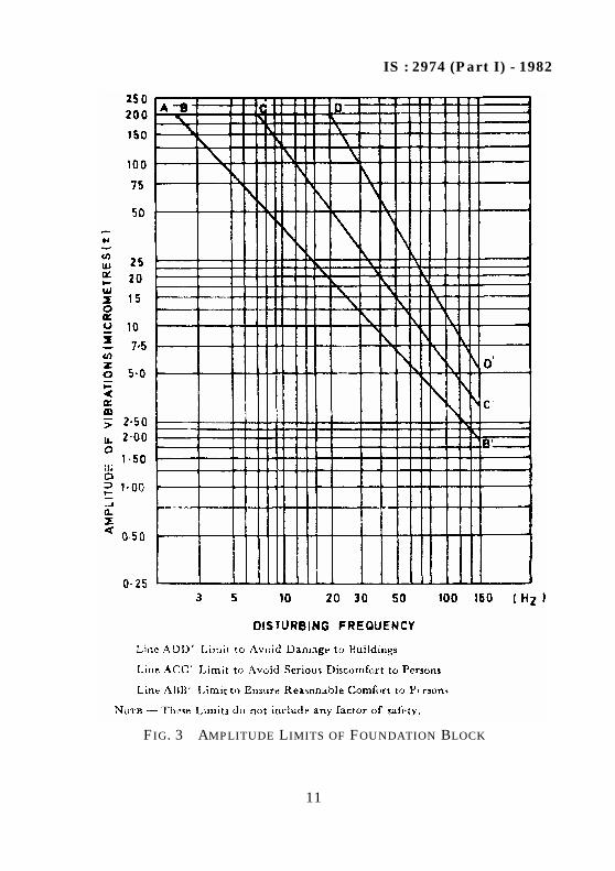
5.3.2 Limitations of Vibration Amplitude to Avoid Damage toMachinery — The damage in neighbouring buildings due to resonancewill be negligible if the amplitude vibration of the foundation is lessthan 200 microns at frequencies below 20 Hz, where the disturbingfrequency exceed 20 Hz, a lower amplitude may be necessary forcertain installations, when a value corresponding to the frequency maybe read off line ADD of Fig. 3.
5.3.3 Limitation of Vibration Amplitude to Avoid Discomfort of Persons— For low speed machines, it is unlikely that foundations whichsatisfy 5.3.2 will produce vibrations of sufficient amplitude to bedisturbing to persons. In special cases where there are particularreasons to avoid discomfort to personnel, a low permissible amplitudecorresponding to operating frequency of machine can be read offfrom Fig. 3.
5.3.4 Limitations of Amplitude to Avoid Settlement — For most soiltypes, foundations for low speed machines designed to limitingamplitude of 200 microns will not suffer undue settlement due todynamic loads. In case of some soils like loose sands and silts inconjunction with high water table, there is a possibility of significantsettlement to occur. In all such cases, it shall be preferable toconsolidate the soil underneath the foundation.
IS : 2974 (Part I) - 1982
11
FIG. 3 AMPLITUDE LIMITS OF FOUNDATION BLOCK
IS : 2974 (Part I) - 1982
12
5.4 Concrete Foundation Design
5.4.1 General Conditions — Normally concrete block foundations aredesigned for reciprocating machines. Both the foundations andmachines are usually taken as a single body resting on an elasticbedding. (Subsoil or resilient mounting). The foundation is subject tooscillations at determinable frequencies in six degrees of freedom(Fig.2).
Pile foundations may be used in cases where the soil conditions areunsuitable to support block foundation or when natural frequency ofthe block foundations needs to be raised in cases where it is impossibleto alter dimensions or when amplitudes or settlement or both need tobe reduced.
Cellular foundations may be used in special cases where it isnecessary to maintain the rigidity of a block foundation but with masssaving of concrete. Wherever possible provision shall be made incellular foundations to add mass by filling the voids to adjust thenatural frequency of foundation block provided this does not result inadditional settlement.5.4.2 Dimensions of Concrete Foundation Blocks — For initialdimensioning of the concrete foundation blocks, the following empiricalrules may be allowed.5.4.2.1 Mass of the foundation shall be greater than that of themachine.5.4.2.2 The eccentricity of foundation system along axis XX/ shallnot exceed 5 percent of the length of the corresponding side of thecontact area. In addition, centre of gravity of machine and foundationshall be if possible below the top of foundation block.5.4.2.3 To ensure reasonable stability in the case of vertical machines,the total width of the foundation (measured to right angles to shaft)shall be at least equal to the distance from the centre of the shaft tothe bottom of the foundation. In case of horizontal machines, wherecylinders are arranged laterally the width shall be greater.5.4.2.4 The proportion of foundation block shall be such to ensurestability.5.4.3 Final Design of Foundation Blocks — The final dimensions of aconcrete foundation shall be derived from vibration calculations andshall consider:
a) The dimensions of foundations by empirical rules,b) The bearing pressure due to dead and imposed load,c) The natural frequencies of the system for six modes of vibrations,
IS : 2974 (Part I) - 1982
13
d) The relationship between the exciting frequency and naturalfrequency of the foundation-soil system,
e) Calculated amplitudes in the various modes of vibration, andf) Influence of water table specially when at a high level.
Appendix B gives the design procedure for an undamped system.However, damping can also be considered in certain cases.
5.4.3.1 Full value of permissible stresses for steel and concrete asspecified in IS : 456-1978* shall be allowed if dynamic loads areconsidered in detailed design by applying suitable dynamic and fatiguefactors.5.4.3.2 The following dynamic elastic modulus of concrete may be usedin design:
5.4.3.3 The soil stress below the foundations shall not exceed 80percent of the allowable stress under static loading determined inaccordance with IS : 6403-1981†. When seismic forces are consideredallowable stress in the soil shall be increased as specified in IS : 1893-1975‡.
5.4.4 Supporting foundation blocks on end-bearing or friction pilesshall be considered in cases where there is need to make a significantchange in frequency in one or more modes of vibration or dead loads.
Pile caps where used as a foundation block shall be of such a size asto meet all design criteria, and be not less than 60 cm thick.
5.4.4.1 Requirement of piled foundations — The most usual reasons foradoption of piled foundation are as follows:
a) When pressure on the soil under the block exceeds thepermissible bearing pressure;
*Code of practice for plain and reinforced concrete ( third revision ).
Grades of Concrete Dynamic Elastic Moduluskgf/cm2
M 15 250 000M 20 300 000M 25 340 000M 30 370 000
†Code of practice for determination of bearing capacity of shallow foundations ( firstrevision ).
‡Criteria for earthquake resistant design of structures ( third revision ).
IS : 2974 (Part I) - 1982
14
b) When a foundation is found to be subject to resonance, or whenan increase in the mass of the block is either unduly wasteful inmaterial or ineffective due to the danger of resonance in othermodes;
c) When a block foundation is low tuned by one mode and hightuned by other and desirable or specified frequency ratios cannotbe maintained simultaneously;
d) When the amplitudes of movement of a block foundation are inexcess of their permissible values;
e) Piled foundation shall be used when a raft foundation is liable tosuffer a differential settlement exceeding the permissible limit; and
f) Piles may be used to minimize the effect of ground borne vibrationon surrounding foundations and equipment.
5.4.4.2 Evaluation of pile soil stiffness — Pile soil stiffness factors bothin vertical and horizontal ( see IS : 9716-1981*) modes of vibrationshall preferably be determined by conducting in situ test on piles. Incases, where it becomes difficult to conduct this test, the values can betaken from some standard publications. The centre of gravity of thesystem, that is, foundation and machine shall be located within 5percent of the length of foundation to concerned axis with respect tothe centre of gravity of the pile group.
5.4.4.3 Design considerations
a) Pile-soil stiffness factors both in vertical and horizontal modes ofvibration shall be determined by conducting in situ dynamic testson piles. For preliminary design however the computative methodof estimation of pile-soil stiffness can be adopted.
b) Usually in situ dynamic tests are conducted on single pile withfree head condition. In actual practice the pile shall be used in agroup with pile heads largely restrained by the pile cap.Allowance shall be made for these factors in evaluation of pile-soilstiffness to be adopted for design. Failure to take account of thesefactors will lead to error in estimating stiffness of the system.
c) After evaluating the pile-soil stiffness, the design shall be carriedout in the same way as for the block foundation resting directlyon soil.
*Guidelines for lateral dynamic load test on piles.
IS : 2974 (Part I) - 1982
15
5.4.5 Minimum Reinforcement in Block Foundations
5.4.5.1 Minimum reinforcement in the concerete block shall be not lessthan 25 kg/m3. For machines requiring special design considerations offoundations, like machines pumping explosive gases the reinforcementshall be not less than 40 kg/m3.
5.4.5.2 The minimum reinforcement in the block shall usually consistof 12 mm bars spaced at 200/250 mm centre to centre extending bothvartically and horizontally near all the faces of the foundation block.
5.4.5.3 The following points shall be considered while arranging thereinforcements:
a) The ends of mild steel (if used) shall always be hookedirrespective of whether they are designed for tension or com-pression,
b) Reinforcement shall be used at all faces,c) If the height of foundation block exceeds one metre, shrinkage
reinforcement shall be placed at suitable spacing in all threedirections, and
d) Reinforcement shall be provided around all pits and openings andshall be equivalent to 0.50 to 0.75 percent of the cross-sectionalarea of the opening.
5.4.6 Anti-Vibration Mountings
5.4.6.1 Where it is found to be impracticable to design a foundationconsisting of a simple concrete block resting on the natural soils to givesatisfactory dynamic characteristics, it may be possible to reduce thetransmitted vibrations to acceptable levels by means of anti-vibrationmounting.
5.4.6.2 Depending upon the nature of the machinery and theinstallation, the anti-vibration mounting may be used:
a) Between machinery and foundation, andb) Between a foundation block and a supporting system.
6. CONSTRUCTION
6.1 Concrete — Concrete strength shall be specified on the basis of28-day cube strength. The concrete grade shall be at least M-15(according to IS : 456-1978*).
*Code of practice for plain and reinforced concrete ( third revision ).
IS : 2974 (Part I) - 1982
16
6.2 Continuity of Work — Foundation block shall preferably be castin single continuous operation. In case of very thick blocks (exceedingabout 5 m) if needed, construction joints can be provided. In such aevent construction joint shall be suitably designed by the designengineer and shown in working drawing. In the event of an unforseeninterruption in concrete, the resulting unavoidable joint shall beconsidered as a construction joint and treated in the same way as cons-truction joints.
6.3 Cement Grout
6.3.1 Cement grout used for fitting or embedding shall consist of onepart of Portland cement and two parts of clean sharp sand mixed to amoist consistency sufficient to facilitate the grout being fully workedunder all seatings. Quick setting cement shall not be used.
6.3.2 Additives may be employed to give non-shrink properties tocement grout. In this case the ratio of cement and sand may be variedaccording to the instruction of manufacturer.
6.3.3 Cement grout shall be placed within a period commensurate withcement type but not later than one hour from the time of mixing.
6.4 Grouting
6.4.1 All metallic and concrete surfaces shall be thoroughly cleanedand washed to clean all dirt, oil, grease, loose particles and cementlaitance. The concrete surfaces shall be roughened and saturated withclean water and kept wet for at least 24 hours and all surplus waterremoved and surfaces cleaned, oil free with compressed air if requiredbefore commencement of grouting.
6.4.2 Provision shall be made if required to avoid trapping air. Airrelief holes shall be provided, if necessary.
6.4.3 Forms shall be high enough to provide a head of the grout on allsides which shall be about 150 mm high on side from which cement groutis to be poured. Forms shall be placed with sufficient clearance to theedges of the bases to enable the grout to be properly worked into position.
6.4.4 Forms shall be strong and secure and well covered to preventleakage. The cement grout shall be poured from one side to avoidforming air pockets and be carried out continuously withoutinterruption so that filling is continuous and dense.
6.4.5 On completion of the curing of the grout underfill the machineshall be finally checked to ensure that its alignment is acceptable.
6.4.6 Exposed surfaces of grout and concrete shall be prepared andgiven two coats of an oil and alkali resistant coating.
IS : 2974 (Part I) - 1982
17
7. TESTING AND MEASUREMENT OF VIBRATION
7.1 General — Testing of a foundation block prior to the initialrunning of the machinery may, where warranted be carried out todetermine the natural frequencies in various modes of vibration andthe amplitudes due to dynamic forces likely to occur either duringnormal running or during emergency or adverse running conditions ofthe machine. The observation can also be made during the operation ofmachines.
7.2 Excitation — In case where blocks are to be tested prior to therunning of machines, foundation blocks may be excited either by anelectromagnetic or hydraulic vibrator. The block shall be excited insame modes of vibration as is expected from the operating machinery.The amplitudes of motion which can be induced with a scale downdisturbing force may be significantly smaller than those expected inthe operation of machine. Allowance may have to be made for the non-linearity of soil response.
7.3 Measurements
7.3.1 The vibrations shall be measured by transducers having a linearresponse over the range 2 to 200 Hz. The accuracy of transducers shallbe better than 10 percent and they shall respond to a uniaxial motionwith more than 10 percent cross sensitivity.
7.3.2 The transducers shall be preferably piezo electric type or geo-phones meeting the requirements as in 7.3.1.
7.3.3 The transducers shall be mounted firmly to the foundation. Thetransducers shall not be merely rested on the foundation or held withhand.
7.3.4 Transducers shall preferably be placed on extremities of theupper-most surface of the block and as near as possible to the axis of Xand γ ( see Fig. 1 ).
7.3.5 In order to gain full picture of the behaviour of a block, it shall bedesirable to use a multiple channel recorder with ‘filter’, single channelrecorder can also be used in small installations.
7.3.6 It shall be preferable to use Vibration Analyser which canmeasure frequency and amplitude of vibration simultaneously.
IS : 2974 (Part I) - 1982
18
A P P E N D I X A( Clause 3.1 )
NOTATIONS
SYMBOL DESCRIPTION UNIT
A Area of foundation in contact with soil cm2
Ax Horizontal amplitude of foundation subjected tohorizontal force Px and moment Mt
cm
Az Vertical amplitude of foundation subjected tovertical force Pz
cm
A Rotational amplitude of foundation subjected tohorizontal force Px and moment Mi
radian
C Damping constant dimension- less
Cc Critical damping kg-s/cm
Cu Coefficient of elastic uniform compression of soil kg/cm3
C Coefficient of elastic uniform shear of soil kg/cm3
C Coefficient of elastic non-uniform compressionof soil
kg/cm3
e Eccentricity of eccentric weight of rotating parts cm
f Frequency c/s
fn Natural frequency c/s
fn1,fn2 First and second natural frequencies of founda-tion subjected to horizontal vibration
c/s
fn1,fn2,fn3 First, second and third natural frequencies offoundation when centre of gravity of mass ofmachine and foundation and the centroid ofthe foundation contact area with soil lies onvertical plane but not on the same verticalline
c/s
fnx Horizontal resonance frequency of foundationand soil system
c/s
fnz Vertical resonance frequency of foundation andsoil system
c/s
τ
IS : 2974 (Part I) - 1982
19
SYMBOL DESCRIPTION UNIT
fn Rotational resonance frequency of foundationand soil system
c/s
h Height of the top surface of the foundationabove the centre of gravity of the foundationand machine
cm
I Moment of inertia of contact area with respectto the axis of rotation passing through thecentroid of the area
cm4
k Stiffness of spring kg/cm
L Distance from mass centre of gravity of thevibrating system with respect to the axis ofrotation
cm
Mi Dynamic moment kg/cm
Mm Mass moment of inertia of the vibrating systemwith respect to the axis of rotation passingthrough C G of the system
kg-cm-s2
Mmo Mass moment of inertia of the vibrating systemwith respect to the axis of rotation passingthrough centroid of contact area offoundation with soil
kg-cm-s2
m Mass of vibrating system kg-s2/cm
mo Mass of eccentric weight of rotating parts kg-s2/cm
Px Oscillating force applied at the centre of gravityof vibrating mass
kg
W Weight of foundation and machine kg
Eccentric distance from centroid of contact areaof foundation with soil to the C G of mass ofmachine and foundation
cm
ω Circular frequency radian/s
n Circular natural frequency radian/s
IS : 2974 (Part I) - 1982
20
A P P E N D I X B( Clause 5.4.3 )
ANALYSIS FOR THE DETERMINATION OF NATURALFREQUENCIES AND AMPLITUDES OF FOUNDATIONS
ACCOMPANIED BY SIMULTANEOUS ROTATION,SLIDING AND VERTICAL DISPLACEMENT (MASS
SPRING ANOLOGY)
B-1. Limiting Natural Frequencies — The limiting naturalfrequencies shall be calculated as follows:
B-2. Check on Design
B-2.1 When the centre of gravity of mass of machine and foundationand centroid of contact area of foundation lie on the same vertical line,the vertical vibration of foundation is independent of vibrations inhorizontal direction and rotation about the horizontal axis. Thenatural frequencies should be calculated as follows:
where γ = Mm/Mmo.Amplitudes are calculated as follows:
IS : 2974 (Part I) - 1982
21
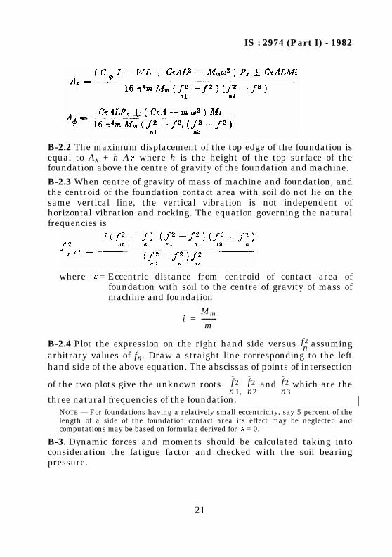
B-2.2 The maximum displacement of the top edge of the foundation isequal to Ax + h A where h is the height of the top surface of thefoundation above the centre of gravity of the foundation and machine.
B-2.3 When centre of gravity of mass of machine and foundation, andthe centroid of the foundation contact area with soil do not lie on thesame vertical line, the vertical vibration is not independent ofhorizontal vibration and rocking. The equation governing the naturalfrequencies is
where = Eccentric distance from centroid of contact area offoundation with soil to the centre of gravity of mass ofmachine and foundation
B-2.4 Plot the expression on the right hand side versus assumingarbitrary values of fn. Draw a straight line corresponding to the lefthand side of the above equation. The abscissas of points of intersection
of the two plots give the unknown roots and which are the
three natural frequencies of the foundation.NOTE — For foundations having a relatively small eccentricity, say 5 percent of thelength of a side of the foundation contact area its effect may be neglected andcomputations may be based on formulae derived for = 0.
B-3. Dynamic forces and moments should be calculated taking intoconsideration the fatigue factor and checked with the soil bearingpressure.
iMm
m----------=
f 2 n
f2n1,
f2n2
f2n3
IS : 2974 (Part I) - 1982
22
( Continued from page 2 )
Foundations Subject to Dynamic Loads Subcommittee, BDC 43 : 1
Convener Representing
SHRI T. K. D. MUNSI Engineers India Limited, New Delhi
Members
SHRI J. K. BAGCHI ( Alternate toShri T. K. D. Munsi )
SHRI N. K. BASU Cemindia Company Limited, Bombay
SHRI CHANDRA PRAKASH Central Building Research Institute (CSIR),Roorkee
DIRECTOR (TCD) Central Electricity Authority, New Delhi
DY DIRECTOR (TCD) ( Alternate )
DR M. K. GUPTA University of Roorkee, Roorkee
SHRI A. P. MUKHERJEE Metallurgical & Engineering Consultants (India)Limited, Ranchi
SHRI A. RAMA RAO ( Alternate )
SHRI A. K. MUKHERJEE Development Consultants Limited, Calcutta
SHRI S. K. MANDAL ( Alternate )
SHRI P. C. NAG National Thermal Power Corporation Limited,New Delhi
SHRI ASHOK TREHAN ( Alternate )
SHRI M. V. PANDIT Bharat Heavy Electricals Limited, Bhopal
SHRI E. C. H. C. REDDY ( Alternate )
SHRI D. H. PATEL The Fertilizer (Planning & Development) IndiaLimited, Dhanbad
SHRI S. P. GARAI ( Alternate )
DR P. SRINIVASULU Structural Engineering Research Centre (CSIR),Madras
DR N. LAKSHMANAN ( Alternate )
SHRI O. S. SRIVASTAVA Cement Corporation of India, New Delhi
SHRI S. K. CHATTERJEE ( Alternate )
DR V. V. S. RAO Nagadi Consultants Private Limited, New Delhi
SHRI M. PRIYA KUMAR ( Alternate )
Bureau of Indian StandardsBIS is a statutory institution established under the Bureau of Indian Standards Act, 1986 to promoteharmonious development of the activities of standardization, marking and quality certification ofgoods and attending to connected matters in the country.
CopyrightBIS has the copyright of all its publications. No part of these publications may be reproduced in anyform without the prior permission in writing of BIS. This does not preclude the free use, in the courseof implementing the standard, of necessary details, such as symbols and sizes, type or gradedesignations. Enquiries relating to copyright be addressed to the Director (Publications), BIS.
Review of Indian StandardsAmendments are issued to standards as the need arises on the basis of comments. Standards are alsoreviewed periodically; a standard along with amendments is reaffirmed when such review indicatesthat no changes are needed; if the review indicates that changes are needed, it is taken up forrevision. Users of Indian Standards should ascertain that they are in possession of the latestamendments or edition by referring to the latest issue of ‘BIS Catalogue’ and ‘Standards : MonthlyAdditions’.This Indian Standard has been developed by Technical Committee : BDC 43
Amendments Issued Since Publication
Amend No. Date of IssueAmd. No. 1 November 1985
BUREAU OF INDIAN STANDARDSHeadquarters:
Manak Bhavan, 9 Bahadur Shah Zafar Marg, New Delhi 110002.Telephones: 323 01 31, 323 33 75, 323 94 02
Telegrams: Manaksanstha(Common to all offices)
Regional Offices: Telephone
Central : Manak Bhavan, 9 Bahadur Shah Zafar MargNEW DELHI 110002
323 76 17323 38 41
Eastern : 1/14 C. I. T. Scheme VII M, V. I. P. Road, KankurgachiKOLKATA 700054


![Carbamoylation of Amino Acids, Peptides, and … › ... › 35 › 11 › 2974.full.pdf[CANCER RESEARCH 35, 2974 2984, November 1975] Carbamoylation of Amino Acids, Peptides, and](https://static.documents.pub/doc/80x56/5f17f5ceda1d34140355450f/carbamoylation-of-amino-acids-peptides-and-a-a-35-a-11-a-2974fullpdf.jpg)


