Disclosure to Promote the Right To Information Whereas the Parliament of India has set out to provide a practical regime of right to information for citizens to secure access to information under the control of public authorities, in order to promote transparency and accountability in the working of every public authority, and whereas the attached publication of the Bureau of Indian Standards is of particular interest to the public, particularly disadvantaged communities and those engaged in the pursuit of education and knowledge, the attached public safety standard is made available to promote the timely dissemination of this information in an accurate manner to the public. इंटरनेट मानक “!ान $ एक न’ भारत का +नम-ण” Satyanarayan Gangaram Pitroda “Invent a New India Using Knowledge” “प0रा1 को छोड न’ 5 तरफ” Jawaharlal Nehru “Step Out From the Old to the New” “जान1 का अ+धकार, जी1 का अ+धकार” Mazdoor Kisan Shakti Sangathan “The Right to Information, The Right to Live” “!ान एक ऐसा खजाना > जो कभी च0राया नहB जा सकता ह ै” Bhartṛhari—Nītiśatakam “Knowledge is such a treasure which cannot be stolen” IS 4760 (2002): Domestic Cooking Ranges Including Grillers for Use with Liquefied Petroleum Gases [MED 23: Mechanical Engineering]
Transcript
Disclosure to Promote the Right To Information
Whereas the Parliament of India has set out to provide a practical regime of right to information for citizens to secure access to information under the control of public authorities, in order to promote transparency and accountability in the working of every public authority, and whereas the attached publication of the Bureau of Indian Standards is of particular interest to the public, particularly disadvantaged communities and those engaged in the pursuit of education and knowledge, the attached public safety standard is made available to promote the timely dissemination of this information in an accurate manner to the public.
इंटरनेट मानक
“!ान $ एक न' भारत का +नम-ण”Satyanarayan Gangaram Pitroda
“Invent a New India Using Knowledge”
“प0रा1 को छोड न' 5 तरफ”Jawaharlal Nehru
“Step Out From the Old to the New”
“जान1 का अ+धकार, जी1 का अ+धकार”Mazdoor Kisan Shakti Sangathan
“The Right to Information, The Right to Live”
“!ान एक ऐसा खजाना > जो कभी च0राया नहB जा सकता है”Bhartṛhari—Nītiśatakam
“Knowledge is such a treasure which cannot be stolen”
“Invent a New India Using Knowledge”
है”ह”ह
IS 4760 (2002): Domestic Cooking Ranges Including Grillersfor Use with Liquefied Petroleum Gases [MED 23: MechanicalEngineering]
IS 4760 : 2002 (Reaffirmed 2008)
Indian Standard
DOMESTIC COOKING RANGES INCLUDING GRILLERS FOR USE WITH LIQUEFIED
PETROLEUM GASES — SPECIFICATION ( Third Revision )
B U R E A U O F I N D I A N S T A N D A R D S MANAK BHAVAN, 9 BAHADUR SHAH ZAFAR MARG
NEW DELHI 110002
November 2002 Price Group 8
Domestic and Commercial Gas Burning Appliances (Pressure Type) Sectional Committee, ME 23
FOREWORD
This Indian Standard (Third Revision) was adopted by the Bureau of Indian Standards, after the draft finalized by the Domestic and Commercial Gas Burning Appliances (Pressure Type) Sectional Committee had been approved by the Mechanical Engineering Divisional Council
This standard was first published in 1968 and revised in 1979 and m 1992 Since then many suggestions were received for its improvement and with the result three amendments were issued This standard is revised again to incorporate the amendments issued and the suggestions received from time-to-time In this revised standard requiremenls relating to grillers range has been included
This standard shall not be made applicable for those appliances not having thermostats
In preparing this standard, assistance has been derived from BS 2491 1963 'Specification for domestic cooking appliances for use with liquefied petroleum gases', issued by the British Standard Institution
This standard is one of a series of Indian Standards on various domestic and commercial gas burning appliances (pressure type) used with LPG General requirements of this equipment are covered in IS 5116 1996 'General requirements for domestic and commercial equipment for use with LPG (third revision)', which is a necessary adjunct to this standard Should, however, any deviation exist between the requirements given in IS 5116 and those of this standard, provisions of the latter shall apply Other standards published so far in this series are IS 4246 2002 'Domestic gas stoves for use with liquefied gases (fifth revision)', IS 4473 2002 'Domestic gas ovens for use with liquefied gases (first revision)', IS 4760 2002 'Domestic cooking ranges for use with liquefied gases (third revision)', and IS 11480 1998 'Domestic gnlleis for use with liquefied gases (first revision)'
The Domestic and Commercial Gas Burning Appliances (Pressure Type) Sectional Committee examined EN 30 1979 'Domestic cooking appliance burning gas' published by European Committee for Standardization The deviations are given in Annex K It may be noted that gas stove which passes as per IS 4246 will pass all the requirements of categories II23, II2HL3, II2H3 and II2L3 appliances specified in EN 30 1979
The composition of the Committee responsible for the preparation of this standard is given m Annex M
For the purpose of deciding whether a particular requirement of this standard is complied with, the final value, observed or calculated, expressing the result of a test or analysis, shall be rounded off in accordance with IS 2 1960 'Rules for rounding off numerical values (revised)' The number of significant places retained in the rounded off value should be same as that of the specified value in this standard
AMENDMENT NO. 1 JULY 2004 TO
IS 4760 : 2002 DOMESTIC COOKING RANGES INCLUDING GRILLERS FOR USE WITH LIQUEFIED
PETROLEUM GASES — SPECIFICATION ( Third Revision )
( Page 1.clause 1.1 line 5 ) — Substitute '2.942 kN/m2 (30 gf/cm2)' for '2 942 kN/m2 (30 gf/cm2)' and wherever appears in the text.
( Page 4 clause 22.3, line 5 ) — Substitute '2.452 kN/m2 (25 gf/cm2) for '2 452 kN/m2 (25 gf/cm2)' and wherever appears in the text.
( Page 5, clause 28.3) — Substitute the following for the existing clause: '28.3 It shall be possible to reduce the maximum consumption rate of the burner to the extent given below or lower by providing a fixed simmer orifice in the gas tap:
a) For burners up to 60 1/h gas rate, 35 percent of the rated capacity; and b) For burners above 60 1/h gas rate, 22 l/h or 26 percent of the rated
capacity whichever is higher.' ( Page 5. clause 29.3, lines 3 and 4 ) — Substitute '2.452 kN/m2 to
3 432 kN/m2 (25 gf/cm2 to 35 gf/cm2 for '2 452 kN/m2 to 3 432 kN/m2
(25 gf/cm2 to 35 gf/cm2)' and wherever appears in the text.
(MED 23) Reprography Unit, BIS, New Delhi, India
IS 4760 : 2002
Indian Standard
DOMESTIC COOKING RANGES INCLUDING GRILLERS FOR USE WITH LIQUEFIED
PETROLEUM GASES — SPECIFICATION ( Third Revision )
1 SCOPE
1.1 This standard specifies construction, operation, safely requirements and tests for domestic cooking ranges including grillers, for burning gases at a rate not exceeding 1 500 g/h. intended for use with liquefied petroleum gases at 2 942 kN/m2 (30 gf/cm2) gas inlet pressure
1.1.1 Cooking ranges shall be classified as follows
a) Top or Surface range — A unit designed for installation in, or on a counter top It may have top burners, a grilles a deep well cooker, or any combination thereof
b) Oven range — A range designed for installa-tion in a cabinet, wall or partition, or for instal-lation on a counter It may be a separate oven, may be equipped with a griller that uses the oven burner, or the oven may serve as a gnller unit with a burner m the upper portion of the oven
c) Griller range — May have an open top or enclosed, may have a separate griller
d) Combination of (a), (b) or (c) above, or any other domestic cooking device that may be designed for similar installation
NOTE — The requirements for top or surface ranging having top burners and gnllers and griller ranges having gnller only have been excluded from this standard and covered in IS 11480
1.1.2 For convenience, this standard has been divided into three sections as follows
Section I Construction Section 2 Performance Secuon 3 General
2 REFERENCES The standards given at Annex A contain provisions which, through reference in this text, constitute provision of this standard At the time of publication, the editions indicated were valid All standards are subject to revision, and parties to agreements based on this standard are encouraged to investigate the possibility of applying the most recent edition of the standards
3 TERMINOLOGY
For the purpose of this standard, definitions given in IS 6480 shall apply.
SECTION 1 CONSTRUCTION
4 GENERAL
4.1 In addition to the relevant requirements given m 4 ot IS 5116, the requirement given in 4.1.1 shall apply
4.1.1 No pressure regulator shall be included as a part of the range
5 MATERIALS
5.1 The relevant requirements given in 5 of IS 5116 shall apply
5.2 Matenal for gnller burner where food is placed under it shall be of non-corrosive materials
5.3 Grill trays and grill shall be made of non-corrosive material or appropriately treated to resist corrosion
5.4 Glass for grill door, if provided, shall be heat resistant
6 DESIGN FOR MAINTENANCE
6.1 In addition to the relevant requirements given in 6 of IS 5116, the requirements given in 6.2 to 6.5 shall apply
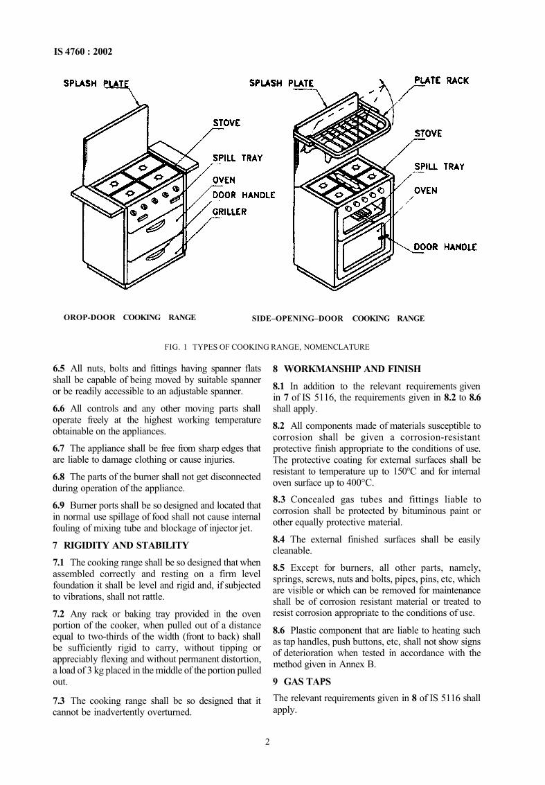
6.2 The cooking range including all the component parts (see Fig 1) shall be easy to clean and to maintain in a good working order
6.3 Burners and parts of burners only of same capacity in the same model shall be interchangeable or replaceable without effecting performance
6.4 Parts, which are intended to be removable by the user, shall be easy to replace correctly, and incapable of being assembled incorrectly
1
IS 4760 : 2002
OROP-DOOR COOKING RANGE SIDE–OPENING–DOOR COOKING RANGE
FIG. 1 TYPES OF COOKING RANGE, NOMENCLATURE
6.5 All nuts, bolts and fittings having spanner flats shall be capable of being moved by suitable spanner or be readily accessible to an adjustable spanner.
6.6 All controls and any other moving parts shall operate freely at the highest working temperature obtainable on the appliances.
6.7 The appliance shall be free from sharp edges that are liable to damage clothing or cause injuries.
6.8 The parts of the burner shall not get disconnected during operation of the appliance.
6.9 Burner ports shall be so designed and located that in normal use spillage of food shall not cause internal fouling of mixing tube and blockage of injector jet.
7 RIGIDITY AND STABILITY
7.1 The cooking range shall be so designed that when assembled correctly and resting on a firm level foundation it shall be level and rigid and, if subjected to vibrations, shall not rattle.
7.2 Any rack or baking tray provided in the oven portion of the cooker, when pulled out of a distance equal to two-thirds of the width (front to back) shall be sufficiently rigid to carry, without tipping or appreciably flexing and without permanent distortion, a load of 3 kg placed in the middle of the portion pulled out.
7.3 The cooking range shall be so designed that it cannot be inadvertently overturned.
8 WORKMANSHIP AND FINISH
8.1 In addition to the relevant requirements given in 7 of IS 5116, the requirements given in 8.2 to 8.6 shall apply.
8.2 All components made of materials susceptible to corrosion shall be given a corrosion-resistant protective finish appropriate to the conditions of use. The protective coating for external surfaces shall be resistant to temperature up to 150°C and for internal oven surface up to 400°C.
8.3 Concealed gas tubes and fittings liable to corrosion shall be protected by bituminous paint or other equally protective material.
8.4 The external finished surfaces shall be easily cleanable.
8.5 Except for burners, all other parts, namely, springs, screws, nuts and bolts, pipes, pins, etc, which are visible or which can be removed for maintenance shall be of corrosion resistant material or treated to resist corrosion appropriate to the conditions of use.
8.6 Plastic component that are liable to heating such as tap handles, push buttons, etc, shall not show signs of deterioration when tested in accordance with the method given in Annex B.
9 GAS TAPS The relevant requirements given in 8 of IS 5116 shall apply.
2
IS 4760 : 2002
10 INJECTOR JETS
The relevant requirements given in 9 of IS 1516 shall apply 11 BURNERS 11.1 In addition to the relevant requirements given in 10 of IS 5116, the requirements given in 11.2 to 11.5 shall apply 11.2 For burners having centre flame, provision shall be made to protect the centre flame from pans resting directly on burner top and smothering the centre flame 11.3 The cooking range shall have one burner having a rating of at least 1 490 kcal/h, based on net calonfic value of the gas (when using commercial LPG)
11.4 If a pilot burner is fitted, it shall be easily removable for cleaning All pilots flames shall be protected as far as possible by design and position against flame diminution or extinction by draught, products of combustion, overheating, condensation, corrosion or matter falling from above
11.4.1 If pilot burner is provided, the gas inlet to the pilot and the main burner shall close if the pilot gets extinguished
11.5 The handle of the tilt-able oven burner shall be clearly visible and easy to operate
12 DRAUGHT DIVERTER
The relevant requirements given in 11 of IS 5116 shall apply
13 FLUE OUTLET
The relevant requirements given m 12 of IS 5116 shall apply
14 PILOTS
The relevant requirements given in 13 of IS 5116 shall apply
15 FLAME FAILURE DEVICE The relevant requirements given in 14 of IS 5116 shall apply
16 BURNER PAN SUPPORTS
16.1 The design of the pan supports shall be such that It is practicable to support a pan of 100 mm diameter, over at least one top burner without the use of the loose rings, and such that a pan of 125 mm diameter remains stable over each burner Prongs of the support shall have suitable taper to accommodate round bottom pans 16.1.1 Loose pan supports shall be so designed that they cannot firmly placed in other than proper position
17 SPILLAGE COLLECTION
17.1 A tray or other receptacle shall be provided to collect spillage from pans over any top burner and shall be capable of holding at least 300 ml.
17.2 Spillage tray shall be easily cleanable.
17.3 The grill drip tray shall conform to 13 of IS 11480.
18 GRILL DESIGN 18.1 There shall be adequate clearance between the gnll and the tray beneath it to allow for satisfactory grilling and the insertion of a pie dish size 3 (see Fig 2)
18.1.1 The height of the grill pan grid shall be adjustable for two or more positions
18.2 Cooking range with a high level grill, or independent wall fixing grillers, which may give rise to high temperatures above them, shall be tested to ensure that the appliances do not constitute a fire hazard when installed
19 COOKING RANGE DOORS
19.1 Drop doors shall be such that when opened fully, they shall lie and remain essentially m a horizontal position
19.1.1 All side-hinged oven doors shall open through at least 100°
All dimensions in millimetres FIG 2 PIE DISH
3
IS 4760 : 2002
19.2 The doors and hinges shall show no sign of crack or distortion when tested according to 19.2.1 and 19.2.2.
NOTE — 19.2 shall not be applicable for cooking ranges (a) and (c) covered under 1.1.1.
19.2.1 For Doors Opening Downwards
a) a load of 100 N (10kgf) shall be applied uniformly on an area of 30 cm2 for 5 min at one comer of the door, the other being solidly supported (see Fig. 3a); and
b) a uniform load of 200 N (20 kgf) shall be applied over a strip of 10 cm width, running centrally for 5 min (see Fig. 3b).
19.2.2 For Door Opening Sideways A load of 200 N (20 kgf) shall be applied uniformly for 5 min over the top edge of the door (see Fig. 3c). 20 OVEN FLAME INSPECTION It shall be possible for the oven flames to be seen either directly or with the lid of a mirror. This may be done with door open.
21 INSULATION
21.1 When insulation is employed, it shall neither be exposed to air nor to flue products and it shall be uniformly and tightly packed to provide even protection and to prevent shifting.
21.2 Granular insulation shall not be used unless adequately protected against during transportation or normal use.
22 GAS THERMOSTAT
22.1 In addition to the relevant requirements given in 15 of IS 5116, the requirements given in 22.2 to 22.6 shall apply.
22.2 Thermostat shall be easy to operate at all temperatures normally attained in use.
22.3 The minimum gas flow through any thermostat by-pass shall be controlled by an orifice easily removable for cleaning. The fixed minimum by-pass shall be sufficient to maintain stable flames on the main burner at 2 452 kN/m2 (25gf/cm2) gas inlet pressure.
22.4 If the thermostat includes a device for controlling the pilot gas rate, it shall be easily removable for cleaning.
22.5 All thermostats shall have a suitable filter in the line before the gas valve.
22.6 The numbers or letters indicating the various thermostat settings shall be plainly and durably marked. FIG. 3 DOOR TESTING OF COOKING RANGES
4
IS 4760 : 2002
23 GAS INLET CONNECTION
23.1 In addition to the relevant requirements given in 18 of IS 5116, the requirements given in 23.2 shall apply.
23.2 The position of the gas inlet shall allow connection to a gas supply on either side of the appliance with the appliance fitted tight against a back wall. Ample clearance shall be provided to afford easy manipulation of standard tools when connecting the appliance to the supply line. Inlet connection at the rear end is also permitted.
24 GAS SOUNDNESS
The relevant requirements given in 16 of IS 5116 shall apply.
25 STRENGTH OF APPLIANCE
25.1 The appliance shall support, without breakage or apparent damage for a period of 15 min, a load of 1 kN (100 kgf), uniformly applied on the top. After the load has been supported for a period of 15 min, it shall be removed and the base and frame examined for any sign of breakage or deformation.
25.2 The materials used and the construction and assembly of the body of the appliance shall be such that the application of a diagonal force of 1.5 kN (150 kgf approximately) applied from front to rear, and a diagonal force 1.25 kN (125 kgf approximately) from side-to-side as given in Annex C, shall not result in a temporary defection exceeding 3 mm in the direction and plane of the horizontal component of the diagonal force. Compliance with this requirement shall be determined by the test.
NOTE — 25.2 shall not be applicable for cooking ranges (a) and (c) covered under 1.1.1.
26 PLATE RACK
26.1 Any plate rack if provided shall allow the safe racking of plates from 190 mm to 270 mm diameter. The plate rack shall be secure when normally loaded with plates.
26.2 The distance between the lowest part of the plate rack and the stove shall be not less than 330 mm.
26.3 If the cooking range is fitted as close as possible to a back wall and the plate rack is of the fold up typy, it shall neither hit the wall behind the cooker when in the raised position, nor shall it fall forward from this position.
SECTION 2 PERFORMANCE
27 GENERAL CONDITIONS OF TEST
The relevant requirements given in 19 of IS 5116 shall apply.
28 GAS CONSUMPTION
28.1 In addition to the relevant requirements given in 20 of IS 5116, the requirements given in 28.2 to 28.4 shall apply.
28.2 The gas consumption when measured by volumetric method, the apparatus shall be set up as given in Annex D. The measurement of volume shall be made with a wet gas flow meter and with minimum consumption of 6 1 or volume displacement of two revolutions of the drum which ever is higher.
28.3 It shall be possible to reduce the consumption rate of the burner to the extent given below by providing a fixed simmer orifice in the gas tap:
a) For burners up to 60 1/h gas rate, 35 percent of the rated capacity; and
b) For burners above 60 1/h gas rate, 22 1/h or 26 percent of the rated capacity whichever is higher.
28.4 Burners with a gas rate of up to 20 1/h at 2 942 kN/m2 (30 gf/cm ) gas inlet pressure and appliances incorporating piezo-electric ignition shall, however, be exempted from 28.3.
28.5 When the gas consumption of a burner is reduced to simmer as specified in 28.3, the flame shall not extinguish, blow off, strike back or form soot when tested with commercial LPG at 2 942 kN/m2
(30 gf/cm2) gas inlet pressure.
28.6 Oven and grill burners shall be exempted from the provision of 28.3 and shall not extinguish when switched over to simmer position from full on position.
29 IGNITION AND FLAME STABILITY
29.1 In addition to the relevant requirements given in 21 of IS 5116, the requirements given in 29.2 to 29.4 shall apply.
29.2 There shall be easy and safe access for lighting and relighting each burner by a match stick and it shall be easy to see that the burner is alight. Where the burner or burners are lighted by automatic ignition (battery of flint-operated) by a pilot flame, it shall not be possible for gas to be admitted to the main burner without being smoothly ignited by the pilot flame. Each burner should be at room temperature at the start of each test and should be tested in turn.
29.3 If a flame is applied to any of the outer row of burner ports when the gas is flowing, flame travel shall be complete. This applies for all pressures from 2 4S2 kN/m2 to 3 432 kN/m2 (25 gf/cm2 to 35 gf/cm2) taps being fully opened and without a pan over the burner. Burners consisting of two separate tubes, each requiring separate lighting are acceptable on oven.
5
IS 4760 : 2002
29.4 When the burner is ignited from a pilot flame, and/ or by an electric/electronic method, the ignition shall be smooth at pressure from 2 452 kN/m2 to 3 432 kN/m2 (25 gf/cm2 to 35 gf/cm2) with the burner lap turned full 'ON' and ignition shall be effected without undue delay after turning on taps.
29.5 When flame failure devices are used, these shall open fully from cold in not more than 90 s and shall close from the fully heated condition within 90 s.
30 NOISE CONTROL
The ignition of the burner flames, their operation and turning 'OFF' shall not give rise to undue or excessive noise during all the operations.
31 FLASH BACK
31.1 A vessel having diameter suitable to cover the pan support dully filled in with water, shall be placed on the burner under test. The tap of the burner shall be turned on and gas shall be allowed to flow through the burner at full rate, with lap fully opened and gas lighted. After half an hour, the flame shall be immediately reduced to simmer and then brought back to full size. The operation shall be repeated five times. No flash back shall occur during the test. This applies for all pressures from 2 452 kN/m2 to 3 432 kN/m2 (25 gf/cm2 to 35 gf/cm2).
31.2 The test described in 31.1 need not be performed on burners having rating of less than 550 kcal/h. This test is applicable to boiling burners only and does not apply to grillers.
31.3 There shall be no flash back when griller is switched 'OFF' after it has remained lighted in full 'ON' position for a period of 30 min at a nominal pressure of 2 452 kN/m2 (25 gf/cm2).
32 FORMATION OF SOOT
A vessel, 200 mm diameter, full of water, shall be placed on the burner and the burner lighted at full 'ON' position of the tap for one hour. After the test, no soot (unburned carbon) shall be deposited on the burner and on the bottom of the vessel. This applies for all pressures from 2 452 kN/m2 to 3 432 kN/m2
(25 gf/cm2 to 35 gf/cm2).
33 RESISTANCE TO DRAUGHT
33.1 There shall be no extinction of the flames on any of the burners operating at maximum consumption when the appliance is placed in a general (not localized) current of air with a velocity of 2 m/s, as measured with a rotating vane anemometer. The location of the appliance relative to neighboring walls and the direction of the draught shall be varied to correspond to likely conditions of appliance installation. This applies for all pressures from 2 452 kN/m2 to 3 432 kN/m2 (25 gf/cm2 to 35 gf/cm2).
33.2 Flame of the oven burner at 'ON' position shall not extinguish when the door is opened or closed abruptly. Oven burners on the by-pass rate, if fitted with a thermostat or adjusted to give an oven temperature of 120°C (see 35.2 and 35.3) above room temperature, if no thermostat is fitted, shall not be extinguished when the door is opened and closed with reasonable care.
33.2.1 Griller burners shall be tested over the consumption range of 50 to 100 percent at full 'ON' rate with the grill pan in position.
34 THERMOSTATS
34.1 In addition to the relevant requirements given in 21.6 of IS 5116, the requirements given in 34.2 to 34.5 shall apply.
34.2 The thermostat shall be such that the temperature in the centre of the oven with a gas inlet pressure of 3 432 kN/m2 (35 gf/cm2) is not more than 8°C in excess of the temperature obtained by the moving with a gas inlet pressure of 2 942 kN/m2 (30 gf/cm2) from any setting of thermostat. This requirement shall be tested by method given in E-1.1.
34.3 The thermostat shall be such that the two temperatures obtainable in an oven for each setting, that is, that obtained by the moving from a higher to the required setting and that obtained by moving from a lower to the required setting, do not differ by more than 6°C. This requirement shall be tested by method given in E-1.2.
34.4 The burners of cooker fitted with thermostats shall be stable when after operating in the highest position, to enable the temperature equilibrium to be contained, the control is turned sharply to its lowest position at a gas inlet pressure of 2 452 kN/m2
(25 gf/cm2). This requirement shall be tested by method given in E-1.3.
34.5 It shall be possible to meet the requirements given in 35 with oven tap fully open, by adjustment of the thermostat settings wherever necessary.
35 OVEN HEAT DISTRIBUTION
35.1 It shall be possible to raise the temperature in the middle of the oven to 210°C above room temperature in 15 min, with the baking tray placed between one-third and one-half the height of the oven measured from the base of the oven, that is, oven floor. The temperature measurement shall be done by means of a thermocouple, placed in the centre of a 50 mm blackened copper sphere (see Fig. 4).
35.2 It shall be possible to adjust the gas consumption so that the oven can be kept at a temperature which is not higher than 120°C above room temperature with the baking tray placed between one-third and one half the height of the oven measured from the base. If the
6
IS 4760 : 2002
FIG. 4 BLACKENED COPPER SPHERE FOR OVEN TEMPERATURE MEASUREMENT
oven is provided with a fixed low position, this test shall be satisfied with the tap on the low setting. The temperature measurement shall be made by the blackened copper sphere method as given in 35.1. 35.3 It shall be possible to raise the temperature in the middle of the oven to 260°C above room temperature using at the most 100 g of butane (1 090 kcal), the baking tray being placed between one-third and one-half the height of the oven measured from the base. This is applicable only to oven from 10 dm to 55 dm capacity. 35.4 The quantity of gas necessary to maintain in the middle of the oven, a temperature of 210°C above room temperature for one hour shall not exceed the valued given below, the baking tray being placed between one-third and one-half the height of the oven measures from the base:
100 NOTE — For oven capacities falling in between the oven capacities shown above the consumption will be worked by interpolation
35.5 With a temperature in the centre of the oven maintained at 210°C above room temperature, the temperature measured above the baking tray in any position in any horizontal plane shall not vary by more than 10 percent from the average temperature of that plane. This shall not be necessary when satisfactory cooking is established.
35.6 The operation of the oven shall not give rise to any obnoxious fumes.
36 VICTORIA SANDWICH CAKE BAKING TEST FOR OVENS Ovens of capacity up to 30 dm3 shall bake one cake of 180 mm diameter each concurrently: and ovens of capacity 80 dm3 to 100 dm3 shall bake two cakes of 230 mm diameter each concurrently. The details of test are laid down in Annex F.
37 TOASTING PERFORMANCE ON GRILLERS When tested as described in Annex G the total time taken to toast three successive loads including time of loading and unloading shall not exceed 11.5 min. For this test commercial LPG shall be used.
38 COMBUSTION
38.1 When tested according to the method laid down in Annex H on no account the carbon monoxide/carbon dioxide ratio of the exhaust gases of any burner, operating at any consumption at which the burner is stable at gas inlet pressure from 2 452 kN/m to 3 432 kN/m2 (25 gf/cm2 to 35 gf/cm2), exceed 0.02. The ratio shall not be exceeded either with the pan supports reversed or put in any other position or with a large skirted vessel placed over any burner.
38.2 The carbon dioxide and carbon monoxide content of the products of combustion shall be
7
IS 4760 : 2002
determined by the methcxls capable respectively of an accuracy of 0.05 percent and 0.001 percent of the volume of the sample.
39 SURFACE TEMPERATURES
39.1 Floor, Wall and Ceiling Temperature
39.1.1 The relevant requirements given in 23 of IS 5116, in addition to those given in 39.2 and 39.3 shall apply.
39.2 Under normal working conditions, the temperature, at any point on the surface of the range (other than working surface) likely to be accidentally touched, shall not exceed 120°C. The working surfaces are pan supports, stove tops, internal oven surface, grillers, griller frets and griller trays. Various points to check the surface, temperatures are shown in Fig. 5 on a conventional type cooking range.
4, 5, 13, 14 and 15 on both sides of cooking range FIG. 5 POINTS FOR DETERMINATION OF SURFACE
TEMPERATURE OF COOKING RANGE 39.3 Surfaces intended to be handled during the operation of the range shall not attain temperatures likely to cause discomfort in use after 2 hours of continuous operation.
40 THERMAL EFFICIENCY OF BOILING BURNER When tested as specified in Annex J, the thermal efficiency shall be at least 64 percent for each burner with the pan supported correctly on the pan supports.
For this test, the net calorific value of the gas shall be employed.
41 CLASSIFICATION OF TESTS
4L1 Type Tests
The following shall constitute type tests out of the performance requirements:
a) Strength of appliance (see 25); b) Gas consumption (see 28); c) Flash back (see 31) d) Resistance to draught (see 33); e) Thermostats (see 34); f) Oven heat distribution (see 35); g) Victoria sandwich cake baking test for ovens
(see 36); h) Toasting performance on grillers (see 37); j) Combustion (see 38); k) Surface temperatures (see 39); and
m) Thermal efficiency of the boiling burner (see 40).
41.2 Routine Tests
The following shall be carried out as routine tests: a) Gas soundness (see 24); b) Ignition and flame stability (see 29); c) Flash back test for materials of burners (see 5.2
of IS 5116). d) Noise control (see 30); and e) Formation of soot (see 32).
SECTION 3 GENERAL
42 INSTRUCTIONS 42.1 The appliance shall be accompanied by an instruction card giving the following information:
a) Brief instructions for installation and regula-tion which include piping and setting of ter-minal, if any;
b) Rating of the burners in kcal/h and g/h (with commercial LPG);
c) Instructions for the correct operation of the appliance;
d) Country of origin; and e) The words Tor use with commercial LPG at
2 942kN/m2 (30 gf/cm2). 43 MARKING 43.1 Each appliance shall be legibly and indelibly marked with the following:
a) Manufacturer's name and/or initials or registered trade-mark;
b) Total heat input (with commercial LPG); c) Rating of the burners in kcal/h and g/h (with
commercial LPG); d) Any special instructions for the safe use of the
appliance;
8
IS 4760 : 2002
e) For use with commercial LPG at 2 942 kN/m2
(30 gf/cm2 approximately); f) Country of origin; and g) A temperature chart corresponding to the
thermostat setting, if thermostat is provided.
43.2 BIS Certification Marking
The stoves may also be marlced with the Standard Mark.
43.2.1 The use of the BIS Standard Mark is governed by the provisions of Bureau of Indian Standards Act,
1986 and the Rules and Regulations made thereunder. The details of conditions under which the license for the use of the Standard Mark may be granted to the manufacturers or producers may be obtained from the Bureau of Indian Standards.
44 PACKING
The cooking ranges shall be packed as agreed to between the purchaser and the supplier, taking care of safety requirements as such during handling and transit to protect against damages.
ANNEX A (Clause 2)
LIST OF REFERRED INDIAN STANDARDS
IS No. 1070 : 1992 1483 : 1988 5116 : 1996
Title Reagent grade water — Specification White bread (third revision) General requirements for domestic and commercial equipment for use with LPG (third revision)
IS No. 6480 : 1988
Title Glossary of terms relating to domestic and commercial gas burning appliances (first revision)
ANNEX B
(Clause 8.6) METHOD OF TEST FOR PLASTICS COMPONENTS
B-1 METHOD
B-1.1 The test shall be made in a dry products free heating cabinet. Where the plastics is integral with, pushed on or secured to another component, the stressed condition shall either be simulated or, where practicable, the plastics part shall be assembled to the mating component.
B-1.2 Visually inspect the component to establish its initial condition. Place the stressed component in the cabinet for a continuous period of 48 h at a temperature of 60°C, after which inspect it again.
B-1.3 If during the final examination it is observed that the plastics part has sustained any fissures, distortion, blemishes or discolouration, it shall be deemed to have failed.
ANNEX C (Clause 25.2)
METHOD FOR TESTING STRENGTH OF APPLIANCE (DEFLECTION TEST)
C-1 PRINCIPLE
C-1.1 Application of a diagonal force to the uppermost member of the front or back of the body proper or body frame, relative to the base.
C-1.2 Application of a diagonal force to the uppermost member of the side of the body proper or body frame, relative to the base.
9
IS 4760 : 2002
C-2 PROCEDURE
C-2.1 The legs (or base, or both, if removable) and any ornamental finishing strips shall be removed and the body of the range firmly supported on wooden beams resting on the floor or some equally stable foundation.
C-2.2 Rigid angle iron beams shall be placed on diagonally opposite edges of the body proper or body frame in such a manner that the upper beam is along the edge of the uppermost member of the body and the lower beam is on the edge of the base of the cooker diagonally opposite the upper beam and parallel to it. The arrangement is shown in Fig. 6. In case where the design of the cooker makes it difficult to apply the test exactly as prescribed herein. The arrangement of the apparatus shall be left to the discretion of the testing agency.
C-2.3 Each end of the upper beam shall be connected to the corresponding end of the lower beam by a draw bar in series with a spring scale graduated in not greater than 1 kg intervals.
C-2.4 The tension on each draw bar shall be increased until the readings of the two scales are equal and their sum is equal to the diagonal force to be applied.
C-2.5 Deflection readings shall be made with two dial gauges graduated to 0.02 mm located respectively on the extreme ends of the uppermost edge of the open body opposite and in the same horizontal plane as the horizontal component of the applied diagonal force.
C-2.6 The temporary deflection shall be considered as the average of the readings of the two instruments in each case and it shall in no case exceed 3 mm.
FIG. 6 APPARATUS FOR DETERMINING STRENGTH OF COOKING RANGE BODIES SHOWING SET-UP FOR TESTING END-FRAMES
ANNEX D (Clause 28.2)
GAS CONSUMPTION TEST
D-1 PROCEDURE D-1.1 The cooking range shall be set as specified in 27 with the addition of a suitable device for measuring gas consumption. The wet gas meter which is an instrument commonly used for this purpose shall be set up in series with stove under test (see Fig. 7)
D-1.1.1 LPG shall be passed at 2 942 kN/m2
(30 gf/cm2) inlet pressure through the stove for a few minutes to purge the system of air and to establish the gas pressure required. Only one burner of the appliance shall be tested at a time and during the test all gas delivered to the stove shall flow through the jet of the burner being tested to be considered. The measurement of volume shall be made with a wet gas flow meter.
10
IS 4760 : 2002
FIG. 7 TEST SET-UP FOR GAS CONSUMPTION
ANNEX E (Clauses 34.2, 34.3 and 34.4)
METHOD FOR TESTING THE REQUIREMENTS OF THERMOSTATS
E-1 PROCEDURE
E-1.1 The appliance under examination shall be fed with butane gas at a normal working pressure of 2 942 kN/m2 (30 gf/cm2 approximately). At several setting between the lowest on the scale and the highest normally used the effect on the static temperature of the increase in gas pressure of 0 490 kN/m2 (5 gf/cm2) at the inlet of the appliance shall be noted by means of a thermocouple placed in the centre of 50 mm blackened copper sphere. Temperature shall be recorded after the equilibrium reaches.
E-1.2 Setting of the thermostat at the bottom, middle and top of the normal working range selected and at each of these settings, after equilibrium conditions have been established and recorded, the thermostat shall be turned down several settings and then up to
the original setting. Equilibrium shall be allowed to become established again and the temperature recorded as before by means of a thermocouple placed in the centre of a 50 mm blackened copper sphere. For each setting of the thermostat, two equilibrium temperatures of the oven shall be recorded; one in which the oven has reached its temperature from a lower temperature, and the other in which the oven has reached its temperature from a higher temperature.
E-1.3 LPG at 2 453 kN/m2 approximately (25 gf/cm2) inlet pressure shall be used and oven left full 'ON' to enable temperature equilibrium to establish. The thermostat setting shall be the highest possible. Then the control knob shall be turned sharply to its lowest position and the flames examined. The flame shall not extinguish by this process.
ANNEX F (Clause 36)
VICTORIA SANDWICH CAKE BAKING TEST FOR OVENS
F-1 INGREDIENTS F-1.1 The following ingredients shall be sufficient to make one cake of 230 mm diameter or two 180 mm diameter cakes.
Flour Baking powder Butter Sugar Eggs
120 g 10 g
120 g 120 g
2
One table spoon full of water and a pinch of salt.
F.2 METHOD
F-2.1 The sugar and butter shall be creamed with a wooden spoon to the consistency of whipped cream and each egg shall be beaten in separately. Baking powder and salt shall be folded in the sifted flour using a metal spoon and water added to it. When two cakes arc to be made, the mixture shall be equally divided between two tins and shall be placed on separate
11
IS 4760 : 2002
shelves in the oven. Baking shall be carried out according to the recommendation of the manufacturer of the oven. One tin shall be allowed to be removed first from the oven and the other tin moved into its place but no other adjustments shall be permitted. The location and orientation of the cakes in the oven shall be noted. The cakes, after removal from the oven, shall be left for cooking on a rack.
F.3 ASSESSMENT OF RESULTS
F-3.1 The results of the test shall be assessed as given below:
Diameter of Cake, mm
180 230
Time for Cooking, min
30 35
Colour of Cake
Brown Brown
F-3.2 The cakes shall rise symmetrically and a slightly domed shape shall be permitted.
F-3.3 Ideally there shall be no variation for colours between top and undersides when considered together but a reasonable departure from this ideal shall be permissible.
ANNEX G (Clauses 37)
METHOD FOR TOASTING PERFORMANCE TEST ON GRILLER
G-1 PROCEDURE
G-1.1 Machine made white bread conforming to IS 1483 or any other good quality bread, one day old, shall be cut into slice 12 mm thick and crusts shall be removed to not less than 6 mm from each edge.
G-1.2 The grill shall be arranged in the recommended position and completely covered with slices of bread; if parts of slices are to be used, they shall be placed at the centre rather than at the outside of the grid; three such loads shall be prepared that the meter read. The First load shall be placed centrally under the grill. The gas shall be lighted and a stopwatch started. The pan shall be withdrawn as soon as any part of the load is well browned, but before burning commences.
G-1.3 During the next 25 s the slices shall be tumed over on the grill grid, ensuring that the outer edges are placed over the edges of the grill grid. Any loss of area due to shrinkage shall be accounted for by spaces between the slices.
G-1.4 The grill pan shall be reinserted at the end of 25 s and the other side toasted. After a 15 s interval a load shall be changed and a second load shall be toasted in the same way, then a third load. At the end
of the third load the gas shall be tumed 'OFF' the watch stopped and the meter read.
G-1.5 The area in square centimeters over which the bread is browned (it usually approximates to a circle or rectangle) shall be determined. This shall be done for both sides of all three loads keeping the outer edges of the bread always to the edges of the grid.
G-1.6 Toasted Area
Except for small appliances of grill grid area less than 325 cm2 and table appliances the toasted area shall be not less than 200 cm2. There shall be no marked inequality of browning on the surface of the toast.
G-2 GAS CONSUMPTION
G-2.1 When tested as per procedure given in G-1, the gas consumption shall not exceed the value given by the following formula:
P = 0.9A + 315 where
P = permitted consumption of gas in kcal, and A = toasted area in cm2.
ANNEX H (Clause 38)
TEST METHOD FOR DETERMINATION OF CARBON MONOXIDE/CARBON DIOXIDE RATIO
H-1 PROCEDURE
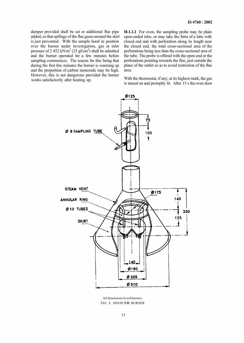
H-1.1 The ranges shall be set up as specified in 27. In addition, however, a collection hood suitable for the burners under examination shall be obtained. The hood shall be so designed that while not interfering in any way with the normal combustion of the burner, it
collects a fairly high proportion of the products of combustion. Also, it shall be such that the sample collected represents the whole of the combustion gases and not those from any particular point. A suitable collecting hood for boiling burners is shown in Fig. 8. For grillers and oven in general, a special sampling hood is shown in Fig. 9. When using this hood, the
12
IS 4760 : 2002
damper provided shall be set or additional flue pipe added, so that spillage of the flue gases around the skirt is just prevented. With the sample hood in position over the burner under investigation, gas at inlet pressure of 2 452 kN/m2 (25 gf/cm2) shall be admitted and the burner operated for a few minutes before sampling commences. The reason for this being that during the first few minutes the burner is warming up and the proportion of carbon monoxide may be high. However, this is not dangerous provided the burner works satisfactorily after heating up.
H-1.1.1 For oven, the sampling probe may be plain open-ended tube, or may take the form of a lube with closed end and with perforation along its length near the closed end, the total cross-sectional area of the perforations being less than the cross-sectional area of the tube. The probe is offered with the open-end or the perforations pointing towards the flue, just outside the plane of the outlet so as to avoid restriction of the flue area.
With the thermostat, if any, at its highest mark, the gas is turned on and promptly lit. After 15 s the oven door
All dimensions in millimetres. FIG. 8 HOOD FOR BURNER
13
IS 4760 : 2002
All dimensions in millimetres. FIG. 9 HOOD FOR OVEN
is shut, its sampling immediately begun and completed in 10 min.
H-1.2 Any of the recognized methods having the prescribed accuracy may be used for gas analysis. For carbon monoxide, it is recommended that co-indicator of prescribed accuracy or iodine pentaoxide method or catalytic method, for example, Drager method, the Katz method or infra red analysis methods may be
used. Carbon dioxide may be tested with an Orsat apparatus, the Haldane apparatus or by infra red analysis.
H-1.2 Each burner shall be examined with gas at 2 452 kN/m2 to 3 452 kN/m2 (25 gf/cm2 to 35 gf/cm2) pressure. It shall also be noted that each burner is tested with each or all the possible combinations of the other burners operating.
14
IS 4760 : 2002
ANNEX J (Clause 40)
THERMAL EFFICIENCY TEST
J-1 PROCEDURE J-1.1 The test shall be carried out by weighing the gas used. The gas shall be taken from a small bottle containing LPG weighing 1kg to 2 kg. The bottle shall be fitted with an 'ON/OFF' valve and shall be connected to a regulator which, m turn, shall be connected to a pressure gauge and to the appliance. A second 'ON/OFF' gas valve shall be inserted in the gas ways upstream of the regulator as near as possible to the gas bottle. A typical layout of set up necessary for this test is shown in Fig. 10
J-1.2 The gas shall be passed at 2 942 kN/m2
(30 gf/cm ) inter pressure through the stove for a few minutes to purge the system of air and to establish the gas pressure required Only one burner of the appliance shall be tested at a time and during the test all gas delivered to (he stove shall flow through the jet of the burner being tested The pan shall be selected and loaded in accordance with the requirements given in Table 1 and placed centrally over the burner being tested The temperature of the water t1 contained shall be noted and recorded as long as it remains constant The bottle shall be disconnected, weighed, reconnected and valves (1) and (2) opened The gas control tap shall then be opened and the gas shall be jgniled The water shall be allowed to warm up to about 80°C when stirring is commenced and continued until the end of the test The burner shall be put off when the temperature of water reaches 90°C ± 1°C.
The stirring shall be continued and the maximum temperature t2 shall be noted
Next, the valves on the bottle and the gas line shall be closed and the bottle shall be disconnected and re-weighed. It is thus possible to estimate the mass of gas used during the period taken for the water to heat up. Thermal efficiency shall be calculated by the following formula:
where E = thermal efficiency of the burner in percent, G - quantity of water in the vessel in kg, W = water equivalent of the vessel complete with
stirrer and lid, t2 = final temperature of water in °C, t1 = initial temperature of water in °C, M = gas consumption in kg, and K = calorific value of the gas in kcal/kg.
J-2 In performing the thermal efficiency test the following points shall be noted:
a) The set up shall be carefully checked for leak, before and after the test. If a leak is found after the tests, the results should be cancelled and the test repealed.
b) The room shall be free from draught. c) The initial temperature of the room shall be
between 25°C and 30°C. The water tempera-
FIG. 10 TEST SET-UP FOR THERMAL EFFICIENCY BY WEIGHT
15
IS 4760 : 2002
ture shall be within ± 2°C of the actual room temperature.
d) The net calorific value of gas is used. If this is not determined experimentally, the value may be taken as 10 900 kcal/kg for calculation.
e) At the start of the test, the burner shall be at room temperature.
f) The temperature of the water shall be measured by means of a mercury-in-glass ther-momeler of accuracy of 0.5°C the bulb of which is immersed to half the depth of the water in vessel.
g) Stirring shall be effected by means of a horizontal loop of 3 mm metal rod attached to an upright which passes through a 6 mm hole drilled in lid.
h) This lest need not be performed on burners with a gas rate less than 20 1/h at 2 942 kN/m2
(30 gf/cm2) inlet pressure. j) Accuracy of weighing balance used shall be of
0.1 g for consumption. k) Measurement and 1 g for the other weights.
m) Specific heat of aluminium is 0.214. n) For conducting thermal efficiency test, gas
from the commercial LPG cylinder (bottle) to be used. The first two-thirds of which has been allowed to evaporate (to waste or in vapour withdrawal use), the remaining one-third shall be used for test. The use of last 1kg or 2 kg of gas shall be avoided as this may contain heavy ends.
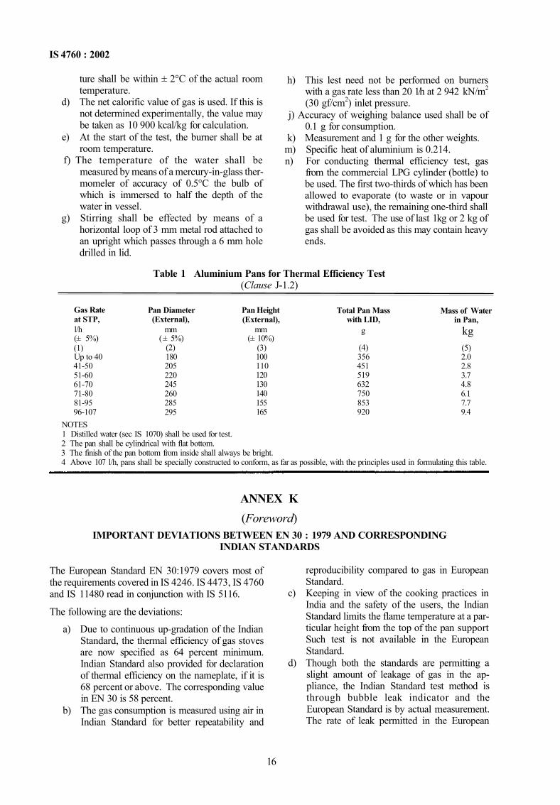
Table 1 Aluminium Pans for Thermal Efficiency Test (Clause J-1.2)
Gas Rate at STP, l/h (± 5%) (1) Up to 40 41-50 51-60 61-70 71-80 81-95 96-107
Pan Diameter (External),
mm (± 5%)
(2) 180 205 220 245 260 285 295
Pan Height (External),
mm (± 10%)
(3) 100 110 120 130 140 155 165
Total Pan Mass with LID,
g
(4) 356 451 519 632 750 853 920
Mass of Water in Pan,
kg (5) 2.0 2.8 3.7 4.8 6.1 7.7 9.4
NOTES 1 Distilled water (sec IS 1070) shall be used for test. 2 The pan shall be cylindrical with flat bottom. 3 The finish of the pan bottom from inside shall always be bright. 4 Above 107 l/h, pans shall be specially constructed to conform, as far as possible, with the principles used in formulating this table.
ANNEX K (Foreword)
IMPORTANT DEVIATIONS BETWEEN EN 30 : 1979 AND CORRESPONDING INDIAN STANDARDS
The European Standard EN 30:1979 covers most of the requirements covered in IS 4246. IS 4473, IS 4760 and IS 11480 read in conjunction with IS 5116.
The following are the deviations:
a) Due to continuous up-gradation of the Indian Standard, the thermal efficiency of gas stoves are now specified as 64 percent minimum. Indian Standard also provided for declaration of thermal efficiency on the nameplate, if it is 68 percent or above. The corresponding value in EN 30 is 58 percent.
b) The gas consumption is measured using air in Indian Standard for better repeatability and
reproducibility compared to gas in European Standard.
c) Keeping in view of the cooking practices in India and the safety of the users, the Indian Standard limits the flame temperature at a par-ticular height from the top of the pan support Such test is not available in the European Standard.
d) Though both the standards are permitting a slight amount of leakage of gas in the ap-pliance, the Indian Standard test method is through bubble leak indicator and the European Standard is by actual measurement. The rate of leak permitted in the European
16
IS 4760 : 2002
Standard is higher than the quantity specified in Indian Standard.
e) The European Standard specifies the limit of carbon monoxide in the product of combus-tion. The products of combustion are measured by carbon monoxide/carbon dioxide ratio in Indian Standard.
f) The Indian market has liquefiable petroleum gas (LPG) as the cooking gas.
European countries have three different families of gases for the same purpose. Hence the European Standard specifies the appliance which can be used and/or converted to other families of gases. LPG is categorized in the third family of gases and the production of appliances in India would be applicable only to this family.
17
IS 4760 : 2002
ANNEX M
(Foreword) COMMITTEE COMPOSITION
Domestic and Commercial Gas Burning Appliances (Pressure Type) Sectional Committee, ME 23
Organization Petroleum Conservation Research Association, New Delhi
Bharat Petroleum Corporation Ltd, Mumbai
Bombay Foods Pvt Ltd, Mumbai
Consumer Guidance Society ot India, Mumbai
Delton Industries, New Delhi
Goyal Engineers (P) Ltd, New Delhi
Hindustan Petroleum Corporation Ltd, Mumbai
Indian Institute of Petroleum, Dehra Dun
Indian Oil Corporation (R&D), Fandabad
Indian Oil Corporation (R&D) Mumbai
Khadi & Village Industries Commission Mumbai LPG Equipment Research Centre Bangalore
Mitaso Appliances Ltd Faridabad Panchal Engineer Works Ahmedabad Rama Domestic Appliances, New Delhi Sunflame Industries, Fandabad
Super Pans Ltd, Fandabad
Techno Products, Mumbai
United Works Pvt Ltd, Mumbai
Welkin India Faridabad
BIS Directorate General
Representative(s) SHRI K K DHINGRA (Chairman)
SHRI PARAMJIT SINGH (Alternate) SHRI GEORGE PAUL
SHRI S K DEY (Alternate I) SHRI SURESH NAIR (Alternate II)
SHRI D R BHAGALIA SHRI A T AZAVFDO (Alternate)
SHRI G S ABHAYANKAR SHRI RENU TALWANI (Attentate)
SHRI R C NANGIA SHRI S K GABA (Alternate)
SHRI D P GOYAL SHRI AJAY GOYAL (Alternate)
SHRI S V SAHNI SHRI K K DIXIT (Alternate)
SHRI K N DOBHAL SHRI H K MADAN (Alternate)
SHRI A K MEHATA SHRI R PAULASITYA (Alternate)
SHRI B L BANSAI SHRI A N KHAPRF (Alternate)
SHRI G L PATANKAR SHRI M L ANAND
SHRI R K VERMA (Alternate) SHRI D R SHUKLA SHRI B B PANCHAL SHRI A S KOHLI SHRI K L VERMA
SHRI A K DHINGRA (Alternate) SHRI Y R SHARMA
SHRI ANAND BHUSAN (Alternate) SHRI N K KANDELWAL
SHRI VIJAY KANDELWAL (Alternate) SHRI VICTOR MACMUL
SHRI S BHORGHARPAR (Alternate) SHRI M K GUPTA
SHRI RAHUL GUPTA (Alternate) SHRI M L CHOPRA, Director & Head (MED) [Representing Director General (Ex officio)]
Member Secretary SHRI S B ROY
Director (MED), BIS
18
Bureau of Indian Standards
BIS is a statutory institution established under the Bureau of Indian Standards Act, 1986 to promote harmonious development of the activities of standardization, marking and quality certification of goods and attending to connected matters in the country.
Copyright
BIS has the copyright of all its publications. No part of these publications may be reproduced in any form without the prior permission in writing of BIS. This does not preclude the free use, in the course of implementing the standard, of necessary details, such as symbols and sizes, type or grade designations. Enquiries relating to copyright be addressed to the Director (Publications), BIS.
Review of Indian Standards
Amendments are issued to standards as the need arises on the basis of comments. Standards are also reviewed periodically; a standard along with amendments is reaffirmed when such review indicates that no changes are needed; if the review indicates that changes are needed, it is taken up for revision. Users of Indian Standards should ascertain that they are in possession of the latest amendments or edition by referring to the latest issue of 'BIS Catalogue' and 'Standards: Monthly Additions'.
This Indian Standard has been developed from Doc : No. ME 23 ( 0488 ).