Disclosure to Promote the Right To Information Whereas the Parliament of India has set out to provide a practical regime of right to information for citizens to secure access to information under the control of public authorities, in order to promote transparency and accountability in the working of every public authority, and whereas the attached publication of the Bureau of Indian Standards is of particular interest to the public, particularly disadvantaged communities and those engaged in the pursuit of education and knowledge, the attached public safety standard is made available to promote the timely dissemination of this information in an accurate manner to the public. इंटरनेट मानक “!ान $ एक न’ भारत का +नम-ण” Satyanarayan Gangaram Pitroda “Invent a New India Using Knowledge” “प0रा1 को छोड न’ 5 तरफ” Jawaharlal Nehru “Step Out From the Old to the New” “जान1 का अ+धकार, जी1 का अ+धकार” Mazdoor Kisan Shakti Sangathan “The Right to Information, The Right to Live” “!ान एक ऐसा खजाना > जो कभी च0राया नहB जा सकता ह ै” Bhartṛhari—Nītiśatakam “Knowledge is such a treasure which cannot be stolen” IS 5116 (1996): Domestic and commercial equipment for use with LPG - General requirements [MED 23: Mechanical Engineering]
Transcript
Disclosure to Promote the Right To Information
Whereas the Parliament of India has set out to provide a practical regime of right to information for citizens to secure access to information under the control of public authorities, in order to promote transparency and accountability in the working of every public authority, and whereas the attached publication of the Bureau of Indian Standards is of particular interest to the public, particularly disadvantaged communities and those engaged in the pursuit of education and knowledge, the attached public safety standard is made available to promote the timely dissemination of this information in an accurate manner to the public.
इंटरनेट मानक
“!ान $ एक न' भारत का +नम-ण”Satyanarayan Gangaram Pitroda
“Invent a New India Using Knowledge”
“प0रा1 को छोड न' 5 तरफ”Jawaharlal Nehru
“Step Out From the Old to the New”
“जान1 का अ+धकार, जी1 का अ+धकार”Mazdoor Kisan Shakti Sangathan
“The Right to Information, The Right to Live”
“!ान एक ऐसा खजाना > जो कभी च0राया नहB जा सकता है”Bhartṛhari—Nītiśatakam
“Knowledge is such a treasure which cannot be stolen”
“Invent a New India Using Knowledge”
है”ह”ह
IS 5116 (1996): Domestic and commercial equipment for usewith LPG - General requirements [MED 23: MechanicalEngineering]
B U R E A U O F I N D I A N S T A N D A R D S MANAK BHAVAN, 9 BAHADUR SHAH ZAFAR MARG
NEW DELHI 110002
Price Group 8
Domestic and Commercial Gas Burning Appliances (Pressure Type) Sectional Committee, HMD 23
FOREWORD This Indian Standard (Third Revision) was adopted by the Bureau of Indian Standards, after the draft finalized by the Domestic and Commercial Gas Burning Appliances (Pressure Type) Sectional Committee had been approved by the Heavy Mechanical Engineering Division Council. This standard is a necessary adjunct to all the standards on gas burning appliances using liquefied petroleum gases. Some common features and general requirements of the appliances have been compiled in this standard to avoid repetition of these clauses. Liquefied petroleum gases are usually classified as butane, propane and butane propane mixtures. The appliances covered by this standard can be operated on butane, propane and butane-propane mixtures. This standard was first published in 1969 and revised in 1977 and 1985. Since then many suggestions were received for its improvement and as a result of which 7 amendments were issued. This standard has been revised to incorporate amendments issued and suggestions received from time to time. Further, the gas cock allowances are modified according to prevailing practice and only one modified nozzle for 6.4 mm bore tubing is included in this revision. For ease of reference this standard has been divided into three sections as follows:
Section 1 Construction, Section 2 Performance, and Section 3 General.
While preparing this standard, assistance has been derived from BS 5314 (Part 2) : 1976 'Specification for boiling burners', issued by the British Standards Institution. This edition 4.3 incorporates Amendment No. 1 (April 1998), Amendment No. 2 (May 2002) and Amendment No. 3 (July 2004). Side bar indicates modification of the text as the result of incorporation of the amendments. For the purpose of deciding whether a particular requirement of this standard is complied with, the final value, observed or calculated, expressing the result of a test or analysis, shall be rounded off in accordance with IS 2 : 1960 'Rules for rounding off numerical values (revised)'. The number of significant places retained in the rounded off value should be the same as that the specified value in this standard.
AMENDMENT NO. 4 MARCH 2009 TO
IS 5116 : 1996 DOMESTIC AND COMMERCIAL EQUIPMENT FOR USE WITH LPG — GENERAL
REQUIREMENTS
( Third Revision )
(Page 19, Annex M, clause M-2.1.1) — Add the following new para at the end of this clause:
'In case of mini water heater, arrange the water heater under examination so that it is as close as possible to the side and back wall of the apparatus in L-1, take note of the manufacturer's installation mstructions. Light the water heater and adjust to give maximum water temperature at the maximum heat input. Measurement shall be taken after 20 minutes operation.'
(ME 23)
Reprography Unit, BIS, New Delhi, India
IS 5116 : 1996
Indian Standard DOMESTIC AND COMMERCIAL
EQUIPMENT FOR USE WITH LPG — GENERAL REQUIREMENTS
( Third Revision ) 1 SCOPE This standard specifies general requirements and methods of test relevant to these requirements, for domestic and commercial equipment, for households and other commercial catering organizations, using liquefied petroleum gases at 2.942 kN/m2
(30 gf/cm2) gas inlet pressure. 2 REFERENCES The Indian Standards listed in Annex A are necessary adjuncts to this standard. 3 TERMINOLOGY For the purpose of this standard, the definitions given in IS 6480 : 1988 shall apply.
SECTION 1 CONSTRUCTION
4 GENERAL 4.1 The construction of all the parts of the equipment shall be sound and of high standard of workmanship and appropriate finish. The construction shall ensure durability and shall comply with the safety requirements. 4.2 Rivets, fastening screws, plugs, etc, shall not lead into gas passages, except where adequate provision has been made to ensure permanent gas-tight joints.
5 MATERIALS 5.1 Fittings and materials shall comply, where specified, with the relevant Indian Standards and shall be appropriate to the conditions arising in the part of the appliance in which they are used. The appliance shall be free from swarf, grit, and other foreign matters. Wherever practicable, rigid metal tubing shall be used for internal gas supplies integral with the appliance. If flexible tubing is used, it shall not be fitted on the outlet side of any control which is capable of cutting off the gas completely, except where screwed metal connections are fitted. The use of low pressure rubber or plastic tubing fitted or pushed on nozzle is not recommended.
5.1.1 Plastic components which are liable to heating (for example, tap handles, push buttons, etc) shall be free of fissures, distortion, blemishes and discolouration and shall not show signs of ageing when tested as given in Annex B. 5.2 The material used in the construction of the appliance or parts of the appliance shall be resistant to wear and deterioration occuring in the normal use. The burner parts shall not melt or distort when the stove burner is operated with flames flashed back for half an hour in the mixing tube. This shall be checked by the test detailed in Annex C. 5.3 All copper and copper alloy parts shall pass the mercurous nitrate test (season cracking test) when tested according to the method specified in IS 2305 : 1988. 5.4 Non-metallic materials normally in contact with the gas shall not change in weight or volume by more than 15 percent after being immersed in pentane or LPG for 72 h at room temperature, when tested according to Annex D. 5.5 The main body of the burner (including mixer head, mixing tube and burner head) shall be of substantial and durable construction. Metals having a melting point below 510°C shall not be considered acceptable for top burners while metals having a melting point below 800°C shall not be considered for oven, griller or auxiliary burners or any other combination thereof. 5.6 The components of the gas taps may be made of the following materials. Examples of suitable materials specified below are for guidance: Alloy LM 6, LM 20 Bodies — Alloy 4600 and
Alloy 4600 A of IS 617 : 1975 Alloy DCB 1
Alloy DCB 3
Alloy CZ 122
Bodies (die castings) — DCB 1 of IS 1264 : 1989 Bodies (pressure die castings) — DCB 2 of IS 1264 : 1989 Bodies, plugs (hot pressed) — Leaded brass of IS 6912 : 1985
1
IS 5116 : 1996
Alloy CZ 121
Alloy PB 102, PB 103
Alloy En 56 series
Alloy C 106, C 107
Alloy CZ 108
Nuts, etc — Type I of IS 319 : 1989 Springs (phosphour bronze) — Grade I and II of IS 7608 : 1987 Springs (stainless steel) — Grade 1 of IS 4454 (Part 4) : 1975 Tubes — Grade DHP and DPA of IS 2501 : 1985 Washers — Alloy CuZn37 of IS 410 : 1977
5.7 Drip trays, if provided, shall be made of non-corrosive material or appropriately finished and treated to resist corrosion. 6 DESIGN FOR MAINTENANCE 6.1 Every part of the appliance shall be of such construction as to be secured against displacement, distortion, warping or other damage and shall be supported to maintain a flxed relationship and reasonable conditions of handling and use so as to ensure continued compliance with these requirements. Such parts not permanently secured shall be designed so that they cannot be incorrectly assembled and cannot be improperly located or misaligned in removing or replacing during cleaning or other servicing. 6.2 Thermostats, orifices, burner ignition devices, oven and griller door springs, air shutters and other accessories and controls which may require cleaning, repair or adjustment in the field shall be readily accessible. 6.3 Condensate from the products of combustion shall not drip from the appliance to the floor. 6.4 Level An appliance when fitted according to manufacturer's instruction shall be in level. 6.5 Noise It is desirable that the intensity of noise should be as low as possible whether from burners, pilot, resonance effects in flue, water circulation, local over heating, mechanical vibration or any other case. 6.6 Handles add Knobs These shall be so constructed and fitted that they do not work loose or break easily in normal use. 6.7 Electrical Requirements Where the appliance is intended for connection to the mains electrical supply, the requirements given in 6.7.1. 6.7.2 and 6.7.3 shall be met.
6.7.1 Components Electrical components shall comply with the appropriate Indian Standards. 6.7.2 Earthing Appliances shall conform to the earthing requirements of IS 3043 : 1987. 6.7.3 Connection Any flexible cable connecting the appliances to the main electrical supply shall have a minimum useful length of 1.80 m. It shall be of 3 cords, and, if supplied for a portable appliance, shall embody strengthening cords as specified in IS 694 : 1990. With a fixed appliance it shall be possible to connect and disconnect the electric supply with the appliance fixed in its working position. 6.8 There shall be easy access to components and controls for maintenance and adjustment. 6.9 The gas and water connections should preferably be so placed that the installation pipes can easily be connected without appearing at the front. 6.9.1 It shall be possible to descale all waterways susceptible to the formation of scale. Wherever practicable, appliance shall be provided with a point for the measurement of gas pressure. This should preferably be located after all controls. 7 WORKMANSHIP AND FINISH 7.1 The finish of exposed parts shall be durable, easy to clean and not subject to excessive deterioration in normal use. Parts which come in contact with foodstuffs shall be capable of being hygienically cleaned. The finish shall, on visual examination, show no defects, such as pinholes, blisters, roughness and exposed areas of metal, which might give rise to unduly rapid deterioration in the use. The surface shall also be free from burrs and sharp edges, which might cause injury to the user with normal operation. The finished components shall meet relevant requirements covered in 7.2 to 7.4. 7.2 Vitrous-enamelled components shall meet the requirements as given in Annex E. The test shall be carried out on a specimen measuring 40 mm × 75 mm prepared from the same base metal and enamels, as the components, and processed and fired along with the components to ensure identical conditions. 7.2.1 A separate specimen shall be used for each test. 7.3 The top flat surface of the body of the appliance, if plated, shall have a coating of minimum of 10 microns of nickel followed by 0.2 microns minimum of chromium. The
2
IS 5116 : 1996 coating shall be tested as per the requirements given in 7.3.1, 7.3.2 and 7.3.3. 7.3.1 The thickness of nickel plating shall be determined by BNF jet method or any other method, such as coulometric method as specified in IS 3203 : 1982.
7.3.2 Adhesion Test
Cut a piece of a plated article, hold it in a vice and apply a coarse file to the cut edge in such a manner as to raise the deposit. There shall be no separation between the coating and the base metal and the coating shall continue to adhere to the base metal.
All dimensions in millimetres.
FIG. 1 PAINT SCRATCH TEST APPARATUS
IS 5116 : 1996
7.3.3 Corrosion Resistance The plated article shall be subjected to the test for 12 h as covered in IS 6910 : 1985. The rating shall be assigned using the methods described in IS 6009 : 1970. 7.4 Paints or Similar Finishes Surfaces finished in stoving paint or similar material shall conform to the requirements given in 7.4.1 and 7.4.2. 7.4.1 Resistance to Abrasion The apparatus required for this test shall be as shown in Fig. 1 with a 1 mm diameter steel ball
fixed at the end of a counterpoised arm which is kept horizontal. Apply the apparatus to the surface under test and move the ball, after loading with not less than 1 500 g, at 3-4 cm/s relative to the surface. If the indicator bulb lights, the surface is deemed to have been penetrated. For metallic paints a visual examination of the scratch is necessary in order to determine whether the film has been penetrated. The finish is deemed to have failed if the scratch has Jagged edges, is greater than 1 mm wide or penetrates the film. Clean the ball after each test and inspect frequently to verify that it is a 1 mm sphere.
TYPE A TURNING AXIS VERTICAL
ASYMMETRICAL
TYPE B TURNING AXIS HORIZONTAL AT RIGHT ANGLE TO FRONT OF STOVE
FIG. 2 TYPICAL TYPES OF TAP HANDLES
4
IS 5116: 1996
7.4.2 Resistance to Heating
When the appliance is operated with LPC at its normal working pressure for a continuous period of 8 h, there shall be no appreciable change of colour of any of the appliance and the finish shall not become tacky or show other signs of deterioration. This does not apply to parts which come into direct contact with the flame. After the initial burning-off period, there shall be no detectable odour from the flame when the appliance is operated normally.
7.5 Concealed Gas Supplies
Concealed tubular fittings liable to corrode shall be protected by bituminous paint or other equally protective material.
7.6 Water Supplies
All water-carrying tubing and components shall be resistance to corrosion, or shall be treated with a corrosion resistant finish both internally and externally.
7.7 Screws, Nuts, Bolts and Springs
All springs and those screws, nuts and bolts, which are visible or which are to be removed for maintenance shall be of corrosion resistant material or treated to resist corrosion.
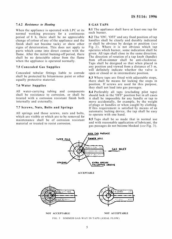
8 GAS TAPS 8.1 The appliance shall have at least one tap for each burner. 8.2 The 'ON', 'OFF' and any fixed position of tap handles shall be clearly and durably indicated or shall be obvious by design or position (see Fig. 2 ) . Where it is not obvious which tap operates which burner, some indication shall be given. All taps shall close in the same direction. The direction of rotation of a tap knob (handle) from off-on-simmer shall be anti-clockwise. Taps shall be designed so that when placed in any position and viewed from a distance of 3 m, will definitely indicate whether the valve is open or closed or in intermediate position. 8.3 Where taps are fitted with adjustable stops, there shall be means for locking the stops in position. If screws are used for this purpose, they shall not lead into gas passages. 8.4 Preferably all taps (excluding pilot taps) should lock in the 'OFF' position but in all cases it shall be impossible for any handle or tap to move accidentally, for example, by the weight of plugs or handles or when caught by clothing. If this requirement is satisfied by means of an automatic locking device, the tap shall be easy to operate with one hand. 8.5 Taps shall be so made that in normal use and with reasonable application of lubricant, the gas passages do not become blocked (see Fig. 3 ) .
ACCEPTABLE
NOT ACCEPTABLE NOT ACCEPTABLE
FIG. 3 SIMMER GAS-WAY IN TAPS (AXIAL FLOW)
5
IS 5116 : 1996
8.5.1 Taps shall be lubricated with a suitable grease, resistant to the action of the gas and capable of operating at the maximum temperature of 110°C. 8.6 Each taper plug tap shall be spring-loaded to maintain a gas-tight fit. Helical springs fitted in taps and valves shall have flattened ends, which shall be rounded before fitting. 8.7 Taper plug taps shall have dimensional allowances when in 'OFF' position given in Fig. 4. 8.8 All controls or taps shall be easy to operate at all temperatures normally attained in use. 8.9 Screws, nuts, etc, which regulate the tension of taps valve or springs, shall not loosen in operation of the appliance. It shall not be possible to cause a leak during normal manual operation of tap. 8.10 Screw-down valves shall be so designed that it is impossible to withdraw completely the valve stem in the normal operation of the tap. 8.11 Taps having an 'OFF' position shall have positive stops at the 'OFF' and simmer position except that special purpose taps (for appliance incorporating auto or self ignition device), for example, taps with simmering position in between 'OFF' and 'ON' may have a movement beyond the simmer position with a positive stop.
8.11.1 Simmer flame shall be obtained by fixed simmer orifice. 8.12 The niting means adopted shall be sufficiently robust to withstand normal use without distortion or damage. 9 INJECTOR JETS 9.1 The injector Jets shall be fixed calibrated type and it shall not be possible to loosen them without the use of tools. The dimensions of the injector Jet shall conform to the following requirements:
Across flats Projection from the face of mounting Threads
6 mm, Min 6 mm. nominal
M 5 or 1BA 9.1.1 Injector Jet shall be made of metal, with or without ceramic tip. The melting point of the metal shall not be less than 650°C. 9.2 The size of the Jet in litres per hour of flow of LPG at STP conditions shall be impressed upon it. 10 BURNERS 10.1 The construction of the burners and the assembly shall allow their dismantling from the supports easily with or without the use of tools (see Fig. 5 for guidance).
A = Top take up B = T o p ridge formation allowance C = Bearing surface above gas-way D = Circumferential seal
1.1, Min 0.4, Min 3.0, Min
2.80. Min
A1 = B1 = C1 =
Bottom teke up 1.2, Min Bottom ridge formation allowance 0.4, Min Bearing surface below gas-way 3.0, Min
All dimensions in millimetres.
FIG. 4 DETAILS OF GAS COCK ALLOWANCES
6
IS 5116 : 1996
FIG. 5 TYPICAL BURNER ASSEBLY
10.2 The burner supports shall be rigid and shall be fixed in their place. Their construction shall ensure the stability of the burners and shall prevent their undue movement in a horizontal plane. 10.3 The lightness of the joints in the burner assembly shall not depend upon adhesives or
any kind ot packmg. 10.4 If primary air regulators are used, they shall be so designed that they are not easily maladjusted by the user and the construction shall be such that primary air adjustment can be made with the burner in place ( see Fig. 6 ).
A = lnjector jet B = Throat C = Aeration control D = Locking device E = Mixing tube
FIG. 6 PRIMARY AIR CONTROLS
7
IS 5116 : 1996 10.5 If the burner is made and assembled in two or more parts they shall be so designed to provide proper self-locating arrangement so that they are always re-assembled to its original design preventing any maladjustment in their assembly. This shall also be applicable for primary air regulators. 11 DRAUGHT DIVERTER 11.1 Where an appliance is to be, ventilated to outside air. a draught diverter shall be fitted and its resistance to draught shall be tested by the method given in Annex F. The appliance shall meet the following requirements:
a) Combustion shall comply with 22, and b) Pilots shall remain stable and shall not be
extinguished and flame failure devices shall continue to function normally.
12 FLUE OUTLET 12.1 Enclosed Burner An appliance in which the burner is enclosed in a chamber, for example, a hot-food cabinet, shall be provided with a designed flue outlet. 12.2 Obstruction The flue shall be protected either by design or position against inadvertent obstruction. 12.3 Wall Staining The design and the position of the flue outlet shall be such that staining of the wall and ceiling of the room is minimized. 13 PILOTS 13.1 All pilot flames and weep terminals shall be protected as far as possible by design and position against diminution or extinction, for example, by draught, by products of combustion, by over-heating, by condensation, by corrosion, or by matters falling from above. 13.2 Ignition of the main burner from the pilot flame shall be smooth and no pilot flame shall lift, roar, or lengthen sufficiently to cause discolouration on any external surface, soot deposition or smell at working pressure between 2.452 and 3.432 kN/m2 (25 and 35 gf/cm2). 14 FLAME FAILURE DEVICE 14.1 Requirements for flame failure device shall be as under:
a) Shall prevent gas from being supplied to the main burner until the pilot flame, if provided, is established;
b) Shall, after flame failure, stop all gas flow to the main burner;
c) Shall be actuated only by a pilot flame, if provided, to ignite the main burner without failure or delay;
d) Shall open and close in times not exceeding the following limits: Operation
Opening from cold Closing from the fully heated condition
Time Manually Non-manually Operated, Operated, seconds seconds
40 90 75 90
e) Shall be free from any weakness in design which will give rise to failure to danger; and
f) Shall be protected against adjustment by unauthorized persons.
14.2 The requirements of flame failure device shall be checked by the method given in Annex G. 15 GAS THERMOSTATS 15.1 Valve Cleaning The thermostat should preferably be so designed that the valve can be withdrawn from the body and, after cleaning replaced without alteration of the temperature calibration. If it is so designed, this operation shall be possible without removing the complete thermostat from the appliance. 15.2 Bypass Any bypass orifice should either be readily accessible for cleaning or suitably protected against blockage. Thermostats for use with relay controls shall have the bypass, if any, blocked. 15.3 Calibration Marking The settings shall be indicated by easily distinguishable durable markings. 15.4 Sealing Means shall be provided to avoid interference with the calibration. 15.5 Calibration While operating the oven burner, the temperature shall be maintained to the manufacturers calibration within ±10°C. This requirement shall be tested by the method given in Annex H. 15.6 Backlash Except when the appliance is fitted with a fixed-setting thermostat, the change in temperature due to backlash shall not exceed 10°C when tested by the method given in Annex H. 16 GAS SOUNDNESS All gas carrying parts of the appliance shall be sound and these parts when connected, to form a complete assembly shall also be sound
8
IS 5116 : 1996 against any gas leakage. The complete assembly shall also be sound against any gas leakage. The complete assembly shall be checked at 14.71 kN/m2 (approx 150 gf/cm2). The details of test are given in Annex J.
17 WATER SOUNDNESS 17.1 Components Tubing, fittings, water taps, ball valves and cylinders shall comply for soundness with relevant Indian Standards. 17.2 Appliances Manufacturers shall state whether the appliance is intended for connection to a cistern or main water supply; in the former case they shall also state the maximum static head to which the appliance should be subjected, together with the recommended range of working heads. Appliances shall not leak or show any signs of distortion at a water pressure 50 percent greater than recommended maximum head and appliance intended to withstand the full water pressure, that is, with outlet water control, shall not leak or show any sign of damage or distortion at a static pressure of water of 205 MN/m2 (21 kgf/cm2) when tested by the method given in Annex K, unless there is a water surface open to atmosphere. 17.2.1 All appliances using pressure containers whatever pressure their component parts can withstand shall be able to withstand a vacuum of 49 kN/m2 (0.5 kgf/cm2) without permanent deformation taking place, unless a safety device is fitted which prevent any vacuum being formed. 17.2.2 An appliance without a water surface open to atmospheric pressure shall be fitted with:
a) a pressure relief valve, and
b) a non-return valve on the water inlet. 17.2.2.1 The pressure relief valve when provided shall be so constructed that the relieving pressure cannot exceed 60 percent of the hydrostatic test pressure of the storage vessel. The relieving pressure shall be plainly and permanently marked on the relief valve itself. 17.3 Connections Screwed water inlet and outlet connections shall have either an IS 554: 1985 taper external thread or an internal thread which is suitable for direct connections to an IS 554 : 1985 taper external thread. Further following type of connections are also acceptable. Suitable for direct connection to copper tubes to IS 2501 : 1985 and mild steel tubes to IS 1239 (Part 1) : 1990 and suitable for screwing to IS 554 : 1985 pipe threads medium and heavy. 18 GAS INLET CONNECTIONS 18.1 Nozzles shall be machined from free cutting brass or mild steel. 18.2 Where nozzles for flexible tubing are fitted, they shall be so positioned as to facilitate fitting of the tubing and also to prevent heating of the tubing to more than 60°C. Shape of nozzles is given in Fig. 7. 18.3 Screwed gas inlet and outlet connections shall have threads specified in 17.3. 18.4 The pipe/tube used for main gas rail shall be of mild steel. The wall thickness of main gas rail shall be 1.6 mm + no Iimit/–0.15 mm. The external surface of the gas rail shall be treated to resist corrosion. Any other connection made from the main gas rail shall be only metallic.
Tolerance on all Dimensions ± 0.25 All dimensions in millimetres.
FIG. 7 NOZZLE FOR 6.4 mm BORE TUBING
9
IS 5116 : 1996
SECTION 2 PERFORMANCE 19 GENERAL CONDITIONS OF TEST 19.1 During the tests the initial adjustment of appliance shall not be altered unless specifically required in the test procedure. The appliance shall be adjusted and operated in accordance with the instructions given on or issued with the appliance. Before any tests are made the appliance shall be operated at its full working temperature for a sufficient period to remove any temporary protective coating, which might interfere with observations. The gas connections and system up to and including the burners shall be examined for leaks before and after test. The performance test results shall not be valid unless the system is sound. The appliance shall be at room temperature at the start of each test unless otherwise stated. 19.2 The room in which tests are conducted shall be adequately ventilated but free from perceptible draughts. The gas/air shall be supplied to the appliance through a control valve, an adjustable pressure regulator and an accurate meter with a pressure gauge on its inlet. A pressure gauge shall be fitted to the inlet of the appliance and additional water manometer to any pressure test points on the appliance. The gas/air pressure shall be measured correct to 2.5 mm water gauge at the inlet to the appliance and controlled so that any variation does not exceed 2.5 mm water gauge. 19.3 Except where otherwise stated, the appliance shall satisfy the performance requirements using LPG. Wherever the combustion characteristics of burners are concerned, each burner shall be tested separately and in all possible combinations with other burners. This procedure shall be used for appliance with up to four burners. For appliance with larger number of burners, the test procedure becomes impossibly long and discretion shall be exercised to eliminate tests on combinations of widely separated and which are fitted in appliance of open construction are unlikely to interfere with the combustion of each other. 20 GAS CONSUMPTION 20.1 Each burner assembly under separate 'QN/OFF control shall be within ± 8 percent of the manufacturer's declared gas consumption in g/h or 1/h or heat input in kcal/h at 2.942 kN/m2 (30 gf/cm2 gas inlet pressure when measured according to 20.4. 20.2 Appliances having more than one burner, shall give within percent of the declared
heat input at the standard pressure –15 with all the taps turned on. 20.3 The gas consumption of the pilot alone shall not exceed 5 1/h at a gas inlet pressure of 2.942 kN/m2 (30 gf/cm2). 20.4 The fiow through the injector Jet at 30 gf/cm2 shall be measured with a wet gas meter using compressed air (free from oil/impurities) and converted the same at STP (27°C and 760 mm Hg). Thereafter using 0.75 as multiplying factor, the value of air fiow at STP so obtained to be converted to flow of LPG at STP.
NOTE — For the above test, one litre of LPG = 2.46 g. 20.5 The temperature of the room during the test shall be between 25°C and 30°C. 21 IGNITION AND FLAME STABILITY 21.1 There shall be some means of ignition from an easily accessible position. In addition it shall be possible to light the pilot (or burner in the absence of a pilot) directly with a match. It shall be possible to see the main burner fiames either directly or by reflection when the burner has been lit. The ignition pilot flame shall be clearly visible at the time of lighting, unless it is protected by a safety device, but not necessarily thereafter, although it is desirable that the pilot flame should be visible at all times whether protected by a safety device or not. The pilot shall be capable of igniting the main burner smoothly over the range of pressures from standard underload to overload. The smoothness of ignition of the burner shall be Judged when all the ports or Jets have ignited. 21.1.1 Where an appliance is fitted with a pilot not protected by a flame failure device, the pilot and main taps shall be designed so that it shall not be possible to turn the main gas taps 'ON' with the pilot tap 'OFF' nor shall it be possible to turn the pilot tap 'OFF' with the main gas tap turned 'ON'. Open boiling burner and grill pilot taps are exempted from this requirement. It is desirable that any burner with a rated output in excess of 5 040 kcal/h should be protected by a flame failure device. 21.2 Burner flames shall carry across to all ports or Jets on the same burner under normal working condition from full gas rate down to 75 percent of full gas rate at gas inlet pressure from 2.452 to 3.432 kN/m2 (25 to 35 gf/cm2). 21.3 It shall be possible to operate appliance with taps fully open at gas inlet pressure from 2.452 to 3.432 kN/m2 (25 to 35 gf/cm2 without the flame either extinguishing blowing off or striking back and without the formation of soot.
10
IS 5116 : 1996
21.4 Pilot flames shall be stable without lifting or soot deposition at gas inlet pressure from 2.452 to 3.432 kN/m2 (25 to 35 gf/cm2). 21.5 The flxed minimum pilot rate shall be sufficient to relight the main burner at 2.452 kN/m2 (25 gf/cm2 gas inlet pressure. 21.6 Thermostats Flame stability at bypass or maintenance rate shall meet the requirements given 21.6.1, 21.6.2 and 21.6.3. 21.6.1 Variable Setting Thermostat When tested by the method given in Annex L, the flames shall be stable at all rates from normal maximum gas rate down to and including bypass rate when the appliance door is quickly opened and closed. The flames shall also remain stable when the thermostat head is rotated rapidly in both clockwise and anti-clockwise directions. 21.6.2 Fixed Setting Thermostat When tested by the method given in Annex L, the flame shall not be permanently extinguished or flash back at maintenance rate after the doors of the appliance are opened or closed sharply 21.6.3 Protection of Rods and Phials Thermostat rods and phials shall be so positioned as to be protected from damage in normal use of the appliance.
22 COMBUSTION 22.1 On no account the carbon monoxide/ carbon dioxide ratio of exhaust gases, of any appliance operating at any consumption at which the flame is stable at gas inlet pressure from 2.452 to 3.432 kN/m2 (25 to 35 gf/cm2) shall exceed 0.02. The carbon monoxide and carbon dioxide contents of the products of combustion shall be determined by the methods capable of accuracy of 0.001 percent and 0.5 percent, respectively of the volume of the sample. This test need not be performed on burners with a gas rate of less than 20 1/h at 2.942 kN/m2 (30 gf/cm2) gas inlet pressure.
23 FIRE HAZARD AND LIMITING TEMPERATURES
23.1 Floor Wall and Ceiling Temperatures Appliances installed on or near walls and floor as intended for normal use shall not give rise in operation to wall, floor or ceiling temperature in excess of 65°C above the room temperature after 2 h operation. This requirement shall be tested by the method given in Annex M.
23.2 Surface Temperatures When operated as described in 23.1 no portion of the surface of the appliance, other than a working surface, likely to be accidently touched shall exceed 120°C (working surfaces include pan supports, oven flue outlets, grill covers and plate racks).
23.2.1 Surfaces which is normal use have to be touched for short periods (for example, tap handles), shall not have a temperature exceeding 60°C. 23.2.2 The temperature of synthetic rubber diaphragm in gas carrying components shall not exceed BOX. 23.2.3 Test given in 25.2 of IS 4246 : 2002 shall be carried out.
SECTION 3 GENERAL
24 INSTRUCTIONS Each appliance shall be accompanied by an instructions sheet, card or leaflet dealing with the following:
a) Brief instructions for installation, regulation and maintenance of the appliance. This includes setting of flue and terminal, if required;
b) For use with LPG at 2.942 kN/m2 ( 3 0 , gf/cm2);
c) Total gas consumption in g/h (1/h) (with LPG):
d) Any special instruction for use of the appliance;
e) Where cooking ranges with high level grills or independent wall flxing grills are supplied, the minimum height allowable between the top of the grill and ceiling or overhead shelf from the Are hazard point of view;
f) If threaded connections are provided on gas and water inlets and outlet, size of thread; and
g) Rating of the burners in kcal/h (with LPG). 25 PACKING 25.1 The method for packing shall be such as to minimize the damage to the appliance in transit. If governors or relay controls are unavoidably supplied loose, moving parts shall be clamped with the valve in the open position and the inlet and outlet shall be plugged.
25.1.1 All open pipe ends and connection openings shall be suitably plugged, and sealed to prevent the entry of extraneous matter.
11
IS 5116 : 1996
ANNEX A (Clause 2)
LIST OF REFERRED INDIAN STANDARDS
IS No. 319 : 1989
410 : 1977
554 : 1985
617 : 1975
694 : 1990
1239 (Part 1) 1990
1264 : 1989
2305 : 1988
2501 : 1985
Title Free cutting brass bars, rods and sections (fourth revision) Cold rolled brass sheet, strip and foil (third revision) Dimensions for pipe threads where pressure tight Joints are required on the threads (third revision) Aluminium and aluminium alloy ingots and castings for general engineering purposes (second revision) PVC insulated cables for working voltages upto and including 1 100 V ( th ird revision)
:Mild steel tubes, tubulars and other wrought steel fittings: Part 1 Mild steel tubes, (fifth revision) Brass gravity die castings (ingots and castings) ( th ird revision) Method for mercurous nitrate test for copper and copper alloys (first revision) Copper tubes for general engineering purposes (second revision)
IS No. 3043 : 1987 3203 : 1982
4454 (Part 4) 1975
6009 : 1970
6480 : 1988
6910 : 1985
6912 : 1985
7608 : 1987
Title Code of practice for earthing Methods of testing local thickness of electroplated coatings (first revision)
: Steel wires for cold formed springs: Part 4 Stainless springs steel wire for normal corrosion resistance (first revision)
Method for evaluation of results of accelerated corrosion test
Glossary of terms relating to domestic and commercial gas burning appliances (first revision)
Method of testing corrosion resistance of electroplated and anodized aluminium coatings by acetic acid salt spray (ASS) test (first revision)
Copper and copper alloy forging stock and forgings (first revision)
Phosphor bronze wire for general engineering purposes (first revision)
ANNEX B (Clause 5.1.1)
METHOD OF TEST FOR PLASTICS COMPONENTS
B-1 METHOD
B-1.1 The test shall be made in a dry products free heating cabinet. Where the plastics is integral with, pushed on or secured to another component, the stressed condition shall either be simulated or, where practicable, the plastics part shall be assembled to the mating component.
B-1.2 Visually inspect the component to establish its initial condition. Place the stressed component in the cabinet for a continuous period of 48 h at a temperature of 60°C, after which inspect it again. B-1.3 If during the final examination it is observed that the plastics part has sustained any fissures. distortion, blemishes or discolouration it shall be deemed to have failed.
ANNEX C (Clause 5.2)
METHOD OF FLASH-BACK TEST FOR MATERIALS OF BURNERS
C-1 PROCEDURE C-1.1 Set up the appliance under examination to operate as far as possible in the manner
expected in normal use. attention being paid to the manufacturer's instructions. Connect to the gas supply at a pressure between 2.452 to 3.432 kN/m2 (25 to 35 gf/cm2).
12
IS 5116 : 1996
Ignite each burner in turn and maintain with the flames in the mixing tube. The gas rate chosen for this may not necessarily be the maximum gas rate that can be accommodated in the mixing tube but the rate most likely to cause flash-back and which may cause melting
or distortion of the burner. Maintain the burner with burner top in normal position for half an hour in the flash-back condition, and subsequently examine for any distortion or melting.
ANNEX D (Clause 5.4)
METHOD FOR DETERMINATION OF SWELLING OF MATERIALS
D-1 PROCEDURE D-1.1 Weigh a piece of material under examination in air and then in water; and calculate the volume. Thereafter, immerse in pentane for 72 h at room temperature. In case liquid pentane is not available, immerse the piece in LPG in a sealed container capable of withstanding the vapour pressure of LPG to be expected. After 72 h. withdraw the sample and allow to weather in air for 5 min and reweigh in air and water for estimation of volume. In case of loss of weight, care shall be taken not to
confuse it with the removal of small bits of grease, which may have been present in the sample under test. If this is suspected, perform the test on two samples, wash one of them for a few minutes in liquid pentane before commencing the test. If deterioration in the properties of the compound are suspected as a result of loss of weight, then obtain the whole of the component, such as diaphragm or O-ring and subject to the test as described above reassembled in the appliance and tested for operation in the usual way.
ANNEX E ( Clause 7.2)
TESTS APPROPRIATE TO VITROUS ENAMELLED COMPONENTS
E-1 All enamelled components shall pass the tests given in E-1.1 and E-1.2. E-1.1 Citric Acid Spot Test The enamelled surface shall pass the following requirements when tested as per the following procedure: Apparatus — Dropperbottleormedicinedropper. Watch Glass — 25 mm in diameter with flre-polished edge. Towel — Made of soft cotton. Reagents Citric Acid Solution — Dissolve 10 g of anhydrous citric acid crystals (H3C6H5O7) in 100 ml of water. Solution shall be prepared not more than 48 h prior to use. Cleaner Solution — Dissolve 10 g of trisodium phosphate (Na3PO4) in one litre of tap water. Procedure — Clean the test specimen of all adhering dirt and grease by means of acetone. Thoroughly wash the area to be tested using a soft cotton towel moistured with a warm one percent solution of trisodium phosphate. Rinse in warm running tap water and dry with a soft towel by blotting. Store the specimen at a temperature of 26 ± l°C for a time sufficient to bring it within this range of temperature prior to and during the test.
NOTE — If, when rinsing, water gathers in drops on the surface, repeat washing treatment until water spreads evenly.
Select areas on the specimen that remain horizontal or nearly horizontal in service. Place the specimen in a position such that flat area at least 38.1 mm in diameter is horizontal with the specimen and the citric acid solution at 26 ± 1°C, place several drops of the solution on the test area to form a pool, and immediately cover with a clean watch glass in inverted position. Use a quantity of solution that is Just sufficient to fill the inverted watch glass except for a small air bubble (3 to 6 drops are usually required depending upon the curvature of the watch glass). After 15 min of treatment, remove the watch glass and immediately rinse the spot of solution from the surface. Dry the specimen with a dry, clean, soft cotton towel by blotting (not by rubbing).
Check the test specimen within 2 h after exposion to the test solution. Draw 2 or more approximately parellel lines extending across the treated area by using the flat point of conventional graphite drafting pencil of degree 3B held in a normal writing position and applied with firm pressure. Now. rub the marks with a clean, soft, cotton towel which have been dipped in water and wrung to expel and excess
13
IS 5116 : 1996
water. Do not use soap, abrasive or similar cleaning material. The pencil mark shall be completely removed from treated area. E-1.2 Impact Resistance Test The enamelled surface shall be examined for any signs of chipping when tested as per the following procedure: Apparatus — The apparatus shall conform to Fig. 8. Procedure — Place the test specimen on the base of the apparatus and centre approximately. Then clamp the specimen firmly into position with the clamps. Now place the falling weight, consisting of aluminium ball of 20 ± 1 mm in diameter weighing 10 g Min on the release pin through the set of perforation in the guide tube, so that height of the impact if 91 cm above the test specimen. Begin the test by pulling the release pin which allow the falling weight to strike at the centre of specimen. After the test there should not be any chipping.
E-2 Thermal Shock Resistance Test E-2.1 Components on which water may spill in normal use shall be tested for thermal shock resistance. E-2.2 The enamelled surface shall be examined for any signs of flacking-off or crazing after undergoing cycles of test when tested as per the following procedure. Procedure — Subject the tests specimen to radiant heat, so as to reach sturdy temperature of 185 to 195°C in about 10 min in an oven. Remove the specimen within 5 s and quench the surface with 1 000 ml of water at 15 to 20°C directed from an aspirator or other container through a 5 mm diameter tube, the end of tube being 150 mm above the centre of the heated portion of the tests specimen and the flow rate being adjusted to 10 ml/s (see Note). Dry the specimen, replace the same in position under the radiant heat source and repeat the procedure until 6 cycles have been completed. The specimen shall not show any sign of flacking off or crasing.
FIG. 8 IMPACT TEST MACHINE
14
IS 5116 : 1996
NOTE — It is convenient to mark the test area to ensure that water for quenching is correctly applied.
E-3 Pan supports, burner caps and burner baffles shall be tested by the following procedure. Procedure — Heat the components place in position by lighting the burner in full on position with flat bottom pan containing water
placed on the pan supports, for half an hour. Extinguish the burner and allow the component to cool to atmospheric temperature. Repeat the heating and cooling treatment twice. At the end of the test, the component shall not show any signs of cracking, flacking and blistering.
ANNEX F (Clause 11.1)
METHOD FOR TESTING RESISTANCE TO DRAUGHT
F-1 PROCEDURE F-1.1 Install the appliance as it would in practice be installed and connect the draught diverter, by trunking of the same nominal size as the outlet, to a blower or to some other means of producing up-draught and
down-draught. The trunking connected to the draught diverter shall be straight for a length not less than 10 diameters. Subject the appliance to up-draught and down-draught of upto 9 m/s and examine the performance of the appliance over this range of velocities.
ANNEX G ( Clause 14.2 )
METHOD FOR TEST FOR FLAME FAILURE DEVICE
G-1 PROCEDURE G-1.1 Opening With the appliance cold and the main gas turned off, turn on and ignite the pilot jet . if provided. Turn on the main burner tap or taps and water taps, if necessary. Note the time required from ignition of the pilot for the gas in the main burner to ignite. G-1.2 Closing and General Soundness Allow the device to attain equilibrium temperature with the appliance regulated to
the manufacturer's instructions. Then turn off all the gastap. Turn on the gas momentarily at intervals of 10 s. When the gas pressure at the burner is zero with the gastap turned on, the device shall be deemed to have closed. After any unburnt gas has cleared, repeat the test, but this time keeping the gastap turned off 100 s. Apply a light closely to a port or jet of the burner and turn the gas on. There shall not emerge from the burner jets or ports or any part of the device enough gas to be ignited and the total gas leakage shall not exceed 1.5 1/h at the standard pressure using LPG.
ANNEX H (Clause 15.5 and 15.6)
METHOD FOR TESTING PERFORMANCE OF THERMOSTAT
H-1 PROCEDURE H-1.1 Calibration Take the temperature at the fixed setting or, in the case of a variable thermostat, at a convenient number of dial settings, commencing at the lowest and proceeding successively to higher settings. At each setting turn the dial beyond the required setting and then back so that the setting is approached from a higher one. The temperature is deemed steady when the average temperature does not vary by more than 10°C during two successive periods of 15 min each.
H-1.2 Backlash
To determine the effect of backlash when reversing the rotation of the dial of the thermostat knob, select settings at the bottom, middle and top of the normal working range and at each of these settings, after equilibrium conditions have been established and recorded, turn the thermostat dial several settings down and then up to the original setting. Allow equilibrium conditions to become established and record as before.
15
IS 5116 : 1996
ANNEX J (Clause 16)
METHOD FOR TEST FOR GAS SOUNDNESS
J-1 PROCEDURE J-1.1 The appliance shall be tested for gas soundness by the following method: Subject the appliance to be tested to an air supply at a pressure of 150 gf/cm2 with the bubble leak indicator (see Fig. 9) in the air supply line. Apply this pressure with all the taps of the appliance closed and examine the bubble indicator for the appearance of bubbles. The interval between successive bubbles passing through it shall not be less than 10 s. Repeat the test with all the jets of the appliance sealed and all the taps open. Repeat the two
tests after the taps have been turned 'ON' and 'OFF' ten times.
J-1.2 The method given below shall be used to locate the point of leakage:
Immerse the appliance to be tested or the part through which the gas flows assembled in working condition, in a water-bath at room temperature. Then connect it to an air supply at a pressure of 150 gf/cm2 for a minimum period of 10 s with all the taps of the appliance closed and the appliance or the tested parts shall be examined for leakage of air.
FIG. 9 BUBBLE LEAK INDICATOR
16
IS 5116 : 1996
The test shall be repeated with all the je ts sealed and all the taps closed. The interval
between successive bubbles passing through it shall not be less than 10 s.
ANNEX K (Clause 17.2)
METHOD FOR TEST FOR WATER SOUNDNESS
K-1 APPARATUS K-1.1 A suitable apparatus comprises a hand-operated hydraulic pump, having fitted to its outlet a stop valve followed by a pressure gauge (see Fig. 10).
K-2 PROCEDURE K-2.1 Connect the appliance to be tested to the hydraulic pump as indicated in Fig. 10. For appliances with outlet control expel air from the circuit by operating the pump with the appliance outlet open. When all the air is expelled close the appliance outlet and raise the
pressure in the system to the test figure. For appliances with broken feed (for example, ball valve) expel air from the system by operating the pump and fill the cistern. When the ball floats, raise the pressure in the system to the test figure. In both cases then close the stop valve at the outlet of the pump. The appliance shall be considered sound if the test pressure is maintained for a period of 5 min. Appliances or parts intended to withstand only the head of water thy contain (that is, boiling pans, appliances with broken feed, etc) shall be sound when completely filled with water at maximum working temperature.
APPLIANCE WITH OUTLET CONTROL
APPLIANCE WITH BROKEN FEED
FIG. 10 APPARATUS FOR WATER PRESSURE TEST
17
IS 5116 : 1996
ANNEX L (Clause 21.6.1 and 21.6.2)
METHOD OF TEST FOR FLAME STABILITY AT BYPASS OR MAINTENANCE RATE
L-1 METHOD L-1.1 Light the oven burner and adjust the thermostat to the highest setting, with the gas pressure at the inlet to the appliance set to 2.942 kN/m2 (30 gf/cm2). When the appliance has heated up and the thermostat has cut down the gas rate, turn the thermostat down to its lowest setting and note the gas rate. Check that this gas rate is the bypass rate of the
thermostat (or relay valve, if fitted). Inspect the flames to confirm that they have remained alight and have not lit back. L-1.2 Examine the stability of the flames at bypass rate when any door on the appliance is quickly opened and closed. This test may be conveniently carried out when the appliance is already heated at one of the higher thermostat settings.
ANNEX M (Clause 23.1)
METHOD FOR MEASUREMENT OF FLOOR, WALL AND CEILING TEMPERATURES
M-1 APPARATUS M-1.1 The apparatus shall consist of a wooden floor with side and back walls (see Fig. 11). The floor shall be approximately 5 cm thick and consist of a 2.5 cm layer of pine below a 2.5 cm layer of any timber with natural colour nearing white or off-white flnished in clear varnish with a thickness of building paper between them. Both the side and back walls shall be of 2.5 cm pine and painted dull black. The apparatus shall be large enough to accommodate almost any appliance, and the side wall shall be detachable so that measurement can be made if necessary against both sides of the appliance. M-1.2 Thermocouples shall be embedded in each panel at 15 cm intervals and in such a way that the Junctions are flxed in position 2 mm from the wood surface. They shall be conveniently inserted in holes of 8 mm
diameter with a thermojunction bent at a right angle and sealed in position with insulating cement. It shall be necessary to arrange for successive readings to be made from each thermojunction, a convenient method of doing this is to connect all terminals of one sign to a single terminal and each terminal of the opposite sign to a separate terminal of a switchboard. Temperature shall be measured using these thermojunctions.
M-2 PROCEDURE
M-2.1 Before commencing tests with a new apparatus, dry it out thoroughly either by previous test or by heating it for 24 h with an appliance in position and operating at maximum gas rate in order to dry out the wood and secure reproducible results. This procedure is not necessary in subsequent tests.
FIG. 11 APPARATUS FOR MEASURING FLOOR, WALL AND CEILING TEMPERATURES
18
IS 5116 : 1996
M-2.1.1 Floor and Wall Temperatures Arrange the appliance under examination so that it is as close as possible to the side and back walls of the apparatus described in L-1, taking note of the manufacturer's installation instructions. Light all the burners and place a 15 cm diameter vessel (with lid) containing about 2 kg water on each top burner. As soon as the water in the vessel boils, reduce the gas rate so that it is Just kept boiling. Measure the floor and wall temperatures at the Junctions most affected by the heat of the appliance after
2 h of operation and at any intermediate time from the initial lighting if it is considered that certain local temperatures have been reached a maximum. M-2.1.2 Ceiling Temperature Raise the back panel and use the side panel as 'ceiling' resting on the top edge of the raised back panel and support at front edge by convenient stand. Operate the appliance as described in M-2.1.1 and record the temperature on the ceiling panel supported 1 m above the top of the appliances.
19
Bureau of Indian Standards BIS is a statutory institution established under the Bureau of Indian Standards Act, 1986 to promote harmonious development of the activities of standardization, marking and quality certification of goods and attending to connected matters in the country.
Copyright BIS has the copyright of all its publications. No part of these publications may be reproduced in any form without the prior permission in writing of BIS. This does not preclude the free use, In the course of implementing the standard, of necessary details, such as symbols and sizes, type or grade designations. Enquiries relating to copyright be addressed to the Director (Publications), BIS.
Review of Indian Standards Amendments are issued to standards as the need arises on the basis of comments. Standards are also reviewed periodically; a standard along with amendments is reaffirmed when such review indicates that no changes are needed; if the review indicates that changes are needed, it is taken up for revision. Users of Indian Standards should ascertain that they are in possession of the latest amendments or edition by referring to the latest issue of 'BIS Catalogue' and 'Standards : Monthly Additions'. This Indian Standard has been developed from Doc : No. HMD 23 (0309).
Amendments Issued Since Publication
Amend No. Date of Issue
Amd. No. 1 April 1998 Amd. No. 2 May 2002
Amd. No. 3 July 2004
BUREAU OF INDIAN STANDARDS Headquarters: Manak Bhavan, 9 Bahadur Shah Zafar Marg, New Delhi 110002. Telephones: 323 01 31, 323 33 75, 323 94 02
Telegrams: Manaksanstha (Common to all offices)
Regional Offices:
Central : Manak Bhavan, 9 Bahadur Shah Zafar Marg NEW DELHI 110002
Eastern : 1/14 C. I. T. Scheme VII M, V. I. P. Road, Kankurgachi KOLKATA 700054