Disclosure to Promote the Right To Information Whereas the Parliament of India has set out to provide a practical regime of right to information for citizens to secure access to information under the control of public authorities, in order to promote transparency and accountability in the working of every public authority, and whereas the attached publication of the Bureau of Indian Standards is of particular interest to the public, particularly disadvantaged communities and those engaged in the pursuit of education and knowledge, the attached public safety standard is made available to promote the timely dissemination of this information in an accurate manner to the public. इंटरनेट मानक “!ान $ एक न’ भारत का +नम-ण” Satyanarayan Gangaram Pitroda “Invent a New India Using Knowledge” “प0रा1 को छोड न’ 5 तरफ” Jawaharlal Nehru “Step Out From the Old to the New” “जान1 का अ+धकार, जी1 का अ+धकार” Mazdoor Kisan Shakti Sangathan “The Right to Information, The Right to Live” “!ान एक ऐसा खजाना > जो कभी च0राया नहB जा सकता ह ै” Bhartṛhari—Nītiśatakam “Knowledge is such a treasure which cannot be stolen” IS 7746 (1991): Code of practice for in-situ shear test on rock [CED 48: Rock Mechanics]
Transcript
Disclosure to Promote the Right To Information
Whereas the Parliament of India has set out to provide a practical regime of right to information for citizens to secure access to information under the control of public authorities, in order to promote transparency and accountability in the working of every public authority, and whereas the attached publication of the Bureau of Indian Standards is of particular interest to the public, particularly disadvantaged communities and those engaged in the pursuit of education and knowledge, the attached public safety standard is made available to promote the timely dissemination of this information in an accurate manner to the public.
इंटरनेट मानक
“!ान $ एक न' भारत का +नम-ण”Satyanarayan Gangaram Pitroda
“Invent a New India Using Knowledge”
“प0रा1 को छोड न' 5 तरफ”Jawaharlal Nehru
“Step Out From the Old to the New”
“जान1 का अ+धकार, जी1 का अ+धकार”Mazdoor Kisan Shakti Sangathan
“The Right to Information, The Right to Live”
“!ान एक ऐसा खजाना > जो कभी च0राया नहB जा सकता है”Bhartṛhari—Nītiśatakam
“Knowledge is such a treasure which cannot be stolen”
“Invent a New India Using Knowledge”
है”ह”ह
IS 7746 (1991): Code of practice for in-situ shear test onrock [CED 48: Rock Mechanics]
IS 7746:1991
Indian Standard
ZNSITU SHEAR TEST ON ROCK- CODE OF PRACTICE
( First Revision )
UDC 622’3 : 620’176
.’
.‘t -,-l,
0 BIS 1991
BUREAU OF INDIAN STANDARDS MANAK BHAVAN, 9 BAHADUR SHAH ZAFAR MARG
NEW DELHI 110002
December 199 1 Price Group 4
Rock Mechanics Sectional Committee, CED 48
FOREWORD
This Indian Standard was adopted by the Bureau of Indian Standards, after the draft finalized by the Rock Mechanics Sectional Committee had been approved by the Civil Engineering Division Council.
Rock mass is heterogeneous, anisotropic and discontinuous. When civil engineering structures like dams, etc are founded on rock mass, they transmit normal and shear stresses on the discon- tinuities in the rock mass. Failure is often initiated by sliding along a joint plane near or along the foundation, or along abutments of dam. For a realistic assessment of the stability of the structure, estimation of the shear resistance of such discontinuities becomes essential. Most of the time it is difficult to collect undisturbed samples of rock with intact discontinuities. Besides laboratory shear tests on small specimen generally do not reflect the influence of asperities present in the field. Therefore large size in situ shear tests are preferred.
This is the first revision of the standard. This revision has been taken up to bring it in line with the method suggested by International Society of Rock Mechanics.
In the formulation of this standard due weightage has been given to international coordination among the standards and practices prevailing in different countries in addition to relating it to the practice in the field in this country.
For the purpose of deciding whether a particular requirement of this standard is complied with, the final value, observed or calculated, expressing the result of a test of analysis, shall be rounded off in accordance with IS 2 : 1960 ‘Rules for rounding off numerical values (revised)‘. The number of significant places retained in the rounded off value should be the same as that of the specified value in this standard.
, .’
,‘, -r*,
IS,7746 :1991
Indian Standard
IN SITU SHEAR TEST ON ROCK- CODE OF PRACTICE
( First Revision )
1 SCOPE
1.1 This standard covers the procedure for determining the in situ peak and residual direct shear strength of a discontinuity (may be a joint, bedding plane, schistosity or cleavage) in rock mass or of the interface between concrete block and rock foundations.
2 REFERENCES
2.1.The following Indian Standard is necessary adjunct to this standard:
IS 11315 (Part 4) : 1987 Method for the quanti- tative description of discontinuities in rock mass: Part 4 Roughness
3 PRbCIPLE
3.1 A block of rock intact with the rock mass or a concrete block cast on rock surface is subjected to a normal load and sheared under increasing shear force on a predetermined plane of shear. The displacements of the block in the direction of these forces are recorded with the shear resistance, for estimating the peak shear resistance of the discontinuity/interface as the case may be. This test can be performed in open excavation or in drifts or tunnels.
3.2 A shear strength determination should pre- ferably comprise at lcast five tests on’the”same test horizon with each specimen testdf at a ditrerent but constant normal stress. ’
3.3 In applying the results of the test, the pore water pressure conditions and the possibility of progressive failure must be assessed for the design case as they may differ from the test conditions.
4 LOCATION OF TEST SITE
4.1 A general idea of the intensity and direction of forces due to the construction of the structure, should be obtained, for proper location of the test.
4.2 The area for the test should be selected such that the geology at the test location is representa- tive of the geology of the area to bd loaded by the structure. The test should preferably be conducted in the region where maximum shear stresses are expected. The location should allow the test to be conducted in such a way that the direction of shearing in the test corresponds to the direction of anticipated shearing on construc- tion of the structure.
4.3 Testing in drifts or tunnels is preferred for convenience. In the absence, these tests may be located at design level or in open excavations for foundation or abutment .within the freshrock. Care should be taken to avoid zones of induced fractures created by blasting.
5 PREPARATION OF TEST SITE
5.1 The test block shall be cut to the required dimen- sions ( usually not less than 700 mm X 700 mm X 300 mm) using methods that avoid disturbance or loosening of the weak discontinuity to be tested. The base of the test block should coincide with the plane to be sheared. Smaller blocks not less than 450 mm x450 mm X200 mm may be permissible if the surface to be tested is relatively smooth; larger blooks may be needed when testing very irregular surfaces. The clear spacing between blocks should be at least one me&e.
5.2 The siLe and shape of the test block may for convenience be adjusted so that the faces of the block coincide with natural joints or fissures; this minimises block disturbances during preparation. When this is not feasible, the test block is cut by line drilling around the block and removing the outside rock upto the base of the block. Small irregularities that would limit the thickness or the placement of encapsulating material should be removed by hand trimming.
5.3 A chaunel approximately 20 mm deep and 80 mm wide should be cut around the base of the block to allow t.rcedom of shear and lateral displac$ments.
5.4 A.layer at least 20 mm thick of weak material (for example, clay) is applied around the base of the test block, and the remainder of the test block is then encapsulated in cement concrete ( 1 : 2 : 4) or cement mortar ( I : 2), or similar material of sufficient strength and rigidity to prevent collapse or significant distortion of the block during testing. A steel casing of appropriate size (usually 700 mm X 700 mm X 300 mm internal dimensions) made of minimum 10 mm thick mild steel plates may be used where required . fo.r encapsulating the block. The encapsulating form- work ( steel casing ) should be designed to ensure that the load bearing faces of the encapsulated block are tlat and at the correct inclination to the shear plane. Special care is required while placing, cement concrete or cement mortar to ensure that cement slurry does not penetrate through existing joints/cracks in the rock mass of the test block to the weak discontinuity at the base of the block to be tested. The top of the block should also be made flat with concrete or mortar.
1
IS 7746 : 1991
5.5 Reaction pads, anchors, etc. if required to carry the reaction from normal and shear load systems to the adjascent sound rocks, must be carefully positioned and aligned.
5.5.1 For passing the reaction of the normal load system to the roof of the drift or tunnel, the surface of the rock should be chiselled and made flat with a minimum of 5 mm cement mortar ( 1 : 2 ) layer over an area of 600 mm x 600 mm. If the surface is very much sheltered concreting may be adopted to make the surface as far as possible parallel to the top of the test block.
5.5.2 For applying normal load on the block in open excavation any suitable arrangement may be made. If anchor-beam system is adopted, the anchors should be embedded to a depth suitable to provide the required reaction, below the bottom of the block at a distance not less than 600 mm from the sides of the block. This anchor beam system should be designed to withstand the reaction due to maximum normal load to be applied on the block.
5.5.3 For transmitting the reaction to the side of the tunnel or open excavation for applying shear force at the base of the block, the location of the seating on the side wall should be similarly prepared at suitable elevation.
5.6 If saturation of the material in the disconti- nuity is expected after construction of the structure, a small trough of 50 mm depth should be prepared around the block to store water for saturating the plane of shear.
5.7 For determining the shearing resistance of concrete rock interface, a concrete block of 700 mm x 700 mm X 300 mm should be cast after the surface of the rock is cleared in a steel casing as described in 5.4. The surface of the rock should be chiselled so that the maximu@trough depth of the undulations does not exceed/IO mm.
6 TEST SET-UP
6.1 Types of Set-up
Two different types of set-ups may be adopted depending upon whether the tests are conducted in open excavation or in a drift or tunnel as shown in Fig. 1 and 2. The normal load and the tangential force should be applied such that their line of action passes through the centroid of the shear area at the base of the block.
6.1.1 Set-up in Open Excavation
6.1.1.1 A 25 mm thick mild steeJ plate of 500 mm X 500 mm size ( or of an appropriate size as compared to size of the test plot) shall be placed on the block centrally for uniform dis- tribution of normal load. If necessary a series of reducer plates may be placed on the top of this plate to be appropriate with the size of the jack. A remote controlled hydraulic jack of sufficient capacity shall be placed centrally on the top of
the plates. A roller arrangement shall be centrally located on the piston of the jack. Packing plates placed concentric with the plunger of the jack between the beam and the jack may be used. The contact between the block and the beam is made by operating the jack. The hydraulic jack of suitable capacity for applying shear force shall be placed inclined at 150” to the base of the block as shown in Fig. 1 and 2. The jack applying shear force shall be positioned such that the line of action of the force passes through the centre of the shear area. For this purpose a 15” wedge is placed between the block and the jack. Another 15” wedge is placed between the jack and the reaction pad as shown in Fig. 1 and 2 to pass the reaction to the side well of rock mass.
6.1.1.2 To record the displacements of the block dial gauges having least count of 0’01 mm and a travel of 50 mm should be used. Four dial gauges shall be placed to record normal ( vertical ) displacement, two for recording shear (horizontal) displacement and two for recording lateral (horizontal > displacement. The dial gauges shall be fixed from a datum bar supported on stands lacated sufficiently away from the test block and the anchors. The surface of encapsulating is generally not sufficiently smooth and flat to provide adequate reference for displacement gauges. Glass plates may be cemented to the test block for this purpose. These plates should be of adequate size to accommodate movement of the specimen.
6.1.1.3 Water filled in the trough should be allowed to stand for 24 h to permeate into the discontinuity before the test is commenced.
6.1.1.4 If two or more hydraulic jacks are used either for normal or for shear loading, care is required to ensure that they are identically matched and are in exact parallel alignment. Each jack should be provided with a spherical seat.
6.1.M If the test horizon is inclined at more than IO”---20” to the horizontal, it is advisable to apply a small normal load to the upper face of the test specimen while the sides are cut, to prevent premature sliding and also to inhibit relaxation and swelling. The load, approximately 5 - 10 percent of that to be applied in the test, may be provided by screw props or by a system of anchored cross beam. The load should be maintained until the test equipment is in position.
NOTE - The distance of the anchors/reaction wall from the edge of the block under test shall be at least 1 Ill.
6.2 Set-up for Test in Drift or Tunnel
This set-up is similar to that described in 6.1.1 except that the jack applying normal load reacts with the roof of the tunnel (see Fig. 2 ) at the location prepared in 5.5.1.
2
1.
2.
3.
4.
5.
6.
ANCHOR BEAM ARRANGEMENT
IS 7746 : 1991
_/.--ROLLER
3 ARRANGEMENT
r4
91 I
~DISCONTINUITY UNDER TEST
Test block 7. Hydraulic jack for normal loading
Cement concrete 8. Hydraulic jack for shear loading
Dial gauges for shear displacement 9. 15” wedge
Datum bar 10. MS. plate
Dial gauges for normal displacement 11. Layer of mortar/concrete
Steel casing 12. Lateral dial gauge not shown
FIG. 1 TYPICAL TEST SET-UP IN OPEN EXCAVATION
ROLLER ARRANGEMENT
‘9 ~DISCONTINUITY ‘( UNDER TEST I
1. Test block 7. Hydraulic Jack for normal loading
2. Cement concrete 8. Hydraulic jack for shear loading
3. Dial gauges for shear displacement 9. 15” wedge
4. Datum bar 10. MS plate
5. Dial gauges for normal displacement 11. Layer of mortar/concrete
6. Steel casing 12. Lateral dial gauge not shown
FIG. 2 TYPICAL TEST SET-UP FOR TESTING IN DRIFT OR TUNNEL
3
IS 7746 : 1991
7 TEST PROCEDURE
7.1’ The test should not be started until the con- crete or mortar at the faces providing reactions and around the block within the casing is set. Before actual starting of the test, all dial gauges shall be checked for rigidity, adequate travel and freedom of movement, and a preliminary set of load and displacement readings taken.
7.2 The normal load should then be raised in increments to full value specified for the test, recording the corresponding normal displacements at each increment, when the displacements are stabilized. After the full value of normal load is reached, the normal displacement of the test block shall be recorded as a function of time until the normal displacement stabilizes or until the recorded displacement is less than 0’05 mm in 10 m in all the four dial gauges. This set of readings are particularly important in case of clay filled discontinuities for working out the time for completion of primary consolidation ( lroo ) (see 8.1).
7.3 The shear force is then increased either in increments or continuously in such a way as to control the rate of shear displacement. A rate of 2’5 t/l0 m may be appropriate. The normal, shear and lateral displacements of the block shall be recorded at each increment of shear load. The rate of shear displacement should be less than 0’1 mm/m in the 10 m period before taking a set of readings. Approximately 10 sets of readings should be taken before reaching peak shear strength. When testing clay filled discon- tinuities, the total time to reach peak strength should be more than 6 ~IOO (see 8.1). If necessary the rate of shear should be reduced or the application of further shear force increments delayed to meet this requirement. The shear force shall be increased until either it falls rapidly after reaching a peak or it remains constant in spite of continuous pumping while showing continuous increase in shear displacement. ‘, cc),
7.4 After reaching the peak strength, the shearing should be further continued under constant normal stress and readings of load displacements be taken at increments of 0’5 mm shear displacement to adequately define the residual stage. At least four consecutive sets of readings shall be obtained which shows not more than 5 percent variation in shear force over a shear displacement of 10 mm. Having established a residual strength, the normal stress may be increased or decreased and shearing continued to obtain additional residual strength values.
7.5 After the test, the block should be inverted, photographed and fully described. Measurements of the area of contact and joint roughness [ see IS 11315 (Part 4) : 1987 I, shall be taken. Samples of infilling material if any shall be taken for index testing.
7.6 At least five such blocks should be tested for each discontinuity or interface under a different but constant normal stress covering the range of designed normal stresses.
7.7 The observations from the test should be recorded in the form of a typical test data sheet shown in Annex A.
8 CALCULATIONS AND INTERPRETATiON
8.1 While testing clay filled discontinuity, a con- solidation curve as shown in Fig. 3 should be plotted. The time tloo for completion of primary consolidation should be determined by construct- ing tangents to the curve as shown. The time to reach peak shear strength from the start of shear loading should be greater than 6 t100
to allow pore pressure dissipation. In case of unfilled joint the data of normal load and normal displacement can be used to roughly estimate the modulus of deformation of rock mass.
ELAPSED ‘TIME ILOG SCALE)
FIG. 3 CONSOLIDATION CURVB
4
IS 7746 : 1991
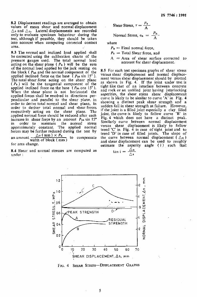
8.2 Displacement readings are averaged to obtain values of mean shear and normal displacement As and An. Lateral displacements are recorded only to evaluate specimen behaviour during the test, although if possible, they should be taken into account when computing corrected contact area. c’ 8.3 The normal and inclined load applied shall be corrected using the calibration charts of the pressure gauges used. The total normal load acting on the shear plane ( Pn ) will be the sum of the normal load applied by the jack resting on the block ( &a and the normal component of the applied inclined force on the base ( Psa sin 15” 1. The total shear force acting on the shear plane ( PS ) will be the tangential com$onent of the applied inclined force on the base ( Pm coa 15” ). When the shear plane is not horizontal the applied forces shall be resolved in directions per- pendicular and parallel to the shear plane, in order to derive total normal and shear plane, in order to deriver total normal and shear forces respectively acting on the shear plane. The applied normal force should be reduced after each iucrease in shear force by an amount Pm sin 15’ in order to maintain the normal stress approximately constant. The applied normal forces, may be further reduced during the test by
an amount *’ ‘mm ) x Pn - width of block ( mm )
to compensate
for area change.
8.4 Shear and normal stresses are computed as under :
Shear Stress, 7 = $
Pn Normal Stress, on = --A--
where Pn = Final normal force, PS = Total Shear force, and
A = Area of shear surface corrected to account for shear displacement.
8.5 For each test specimen graphs of shear stress versus shear displacement and normal displace- ment versus shear displacement should by plotted as shown in Fig. 4. If the joint under test is tight like that of an interfa’ce between concrete and rock or an unfilled joint having interlocking asperities, the shear stress shear displacement curve is likely to be similar to curve ‘A’ in Fig. 4 showing a distinct peak shear strength and a sudden fall in shear strength at failure. However, if the joint is a filled joint especially a clay filled joint, the curve is likely to follow curve ‘B’ in Fig. 4 which does not have a distinct peak. Similarly curve between normal displacement versus shear displacement is likely to follow trend ‘C’ in Fig. 4 in case of tight joint and to trend ‘D’ in case of filled joints. The slope of the curve between normal displacement ( An)
and shear displacement can be used to roughly estimate the asperity angle ( i ) such that
An tan i = - aa
/RESIDUAL --1
“0 10 20 30 LO 50 60 70 I
iHEAR DISPLACEMENT. As, mm
FIG. 4 SHEAR STRESS-DISPLACEMENT GRAPHS
5
IS 7746 : 1991
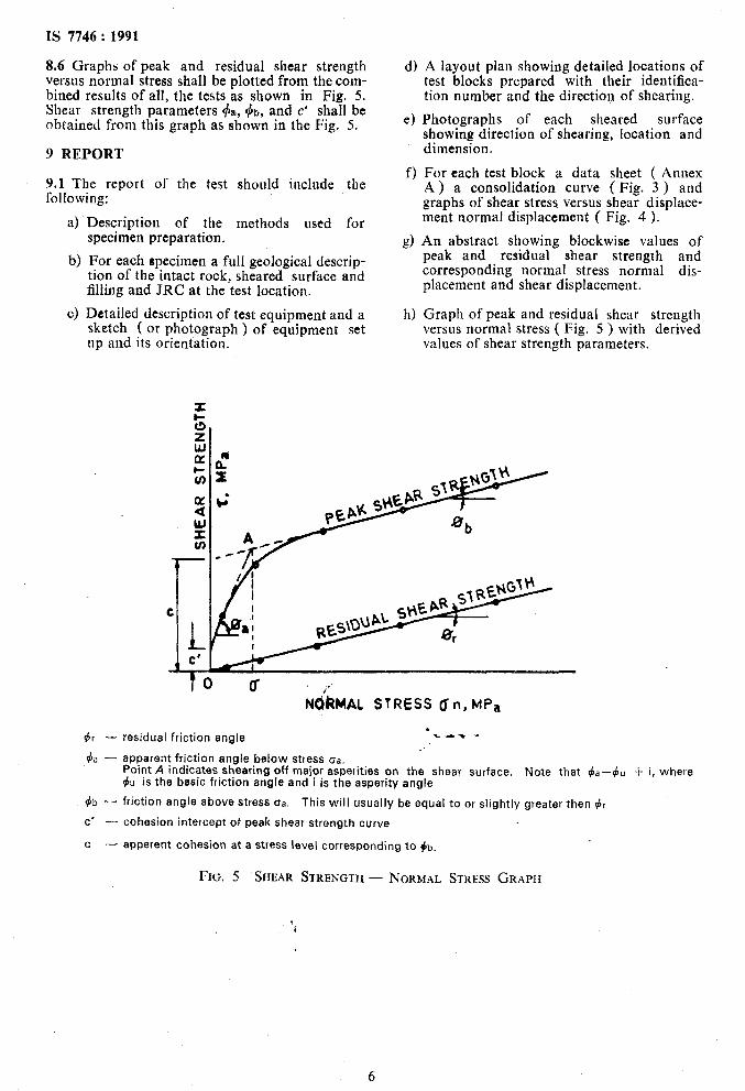
8.6 Graphs of peak and residual shear strength versus normal stress shall be plotted from the com- bined results of all, the tests as shown in Fig. 5. Shear strength parameters $a, +t, and c’ shall be obtained from this graph as shown in the Fig. 5.
9 REPORT
9.1 The report of the test should include the following:
a) Description of the methods used for specimen preparation.
b) For each specimen a full geological descrip- tion of the intact rock, sheared surface and filling and JRC at the test location.
c) Detailed description of test equipment and a sketch ( or photograph ) of equipment set up and its orientation.
d) A layout plan showing detailed locations of test blocks prepared with their identifica-
e)
f)
d
h)
tion number anh the direction of shearing.
Photographs of each sheared surface showing direction of shearing, location and dimension.
For each test block a data sheet ( Annex A ) a consolidation curve ( Fig. 3 ) and graphs of shear stress versus shear displace- ment normal displacement ( Fig. 4 ).
An abstract showing blockwise values of peak and residual shear strength and corresponding normal stress normal dis- placement and shear displacement.
Graph of peak and residual shear strength versus normal stress ( Fig. 5 ) with derived values of shear strength parameters.
f&?MAL STRESS U n, MPa
r’
dr - residual friction angle !-c-T -
& - apparent friction angle below stress oa. Point A indicates sheering off major asperities on the shear surface. Note that +a--)~ -I- i, where 4~ is the basic friction angle and i is the asperity angle
(bb - friction angle above stress oa. This will usually be equal to or slightly greater then $r
C’ - cohesion intercept of peak shear strength curve
C - apperent cohesion at a stress level corresponding to )b.
FIG. 5 SHEAR STRENGTH- NORMAL STRESS GRAPH
6
Standard Mark
The use of the Standard Mark is governed by the provisions of the Br~eau Q/” Ztuliurl Stmtlurtls Act, lY86 and the Rules and Regulations made thereunder. The Standard Mark on products covered by an Indian Standard conveys the assurance that they have been produced to comply with the requirements of that standard under a well defined system of inspection, testing and quality control which is devised and supervised by RIS and operated by the producer. Standard marked products are also continuously checked by BIS for conformity to that standard as a further safeguard. Details of conditions under which a licence for the use of the Standard Mark may be granted to manufacturers or producers may be obtained from the Bureau of Indian Standards.
Bureau of Indian Staudards ..; )
BIS is a statutory institutio~established under the Bureau 0J Indian Standards Act, 19$6&b promote harmonious devel@nent OT the activities of standardization, marking and quality certifi%& of goods and attending to&n.nected matters in the country.
_ i Copyright, .-. 1:. ‘.“1 : ‘- ‘, ’
BIS has the copyright of all its publtitions No part of these publications may be reproduced in any form without the prior perm&on in writing of BIS. This does not preclude the free use, in the course of implementing the standard, of ,necessary details. such as symbols and sizes, type or grade designations. Enquiries relating to copyright be addressed to the Director ( Publications ), BIS.
Revision of Indian Standards
Indian Standards are reviewed periodically and revised, when necessary and amendments, if any, are issued from time to time. Users of Indian Standards should ascertain that they are in possession of the latest amendments or edition. Comments on this Indian Standard may be sent to BIS giving the following reference :