Disclosure to Promote the Right To Information Whereas the Parliament of India has set out to provide a practical regime of right to information for citizens to secure access to information under the control of public authorities, in order to promote transparency and accountability in the working of every public authority, and whereas the attached publication of the Bureau of Indian Standards is of particular interest to the public, particularly disadvantaged communities and those engaged in the pursuit of education and knowledge, the attached public safety standard is made available to promote the timely dissemination of this information in an accurate manner to the public. इंटरनेट मानक “!ान $ एक न’ भारत का +नम-ण” Satyanarayan Gangaram Pitroda “Invent a New India Using Knowledge” “प0रा1 को छोड न’ 5 तरफ” Jawaharlal Nehru “Step Out From the Old to the New” “जान1 का अ+धकार, जी1 का अ+धकार” Mazdoor Kisan Shakti Sangathan “The Right to Information, The Right to Live” “!ान एक ऐसा खजाना > जो कभी च0राया नहB जा सकता ह ै” Bhartṛhari—Nītiśatakam “Knowledge is such a treasure which cannot be stolen” IS 851 (1978): Specification for Synthetic Resin Adhesives For Construction Work (Non-Structural) in Wood [CED 20: Wood and other Lignocellulosic products]
Transcript
Disclosure to Promote the Right To Information
Whereas the Parliament of India has set out to provide a practical regime of right to information for citizens to secure access to information under the control of public authorities, in order to promote transparency and accountability in the working of every public authority, and whereas the attached publication of the Bureau of Indian Standards is of particular interest to the public, particularly disadvantaged communities and those engaged in the pursuit of education and knowledge, the attached public safety standard is made available to promote the timely dissemination of this information in an accurate manner to the public.
इंटरनेट मानक
“!ान $ एक न' भारत का +नम-ण”Satyanarayan Gangaram Pitroda
“Invent a New India Using Knowledge”
“प0रा1 को छोड न' 5 तरफ”Jawaharlal Nehru
“Step Out From the Old to the New”
“जान1 का अ+धकार, जी1 का अ+धकार”Mazdoor Kisan Shakti Sangathan
“The Right to Information, The Right to Live”
“!ान एक ऐसा खजाना > जो कभी च0राया नहB जा सकता है”Bhartṛhari—Nītiśatakam
“Knowledge is such a treasure which cannot be stolen”
“Invent a New India Using Knowledge”
है”ह”ह
IS 851 (1978): Specification for Synthetic Resin AdhesivesFor Construction Work (Non-Structural) in Wood [CED 20:Wood and other Lignocellulosic products]
(11'
...... 'OJenZeo<0
IS: 851 -1978(Reaffirmed 20()S)
r~EA~ ~ fR~•• t.:\
Indian Standard •SPECIFICATION FOR SYNTHETIC
RESIN ADHESIVES FOR CONSTRUCTIONWORK (NON-STRUCTURAL) IN WOOD
BUREAU OF INDIAN STANDARDSMANAK BHAVAN, 9 BAHADUR SHAH ZAFARMARG
NEW DELHI 110002
Gr 6 September 1978
IS : 851 • 1978
Indian StandardSPECIFICATION FOR SYNTHETIC
RESIN ADHESIVES FOR CONSTRUCTIONWORK (NON-STRUCTURAL) IN WOOD
( First Revision)
Wood Products Sectional Committee, BDC 20
Chairman
SHRI A. C. SEKHAR
Representing
Forest Research Institute & Colleges (TimberMechanics Branch), Dehra Dun
Members
Ministry of Railways
Indian Tea Association, CalcuttaDirectorate General of Civil Aviation, New DelhiFederation of Indian Plywood & Panel Industry,
New DelhiSHRI M. R. MOTAYED (Alternate)
SImI M. A. ISLAM Forest Department, Government of Assam, DispurDR JOSEPHGEORGE Indian Plywood Industries Research Institute,
Bangalore
ASfHSTANT DIRECTOR (SPECIFICA-'HON). RDSO, LUCKNOW
SHRI]. BAINSHRI P. R. CHANDRASEKHARSHRI L. N. DoKANIA
DR V. J. VICTOR ( Alternate)SHRI A. K. KADERKUTTYSHRI K. S. LAULY
SHRI THOMAS PAUL (Alternate)SIIRI G. R. MAVINKURVA
CHIEF CONSERVATOR OFFORESTS (GEN ) (Alternate)
SHRI P. V. MEHTA
LT-COL S. A. MOHILESHRI B. B. MEHTA (Alternate)
SHRI M. R. MOTAYED
SHRI S. K. DUTTA ( Alternate)
The Western India Plywoods Ltd, BaliapatamThe South India Plywood Manufacturers' Associa
tion, Calicut
Forest Department, Government of Karnataka,Bangalore
Directorate General of Technical Development, NewDelhi
Ministry of Defence ( R&D)
Plywood Manufacturers' Association of West Bengal,Calcutta
( Continuedon pagl 2 )
@ Copyright 1978BOREAlJ OF INDIAN STANDARDS
This publication is protected under the Indian COP.JIright Act (XIV of 1957) andreproduction in whole or in part by any means except with written permission of thepublisher shalIbe deemed to be an infringement of copyright under the said Act.
IS I 851 • 1978
Representing
capacity (C-59 lnderpllli, New Delhi
(Continuedfrom pagtl1)
Membns
DR A. N. NAYER
SaRI D. E. NEALE
DR R. S. RATRASHRI P. R. RIJSINGHANI
MAJ M. GOSWAMI (Alterrlllte)SaRI SHARAN SINGH
DR S. M. SINGH
In personaluoou )
United Planters' Association of Southern India,Cochin
National Buildings Organization, New DelhiEngineer-in-Chief's Branch, Army Headquarters
Directorate General of Supplies & Disposals, NewDelhi
Central Building Research Institute ( CSIR ),Roorkee
SaRI ARJUN DAB ( Alternate)SUPERINTENDING SURVEYOR OF Central Public Works Department, New Delhi
WORKS (II)SlIRI H. THOMSON Sitapur Plywood Manufacturers Ltd, Sitapur
SHRI G. W. M. WIIITTLE ( Alternate)SHRI D. V. VERMA ·Ministry of Defence (DGI)
SHRI NmMAL SINGH ( Alternate)SHRI D. AJITHA SIMHA, Director General, lSI ( Ex-officio M,mber)
Director ( Civ Engg )
Secretary
SHRIj. R. MEHTA
Deputy Director (Civ Engg ) , lSI
Adhesives for Wood and Wood Products Subcommittee, BDC 20: 4
Convener
DR R. C. GUPTA
Members
Forest Research Institute & Colleges, Dehra Dun
Doshi Brothers & Co, Anand
Ministry of Defence (R & D )
Hoechst Dyes & Chemicals Ltd, Bombay
Ciba Geigy of India Ltd, BombayNational Test House, Calcutta
SURI B. M. BANE,RJEESHRI V. B. TANDON ( Alternate)
SHRI P. K. BANERJISHRI F. B. KAPADIA (Alternate)
SHRI C. S. BHATNAGARDR D. K. DAB
SHRI A. GHOSH (Alternate)S~RI R. V. Dosirr
SHRI C. V. DOSH! ( Allernale")SHRr S. HARIDA$DR JOSEPH GEORGE
Shaw Wallace & Company Limited, CalcuttaIndian Plywood Industries Research Institute,
llangaloreSHRI S. S. ZOOLAOUIJ ( Alternate)
DR R. N. KUMAR The Western India Plywood Ltd, BaliapatamSHRI K. S. LAULY The South Indian Plywood Manufacturers' Associa-
tion, CalicutSHRr A. K. RAMACHANDRA ( Alternate )
( Continued onpage 21)
2
Add the words' Vallapine orMakai' after the word' canarium spp. '
AMENDMENT NO. 1 DECEMBER 1987TO
IS :851- 1978 SPECIFICATION FOR SYNTHETICRESIN ADHESIVES FOR CONSTRUCTIONWORK ( NON·STRUCTURAL ) IN WOOD
( FirBt Re"i.ion)
( Page 9, clause 5.6.1, line 5 ) - Substitute' 4 of IS : 1734 (Part 7 )1983* 'for 'Appendix H ',
( Page 9, clause 5.6.2, line 5 ) - Substitute '4 of IS : 1734 (Part 7)-1983* 'for' Appendix H '.
( Page 11, clause a-r.r, line I) 1( Page 12, clause c-ia, line 1 )
( Page 17, Clause r-r.i, line 1 )
( Page 20, Appendix H ) - Delete .
• Methods of test for plywood (second revision ).
(BDO 20)
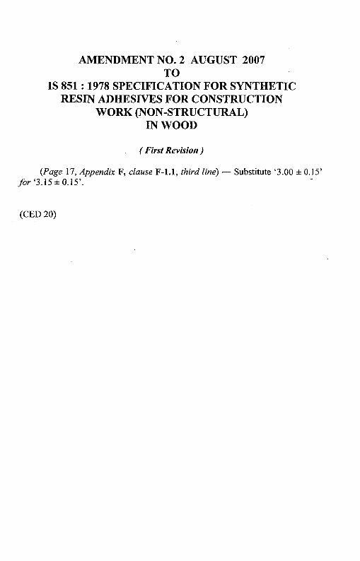
AMENDMENT NO.2 AUGUST 2007TO
IS 851 : 1978 SPECIFICATION FOR SYNTHETICRESIN ADHESIVES FOR CONSTRUCTION
SPECIFICATION FOR SYNTHETICRESIN ADHESIVES FOR CONSTRUCTIONWORK (NON-STRUCTURAL) IN WOOD
( First Revision)
o. FOR E W 0 R D
0.1 This Indian Standard ( First Revision) was adopted by theIndian Standards Institution on 20 February 1978, after the draft finalizedby the Wood Products Sectional Committee had been approved by theCivil Engineering Division Council.
0.2 Adhesives form one of the most important raw materials used in theplywood industry and wood work and joinery industry. The selection ofthe adhesive and its correct use are important factors controlling thequality of the plywood or the joinery work produced. In the context ofthis background of the industry, it has been found necessary to lay downstandards governing the quality ofthe raw materials and the performanceexpected from the prepared glues.
0.3 The preparation of the. adhesive and its correct use are other importantaspects. Therefore, for the information of the users, the manufacturersshall furnish all the relevant information for the use of these adhesives inthe manner indicated in Appendix A.
0.4 This standard covers both phenolic as well as aminoplastic syntheticresin adhesives. The phenolic resin adhesives are normally classified asBWP and BWR grade. The joints made with this type of adhesives arehighly resistant to weather, micro-organisms, cold and boiling water, steamor dry heat. The aminoplastic resin adhesives generally classified asWWR or CWR grade adhesives of urea formaldehyde base, deterioraterapidly on full exposure to weathering. These are, therefore, not recommended where high level of moisture is experienced. However, UF resinsfortified either with melamine, phenol or resorcinol and urea formaldehydemelamine formaldehyde mixes show much improved performance over UFresins.
3
IS I 851. 1978
0.5 This standard was first published in 1957. In this first revision, threetypes of adhesives covered in the earlier version have been re-designated andan additional type ( BWR ) has been included. The definition requirementsand methods of tests as applicable to these types have .been modifiedin light of experience.
0.6 This standard contains clauses 5.3.1 and 5.3.2 which permit the userto use his option for selection to suit his requirements at the time ofplacingorders,
0.7 In the formulation of this standard due weightage has been given tointernational co-ordination among the standards and practices prevailingin different countries in addition to relating it to the practices in the fieldin this country.
0.8 For the purpose of deciding whether a particular requirement of thisstandard is complied with, the final value, observed or calculated, expressing the result of a test or analysis, shall be rounded off in accordance withIS: 2-1960*. The number of significant places retained in the rounded offvalue should be the same as that of the specified value in this standard.
1. SCOPE
1.1 This standard prescribes the requirements for synthetic resin adhesivessuitable for wood work ( non-structural) and joinery.
2., TERMINOLOGY
2.1 For the purpose of this standard, the definitions given in IS: 707-1976tand the following shall apply.
2.1.1 Assembly Time
2.1.1.1 Open assembly time - The time elapsing between the applicationof the adhesive and assembly ofjoint components.
2.1.1.2 Closed assembly time - The time elapsing between assembly ofthe joint components and the application of pressure.
2.1.2 Adhesive
2.1.2.1 Closedcontact adhesive - A non-gap-filling adhesive suitable foruse only in those joints where the surfaces to be joined may be broughtinto close contact by means of adequate pressure, and where glue lineexceeding 0'12 mm may be-avoided with certainty.
*Rules for rounding off numerical values ( revised). '.tGlossary of terms applicable to timber technology and utilization (second revision ).
4
IS I 851 • 1978
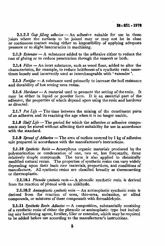
2.1.2.2 Gap fillzng adhesioe - An adhesive suitable for use in thosejoints where the surfaces to be joined mayor may not be in closeor continuous contact owing either to impossibility of applying adequatepressure or to slight inaccuracies in machining.
2.1.3 Extender- A substance added to the adhesive either to reduce thecost of gluing or to reduce penetration through the veneers or both.
2.1.4 Filler- An inert substance, such as wood flour, added to alter thecharacteristics, for example, to reduce brittlenessofa synthetic resin sometimes loosely and incorrectly used as interchangeable with C extender '.
2.1.5 Fortifier - A substance used primarily to increase the boil resistanceand durability of hot setting urea resins.
2.1.6 Hardener - A material used to promote the setting of the resin. Itmay be either in liquid or powder form. It is an essential part of theadhesive, the properties of which depend upon using the resin and hardeneras directed.
2.1.7 Pot Life~ The time between the mixing of the constituent partsof an adhesive and its reaching the age when it is no longer usable.
2.1.8 Shelf Life - The period for which the adhesive or adhesive components may be stored without affecting their suitability for use in accordancewith the standard.
2.1.9 Spread of Adhesive - The area of surface covered by 1 kg of adhesivemix prepared in accordance with the manufacturer's instructions.
2.1.10 Synthetic Resin - Amorphous organic materials produced by thepolymerization or condensation of one, two or, less frequently, threerelatively simple compounds. The term is also applied to chemicallymodified natural resins. The properties of synthetic resins can vary widelydepending upon their basic raw materials, proportions, and conditions ofmanufacture. All synthetic resins are classified broadly as thermosettingor thermoplastic.
,2.1.10.1 Phenolic synthetic resin -.:.A phenolic synthetic resin: is derivedfrom the reaction of phenol with an aldehyde.
2.1.10.2 Aminoplasti« synthetic resin - An aminoplastic synthetic resin isderived from the reaction of urea, thio-urea, melamine, or alliedcompounds, or mixtures of these compounds with formaldehyde.
2.1.11 Synthetic Resin Adhesive - A composition, substantially consistingof a synthetic resin of either the phenolic or aminoplastic type but including any hardening agent, fortifier, filler or extender, which may be requiredto be added before use according to the manufacturer's instructions.
5
IS : 851 • 1978
3. TYPES
3.1 Depending upon their degree of resistance to water and microorganisms, synthetic resin adhesives for wood shall be of the following fourtypes:
Boiling Water Proof BWPBoiling Water Resistance BWRWarm Watcr Resistance WWRCold Water Resistance CWR·
3.1.1 Gap-filling and close contact adhesives of the four types shall bedistinguished by the following symbols:
Type Symbol,.- .A. ~
Gap-Filling Close ContactAdhesive Adhesive
Boiling Water ProofBoiling Watcr ResistanceWarm Watcl' ResistanceCold Water Resistance
BWP/GFBWR/GFWWR/GFCWR/GF
BWP/CCBWR/CCWWR/CCCWR{CC
4. KEEPING QUALITIES
4.1 The adhesives shall comply with the requirements specified under 5after the resin and hardener have been stored in the original closed containers according to the manufacturer's instructions and up to the daterecommended by the manufacturer.
5. TESTS
5.1 Sampling - A representative sample shall be drawn from each batchof adhesives. Such samples shall, in each case, be tested separately, andnot be bulked with other samples or otherwise averaged.
5.2 Veneers for Test Pieces - Veneers used in the preparation of testpieces shall comply with the requirements specified in Appendix B.
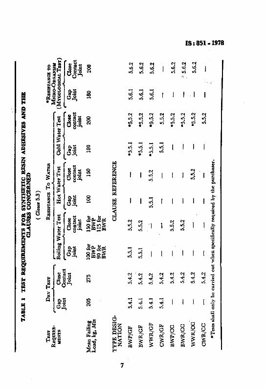
5.3 Test Requirements - The test requirements for each type ofadhesive shall be as given in Table 1. The gap-filling group shall betested with both gap joints and close-contact joints, but the close-contactgroup shall be tested with close-contact joints only.
5.3.1 Routine test for each type of adhesive shall be the dry testes) andthe wet test(s) at the temperature appropriate to its type. However, if sorequired by the purchaser, the adhesives of the BWP, BWR and WWR typesshall also be required to satisfy the requirements of the cold water test.
6
TA
BL
E1
TE
ST
RE
Q.1
1IR
EM
EN
TS
FO
RS
YN
TH
ET
ICR
ES
INA
DH
ES
IVE
SA
ND
TH
EC
LA
US
ES
CO
NC
ER
NE
D
(C
ltuU
e5.
3)
TE
STD
RY
TE
STRE
l!IlS
TAN
CET
oW
ATE
R-R
ESIS
TAN
CE
TORE
Q.U
lRB-
,.--
_--
A.
•.A
--
MIC
RO
-OR
GA
NIS
MK
ENTS
Gap
Clo
seB
oilin
gW
ater
Tes
tH
ot
Wat
erT
est
Col
dW
ater
Tes
t(M
YCO
LOG
ICA
LT
BaT
)jo
int
Con
tact
r....
•r-----A
.--
....
...
....._-...
...•
.jo
int
Gap
Clo
seG
apC
lose
Gap
Clo
seG
apC
lose
join
tco
ntac
tjo
int
cont
act
join
tco
ntac
tjo
int
Con
tact
join
tjo
int
join
tjo
int
Mea
nF
aili
ng20
527
510
0fo
r15
0fo
r10
015
018
020
018
020
0L
oad
,kg
,Min
BW
PB
WP
90fo
r11
5fo
rB
WR
BW
R
TY
PE
DE
SIG
-C
LA
US
ER
EF
ER
EN
CE
~N
AT
ION
BW
P/G
F5.
4.1
5.4.
25.
5.1
5.5.
2*5
.5.1
*5.•5
.25.
6.1
5.6.
2
BW
R/G
F5.
4.1
5.4.
25.
5.1
5.5.
2*5
.5.1
*5.5
.25.
6.1
5.6.
2
WW
R/G
F5.
4.1
5.4.
25.
5.1
5.5.
2*5
.5.1
*5.5
.25.
6.1
5.6.
2
CW
R/G
F5.
4.1
5.4.
25.
5.1
5.5.
2
BW
P/C
C5.
4.2
5.5.
2*5
.5.2
5.6.
2
BW
R/C
C5.
4.2
5.5.
2*5
.5.2
'.5.
6.2
...W
WR
/CC
5.4.
25.
5.2
·5.5
.2C'I
J5.
6.2
00
CW
R/C
C5.
4.2
5.5.
2f: ... •
*Tes
tssh
all
only
beca
rrie
dou
tw
hen
spec
ific
ally
requ
ired
byth
epu
rcha
ser.
... i:
IS: 851 • 1918
5.3.2 When specifically required by the purchaser, adhesives of theBWP, BWR and WWR types shall satisfy the requirements of the mycological test as given under 5•.6.
5.4 Dry Strength
5.4.1 Gap Joints - The average failing load of a set of six test piecesprepared by the method specified in Appendix C conditioned appropriatelyas specified in Appendix D, and when pulled by the method described inAppendix E shall be not less than 205 kg for all types.
5.4.2 Close Contact Joints - The average failing load of a set of six testpieces prepared by the method described in Appendix F, conditionedappropriately as specified under Appendix D and when pulled in accordance with Appendix E shall be not less than 275 kg for all types.
5.5 Resistance to Water
5.5.1 Gap Joints - The average failing load for a set of six test piecesprepared by the method specified in Appendix C, conditioned appropriatelyas specified in Appendix D and when pulled in accordance withAppendix E after treatment in the manner specified in Appendix G forthe time and temperature given in Table 2 shall be not less than thecorresponding value indicated therein.
TABLE 2 RESISTANCE TO WATER (GAP JOINTS)
( Clauses 5.5.1 and G·I.I )
TYPE TEMPERATURE OF WATER IN TIME OF MEAN FAILINGWHICH TEST PIECES SHALL IMMERSION LOAD
.BE IMMERSED
(I) (2) (3) (4)
0°0 h kg
BWP 100 6 100( or at the boiling point
of water )BWR. do 3 90WWR J£)±2 3 100OWR At±2 16 to 24 180
5.5.2 Close-Contact Joints - The average failing load for a set of six testpieces prepared by the method specified in Appendix F, conditionedappropriately as specified in Appendix D, and when pulled by the methoddescribed in Appendix E, after treatment in accordance with Appendix Gfor the time and temperature given in Table 3 shall be not less than thecorresponding values indicated therein.
8
IS I 851 • 1978
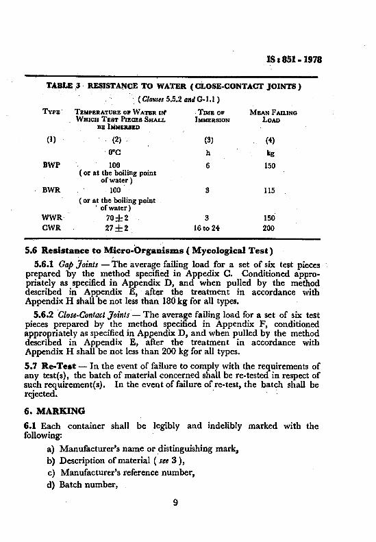
TABLE ,3 RE~ISTA~CE TO WATER (CLOSE.CONTACT JOINTS)
. (ClauSlS 5.5.2 andG-l.l)
TYPE TEMPERATURE OP WATER Ilt TIME OF MEAN FAILINGWHICH TEST PIECES SHALL IMMERSION LOAD
BE bWBR8BD
(I) (2) (S) (4)
. O°C h kg
BWP 100 6 150( or at the boiling point
of water )BWR 100 3 115
( or at the boiling point. of water)
WWR· 70±2 3 150'CWR 27±2 16 to 24 200
5.6 ResistaDce to Micro-Organisms ( Mycological Test). .
5.6.1 Gap Joints - The average failing load for a set of six test piecesprepared by the method specified in Appedix C. Conditioned appropriately as specified in Appendix D, and when pulled by the methoddescribed in Appendix E, after the treatment in accordance withAppendix H shall be not less than 180kg for all types.
5.6.2 'Close-Contact Joints - The average failing load for a set of six testpieces prepared by the method specified in Appendix F, conditionedappropriately as specified in Appendix D, and when pulled by the methoddescribed in Appendix E, after the treatment in accordance withAppendix H shall be not less than 200 kg for all types.
5.7 Re-Test - In the event of failure to comply with the requirements ofany test(s), the batch of material concerned shall be re-tested in respect ofsuch requirement(s). In the event of failure of re-test, the batch shall berejected. ..
6. MARKING
6.1 Each container shall be legibly and indelibly marked with thefollowing:
a) Manufacturer's name or distinguishing mark.b) Description of material (see 3),c) Manufacturer's reference number,d) Batch number,
9
IS: 851 ~ 1978
e) Date of manufacture, .
f) The date beyond which the adhesive or adhesive components shallnot be used when stored under. conditions recommended by themanufacturer,
g) Reference to the manufacturer's instructions for use, and.
h) The words' to be stored in a cool dry place '.
6.1.1 The product may also be marked with Standard Mark.
6.1.2 The use of the Standard Mark is governed by the provisions of the Bureauof Indian Standards Act, 1986 and the Rules and Regulations made thereunder.The details of conditions under which the licence for the use of Standard Markmay be granted to manufactures-or producers may be obtained from the Bureauof Indian Standards.
APPENDIX A
( Clause 0.3 )
INFORMATION TO BE FURNISHED BY THEMANUFACTURER REGARDING THE USE OF ADHESIVES
A-I. GUIDANCE REGARDING USE
A-I.I The manufacturer shall furnish written instructions detailing themanner in which each resin or recommended combination of resin(s),hardnerts), filler fortifiers and extenders shall be used. The instructionsshall give information in the manner indicated under A-I.2 to A-I.6, whereapplicable.
A-I.2 Storage Life of Adhesive or Adhesive .. Components - Themanufacturer shall specify the storage life of the adhesive components.
A-I.3 Preparation for Use - The preparation of resin, hardener, fortifier,filler and extender, method of mixing, recommended types of mixing,apparatus, and necessary precautions of any kind shall be stated.
10
IS, 851 .1978
A-I.4 Usable Life of Mixed Adhesive. 01' Pot Life - The maximumtime shall be stated during which the adhesive maintained at temperaturesof 15, 20, 25, 30, 40 and 45°C would remain fit for use so as to complywith the requirements of the specification.
A-I.S Methods of Use - Guidance on the following points shall begiven:
a) Range of moisture content of wood;
b) Preparation of wood surfaces;
c) Methods of application, such as single or double spread;
d) Normal amounts of spread for single glue line;
e) Maximum and minimum open and closed assembly times;
f) Recommended range of pressures in N/m? (kg/cm?);
g) Post-treatment of finished product; and
h) Cleaning of containers and test.
A-I.6 Setting Times and ConditioDs - The recommended range oftemperature to which the adhesive in any glue line may be subjected andalso the minimum and maximum times for which pressure shall bemaintained on unstressed joints at temperatures within the range shall bestated.
APPENDIX B
( Clauses 5.2 and F-l.l )
VENEERS FOR TEST PIECES
8-1. REQUIREMENTS
8-1.1 The Veneers shall be rotary-cut canarium spp. 3'00 ± 0'15 mm thickwith the growth rings approximately parallel to the face.
8-1.2 Veneers shall be smooth-cut on both faces, straight grained and freefrom all defects, at least over the area that will form the middle 50 mmlength of the test pieces, and may be slightly sanded. Elsewhere, theoccurrence of slight defects, such as small uplifts, small live knots and shortgrain, may be disregarded. The moisture content of the veneers shall be12'0 ± 2'5 percent for liquid adhesive and 12'0 ± 2'0 percent for filmadhesive, as may be recommended by the manufacturer.
11
as a851 - 1978
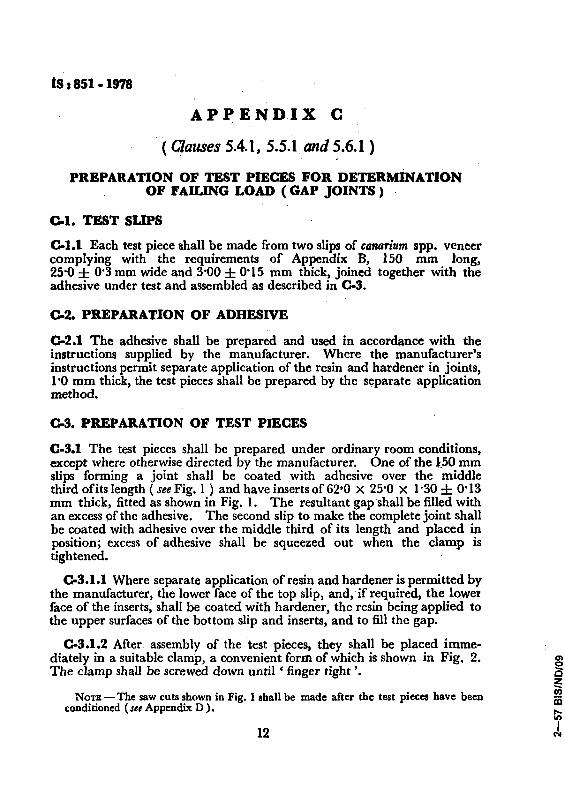
APPENDIX C
( Clauses 5.4.1. 5.5.1 and 5.6.1 )
PREPARATION OF TEST PIECES FOR DETERMINATIONOF FAILING LOAD (GAP JOINTS)
(]'1. TEST SLIPS
(]'1.1 Each test piece shall be made from two slips of canarium spp. veneercomplying with the requirements of Appendix B, 150 mm long,25'0 ± 0'3 mm wide and 3'00 ± 0'15 mm thick, joined together with theadhesive under test and assembled as described in 0-3.
(]'2. PREPARATION OF ADHESIVE
(].2.1 The adhesive shall be prepared and used in accordance with theinstructions supplied by the manufacturer. Where the manufacturer'sinstructions permit separate application of the resin and hardener in joints,1'0 mm thick, the test pieces shall be prepared by the separate applicationmethod.
os, PREPARATION OF TEST PIECES
C-3.1 The test pieces shall be prepared under ordinary room conditions,except where otherwise directed by the manufacturer. One of the l.50 mmslips forming a joint shall be coated with adhesive over the middlethird ofits length ( see Fig. I ) and have inserts of 62'0 X 25'0 X 1'30 ± 0'13mm thick, fitted as shown in Fig. 1. The resultant gap shall be filled withan excess of the adhesive. The second slip to make the complete joint shallbe coated with adhesive over the middle third of its length and placed inposition; excess of adhesive shall be squeezed out when the clamp istightened.
0-3.1.1 Where separate application of resin and hardener is permitted bythe manufacturer, the lower face of the top slip, and,ifrequired, the lowerface of the inserts, shall be coated with hardener, the resin being applied tothe upper surfaces of the bottom slip and inserts, and to fill the gap.
0-3.1.2 After assembly of the test pieces, they shall be placed immediately in a suitable clamp, a convenient form of which is shown in Fig, 2.The clamp shall be screwed down until ' finger tight'.
NOTE - The saw cuts shown in Fig. 1 shall be made after the test pieces have beenconditioned (see Appendix D).
12
ts: 851 .1978
_---------\50----------
25·0~ 0·3+Ot--....,~ /SAW CUT APPROXIMATELY3 mm WIDE
ADHESIVEJ
\·30!O·13 mmv!':NEER .
&00' 0·15 mmVENEER
All dimensions in millimetrcs.
FlO. I· GAP TEST PIECE SHOWING METHOD OF FITTING INSERTS
13
IS : 851 - 1978
~~-----
L--------- 190 --------
__------- 170 -------t
All dimensions in millimetre!.
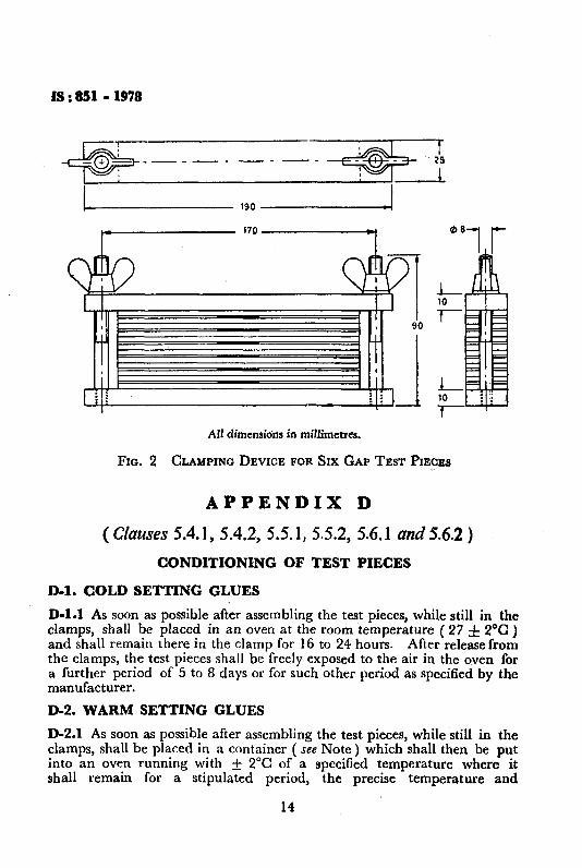
FIG. 2 CLAMPING DEVICE FOR SIX GAP TEST PIECES
APPENDIX D
( Clauses 5.4.1, 5.4.2, 5.5.1, 5.5.2, 5.6.1 and 5.6.2 )
CONDITIONING OF TEST PIECES
D-l. COLD SETTING GLUES
D-l.1 As soon as possible after assembling the test pieces, while still in theclamps, shall be placed in an oven at the room temperature ( 27 ± 2°C)and shall remain there in the clamp for 16 to 24 hours. After release fromthe clamps, the test pieces shall he freely exposed to the air in the oven fora further period of 5 to 8 days or for such other period as specified by themanufacturer.
D-2. WARM SETTING GLUES
D-2.1 As soon as possible after assembling the test pieces, while still in theclamps, shall be placed in a container ( see Note) which shall then be putinto an oven running with ± 2°C of a specified temperature where itshall remain for a stipulated period, the precise temperature and
14
IS I 851 - 1978
time being In accordance with the instructions of the manufacturer. Aftertreatment in the oven, and as soon as the container and the contents havecooled so that they can be handled conveniently, the test pieces shall beremoved from the clamps and stored at room temperature (27 ± 2°0) for16 to 26 hours prior to pulling.
NOTE - The purpose of the container is to prevent excessive loss of moisture from thetest pieces during the treatment at high temperatures. It shall, therefore, be made of areasonably impervious material and have a close-fitting lid. A small hole shall beprovided for the changes in volume of the air during the heating and cooling.
D-2.2 The manufacturer may prescribe and use any other method ofheating and conditioning the test piece, provided details of the process aremade available to the user.
E-O.l Due to the non-axial transmission of load through the prescribedtest pieces and the consequent tendency to bend during pulling, the strengthwhich the joints develop on test is influenced by the extent to which thebending is restrained. Testing machines vary widely in this respect, oneextreme being represented by the shot loading type of machine, in whichthe upper grips are suspended through two articulated joints from a leverfree to move longitudinally, while the other extreme is typified bythe standard high-capacity testing machine with substantial wedge grips ina massive head in which the ends of the test pieces are maintained rigidlyin line throughout the test.
E-0.2 At present there is insufficient knowledge about the influence of thevarious factors involved to enable them to be taken into account forpurposes of specifications; nor can any of the existing testing machines beregarded as sufficiently near the ideal to serve as a standard. Pending thedevelopment of a standard method of test, control is limited to therate at which the load is applied to the test piece, to the distance betweenthe grips, and to the accuracy with which the load is measured. The rateof loading mentioned in Method 2 under E-2.2 is designed to take intoaccount the slip experienced with wedge grips, particularly when testingjoints after soaking.
s-r, ACCURACY OF TESTING MACHINE
E-l.1 The test pieces shall be pulled in a testing machine capable ofmeasuring the breaking load with an accuracy of ± 1 percent.
15
IS : 851 - 1978
B-2. RATE QF LOADING
E-2.1 In testing machine provided with a means of controlling the rate ofincrease of load, the rate of increase of load shall be between 135 kg and270 kg/min.
E-2.2 In testing machines, provided with a means of controlling the rateof separation of the straining heads, one ofthe following two methods shallbe applicable:
Method 1
A device shall be provided, incorporating a pointer moving at constantspeed over a scale graduated so as to indicate a rate of increaseof load within the limits of E-2.1, with which the load indicatorof the testing machine shall be caused to move in unison by appropriate manipulation of the rate of strain control A scale having 45divisions to the full circle ( corresponding to the mean rate of loadingof 202'5 kg/min) placed behind the second hand of a clock, wouldbe a suitable device. The necessary limits of accuracy would bemaintained by keeping the pointers in agreement within ± 33percent.
Method 2
The straining rate shall be such that the time taken to pass from onequarter to the full specified minimum load shall be within the limitswhich would apply .under &2.1 (for example, in the case of aspecified minimum load of 90 kg, the time interval between 90/4 =22'5 kg load and 90 kg load, that is in increasing the load by 67'5 kgshould be between 67'5/135 and 67'5/270 minutes, which is between0'5 and 0'25 minutes ).
E-3. DISTANCE BETWEEN THE GRIPS
E-3.1 The distanc:e between the grips of the testing machine shall bebetween 65'0 and 70'0 mm in the case of gap joints and between 115 and120 mm in the case of close-contact joints.
E-4. COMPUTATION OF RESULTS
E-4.1 The average failing load for each test shall be computed from thecorresponding group of six test pieces.
16
(S: 851-1978
APPENDIX F
( Clauses 5.4.2, 5.5.2, 5.6.2 and B-1 )
PREPARATION OF TEST PIECES FOR DETERMINATION.OF FAILING LOAD (CLOSE-CONT·ACT JOINTS)
F-l. TEST SLIPS
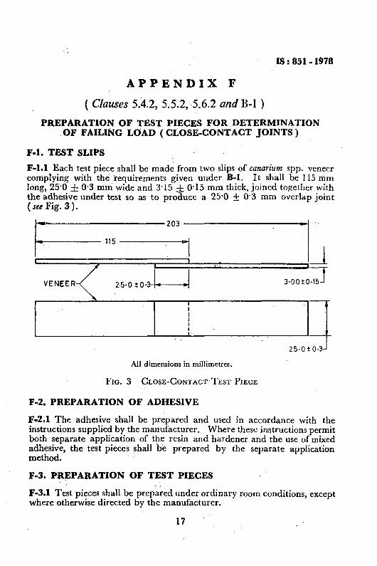
F-l.l Each test piece shall be made from two slips of conarium spp. veneercomplying with the requirements given under B-1. It shall be 115 mmlong, 25'0 ± 0'3 mm wide and 3'15 :i: 0'15 mm thick, joined together withthe adhesive under test so as to produce a 25'0 ± 0'3 mm overlap joint(see Fig. 3).
3'OO±O~
..,
•125·0 ±0.3J.....--•
r- 203 -----------
~-.--115---
L-----·----...,.---L.---:--.l----------25
- .0......'J
All dimensions in millimetres.
FIG. 3 CLOSE-CONTACT TEST PIECE
F-2. PREPARATION OF ADHESIVE
F-2.1 The adhesive shall be prepared and used in accordance with theinstructions supplied by the manufacturer. Whete these instructions permitboth separate application of the resin and hardener and the use of mixedadhesive, the test pieces shall be prepared by the separate applicationmethod.
F-3. PREPARATION OF TEST PIECES
F-3.1 Test pieces shall be prepared under ordinary room conditions, exceptwhere otherwise directed by the manufacturer.
17
ts :851 • 1978
F.3.2 The adhesive shall be applied uniformly to one of the two facesforming a joint or as prescribed by the manufacturer. The joints shall bemade between the smooth faces of the veneers. The slips forming a jointshall be placed in contact without rubbing, immediately the adhesive isapplied, or after such period as may be prescribed by the manufacturer.When the test pieces have been prepared, they shall be placed immediatelyin a suitable clamp, a convenient form of which is shown in Fig. 4.Sufficient pressure shall be applied to ensure good contact and generallyabout 50 kg is adequate. With the form of clamp shown in Fig. 4, thispressure may be obtained by screwing down until' finger tight'. Aconvenient jig for locating the clamp and its contents is shown in Fig. 5 .
20 mm THICKRUBBER
....--+-25
10 LIGHT.-, SPRINGS
1_.-64-~ I.TESTPIECE
All dimensions in millimetres,
FIG. 4 CLAMPING DEVICE FOR HOLDING SIX TEST PIECES
18
IS. 851 • 1978
k-~-25
6mm ECCENTRICITY
All dimensions in millimetres.
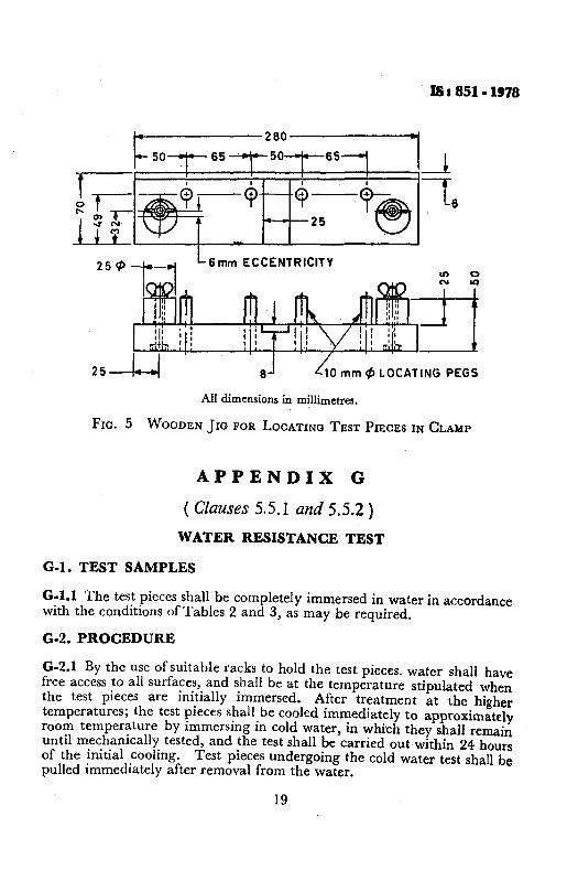
FIG. 5 WOODEN JIG FOR LOCATING TEST PIECES IN CLAMP
APPENDIX G
( Clauses 5.5.1 and 5.5.2)
WATER RESISTANCE TEST
o.i. TEST SAMPLES
G-l.l The test pieces shall be completely immersed in water in accordancewith the conditions of Tables 2 and 3, as may be required.
G-2. PROCEDURE
G-2.1 By the use of suitable racks to hold the test pieces. water shall havefree access to all surfaces, and shall be at the temperature stipulated whenthe test pieces are initially immersed. .After treatment at the highertemperatures; the test pieces shall be cooled immediately to approximatelyroom temperature by immersing in cold water, in which they shall remainuntil mechanically tested, and the test shall be carried out within 24 hoursof the initial cooling. Test pieces undergoing the cold water test shall bepulled immediately after removal from the water.
19
IS I 851 -1978
APPENDIX H
( Clauses 5.6.1 and 5.6.2 )
MYCOLOGICAL TEST
H-l. TEST
H..l.1 Fill a rectangular dish of enamelled iron, glass or porcelain toa depth of about 25 mm with saw dust of. non-durable timber like semul,previously moistened with a sufficient amount of an aqueous solution,containing 12 g of cane sugar per litre of water. The quantity of sugarsolution added shall just be enough to moisten completely 'the saw dustand shall be not. so much as can be squeezed out by hand pressure. Toattain this condition with dry saw dust, it is usually necessary to add threetimes its weight ofwater. The saw dust shall be loosely pressed in the dishand the test specimens shall be so placed and pressed over the saw dustthat the upper surfaces of the specimens are level with the surface of thesaw dust.
H-l.2 The dish shall then be covered with a sheet of glass and the edges ofthe dish sealed against the glass with a strip of material, such as modellingclay or plasticine so that the atmosphere round the sample shall remainsaturated. The dish and contents' shall be maintained at 27 ± IDC forthree weeks, after which the samples' shall be removed, washed in coldwater and pulled immediately.
20
BUREAU OF INDIAN STANDARDSHeadquarters:Manak Bhavan, 9 Bahadur Shah Zalar Marg, NEW DELHI 110002Telephones: 23230131 , 23233375, 23239402 Fax: 91+011 23239399,23239382E-Mail: [email protected] website: http://www.bis.org.in
Central Laboratory:Plot No. 20/9, Site IV, Sahibabad Industrial Area, SAHIBABAD 201010
Regional Offices:Central : Manak Bhavan, 9 Bahadur Shah Zalar Marg, NEW DELHI11 0002
"Eastern : 1/14CIT Scheme VII M, V.I.P.Road, Kankurgachi, KOLKATA 700054