Disclosure to Promote the Right To Information Whereas the Parliament of India has set out to provide a practical regime of right to information for citizens to secure access to information under the control of public authorities, in order to promote transparency and accountability in the working of every public authority, and whereas the attached publication of the Bureau of Indian Standards is of particular interest to the public, particularly disadvantaged communities and those engaged in the pursuit of education and knowledge, the attached public safety standard is made available to promote the timely dissemination of this information in an accurate manner to the public. इंटरनेट मानक “!ान $ एक न’ भारत का +नम-ण” Satyanarayan Gangaram Pitroda “Invent a New India Using Knowledge” “प0रा1 को छोड न’ 5 तरफ” Jawaharlal Nehru “Step Out From the Old to the New” “जान1 का अ+धकार, जी1 का अ+धकार” Mazdoor Kisan Shakti Sangathan “The Right to Information, The Right to Live” “!ान एक ऐसा खजाना > जो कभी च0राया नहB जा सकता ह ै” Bhartṛhari—Nītiśatakam “Knowledge is such a treasure which cannot be stolen” IS 9108 (1979): Liquid flow measurement in open channels using thin plate weirs [WRD 1: Hydrometry]
Transcript
Disclosure to Promote the Right To Information
Whereas the Parliament of India has set out to provide a practical regime of right to information for citizens to secure access to information under the control of public authorities, in order to promote transparency and accountability in the working of every public authority, and whereas the attached publication of the Bureau of Indian Standards is of particular interest to the public, particularly disadvantaged communities and those engaged in the pursuit of education and knowledge, the attached public safety standard is made available to promote the timely dissemination of this information in an accurate manner to the public.
इंटरनेट मानक
“!ान $ एक न' भारत का +नम-ण”Satyanarayan Gangaram Pitroda
“Invent a New India Using Knowledge”
“प0रा1 को छोड न' 5 तरफ”Jawaharlal Nehru
“Step Out From the Old to the New”
“जान1 का अ+धकार, जी1 का अ+धकार”Mazdoor Kisan Shakti Sangathan
“The Right to Information, The Right to Live”
“!ान एक ऐसा खजाना > जो कभी च0राया नहB जा सकता है”Bhartṛhari—Nītiśatakam
“Knowledge is such a treasure which cannot be stolen”
“Invent a New India Using Knowledge”
है”ह”ह
IS 9108 (1979): Liquid flow measurement in open channelsusing thin plate weirs [WRD 1: Hydrometry]
IS : 9108 - 1979
Indian Standard LIQUID FLOW MEASUREMENT IN OPEN CHANNELS USING THIN PLATE WEIRS
( First Reprint MAY 1998 )
UDC 532.57 : 681.121.873 : 532.543
0 Copyright 1980
BUREAU OF INDIAN STANDARDS MANAK BHAVAN, 9 BAHADUR SHAH ZAFAR MARG
NEW DELHI 110002
Gr 9 Mum-y 1980
ls : 9108 - 1979
Indian Standard LIQUID FLOW MEASUREMENT IN OPEN CHANNELS USING THIN PLATE WEIRS
S~nr S. BANERSI Indian National Committee for the International Hydrological Programme ( CSIR ), New Delhi
DR BEARAT SINQH University of Roorkee CHIEE ENGINEER ( BRIDQES ) Roads Wing, Ministry of Transport & Shipping CHIEF EN~INEEB ( DE~K+N & Land Reclamation, Irrigation & Power Research
RES~A~C~C ) Institute, Government of Punjab, Amritsar DX~ECTO~ ( LRIPRI ) ( Alternate )
CEXEB ENQINE~R ( F I & T ) Central Water Commission, New Delhi DIREQTOR ( CSMRS ) ( Altnnafr )
CHIEF ENQINEER ( INvnsTIaATIoN ) Irrigation Department, Government of Tamil Nadu, Madras
DIRECTOR ( INSTITUTE or+ HYDRAULICS & HYDROLOGY ) ( AllnMIc )
DIBECTOR Andhra Pradesh Engineering Research Labora- tories, Hyderabad
DIEROTOR Central Water & Power Research Station, Pune DB Z. S. TAR~PORE ( Al~natc )
DIRECTOB Irrigation Research Institute, Government of Uttar Pradesh, Roorkee
DU~ECTOR River Research Institute, Government of West
DEPUTY DIRECTOR ( HYDRAU- Bengal, Calcutta
LICS GROUP A ) ( Akrnatc ) l SHRI 0. P. Gino Ganga Basin Water Resources Organization
( Ministry of Agriculture & Irrigation ), New Delhi
( Conhued on pnge 2 )
@ C+yright 1980
BUREAU OF INDIAN STANDARDS
This publication is protected under the Indian Cobright Act ( XIV of 1057) and reproduction in whole or in part by any means except with written permission of the publirher shall he deemed to be an infringement of copyright under the said Act.
IS:9108 -1979
( Continuedfram page 1 )
Mmbns Representing
SHRI N. K. GHOSR National Instrument ( Private ) Ltd, Calcutta HYDRAULIC ENOINEER Bombay Municipal Corporation
SHRI T. M. KANTAWALA ( Alternate ) JOINT DIRECTOR R E s E A R c II Research, Designs & Standards Organization
( BRIDLES & FLOODS ) ( Ministry of Railways), Lucknow DEPUTY DIRECTOR ( BRIDLES
MEMBER, INDO-BANQLA DESH IOINT RIVERS COMMISSION f Alternate 1
DR R.-C. MALHOTRA SHRI R. H. MENDONSA
’ Indian’Institute of Technology, New Delhi All India Instrument Manufacturers & Dealers
Association, Bombay SHRI J. MENDONSA ( Alternate )
METEOnOLOoIST India Meteorolorrical Department. New Delhi PROPN.S. GOVINDA RAO In personal capacity ( 89*Diagonal Road, Visuervaru-
PROP N. S. LAKSHMANA RAO pnram, Bangalore 560004 )
Indian Institute of Science, Bangalore SECRETARY SHXI G. S. SHIV-ANA
Central Board of Irrigation & Power, New Delhi Public Works Department, Government of
Karnataka, Bangalore SHRI D. AJITHA SIMHA, Director General, IS1 ( Ex-oficio Member )
Director ( Civ Engg )
Secretary
SHRI K. RAoHAVENDnAN Deputy Director (Civ Engg), IS1
Notches, Weirs and Flumes Subcommittee, BDC 17 : 2
Convener
SHRI C. V. GOLE
Members
DR B.K. AGARWALA
Central Water Commission, New Delhi
National Physical Laboratory ( CSIR ), New Delhi
DR BHARAT SINaH University of Roorkeo CHIEF ENoINEER ( INVESTIoATION ) Irrination Denartment, Government of Tamil
“Nadu, Ma&as . DIRECTOR (INSTITUTE OF HYDRAULICS&HYDROLOGY), POONDI ( Alternate )
DIRECTOR Andhra Pradesh Engineering Research Labora- tory, Hyderabad
DIRECTOR Central Water & Power Research Station, Pune DR K. S. RAJAoOPALAN ( Alternate )
DIRECTOR Irrigation Department, Govrrntncnt of Uttar Pradesh, Lucknow
RESEARCH OFFICER, HYDRAULIC DIVISION ( Alternate )
( Continued on page 44 )
2
IS I 9108 - 1979
Indian Standard
LIQUID FLOW MEASUREMENT IN OPEN CHANNELS USING THIN PLATE WEIRS
0. FOREWORD
0.1 This Indian Standard was adopted by the Indian Standards Institution on 30 March 1979, after the draft finalized by the Fluid Flow Measurement Sectional Committee had been approved by the Civil Engineering Division Council.
0.2 Thin plate ( notch ) weirs offer a good means of gauging small flows ( for example in laboratories, small open channels, etc ) with a good degree of accuracy. However, very small changes in weir geometry, or flow and installation conditions would considerably affect the discharge coefficients and the accuracy, which will then necessitate periodic individual calibration. Therefore installation and maintenance of these weirs are also important.
0.3 In the formulation of this standard due weightage has been given to international coordination among the standards and practices prevailing in different countries in addition to relating it to the practices in the field in this country. This has been met by basing the standard on IS0 1438/I Water flow measurement in open channels using weirs and venturi flumes - Part I : Thin plate weirs, issued by the International Organization for Standardization.
0.4 This standard is one of the series of Indian Standards on instruments used in stream gauging. Other standards in the series are:
IS : 6059-1971 Recommendation for liquid flow measurement in open channels by weirs and flumes - weirs of finite crest width for free discharge
IS : 6062-1971 Method of measurement of flow of water in open channels using standing wave flume-fall
IS : 6063-1971 Method of measurement of flow of water in open channels using standing wave flume
IS : 6330-1971 Recommendation for liquid flow measurement in open channels by weirs and flumes- end depth method for estimation of flow in rectangular channels with a free overfall ( approximate method )
3
IS : 910% - 1979
IS : 9117-1979 Recommendation for liquid flow measurement in open channels by weirs and flumes-end depth method for estimation of flow in non-rectangular channels with a free over- fall ( approximate method )
0.5 In reporting the results of a test made in accordance with this standard, if the final value, observed or calculated, is to be rounded off, it shall be done in accordance with IS : 2-1960*.
1. SCOPE
1.1 This standard specifies methods for measurement of water flow in open channels using rectangular and triangular-notch ( V-notch ) thin- plate weirs. The flow conditions considered are limited to steady, free and fully ventilated discharge of clear water. Recommended discharge coefficients are applicable to water only in the approximate range of tem- peratures from 5 to 40°C. Using the coefficients for water temperatures several degrees outside this range will result in negligible error except at very small heads. Limitations of applicability related to weir and flow geometry are specified for the recommended formulae.
2. DEFINITIONS
2.1 For the purpose of this standard, the definitions given in IS : 1191- 1971t shall apply. Terms which have special significance in this standard are defined where they first occur.
3. UNITS OF MEASUREMENT
3.1 Units used in this standard are SI units.
4. PRINCIPLE
4.1 The discharge over thin-plate weirs is a function of the head on the weir, the size and shape of the discharge area, and an experimentally determined coefficient which takes into account the head on the weir, the geometrical properties of the weir and approach channel and physical properties of water and characteristics of flow.
5. INSTALLATION
5.1 General - General requirements of yeir installations are described in the following clauses. Special requirements of different types of weirs are described in clauses which deal with specific weirs ( see 8 and 9 ).
*Rules for rounding off numerical values (raised 1. tClosaary of terms and symbols used in connection with the measurement of liquid
flow with a free surface (jirs6 rcui.km ).
4
!S I 9108 - 1979
5.2 Selection of Site - The type of weir to be used for discharge measurement is determined in part by the nature of the proposed measur- ing site. Under some conditions of design and use, weirs shall be located in rectangular flumes or in weir boxes which simulate flow conditions in rectangular flumes. Under other conditions, weirs may be located in natural channels as well as flumes or weir boxes, with no significant difference in measurement accuracy. Specific site-related requirements of the installation are described in 5.3.
5.3 Installation Conditions
5.3.1 General - Weir discharge is critically influenced by the physical characteristics of the weir and the weir channel. Thin-plate weirs are especially dependent on installation features which control the velocity distribution in the approach channel and on the construction and maintenance of the weir crest in meticulous conformance with standard specifications.
5.3.2 Weir - Thin-plate weirs shall be vertical and perpendicular to the walls of the channel. The intersection of the weir plate with the walls and floor of the channel shall be watertight and firm, and the weir shall be capable of withstanding the maximum flow without distortion or damage.
Stated practical limits associated with different discharge formulae such as minimum width, minimum weir height, minimum head, and maximum values of I@ and b/B ( where h is the measured head, p is the height of crest relative to floor, b is measured width of the notch and B is the width of the approach channel ), are factors which influence both the selection of weir type and the installation.
5.3.3 Approach Channel - For the purposes of this standard the approach channel is that portion of the weir channel which extends upstream from the weir a distance not less than ten times the width of the nappe at maximum head at the weir. If the weir is located in a weir box, the length of the box shall be equal to the specified length of the approach channel.
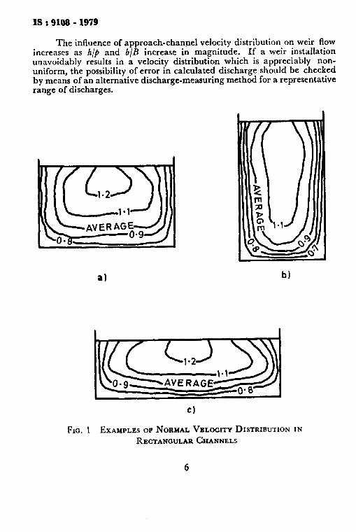
The flow in the approach channel shall be uniform and steady, with the velocity distribution approximating that in a channel of sufficient length to develop normal ( resistance-controlled) flow in smooth, straight channels. Figure 1 shows measured normal velocity distributions at the head measuring section in rectangular channels, upstream from the influence of a weir. Baffles and flow straighteners can be used to obtain normal velocity distribution, but their location with respect to the weir shall be not less than the minimum length prescribed f’or the approach channel.
5
IS r9108 -1979
The influence of approach-channel velocity distribution on weir flow increases as h/p and b/B increase in magnitude. If a weir installation unavoidably results in a velocity distribution which is appreciably non- uniform, the possibility of error in calculated discharge should be checked by means of an alternative discharge-measuring method for a representative range of discharges.
a)
cl
FIG. 1 EXAMPLES OF NORMAL VXLOCITY DISTRIBUTION IN RECTANCWLARCHANNELS
6
IS : 9108 - 1979
53.4 Downstream Channel - The shape and size of the channel down- stream from the weir is of no significance, but the level of the water in the downstream channel shall be a sufficient vertical distance below the crest to ensure free, fully ventilated discharges. Free ( non-submerged ) discharge is ensured when the discharge is independent of the downstream water level. Full ventilation is ensured when the air pressure on the lower surface of the nappe is fully atmospheric.
6. MEASUREMENT OF HEAD
6.1 Head Measuring Devices - In order to obtain discharge measure- ment accuracies specitied for the standard weirs, the head on the weir shall be measured with a laboratory-grade hook gauge, point gauge, manometer, or other gauge of equivalent accuracy. For a continuous record of head variations, precise Aoat gauges and servo-operated point gauges can be used. Staff and tape gauges can be used when less accurate measurements are acceptable,
6.2 Stilling Well - Generally, to avoid water-level variations caused by waves, turbulence or vibration, the headwater level should be measured in a stilling well. When surface velocities and disturbances in the approach channel are negligible, the headwater level can be measured directly (for example, by means of a point gauge mounted over the headwater surface ).
Stilling wells are connected to the approach channel by means of a suitable conduit, equipped if necessary with a throttle valve to damp oscillations. At the channel end of the conduit, the connection is made to floor or wall piezometers or a static tube located at the head-measurement section.
6.3 Head-Measurement Section - The head-measurement section shall be located a sufficient distance upstream from the weir to avoid the region of surface draw-down caused by the formation of the nappe. On the other hand, it shall be sufficiently close to the weir that the energy loss between the head-measurement section and the weir is negligible. For the weirs included in this standard the location of the head-measurement section will be satisfactory if it is at a distance equal to 4 to 5 times the maximum head ( 4 to 5 hmax) upstream from the weir.
If high velocities occur in the approach channel or if water-surface disturbances or irregularities occur at the head-measurement section because of high values of h/p or b/B, it may be necessary to install several pressure intakes to ensure that the head measured in the stilling well is the average of the heads at the several measurement points.
7
6.4 Head-Gauge Datum ( Gauge Zero ) - Accuracy of head measure- ments is critically dependent u on the determination of the head-gauge datum or gauge zero, which is B efined as the gauge reading corresponding to the level of the weir crest ( rectangular weirs ) or the level of the vertex of the notch ( triangular-notch weirs ). When necessary, the gauge zero shall be checked. Numerous acceptable methods of determining the gauge zero are in use. Typical methods are described in subsequent clauses dealing specifically with rectangular and triangular weirs ( see 8 and 9 ).
Because of surface tension, the gauge zero cannot be determined with sufficient accuracy by reading the head gauge with the water in the approach channel drawn down to the apparent crest ( or notch ) level.
7. MAINTENANCE
7.1 Maintenance of the weir and the.weir channel is necessary to ensure accurate measurements.
7.2 The approach channel shall be kept free of silt, vegetation and obstructions which might have deleterious effects on the flow conditions specified for the standard installation. The downstream channel shall be kept free of obstructions which might cause submergence or inhibit full ventilation of the nappe under all conditions of flow.
7.3 The weir plate shall be kept clean and firmly secured. In the process of cleaning, care shall be taken to avoid damage to the crest or notch, particularly the upstream edges and surfaces. Construction specifications for these most sensitive features should be reviewed before maintenance is undertaken.
7.4 Head-measurement piezometers, connecting conduits and the stilling well shall be cleaned and checked for leakage. The hook or point gauge, manometer, float or other instrument used to measure the head shall be checked periodically to ensure accuracy.
8. PROVlSIONS FOR VENTILATED FREE FLOW
8.1 Provisions for ventilation of the nappe should ensure that the pressure under the nappe surface is atmospheric. The tail water level should be low enough not to interfere with the ventilation or free discharge of the nappe.
NOTE -Free (unsubmerged ) flow is defined here as a flow which is indepen- dent of variations in tail water level. It is recommended that the tail water level should be preferably 0.1 m below the lowest point of the notch. It is recommended that the ventilating pipes, if any, should have an area of at least l/150 of the maximum water area in the notch.
8
t$ t 9108 - 1979
1p 10 2 mm
UPSTREAM FAC OF WEIR PLAT
DETAIL OF CREST AND
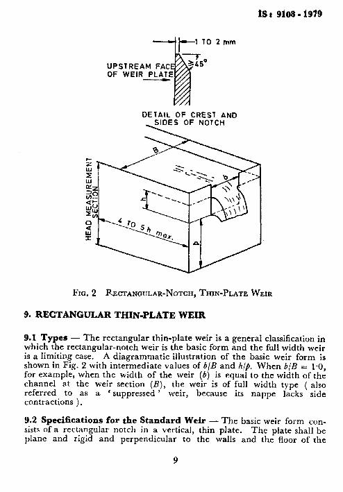
FIG. 2 RJICTANGULAR-NOTCH, THIN-PLATE WEIR
9. RECTANGULAR THIN-PLATE WEIR
9.1 Types - The rectangular thin-plate weir is a general classification in which the rectangular-notch weir is the basic form and the full width weir is a limiting case. A diagrammatic illustration of the basic weir form is shown in Fig. 2 with intermediate values of b/B and h/k. When b/B = l-0, for example, when the width of the weir (6) is equal to the width of the channel at the weir section (B), the weir is of full width type ( also referred to as a contractions ).
‘ suppressed ’ weir, because its nappe lacks side
9.2 Specifications for the Standard Weir - The basic weir form con- sists of a rectangular notch in a vertical, thin plate, The plate shall be plane and rigid and perpendicular to the walls and the floor of the
18 t 9199 - 1979
approach channel. The upstream face of the plate shall be smooth ( it shall be equivalent in surface finish to that of rolled sheet-metal ).
The vertical bisector of the notch shall be equidistant from the two walls of the channel. The crest surface of the notch shall be a horizontal, plane surface, which shall form a sharp edge at its intersection with the upstream face of the weir plate. The width of the crest surface, measured perpendicular to the face of the plate, shall be between 1 and 2 mm. The side surfaces of the notch shall be vertical, plane surfaces which shall make sharp edges at their intersection with the upstream face of the weir plate, For the limiting case of the full-width weir, the crest of the weir shall extend to the walls of the channel, which in the vicinity of the crest shall be plane and smooth at least up to the measuring section ( see also 9.3 ).
To ensure that the upstream edges of the crest and the sides of the notch are sharp, they shall be machined or filed, perpendicular to the upstream face of the weir plate, free of burrs or scratches and untouched by abrasive cloth or paper. The downstream edges of the notch shall be chamfered if the weir plate is thicker than the maximum allowable wjdth of the notch surface, not less than 45
The surface of the chamfer shall make an angle of’ with the crest and side surfaces of the notch
( see Fig. 2 ). The weir plate in the vicinity of the notch preferably shall be made of corrosion-resistant metal; but if it is not, all specified smooth surfaces and’sharp edges shall be kept coated with a thin, protective film ( for example, oil, wax, silicone ) applied with a soft cloth. 9.3 Specifications for Installation - The specifications stated in 5.3 shall apply. In general, the weir shall be located in a straight, horizontal, rectangular approach channel if possible. However, if the effective opening of the notch is so small in comparison with the area of the upstream channel that the approach velocity is negligible, the shape of the channel is not significant. In any case, the flow in the approach channel shall be uniform and steady, as specified in 5.3.3.
If the width of the weir is equal to the width of the channel at the weir section ( that is a full-width weir ), the sides of the channel upstream from the plane of the weir shall be vertical, plane, parallel and smooth (equivalent in surface finish to that of a neat cement ). The sides of the channel above the level of the crest of a full-width weir shall extend at least 0.3 hmax downstream from the plane of the weir. Fully ventilated nappe shall be ensured as specified in 5.3.4.
The approach channel floor shall be smooth, flat and horizontal when the height of the crest relative to the floor (p) is small and/or h/p is large. For rectangular weirs, the floor should be smooth, flat and horizon- tal, particularly, whenp is less than 0.05 m and/or hmax/P is greater than 1. Additional conditions are specified in connection with the recommended discharge formulae.
+ I
10
IS I 9108 - 1979
9.4 Specifications for Head Measurement
9.4.1 General - The conditions specified in 6.1, 6.2 and 6.3 shall apply without exception,
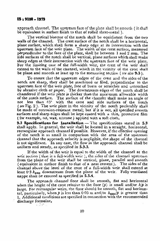
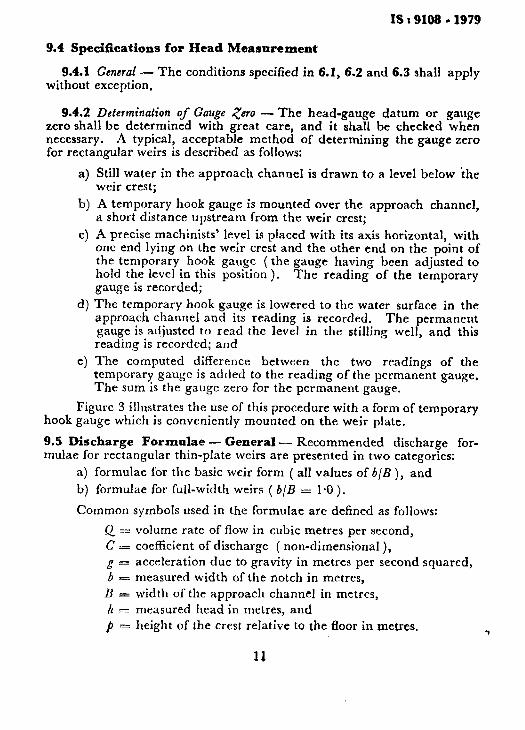
9.4.2 Determination of Gauge zero - The head-gauge datum or gauge zero shall be determined with great care, and it shall be checked when necessary. A typical, acceptable method of determining the gauge zero for rectangular weirs is described as follows:
a) Still water in the approach channel is drawn to a level below ‘the weir crest;
b) A temporary hook gauge is mounted over the approach channel, a short distance upstream from the weir crest;
c) A precise machinists’ level is placed with its axis horizontal, with one end lying on the weir crest and the other end on the point of the temporary hook gauge (the gauge having been adjusted to hold the level in this position ). gauge is recorded;
The reading of the temporary
d) The temporary hook gauge is lowered to the water surface in the approach channel and its reading is recorded. The permanent gauge is adjusted to read the level in the stilling well, and this reading is recorded; and
e) The computed difference between the two readings of the temporary gauge is added to the reading of the permanent gauge. The sum is the gauge zero for the permanent gauge.
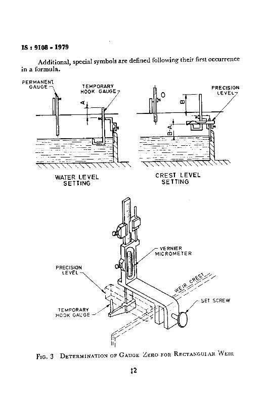
Figure 3 illustrates the use of this procedure with a form of temporary hook gauge which is conveniently mounted on the weir plate.
9.5 Discharge Formulae - General - Recommended discharge for- mulae for rectangular thin-plate weirs are presented in two categories:
a) formulae for the basic weir form ( all values of b/B ), and
b) formulae for full-width weirs ( b/B = 1.0).
Common symbols used in the formulae are defined as follows:
Q = volume rate of flow in cubic metres per second, C = coefficient of discharge ( non-dimensional ), g = acceleration due to gravity in metres per second squared, b = measured width of the notch in metres,
B width of the approach channel in metres, h r measured head in metres, and p = height of the crest relative to the floor in metres.
11
IS I 9108 - 1979
Additional, special symbols are defined following their first occurrence in a formula.
‘MANENI IAUGE TEMPORARY
HOOK GAUGE7 A PRECISION
CREST LEVEL SETTING
VERNIER MICROMETER
II i
FIG. 3 DETERMINATION OF GAUGE ZERO FOR RECTANGULAR WEIR
12
ts t 9108 - 1939
9.6 Formalae for the Basic Weir Form ( AU Values of 6/B)
9.6.1 Kindsvater-Carter Formula
The Kindsvater-Carter formula for the basic weir form is:
l . . (1)
where
Ce = coefficient of discharge,
b e = effective width, and h, = effective head.
The coefficient of discharge C, has been determined by experiment as a function of two variables from the formula:
The effective width and head are defined by the equations:
6, - b + kl, . . . (3) /I, = h + k,., ,.. (4)
in which kb and kh are experimentally determined quantities, in metres, which compensate for the combined effects of viscosity and surface tension.
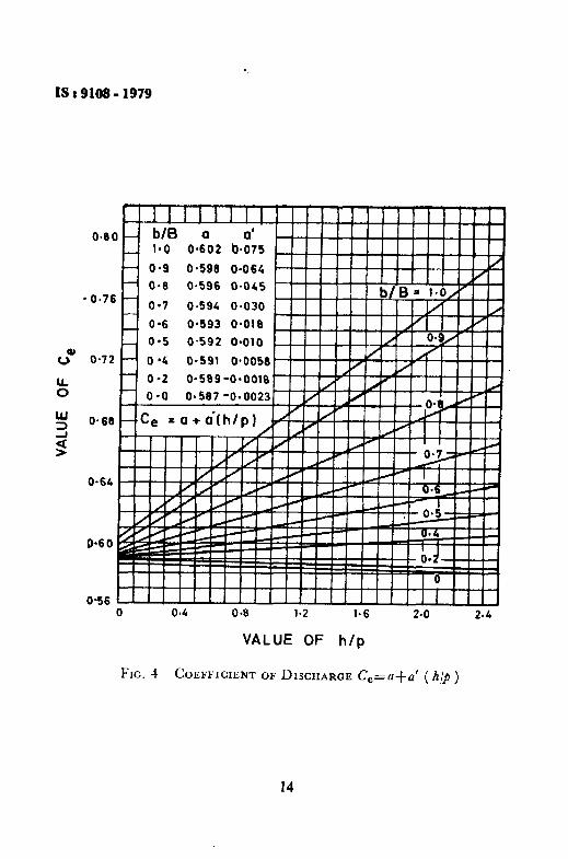
9.6.1.1 Evaluation of C,, kb and kb - Figure 4 shows experimentally determined values of C, as a function of h/k for representative values of b/B. Values of C, for intermediate values of b/B can be determined by interpolation.
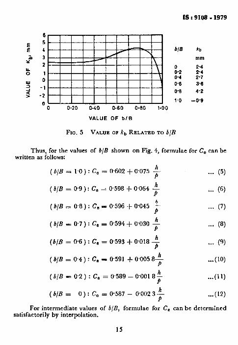
Figure 5 shows values of kb, which have been experimentally deter- mined as a function of b/B.
Experiments have shown that kh can be taken to have a constant value of O*OOl m for weirs constructed in strict conformance with recom- mended specifications.
9.6.1.2 Formulae for C, - For specific values of b/B the relationship between C, and h/p has been shown by experiment ( see Fig. 4 ) to be of the linear form:
C, = a + a’ ( >
+-
13
IS : 9108 - 1979
O*9 0.599 O-064
0.0 O-596 04&S
O-7 O-594 O*O30
O-6 Oei93 0~010
W
3
3 I I f I I I I
O-64
0.60
O-56 0 l-6 2-o 2.4
VALUE OF h/p
FIG. 4 COEFFICIENT OF DISCHARGE Ce=a+u’ ( h,/p )
14
IS : 9108 - 1979
6
5
4
3
2
1
0
-I
2
Cl I i i i.i i i i i i 1
b/B hb
mm
2.4 2'4 2'7 3.6
4.2
-0*9
0 0.20 0.40 0.60 0.80 l-00
VALUE OF b/B
Fxa. 5 VALUE OF kb RELATED TO b/B
Thus, for the values of b/B shown on Fig. 4, formulae for C, can be written as follows:
For intermediate values of b/B, formulae for C, can be determined satisfactorily by interpolation,
15
IS : 9108 - 1979
9.6.1.3 Practical limitations on h/k, h, b and p - Practical limits are placed on h/p because head measurement difficulties and errors result from surges and waves which occur in the approach channel at larger values of h/p. Limits are placed on h to avoid the ‘ clinging nappe ’ phenomenon which occurs at very low heads. Limits are placed on b because of uncertainties regarding the combined effects of viscosity and surface tension represented by the quantity of I+, at very small values of b. Limits are placed on p and B- b to avoid the instabilities which result from eddies that form in the corners between the channel boundaries and the weir when values ofp and B-b are small.
For conservative practice, limitations applicable to the use of the Kindsvater-Carter formula are:
a) h/p shall be not greater than 2.5;
b) h shall be not less than 0.03 m;
c) b shall be not less than 0.15 m;
d) p shall be not less than 0.10 m; and
e) either ( B - b )/2 = 0 ( full width weir) or ( B - b )/2 shall not be less than 0.10 m ( contracted weir ).
9.6.2 SIA* Formula The SIA formula for the basic weir form is:
Q = c -“,-m@-$b /,3/Z
in which
. ..(13)
* 0.003 615 - 0.003 0 C
’ = + - (
---
h -t_ 0.001 6 ‘I X
[I +0*5($)1(*)(-j 1.. (14)
Practical limitations applicable to the use of the SIA formula are:
a) h/j shall be not greater than 1.0;
b) b/B shall be not less than O-3;
c) h shall be not less than 0.025 B/b and not greater than 0.80 m; and
9.7 Formulae for Full-Width Weirs (6/8 = l*O) - In addition to formulae 5 and 15, which represent the limiting case of b/B = 1.0 in the Kindsvater-Carter and SIA formulae for weirs of the basic form, the following formulae are recommended for b/B = 1.0 only,
9.7.1 Rehbock Formula ( I929 ) - The Rehbock formula in the form proposed in 1929 is of the effective-head variety:
Q-G t&c b h,?@ . ..( 16)
in which
c B = O-602 + O-O%3 h/b . . . (17)
h n = h + 0.0012 . ..(18)
Practical limitations applicable to the use of the Rehbock formula are:
a) h/k shall be not greater than 1.0;
b) A shall be between O-03 and O-75 m;
c) b shall be not less than 0.30 m; and
d) p shall be not less than 0.10 m.
9.7.2 IMFT* Formula
The IMFT formula for full-width weir is:
. ..(19)
in which
C = 0.627 + 0.018 0 c 1 h + $gy
P ,.. (20)
in which, V, is the average velocity in the approach channel, V, = Q/As, where A,, is the area of the flow at the head-measurement section.
Because V, is a function of Q, it must be computed by successive approximations.
Practical limitations applicable to the use of the IMFT formula are:
a) h/b shall be not greater than 2.5;
b) h shall be not less than 0.03 m;
l Institut de Mhmique des Fluides de Toulouse.
17
IS : 9108 - 1979
c) b shall be not less than 0.20 m; and
d) ~3 shall be not less than 0.10 m.
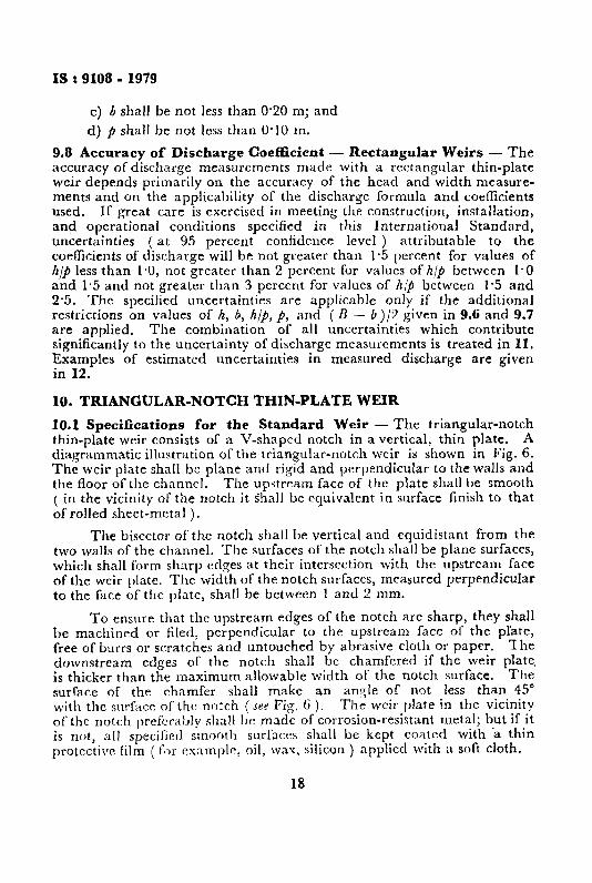
9.8 Accuracy of Discharge Coefficient - Rectangular Weirs - The accuracy of discharge measurements made with a rectangular thin-plate weir depends primarily on the accuracy of the head and width measure- ments and on the applicability of the discharge formula and coeflicients used. If great care is exercised in meeting the construction, installation, and operational conditions specified in this International Standard, uncertainties ( at 95 percent confidence level ) attributable to the coeficients of discharge will be not greater than 1.5 percent for values of /Z//J less than 1.0, not greater than 2 percent for values of h/p between I.0 and 1.5 and not greater than 3 percent for values of /z/p between 1.5 and 2.5. The specified uncertainties are applicable only if the additional restrictions on values of h, b, h/p, p, and ( B - b)/‘L given in 9.6 and 9.7 are applied. The combination of all uncertainties which contribute significantly to the uncertainty of discharge measurements is treated in II. Examples of estimated uncertainties in measured discharge are given in 12.
10. TRIANGULAR-NOTCH THIN-PLATE WEIR
10.1 Specifications for the Standard Weir - The triangular-notch thin-plate weir consists of a V-shaped notch in a vertical, thin plate. A diagrammatic illustration of the triangular-notch weir is shown in P’ig. 6. The weir plate shall be plane and rigid and perpendicular to the walls and the floor of the channel, The upstream face of the plate shall be smooth ( in the vicinity of the notch it Shall be equivalent in surface finish to that of rolled sheet-metal ).
The bisector of the notch shall be vertical and equidistant from the two walls of the channel. ‘I’he surfaces of the notch shalt be plane surfaces, which shall form sharp edges at their intersection with the upstream face of the weir plate. The width of the notch surfaces, measured perpendicular to the face of the plate, shall be between 1 and 2 mm.
To ensure that the upstream edges of the notch are sharp, they shall be machined or filed, perpendicular to the upstream face of the plate, free of burrs or scratches and untouched by abrasive cloth or paper. The downstream eclges of the notch shall be chamfered if the weir plate. is thicker than the maximum allowable width of the notch surface. The surface of the chamfer shall make an angle of not less than 45” with the surface of the notch ( ses Fig. 6 ). The weir plate in the vicinity of the notch prefiirably shall bc made of corrosion-resistant metal; but if it is not, all specified smootli surfaces shall be kept coatecl with ‘a thin protective film ( for example, oil, wax, silicon ) applied with a soft cloth.
18
IS : 9108 - 1979
UPSTREAM FAC OF WEIR PLATE
DETAIL OF SIDES OF NOTCH
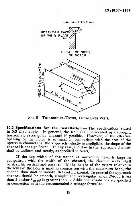
Fm. 6 TRIANGULAR-NOTCH, THIN-PLATE WEIR
10.2 Specifications for the Installation - The specifications stated in 5.3 shall apply. In general, the weir shall be located in a straight, horizontal, rectangular channel if possible. However, if the effective opening of the notch is so small in comparison with the area of the upstream channel that the approach velocity is negligible, the shape of the channel is not significant. In any case, the flow in the approach channel shall be uniform and steady, as specified in 5.3.3.
If the top width of the nappe at maximum head is large in comparison with the width of the channel, the channel walls shall be straight, vertical and parallel. If the height of the vertex relative to the level of the floor is small in comparison with the maximum head, the channel floor shall be smooth, flat and horizontal. In general the approach channel should be smooth, straight and rectangular when B/b,,, is less than 3 and/or hmx/p is greater than 1. Additional conditions are specified in connection with the recommended discharge formulae.
19
IS I 9108 - 1979
10.3 Specifications for Head Measurement
10.3.1 General - The conditions specified in 6.1, 6.2 and 6.3 shall apply without exception.
10.3.2 Determination of iV’otch Angle - Precise head measurements for triangular-notch weirs require that the notch angle (angle included between sides of the notch ) be measured accurately. One of several satisfactory methods is described as follows:
a) Two true discs of different, micrometered diameters are placed in the notch with their edges tangent to the sides of the notch.
b) The vertical distance between the centres ( or two corresponding edges ) of the two discs is measured with a micro-meter caliper.
c) The notch angle EL is twice the angle whose sine is equal to the differences between the radii of the discs divided by the distance between the centres of the discs.
10.3.3 Determination of Gauge zero - The head-gauge datum or gauge zero shall be determined with great care, and it shall be checked when necessary. A typical acceptable method of determining the gauge zero for triangular-notch weirs is described as follows:
a) Still water in the approach channel is drawn to a level below the vertex of the notch,
b) A temporary hook gauge is mounted over the approach channel, with its point a short distance upstream from the vertex of the notch.
c) A true cylinder of known ( micrometered ) diameter is placed with its axis horizontal, with one end resting in the notch and the other end balanced on the point of the temporary hook gauge. A machinists’ level is placed on top of the cylinder, and the hook gauge is ad.justed to make the cylinder precisely horizontal. The reading of the temporary gauge is recorded.
d) The temporary hook gauge is lowered to the water surface in the approach channel and the reading is recorded. The permanent gauge is adjusted to read the level in the stilling well, and this reading is recorded.
e) The distance (y ) from the bottom of the cylinder to the vertex of the notch is computed with the known value of the notch angle
(a) and the radius (r) of the cylinder [J=( r/sin&)-r 3.
20
IS I 9108 - 1979
This distance is then subtracted from the reading recorded in (c), the result being the reading of the temporary gauge at the vertex of the notch.
f) The difference between the computed reading in (e) and the reading of the temporary gauge in (d) is added to the reading of the permanent gauge in (d). The sum is the gauge zero for the permanent gauge,
An advantage of this method is that it refers the gauge zero to the geometrical vertex which is defined by the sides of the notch.
10.4 Discharge Formulae - General - Recommended discharge for- mulae for triangular-notch thin-plate weirs are presented in two categories:
a) formula for all notch angles between 20” and loo”, and
b) formulae for specific notch angles ( fully contracted weirs ).
Common symbols used in the formulae are defined as follows:
Q = volume rate of flow in cubic metres per second;
C = coefficient of discharge ( non-dimensional );
g = acceleration due to gravity in metres per second squared;
a = notch angle, that is, the angle included between the sides of the notch in degrees; and
h = measured head in metres.
Additional, special symbols are defined following their first occur- rence in a formula.
10.5 Formula for All Notch Angles Between 20” and 100” - The Kindsvater-Shen formula for triangular notch weirs is:
Q E C, -:5- tan-> 1/~&6/2 1.
in which
c e= coefficient of discharge, and
h, = effective head,
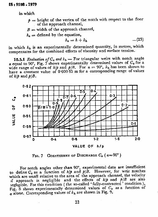
The coefficient of discharge C, has been determined by experiment as a function of three variables ( see Fig. 7 ).
c,- f + , -$ ,a ( > . . . (22)
21
IS : 9108 - 1979
in which
p = height of the vertex of the notch with respect to the floor of the approach channel,
B 3 width of the approach channel,
h e = defined by the equation, h, = h + kh . . . (23)
in which kh is an experimentally determined quantity, in metres, which compensates for the combined effects of viscosity and surface tension.
10.5.1 Evaluation of C, and k,, - For triangular weirs with notch angle a equal to 90”, Fig. 7 shows experimentally determined values of Ce for a wide range of values of h/p and p/B. For a = 90”, kb has been shown to have a constant value of 0.000 85 m for a corresponding range of values of h/F and j/B.
0.62
0.6 1
0.60
095s
0.50
0.57 0 04 04 1.2 1.6 2.0
VALUE OF h/p
Fro. 7 COEFFICIENT OF DISCHARGE C, ( a=90° )
For notch angles other than 90”, experimental data are insufficient to define C, as a function of h/p and P/B. However, for weir notches which are small relative to the area of the approach channel, the velocrty )f approach is negligible and the effects of h/j and p/B are also negligible. For this condition ( the so-called ‘ fully-contracted ’ condition ), Fig. 8 shows experimentally determined values of CB as a function of o alone. Corresponding values of kh are shown in Fig. 9.
22
IS : 9108 - 1979
0.61
0" O-60
::
9 0*58
O-56 0 20 LO 60 80 100 120
VALUE OF NOTCH ANGLE, a (DEGREES)
FIG. 8 COEFFICIENT OF DISCHARGE C’, RELATED TO NOTCH ANGLE 3:
60 80 100
--T-r
120
VALUE OF NOTCH ANGLE, c( ( DEGREES )
FIG. 9 VALUE OF kh RELATED TO NOTCH ANGLE a
23
IS : 9108 - I979
10.5.2 Practical Limitations on a, h/p, P/B, h and # - For reasons related to hazards of measurement-error and lack of experimental data, the Following practical limits are applicable to the use of the Kindsvater-Shen formula:
a) a shall be between 20” and 100”; b) h/p shall be limited to the range shown in Fig. 7 for a - 90”
h/p shall be not greater than O-35 for other values of a; c) P/B shall be limited to the range shown in Fig. 7 for a = 90”
f/B shall be between 010 and l-5 for other values of a; d) h shall be not less than 0.06 m; e) Jo shall be not less than 0.09 m.
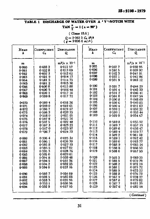
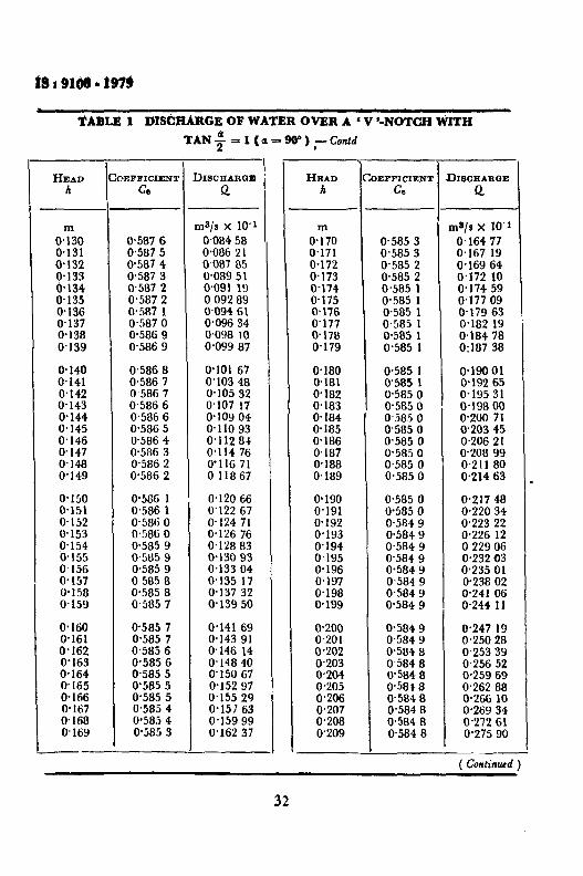
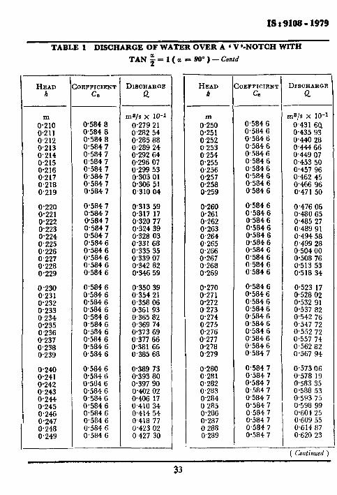
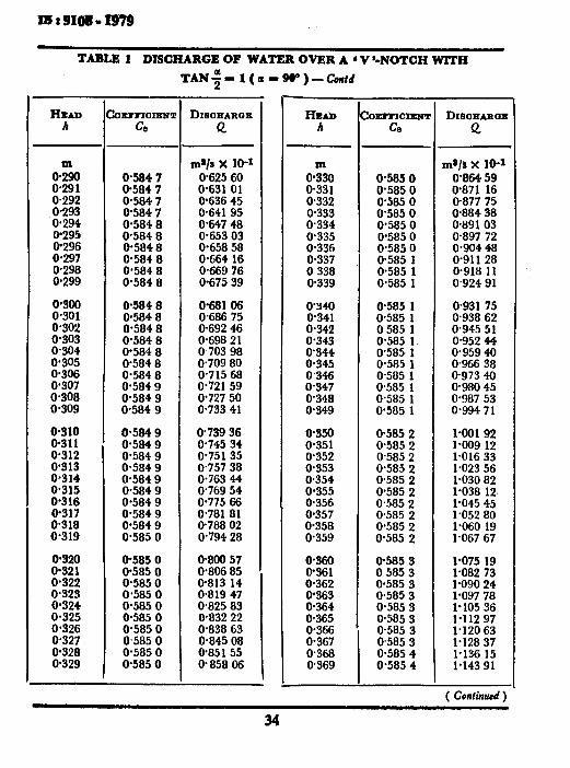
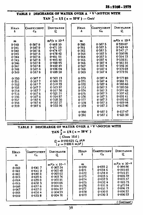
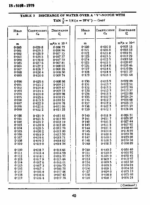
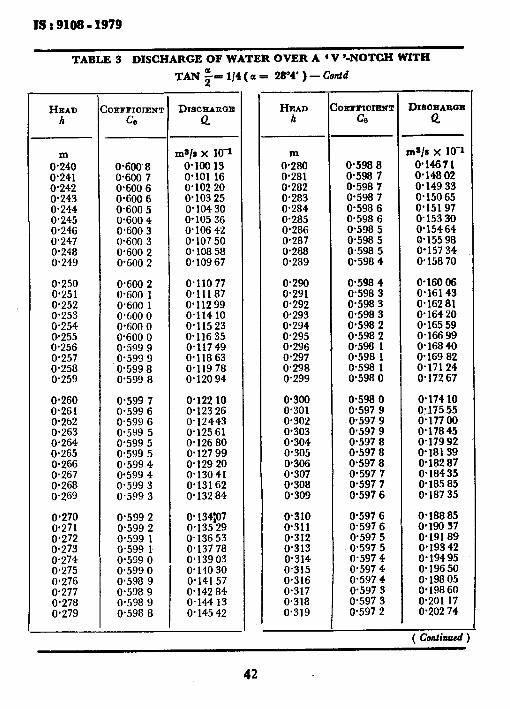
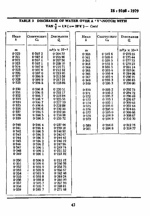
10.6 Formula for Specific Notch Angles ( Fully Contracted Weir ) - BSI* Formula for Three Related Angles - This formula is for notch angles which have a special geometric relationship to each other:
a) tangent a/2 = 1 (a = 90”);
b) tangent a/2 = O-50 ( a = 53”8’ ); and c) tangent a/2 = 0.25 ( a = 28”4’ ),
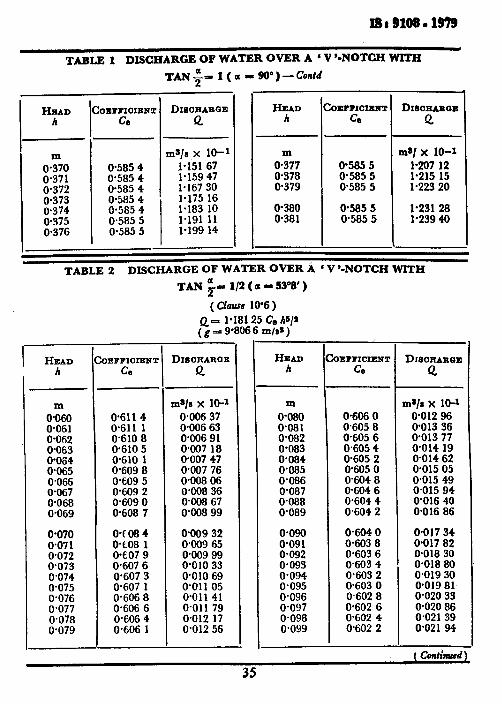
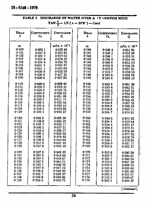
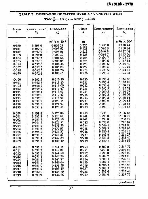
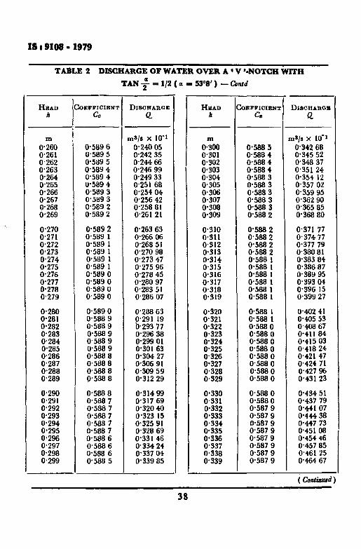
The BSI discharge formula is:
Q = C+tan +-$$I2 . ..(24)
and the experimentally determined values of C and Q for the condition of ‘ full contraction ’ are shown‘in Tables 1, 2 and 3.
Practical limitations applicable to the use of this formula are:
a) h/j shall be not greater than 0’4; b) h/B shall be not greater than 0.2; c) h shall be between 0.05 and 0.38 m; d) p shall be not less than O-45 m; and e) B shall be not less than 1-O m.
10.7 Accuracy of Discharge Coefkients Weirs
- Triangular-Notch - The accuracy of discharge measurements made with a triangular-
notch thin-plate weir depends primarily on the accuracy of the head and notch-angle measurements and on the applicability of the discharge formula and coefficients used. If great care is exercised in meeting the construction, installation, and operational conditions specified in this
*British Standards Institution.
24
IS : 9108 - 1979
standard, uncertainties ( at 95 percent confidence level ) attributable to the coefficients of discharge will be not greater than 1.0 percent. The combination of all uncertainties which contribute significantly to the uncertainty of discharge measurements is trentecl in Il. I~xamples of estimated uncertainties in measured discharge arc given in 12.
11. ACCURACY OF DISCHARGE MEASUREMENTS
11.1 General - The accuracy of a discharge measurement is best express- ed in terms of a statistically determined range of uncertainty. In this instance the measured discharge is the discharge calculated by means of a weir discharge formula, and the uncertainty of the measurement is the range within which the true discharge can be expected to lie 95 percent of the time ( ‘ 95 percent confidence level ’ ).
The uncertainty of a discharge measurement is estimated as the combination of uncertainties in the contributing sources of error. Thus, the relative influence of each contributing source can be assessed to determine whether, with the resources and techniques available, discharges can be measured with suff7cient accuracy for the purpose in hand,
11.2 Sources of Error - The sources of error which contribute to uncertainties in weir discharge measurements can be identified by consi- dering representative discharge filrmulae. For cXarn[Jk, from equations 1 and 21, respectively, simplified discharge formulae are, for rectangular weirs,
Qr = J, [c, LQc IL,“!” ] (25)
and, for triangular weirs
Qt = Jt [ C, ,//s tan: he’/’ 1 . . (26)
in which J is a numerical constant, dependent on the form of the weir but not subject to error. Error in g, the acceleration due to gravity, may be neglected. It follows that the only sources of error which need to be considered are:
a) the discharge coeficient C,;
b) the measured width b or the notch angle a;
c) the measured head h which depends also on the error in the determination oi‘the gauge zero; and
d) the corrective terms k. and Ali dcfinrd in equations 3, 4 and 23.
For those discharge formulae which do not m;~ke use of the cKective- head and width concept, the lib and I;, factors are irrelcvaut, and C,, b, and h, can be replaced by C, b and h.
25
IS t 9108 - 1979
11.3 Uncertainties Due to Different Kinds of Errors - Errors are classified as random or systematic. Random errors are precision or experi- mental errors, which deviate from the mean in accordance with the laws of chance. Systematic errors stem from inaccuracies inherent in the equip- ment and conditions of measurement.
The uncertainty due to random errors can be estimated statistically in terms of the standard deviation. The standard deviation S, of n measurements of a variable y is given by the equation:
r 1 11s
sy = 12 n (g-Y)* 1 1
.a
i=l 1 n-l J
8.227)
in which p is the arithmetic means of the measurements. deviation of the mean is:
The standard
sp= 5 ,.. (28)
If the number of measurements is large enough that their deviations from the mean approach a normal distribution, the uncertainty of the mean is equal to 2Sg for the 95 percent confidence level.
It follows that the range in the value of the measured quantity is equ,@ to J f 2sp. of “uncertainty due
From equations 27 and 28 it is evident that the range to random errors can be reduced by increasing
the-number of measurements.
Because systematic errors are caused by inaccuracies attributable to the equipment and to conditions of measurement, the uncertainty due to systematic errors cannot be reduced by increasing the number of measure- ments. The uncertainty due to systematic errors shall be estimated subjectively on the basis of knowledge of the equipment and techniques involved.
11.4 Errors in Recommended Coefficients -Values of C,, C, kt., and kb used in discharge formulae given in this standard are based on experiments made under different conditions, all believed to satisfy the specifications for standard weir installation and use. The estimated errors in these quantities are based on an assessment of the experiments and a comparison of the results obtained from the recommended formulae. in C,, C, kb and kh are essentially systematic errors.
Thus, the errors
Recommended values of the uncertainty in C, and C to be used under various conditions of measurement are given in 9.8 and 10.7 for
26
1s t 9108 - 1979
.
rectangular and triangular weirs, respectively. In general, the coefficient of discharge is subject to greater uncertainty than other sources of systematic error.
For all applications covered by this standard the uncertainties in kb and kb can be taken to be 0.3 mm. The influence of both factors on the uncertainty in measured discharge is insignificant except at small values of b and A.
11.5 Errors in Quantities Measured by the User - Quantities measured by the user include b, h, and a. Both random and systematic errors occur in this category. Measurements of b and ‘a, for example, involve measurements of fixed dimensions and distances, and errors depend on the equipment and methods used. Consideration of the conditions of measurement enables the user to estimate the uncertainty in these quantities. Measurements of h depends not only on equipment and technique but also on the fluctuation of water level ( for example, in a stilling well or a manometer ). Thus, the -uncertainty in h depends in part on the random uncertainty in the mean of numerous measurements, and it is estimated as the square root of the sum of the squares of the separate uncertainties.
When the uncertainty of a systematic error can be assessed experi- mentally, the value of the uncertainty should be calculated by the method described in 11.3 for random errors. When the uncertainty shall be (stimated from a single measurement subject to systematic error, the u.lcertainty should be calculated as one half the range within which the error is estimated to lie.
11.6 Combination of Uncertainties - In 11.4 and 11.5, systematic and random errors have been distinguished separately. However, because the sign of the systematic errors is not known and because the two types of errors are inextricably linked, they are all treated as random errors when combination of uncertainties is considered.
The following method of calculation should be used to combine the uncertainties which contribute to the overall uncertainty in weir discharge measurements ( at 95 percent confidence level ). For rectangular weirs, from the simplified equations of discharge given in 11.2,
xQr - - ---. --
&,/X2=, + X288 + 1 .52XSB . ..i29)
and, for triangular weirs,
XQt = ---
f&f2C,+ X2 tnn als + 2*52XzhB . . . (30)
in which
x= uncertainty, expressed as a percentage,
27
!S t 9108 - 1939
XQ = uncertainty in the calculated value of the discharge,
xce = uncertainty in the coefficient of discharge,
xb, = uncertainty in the effective width for a rectangular weir,
ckk = uncertainty in the head correction factor, and
2SX - uncertainty in the mean of n readings of the head.
Calculation of the uncertainty in tan a/2 will depend on the method of measurement used. For example, tan a/2 could be determined as the quotient of one-half the top width bt and the vertical height of the notch ht. With associated errors eb,, and eht in the measurement of bt and ht, the uncer- ainty in tan q/2 would be,
Xtana,s = * lOOj/( ;:)2 + (_e)“‘ . ..(33)
For those discharge formulae which do not involve the effective-head and width concepts .!$ and ek6 should be taken to be zero in the preceding equations.
The uncertainty of the discharge measurements is not single valued for a given installation, but will vary with the rate of flow. It is usually desirable, therefore, to consider the uncertainty at several discharges covering the required range of measurement.
28
ISr9199-1979
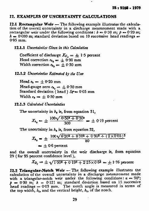
12. EXAMPLES OF UNCERTAINTY CALCULATIONS
12.1 Rectangular Weir - The following example illustrates the calcula- tion of the overall uncertainty in a discharge measurement made with a rectangular weir under the following conditions : b - 0.30 m; fi - 0.20 m; h = 0.080 m; standard deviation based on 10 successive head readings 5 0.05 mm.
12.1.1 Uncertainties Given in this Calculation
Coefficient of discharge Xc, = f 1.5 percent Head correction ekk = f 0.30 mm Width correction d$ = f 0.30 mm
12.X.2 Uncertainties Estimated by the User
Head ej, = f 0.20 mm
Head-gauge zero 9 s f O-30 mm Standard deviation ( head ) Sp 0.05 mm
Width cb = f 050 mm
12.1.3 Calculated Uncertainties
The uncertainty in 6, is, from equation 31,
Xbe - fi load 0.50’ + 0.30s
300 I f 0.19 percent
The uncertainty in h, is, from equation 32,
xh., - rt:
1001/0~202 + 0302 + O-30* + ( 2 x0.05 12 80
re f @6 percent
and the overall uncertainty in the weir discharge is, from equation 29 ( for 95 percent confidence level ),
XQr= =1= 2/w = f 1.76 percent
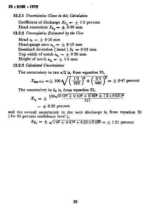
12.2 Triangular-Notch Weir - The following example illustrates the calculation of the overall uncertainty in a discharge measurement made with a triangular-notch weir under the following conditions: a - 90”;
P- 0.30 m; h = @ 12 1 m; standard deviation based on 15 successive head readings = 0.03 mm. The notch angle is measured in terms of the top width, bt, and the vertical height, ht, of the notch.
29
. ._ ‘. --“T---
IS t 9199 - 1979
12.2.1 Uncertainties Gitien in this Calculation
Coefficient of discharge Xc0 = f 1.0 percent Head correction Xk, - f 0.30 mm
12.2.2 Uncertainties Estimated by the User
Head eh = f 0.10 mm Head-gauge zero eh, = f 0.10 mm Standard deviation ( head ) S,- e 0.03 mm Top width of notch dbt = f 0.50 mm Height of notch #At J f 1.0 mm
12.2.3 Calculated Uncertainties
The uncertainty in tan or/2 is, from equation 33,
X tonalr -* lOOZ/(jj$~+($~= &OMpercent
The uncertainty in h, is, from equation 32,
100J0~103 + 0’ 108 + o-30* + ( 2 xom p Xn, = f -
- 121
= rf: 0.28 percent
and the overall uncertainty in the weir discharge is, from equation 30 ( for 95 percent confidence level ),
XQt = f s/ 1*02 + 0.472 + ii.25 x 0.282 = f l-3 1 percent
30
IS 3 9199 - 1979
TABLE 1 DISCHARGE OF WATER OVER A ‘ V ‘-NOTCH WITH