Disclosure to Promote the Right To Information Whereas the Parliament of India has set out to provide a practical regime of right to information for citizens to secure access to information under the control of public authorities, in order to promote transparency and accountability in the working of every public authority, and whereas the attached publication of the Bureau of Indian Standards is of particular interest to the public, particularly disadvantaged communities and those engaged in the pursuit of education and knowledge, the attached public safety standard is made available to promote the timely dissemination of this information in an accurate manner to the public. इंटरनेट मानक “!ान $ एक न’ भारत का +नम-ण” Satyanarayan Gangaram Pitroda “Invent a New India Using Knowledge” “प0रा1 को छोड न’ 5 तरफ” Jawaharlal Nehru “Step Out From the Old to the New” “जान1 का अ+धकार, जी1 का अ+धकार” Mazdoor Kisan Shakti Sangathan “The Right to Information, The Right to Live” “!ान एक ऐसा खजाना > जो कभी च0राया नहB जा सकता ह ै” Bhartṛhari—Nītiśatakam “Knowledge is such a treasure which cannot be stolen” IS 9229 (1979): Inductors for Electromagnetic Interference Suppression [LITD 5: Semiconductor and Other Electronic Components and Devices]
Transcript
Disclosure to Promote the Right To Information
Whereas the Parliament of India has set out to provide a practical regime of right to information for citizens to secure access to information under the control of public authorities, in order to promote transparency and accountability in the working of every public authority, and whereas the attached publication of the Bureau of Indian Standards is of particular interest to the public, particularly disadvantaged communities and those engaged in the pursuit of education and knowledge, the attached public safety standard is made available to promote the timely dissemination of this information in an accurate manner to the public.
इंटरनेट मानक
“!ान $ एक न' भारत का +नम-ण”Satyanarayan Gangaram Pitroda
“Invent a New India Using Knowledge”
“प0रा1 को छोड न' 5 तरफ”Jawaharlal Nehru
“Step Out From the Old to the New”
“जान1 का अ+धकार, जी1 का अ+धकार”Mazdoor Kisan Shakti Sangathan
“The Right to Information, The Right to Live”
“!ान एक ऐसा खजाना > जो कभी च0राया नहB जा सकता है”Bhartṛhari—Nītiśatakam
“Knowledge is such a treasure which cannot be stolen”
“Invent a New India Using Knowledge”
है”ह”ह
IS 9229 (1979): Inductors for Electromagnetic InterferenceSuppression [LITD 5: Semiconductor and Other ElectronicComponents and Devices]
IS : 9229 - 1979
Indian Standard SPECIFICATION FOR
INDUCTORS FOR ELECTROMAGNETIC INTERFERENCE SUPPRESSION
Transformers and Inductors for Electronic Equipment Sectional Committee, LTDC 8
Members SHBI R. P. BAHETI Electronics Corporation of India Ltd, Hyderabad
SHBI B. S. RAO ( Alfemafe ) SRRI J. P. BHABQAVA National Research Development Corporation of
India, New Delhi SHRI M. P. BHATNAUAR ( Alternafe )
SERI G. V. DESAI Electronic Component Industries Association, New Delhi
SHRI M. DAYAL ( Alternate ) DIREOTOR I’ Posts and Telegraph Board, New Delhi SARI B. P. GHOBH National Test House, Calcutta SHRI A. Das GUPTA Philips India Ltd, Bombay
SHRI V. M. BAPAT ( Altsrnatr ) SEBI R. K. JAIN Radio Electronic & Televkion Manufacturers
Association ( RETMA ), Bombay SHRI T. J. DHABHAR ( Alfemate )
KUMARI K. R. JAYA Indian Telephone Industries Ltd, Bangalore SHRI T. G. .VASUDEVAN ( Alternate )
SHRI S. KRISHNAYURTHY Railway Board, New Delhi SHRI JAYARA~AN ( Alternate )
SHRI B. MAJUMDAR The Development Commissioner, Small Scale Industries, New Delhi
SERI S. N~ELAEANTAN Ministry of Drfence ( DGRD ) SIZRI P. K. RAO Ministry of Defence ( DGI )
SHRI S. N, MOHAMMED ( Alternate ) SaRI M. SANKARALINQAM Directorate General of Supplies & Disposala
SHRI D. R. CHANDRAN ( Alternate ) ( DGS&D )
( Continued on page 2 )
@ Copyright 1980 INDIAN STANDARDS INSTITUTION
This publication is protected under the In&n CopVright Act ( XIV of 1957) and reproduction in whole or in part by any means except with written permission of the publisher shall be deemed to be an infringement of copyrlght under the said Act.
IS : 9229 - 1979
( Continued from page 1 )
Members Representing
SHRI P. R. SURYANANDAN Civil Aviation Department, Office of the Director of Civil Aviation, New Delhi
SRRI VISHWANATH ( Altcrnatc ) SHRI P. SURYANARAYAN National Physical Laboratory ( CSIR ), New Delb SHRI R. C. JAJN, Director General, IS1 ( Ex-oficio Member )
Head ( Electronics )
Secretary
SHRI B. K. SHARMA Assistant Dlrector ( Electronics ), ISI
2
IS : 9229 - 1979
Indian Standard SPECIFICATION FOR
INDUCTORS FOR ELECTROMAGNETIC INTERFERENCE SUPPRESSION
0. FOREWORD
0.1 This Indian Standard was adopted by the Indian Standards Institution on 2 July 1979, after the draft finalized by the Transformers and Inductors for Electronic Equipment Sectional Committee had been approved by the Electronics and Telecommunications Division CounciI.
0.2 The object of this standard is to lay down uniform performance requirements and electrical, mechanical and climatic properties of electromagnetic interference suppression inductors, to describe test methods and to give recommendations for classification into categories according to their ability to withstand extremes of temperature, humidity, pressure or mechanical stress.
0.3 The choice of inductor for use either individually or in combination of other components for the purpose of electromagnetic interference supprersion will depend on the type of equipment causing interference. Capacitors and filter units for the purpose of electromagnetic interference suppression are covered by IS : 3723 ( Part I )-197d* and IS : 8880-19787 respectively.
0.4 The limits for electromagnetic interference are covered by IS : 6848-1977x.
0.5 In the preparation of this standard, assistance has been derived from Draft British Standard No. 75/22712 DC ‘Specification for components and filter units for electromagnetic interference ( revision of BS 613 ) ’ issued by the British Standards Institution.
0.6 For the purpose of deciding whether a particular requirement of this standard is complied with, the final value, observed or calculated, expressing the result of a test, shall be rounded off in accordance with IS : 2-1960s. The number of significant places retained in the rounded off value should be the same as that of the specified value in this standard.
*Specification for capacitors for radio interference suppression: Part I General requirements and tests.
tSpccification for filter units for electromagnetic interference suppression. *Specification for limits for electromagnetic interference. §Rules for rounding off numerical values ( rcuiud ).
3
IS : 9229 - 1979
1. SCOPE
1.1 This standard specifies performance requirements and tests for inductors for electromagnetic interference suppression for use in electrical machines, applia.nces and apparatus rated up to 7 kVA, operating from 50 Hz electricity supplies above extra low voltage ( ELV ) and up to and including 240 V single phase or 415 V three-phase. DC rated components are also covered by this standard.
1.2 Suppression components or units for use in motor vehicles are not covered by this standard.
2. TERMINOLOGY
2.0 For the purpose of this standard, the definitions given in IS : 6297 ( Part I )-1971* as well as IS : 8880-1978t shall apply.
3. CLIMATIC CATEGORIES
3.1 Electromagnetic suppression inductors covered by this standard shall belong to one of the following three categories based on their ability to withstand climatic severities:
Climatic Test Severities r---____-h_-____-_-~
Category 1 Category 2 Category 3 C-_-A-_--p
A B
Dry heat -t 125°C +85”C +85”C + 70°C
Cold -55°C -55°C -40°C -10°C
Damp heat ( long term ) 56 days 56 days 21 days 10 days
Rapid change of + 125°C to +85”C to -t85% to Not temperature -55°C -55°C -40°C applicable
*General requirements for transformers and inductors ( power, audio, pulse and switching ) for electric equipment: Part [ General requirements and tests.
tSpecilication for filter units for electromagnetic interference suppression.
4
.
4. QONS’k’RUC%‘XON AND W;ORIGMA#Mi&&’
4.1 Materials - The ind9ctors shall be constructed fiFom. materials free f$qn flaws and other defects. Bg, fpr as, ,pr&cticabJe; ,mtztt+rials &ed for ‘Constrlc+ia~ shall’ be A&e retirdqx?, ndn-<~psplpsjGe’ ahif”?+-cQrro@ve a,nd,shalI not a+cxb moisture.
4.8 BeEminaGona --‘The inductors &all ks previ&d wyit$ swqw, lugs, ‘&@eads or plug in lead type terminations., L
“, NOTE - Lugs, if us’;d, shall hc securad io such a way &bat they do no& r,etatc or
work loose or break away in normal use. 1 ‘, .q i
4.3 Nuts, Screws and Washers - All nuts, scr&s &cl w&%eri, ~htib_&tigSlo& ‘&3hers’ used in the construction of induatons.shali be & standard sizes and threads ( see IS i 4118-1968~ ).
4.4 Finish - All exposed metal parts, such as edges of lmip,atfioqp, brackets and other hardware shall be p_l$~,$~ ,Fainted or otherwIse protested to prevent corrosion. , / 1 \‘I. (. I /
4.5 Workmanship - All parts of the inductors shaEJ be nmnufacttired $.G, o $@roughly workmanlike aanner ,?ga in. ..iacmrdapFe wit+ good engineering practice.
5.1 The following marking information is required for inductors f&r general’ pux$ose Use in‘ filter3 for srippr&sion of electrotiagnetic interference:
4 b)
Type designation and tnanufacturer’s name or trade-mark,
Cl d f
. . Week ( or month ) and year of manufacture ( this may be in code form as in IS : 8186-19X? $,
Inductance and tolerance, and
Rated current.
NOTE - The package shall also be m&ked at least with (p), Cb), (c) and (d) listed above. The inductor shall be &car1 marked with the rated current and as many of the other markings as‘pr%c’tica le.
.i “I.,Iv*i :
5.2 The marking shall be such bs fiat to become illegible &bile in storage and during service through normal ha’ndling.
5,s Any additional marking shall be so appli+ that no confusfofi may arise’.
*IS0 metric screw threads. tMarking codes for values and tolerances of resistors &d capacitors.
5
IS:9229 - 1979
5.4 The inductors may also be marked with the IS1 Certification Mark.
NOW - The use of the IS1 Certification Mark is governed by the provisions of the Indian Standards Institution ( Certification Marks ) Act and the Rules and Regulations made thereunder. The IS1 Mark on products covered by an Indian Standard conveys the assurance that they have been produced to comply with the requirements of that standard under a well-defined system of inspection, testing and quality control which is devised and supervised by IS1 and operated by the producer. IS1 marked products are also continuously checked by ISI for conformity to that standard as a further safeguard. Details of conditions under which a liccnce for the use of the IS1 Certification Mark may be granted to manufacturers or processors, may br obtained from the Indian Standards Institution.
6. DIMENSIONS
6.1 The dimension shall be as specified in the relevant individual specification or by the manufacturer.
7. TESTS
7.1 Classification of Tests
7.1.1 Type Tests
7.1.1.1 Tybe approval procedure - The procedure for type approval shall be in accordance with IS : 2612-1965*.
7.1.1.2 Number of samples - Unless otherwise specified, the number of samples shall be 10 for each current rating/voltage rating and type.
7.1.1.3 Schedule of ppe tests - The inductors shall be subjected to the tests according to Table 1 and in the order as given.
7.1.2 Routirre Tests - The following tests shall be carried out in the order stated:
a) Visual examination ( see 7.4.1 ),
b) Inductance ( see 7.3.1 ),
c) DC resistance ( see 7.3.5 ),
d) Voltage proof ( see 7.3.2 ), and
e) Insulation resistance ( see 7.3.3 ).
7.1.2.1 If during routine tests more than 10 percent of the lot fails, the entire lot may be rejected.
7.1.3 Acceptance Tests - The inductors which have passed the routine tests shall be subjected to these tests. The acceptance tests and the failure criteria shall be as given in Table 2.
*Recommendation for type approval and sampling procedures for electronic components.
IS r9229 - 1979
TABLE 1
GROUP TEST
(1) (2)
0 Visual examination
Inductance
DC resistance
Voltage proof
Insulation resistance
SCHEDULE OF TYPE TESTS
( Clause 7.1.1.3 )
No. OB SAMPLES
(3)
10
CLAUSE REFERENCE
(4)
7.4.1 7.3.1
7.3.5 7.3.2
1 Inductance at maximum rated current
Temperature-rise Robustness of terminations
Soldering ( if applicable_) Rapid change of temperature Vibration Bump Climatic sequence
2 Damp heat ( long term )
3 Endurance
4 Short circuit
7.3.3
-5 7.3.7
7.3.6
7.4.3
7.4.4
7.5.3
7.4.5 7.4.6
7.5.1
7.5.2
7.2 General Conditions for Tests - The general conditions for tests shall be as specified in 6.1 of IS : 6-97 ( Part I )-1971*.
7.3 Electrical Tests
7.3.1 Inductance - The inductance shall be measured at a frequency in the range 50-2000 Hz and shall be within the declared tolerance.
7.3.1.1 As the measured value of the inductance may be function of current, frequency and temperature, these parameters shall be recorded in the test report and shall remain constant throughout the type test.
NOTE 1 - This measurement should be made on a low current ac bridge.
NOTE 2 - In the case where a reference value is required, measurements should be carried out at a frequency of 1 kHz and at a temperature of 25% and extrapolated to zero current.
*Transformers and inductors ( power, audio, pulse, and switching ) for electronic equipment: Part I General requirements and tests.
NOTB - Samples which have been sul&#,d tq:,&stru$ti@ tusks shall not be returned to the lot.
*IS : 25QO ( Part I )-I973 Sampling plans and procedures for inspection by attributes for electronic items. ( Under preparation ).
tD - Destructive, N ;t Non-destructive.
7.3.2 Voltagr Proof - The inductor shall withstand without breakdown the application of an ac test voltage of value as given below:
Maximum Working Voltage Test Voltage
V V
25 and below 50 -
Over 25 to 50 100
Over 50 to 100 300
Over 100 to 175 500
Over 175 to 700’ 230 x Maximum working ., Wo~age
Over 780 and aBdvc ‘l*q’ix ‘Maximum working ’ w&age -I- 1 a00
The test voTtage shall be apphed between winding and the case, if any. In case of single’tiinding inductor and insulated types of i>ductor the voltage is to be applied between a metal foil which is closely wrapped around the component and the winding. The voltage shall be raised at a rate not exceeding 500 V/s alrd shall be maintained at the maximum value for one minute.
8
IS t 9229 - 1979
When this test is carried out as a routine test, the voltage shall be applied for one second only.
7.3.3 Insulation Resistance -This test shall be carried out after the temperature-rise test. Unless otherwise specified, the insulation resistance shall be measured by applying dc test voltages as mentioned below for one minute & 5 seconds between the case and winding, and also between windings, if applicable. The voltage shall not be applied gradually but shall be applied immediately through the internal resistance of the test apparatus. The insulation resistance shall be read after 1 minute & 5 seconds.
Maximum Working Voltage Test Voltage
V V
25 and below 50
Over 25 up to 175 100
Over 175 500
The insulation resistance shall not be less than 1000 MQ.
7.3.4 Short Circuit - A current shall be passed through the inductor for one second which is either 50 times the rated current or that current resulting from the application of the rated voltage to the supply terminals of the inductor with the appliance terminals of the inductor short- circuited, whichever is the less.
7.3.4.1 For P-wire inductors consisting of-two identical coils having a common magnetic core the test shall be carried out as follows:
a) On one coil separately, and
b) On both coils together with the appliance terminals of the inductor shorted together.
7.3.4.2 For S-wire, S-phase inductors consisting of three identical coils having a common magnetic core the test shall be carried out as follows:
a) On one coil separately, and
b) On two coils together with their appliance terminals shorted together.
7.3.4.3 For 4-wire, J-phase inductors consisting of three identical line coils and a neutral coil all having a common magnetic core the test shall be carried out as follows:
a) On one line separately,
b) On the neutral coil separately,
9
IS:9229 - 1979
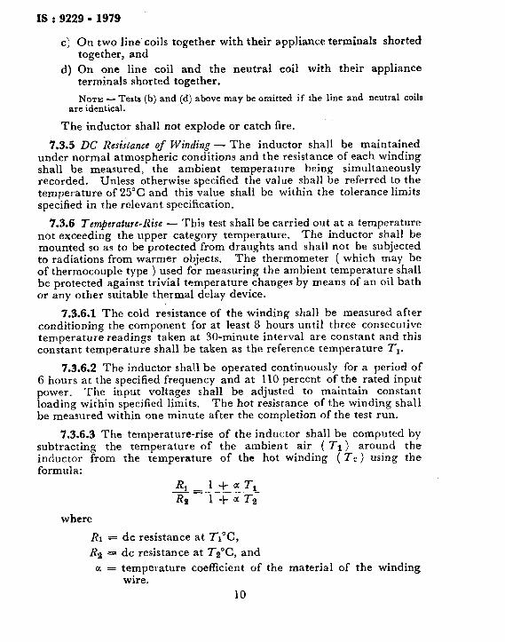
c) On two line coils together with their appliance terminals shorted together, and
d) On one line coil and the neutral coil with their appliance terminals shorted together.
NOTE - Tests (b) and (d) above may be omitted if the line and neutral coils are identical.
The inductor shall not explode or catch fire.
7.3.5 DC Resistance of Winding - The inductor shall be maintained under normal atmospheric conditions and the resistance of each winding shall be measured, the ambient temperature being simultaneously recorded. Unless otherwise specified the value shall be referred to the temperature of 25°C and this value shall be within the tolerance limits specified in the relevant specification.
7.3.6 Temperature-Rise - This test shaII be carried out at a temperature not exceeding the upper category temperature. The inductor shall be mounted so as to be protected from draughts and shall not be subjected to radiations from warmer objects. The thermometer ( which may be of thermocouple type ) used for measuring the ambient temperature shall be protected against trivia1 temperature changes by means of an oil bath or any other suitable thermal delay device.
7.3.6.1 The cold resistance of the winding shall be measured after conditioning the component for at least 8 hours until three consecutive temperature readings taken at 30-minute interval are constant and this constant temperature shall be taken as the reference temperature T,.
7.3.6.2 The inductor shall be operated continuously for a period of 6 hours at the specified frequency and at 110 percent of the rated input power. The input voltages shall be adjusted to maintain constant loading within specified limits. The hot resistance of the winding shall be measured within one minute after the completion of the test run.
7.3.6.3 The temperature-rise of the inductor shall be computed by subtracting the temperature of the ambient air ( 71) around the inductor from the temperature of the hot winding ( T2) using the formula:
*__14aT1 R __- - RB l+aTz
where
RI = dc resistance at Tl’C,
R2 = dc resistance at Tz’C, and
u = temperature coefficient of wire.
10
the material of the winding
IS : 9229 - 1979
The temperature-rise shall not exceed the value stated in the relevant specification.
NOTE - The temperature-rise of any winding or section shall not exceed the value ( X- Y 1, where X is the temperature corresponding to the class of the insulation ( ILC IS : 1271-195G* ) after allowing for hot spot temperature and 2” is the upper category temperature.
7.3.7 Inductance at Maximum Rated Current - The inductance shall be measured at a frequency within the range of 50-2 000 Hz at maximum rated current and shall be within the specified tolerance.
7.3.7.1 As the measured value of the inductance may be a function of current, frequency and temperature, these parameters shall be recorded in the test report and shall remain in the test report and shall remain constant throughout the type test.
NOTE - This measurement should be made at maximum rated current.
7.4 Physical and Mechanical Tests
7.4.1 Visual Examination - The inductor shall be visually examined for compliance with the requirements of marking workmanship and finish.
7.4.2 Dimensions - The dimensions shall be checked for compliance with those specified in the relevant detail specification or by the manufacturer.
7.4.3 Robustness of Terminations - This test shall be carried out in accordance with IS : 9000 ( Part XIX/Set 1 to 5 )-19787.
7.4.3.1 Tensile test - The weight to be applied shall be 2 kg for all types of terminations, except wire terminations. For wire terminations, see Table 3.
7.4.3.2 Bending test - Two consecutive bends shall be applied.
7.4.3.3 Torsion test - Two consecutive rotations shall be applied.
7.4.3.4 Torsion test on screw terminals - For use on nuts or threaded terminations only.
After each of the above tests the inductor shall be visually examined. There shall be no visible damage.
7.4.4 Soldering - The test shall be carried out in accordance with 7.18 of IS : 589-1961$.
*Classification of insulating materials for electrical machinery and apparatus in relation to their thermal stabilitv in service.
tBasic environmental testing procedures for electronic and electrical items: Part XIX Test for robustness of terminations and internal mounting devices.
SBasic climatic and mechanical durability tests for components for electronic and electrical equipment ( rrvisrd ).
11
IS : 9229- 1979
TABLE 3 TENSILE TEST WEIGHT FOR WIRE TERMINATIONS
( Claurc 7.4.3.1 )
CROBS-SECTIONAL AREA CORRESPONDINQ DIAMETER WEIGHT OP THE WIRE OB ROUND WIRE kg
mm= mm
(1) (2) (3)
Up to and including 0.2 Up to and including 0.5 0.5
Exceeding 0.2 and up to and Exceeding 0.5 and up to and 1 including 0.5 including 0’8
Exceeding 0’5 Exceeding 0.8 2
7.4.4.1 The inductance shall be measured as in 7.3.1.
7.4.4.2 Method 2 of the above test shall be applied to wire terminations in the ‘as received’ condition at a point 6.5 mm from the emergence of the wire from the termination. The soldering time shall be 3 s maximum.
7.4.4.3 Terminations other than screw type shall be tested in the ‘as received’ condition using Method 1 of the above test.
7.4.4.4 After the ‘resistance to heat’ test of Method 1 there shall be no visible damage. The inductor shall be allowed to cool to room temperature over a period of 1-2 hours. The inductance shall be measured as in 7.3.1 and shall be within f5 percent of the initial value.
7.4.5 Vibration-The inductance shall be measured as in 7.3.1. The test shall be carried out as in IS : 2106 ( Part XVI )-1971* within the frequrncy iange lo-500 Hz with a severity of 0.75 mm displacement amplitude up to 57.5 Hz, and 98 m/s above that frequency for a duration of six hours by sweeping.
7.4.5.1 After the test, the inductor shall be visually examined and there shall not be any damage or deterioration. The continuity of the winding shall be checked. The inductance shall be measured as in 7.3.1 and shall be within f5 percent ofthe initial value. There shall be no change in insulation resistance when measured at the end of this test.
7.4.6 Bump - The inductance shall be measured as in 7.3.1. Test of Set 2 of IS : 9000 ( Part VII/Set 1 to 5 )-19797 shall be applied with a severity of 390 m/s2 for 4000 bumps of 6 ms duration after which
*kwironmental tests for electronic and electrical equipment: Part XVI Vibration teat.
tRasic environmental testing procedures for electronic and electrical items: Part VII Impact test.
12
IS : 9229 - 1979
the inductor shall be visually examined and there shall be no visible damage. The inductance shall be measured as in 7.3.1 and shall be within 5 percent of the initial value.
7.5 Climatic Tests
7.5.1 Climatic Sequence
7.5.1.1 Dry heat - Test of IS : 9000 ( Part III/Set 1 to 5 )-1977* shall be applied at the upper category temperature.
7.5.1.2 Damp heat ( cyclic ) - Test of IS : 2106 ( Part II )-1962t shall be applied for one cycle. After recovery, the specimen shall be subjected immediately to the cold test.
7.5.1.3 Cold test - Test of IS : 9000 ( Part II/Set 1 to 4 )-1977: shall be applied at the lower category temperature for two hours. The recovery period shall be between four and six hours.
7.5.1.4 Damp heat cyclic ( remaining cycles ) - Test of IS : 2106 ( Part II )-19627 shall be applied.
After completion of these tests, the specimens shall be visually examined. There shall be no visible damage and the marking shall still be legible. The specimens shall satisfy the tests in 7.3.2 and 7.3.3.
The inductance shall be measured as in 7.3.1 and shall be within -f 5 percent of the initial value.
7.5.2 Damp Heat ( SteaG Sfate ) - The inductance shall be measured as in 7.3.1. IS : 9000 ( Part IV )-19795 shall be applied with severity appropriate to the climatic category. There shall be no electrical loading during conditioning of the samples. Standard recovery conditions shall apply but surface moisture may be removed by blotting.
7.5.2.1 After the test the specimens shall be visually examined. There shall be no visible damage and the markings shall still be legible. The inductors shall satisfy the tests in 7.3.2 and 7.3.1. The inductance shall be measured in accordance with 7.3.1 and shall be within f 5 percent of the initial value.
7.5.3 Rapid Change of Temperature - The inductance shall be measured as in 7.3.1. Test shall be carried out as per IS:9000 ( Part XIV )-1978/l.
*Basic environmental testing procedures for electronic and electrical items: Part III Dry heat test.
+Environmental tests for electronic and electrical equipment: Part II Damp heat ( cyclic ) test.
*Basic environmental testing procedures for electronic and electrical items: Part II Cold test.
gBasic environmental testing procedures for electronic and electrical items: Part IV Damp heat ( steady state ).
[IBasic environmrnral testing procedures for electronic and electrical items: Part XIV Change of temperature.
13
IS t 9229 - 1979
7.5.3.1 The duration of exposure shall be 30 min at both high and low temperatures. The recovery time shall be between 1 and 2 h.
7.5.3.2 After the tests, the inductor shall be visually examined. There shall be no visible damage. The inductance shall be measured in accordance with 7.3.1 and shall be within 5 percent of the initial value.
7.5.4 Endurance - The inductor shall be operated at the maximum category temperature for the rated voltage and frequency for 2 000 hours unless otherwise specified in the relevant specification. The loads shall be those for which the inductor is designed. After completion of the specified duration of operation, the inductor shall be exposed to recovery conditions for 24 hours.
7.5.4.1 There shall be no damage so as to impair operations and the markings shall be legible. Voltage proof and insulation tests shall be carried out in accordance with 7.3.2 and 7.3.3. The inductance shall be measured as in 7.3.1 and shall be within f5 percent of the initial value.