ENERGY OPPORTUNITIES TO REDUCE CARBON FOOT PRINT IN IDGH CARBON FERRO CHROME PRODUCTION PROCESS IN A SUB MERGED ARC FURNACE 1 Lalith Samaradivakera, 2 Ganesh Prasad Sahu 1 F AM Tata Steel, e-mail: ls.divakera@tatasteelcom 2 Ferro Alloy Production, Bamnipa4 Tata Stee4 e-mail: [email protected]ABSTRACT High carbon ferrochrome is produced by smelting of chrome ore in a sub merged electrical arc furnace. Chrome ore is reduced to form Fe-Cr thru reduction reaction process using coke . In the reduction reaction a considerable amount of CO-gas is generated. In case of open and semi closed furnace this gas is burnt. In case of closed furnace this gas is sucked out and cleaned by scrubber and can be used as a fuel. It has been observed that the off gas is flared in the atmosphere and thus huge energy goes as waste. There is an opportunity to utilise this CO gas and considerable amount of electrical energy can be saved either by preheating the burden or by utilising this gas to generate electrical energy or both. This paper deals with calculations for the off gas, carbon balancing, and oxygen balancing for one ton of Ferro chrome production and also has attempted to calculate the sensible heat calorific value and its potential to generate power. Ferro Alloys and Mineral division, Tata Steel, India produces high carbon Ferro chrome. It has both open furnace and closed furnace to produce Ferro chrome. The paper is mainly concentrating on its closed type 30 MVA submerged arc furnace at Bamnipal. It has taken initiatives to reduce its carbon foot print. It has been seen that there is a potential to generate around 1. 7 MW power in the current situation, where part of the CO gas is utilised for sintering of pellet and for ladle heating . Further, the sensible heat calculations give clear idea about its potential to generate power. The overall aim of this paper is utilisation of the off gas and sensible heat to help the industry to reduce its carbon foot print and cost. KEYWORDS: Ferro chrome, closed furnace, carbon balancing, oxygen balancing, off gas, calorific values, off gas and sensible heat calculations, flaring, power generation& its utilisation, carbon foot print. INTRODUCTION Tata Steel is a leading manufacturer of High Carbon Ferro Chrome in India. Tata Steel's Ferro Alloys Plants are located in Bamnipal and in Cuttack in India and in Richards Bay in South Africa. The Ferro Alloy Plant at Bamnipal is one of the Units of Ferro Alloys and Minerals Division of TATA STEEL. The Unit was originally set up by MIS ORISSA MINING CORPORATION LTD. (A GOVT. OF ORISSA UNDERTAKING) in 1986, under technical collaboration with Consortium Voist Alpine AG (Linz, Austria) and Outokumpu OY, ESPOO Finland. The plant adopts the OUTOKUMPU process of manufacturing sintered chrome ore pellets in shaft furnace. Sintering in shaft furnace is an old and inefficient technology. Now, sintering is done in steel belt conveyor, which is an efficient and latest technology. As a part of waste gas utilization Tata Steel Bamnipal has replaced the furnace oil which was being used as fuel for sintering furnace by off gas. The furnace here is 30 MVA closed top self baked (Soderberg type) submerged electric arc furnace. It had a production capacity of 50000 MT of charge chrome but due to change in market The thirteenth International Ferroalloys Congress Efficient technologies in ferroalloy industry 925 June 9 - 13, 2013 Almaty, Kazakhstan
Transcript
ENERGY
OPPORTUNITIES TO REDUCE CARBON FOOT PRINT IN IDGH CARBON FERRO CHROME PRODUCTION PROCESS IN A SUB MERGED ARC FURNACE
High carbon ferrochrome is produced by smelting of chrome ore in a sub merged electrical arc furnace. Chrome ore is reduced to form Fe-Cr thru reduction reaction process using coke . In the reduction reaction a considerable amount of CO-gas is generated. In case of open and semi closed furnace this gas is burnt. In case of closed furnace this gas is sucked out and cleaned by scrubber and can be used as a fuel. It has been observed that the off gas is flared in the atmosphere and thus huge energy goes as waste. There is an opportunity to utilise this CO gas and considerable amount of electrical energy can be saved either by preheating the burden or by utilising this gas to generate electrical energy or both. This paper deals with calculations for the off gas, carbon balancing, and oxygen balancing for one ton of Ferro chrome production and also has attempted to calculate the sensible heat calorific value and its potential to generate power.
Ferro Alloys and Mineral division, Tata Steel, India produces high carbon Ferro chrome. It has both open furnace and closed furnace to produce Ferro chrome. The paper is mainly concentrating on its closed type 30 MVA submerged arc furnace at Bamnipal. It has taken initiatives to reduce its carbon foot print. It has been seen that there is a potential to generate around 1. 7 MW power in the current situation, where part of the CO gas is utilised for sintering of pellet and for ladle heating . Further, the sensible heat calculations give clear idea about its potential to generate power. The overall aim of this paper is utilisation of the off gas and sensible heat to help the industry to reduce its carbon foot print and cost.
KEYWORDS: Ferro chrome, closed furnace, carbon balancing, oxygen balancing, off gas, calorific values, off gas and sensible heat calculations, flaring, power generation& its utilisation, carbon foot print.
INTRODUCTION
Tata Steel is a leading manufacturer of High Carbon Ferro Chrome in India. Tata Steel's Ferro Alloys Plants are located in Bamnipal and in Cuttack in India and in Richards Bay in South Africa. The Ferro Alloy Plant at Bamnipal is one of the Units of Ferro Alloys and Minerals Division of TATA STEEL. The Unit was originally set up by MIS ORISSA MINING CORPORATION LTD. (A GOVT. OF ORISSA UNDERTAKING) in 1986, under technical collaboration with Consortium Voist Alpine AG (Linz, Austria) and Outokumpu OY, ESPOO Finland. The plant adopts the OUTOKUMPU process of manufacturing sintered chrome ore pellets in shaft furnace. Sintering in shaft furnace is an old and inefficient technology. Now, sintering is done in steel belt conveyor, which is an efficient and latest technology. As a part of waste gas utilization Tata Steel Bamnipal has replaced the furnace oil which was being used as fuel for sintering furnace by off gas.
The furnace here is 30 MV A closed top self baked (Soderberg type) submerged electric arc furnace. It had a production capacity of 50000 MT of charge chrome but due to change in market
The thirteenth International Ferroalloys Congress Efficient technologies in ferroalloy industry
925
June 9 - 13, 2013 Almaty, Kazakhstan
ENERGY
demand, this plant has switched over to Ferro chrome production from Charge chrome production and the production capacity remained same.
Ferro chrome manufacturing is a power intensive process. It consumes 3400 -3700 Kwh/Mt of Ferro chrome which contributes 30-35 % of total cost. Power is the key for carbon foot print and hence reduction in specific power consumption would greatly help to reduce its carbon foot print and cost of production. Tata Steel in its endeavor to reduce its carbon foot prints has taken various steps. It has mapped its carbon foot print for production of 1 MT of Ferro chrome. Life Cycle Inventory has also been done with the help of ICDA .
In ferrochrome production processes, carbon monoxide is generated by releasing energy when oxygen reacts with carbon during reduction reactions of chromite. This CO gas can be further oxidiz.ed to C02 if mixed with oxygen before leaving the furnace. By this oxidation process, it releases about 3 times the energy released by oxidation of carbon to CO. The potential use of this energy and the corresponding increase in productivity is the economic driving force behind post combustion (PC) technologies.
FERRO CHROME PRODUCTION PROCESS
TATA STEEL FAP, BAMNIPAL
F erro Chrome Production (Agglomeration & S111elting)
-
1. Raw Material Store 9. Furnace Tr;insformer(30MVA) 2. Day bins. 10. Gas C leaning 3. Grinding 11. Slag Granulation 4. Filtering 12. C.lsting 5. Pallet izing 13. Product Handling 6. Sintering 14. J igging 7. Ch;irging 16. Product Stor;ige & Dispatch 8. A rc Furn;ice
Figure 1: Process Flow diagram
The figure I explains the production process flow for Ferro Chrome Production. The chromite ore input is in the form of Friable and Lumpy ore. The friable chrome ore is processed in the GFPS (grinding-3, filtrating-4, palletising-5 & Sintering-6) plant to make pellets. In the GFPS, the chrome ore is ground in the grinding mill after adding water and the slurry is filtered in a drum filter unit then green pellets are formed in the palletising disc, the green pellets are then sintered in the shaft
The thirteenth International Ferroalloys Congress Efficient technologies in ferroalloy industry
926
June 9 - 13, 2013 Almaty, Kazakhstan
ENERGY
furnace. The input to the furnace-8, are pellets, chrome lumps, coke ( reductant) and quartzite (flux).The smelting is done in the submerged arc electrical furnace. The Electrical power to the furnace is fed from 30 MV A furnace transformer - 9. It is a closed type furnace; the photo graph of this furnace is shown in the figure . After smelting, the molten metal and slag are tapped from the furnace. The slug is granulated in the slag granulation pit and the molten metal is casted in the casting bed.
The figure 2 is the simple process flow block diagram is self explanatory to depict the Ferro chrome production process
&mel ttling Reduotion Product
Fines
Figure 2: Production process block diagram
RAW MATERIALS
Different raw materials required for the production of ferrochrome are: c> Friable chrome ore. c> Friable lumpy ore. c> Hard lumpy ore. c> Quartzite. c> Pyroxinite. c> Low ash metallurgical Coke (LAM Coke). c> Coke fines. c> Electrode Paste. c> Bentonite. c> Lime. c> Molasses.
The major raw materials of these are chrome ore and Low ash metallurgical Coke (LAM Coke). Chrome ore is obtained in all the three forms for Tata Steel's own captive mines at Sukinda. LAM coke of very low phosphorous is being procured from China. Electrode paste is being procured from ELKEM. Other raw materials like Quartzite, Lime, Coke dust, Bentonite, Molasses etc are procured from local sources. The specifications of various raw materials are shown below
The thirteenth International Ferroalloys Congress Efficient technologies in ferroalloy industry
927
June 9 - 13, 2013 Almaty, Kazakhstan
ENERGY
Raw Material Specifications
SL . .N"t Material She Chemical Analysis 1 Chrome ore
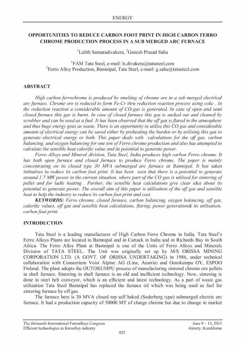
Furnace Details - the details of closed type furnace being used at Tata Steel Bamnipal is shown in figure 3.
RAW MATERIALS
The following are some of the raw materials that are used for producing Ferrochrome, slag and off gas at Tata Steel Bamnipal
1. Sintered pellets 2. Total Hard lumps 3. Total Friable lumps 4. Coke and 5. Quartz
The objective of this document is to describe carbon balance and oxygen balance with fixed composition for ferrochrome alloy and slag.
The thirteenth International Ferroalloys Congress Efficient technologies in ferroalloy industry
928
June 9 - 13, 2013 Almaty, Kazakhstan
•!• Furnace charging system
ENERGY
Closed Top FeCr Furnace Tata Steel, Bamnipal
•!• Furnace shell with tapping syst em
•!• Furnace roof
•:• Gas off-takes and stacks
•!• Electrode columns
•!• High-current supply system
•:• Tapping equipment
•!• Furnace transformer
Ferrochrome calculations for lMT of ferrochrome
Figure 3: The details of closed type furnace
METHODOLOGY AND CALCULATIONS
The methodology in these calculations gives the carbon balance and oxygen balance for the production of ferrochrome from submerged electric arc furnace. Table 1 shows the type of raw materials input needed to produce 1 ton ofFerrochrome.
The typical compositions of all the raw materials are given in the following table 2.
Table 1: Raw materials input into the electric arc furnace for producing 1 ton ofFerrocbrome
Type of raw material Sintered pellet THL TFL Coke Quartz Total
The thirteenth International Ferroalloys Congress Efficient technologies in ferroalloy industry
929
Total. Im 1370
613.22 283.11
523 173.82 2963
June 9 - 13, 2013 Almaty, Kazakhstan
ENERGY
Table 2: Typical composition of different raw materials
Type of raw Values in% material Cr203 Fe Si02 Al203 MgO Cao
The following are some of the reasonable assumptions.
1. Iron present in total hard lumps and total fried lumps is in the form of FeO only. 2. Iron present in the sintered pellets is in the form ofFei03 only. 3. 85% ofCr203 present in the raw materials reacts by direct carbon reduction, 5 % of Cr203
reacts by gaseous reduction with CO gas and the rest remain in the slag. 4. 30% ofFeO present in the raw material reacts by direct carbon reduction, 60 % FeO reacts
by gaseous reduction with CO gas and the rest FeO remains in the slag. 5. Entire F e103 reacts by gaseous reduction with CO gas. 6. Carbon input from coke is 404.42 kg. 7. Moisture present in the total raw material undergoes 100 % conversion by water gas shift
reaction. The following are the reactions that occur in the submerged electric furnace.
Cr6 0 7 + 3C = 2Cr + 3CO (1)
FeO + C = Fe + CO (2)
Si06 + 2C = Si + 2CO (3)
FeO + CO = Fe + C06 (4)
Fe6 0 7 + 3CO = 2Fe + 3C06 (5)
c + co6 -42CO (6)
Cr6 0 7 + 3CO = 2Cr + 3C06 (7)
u6o +co -4ff6 + co6 (8)
The above reactions (1), (2) and (3) are the direct reduction reactions Cr203, FeO and Si02 with carbon in the coke.
Reactions (4), (5) and (7) are the gaseous reduction reactions of FeO, Fe203 and Cr203 with CO gas. Reaction ( 6) is termed as Boudouard reaction. Reaction (8) is termed as water gas shift reaction.
The following table 3 gives the carbon balance over the electric arc furnace.
The thirteenth International Ferroalloys Congress Efficient technologies in ferroalloy industry
930
June 9 - 13, 2013 Almaty, Kazakhstan
ENERGY
Table 3: Carbon balance over electric arc furnace
Consumption Total in ke Carbon goes to Ferrochrome alloy 78 Carbon goes to sludge 5 Carbon requirement for reaction ( 1) 209.18 Carbon requirement for reaction (2) 6.62 Carbon reauirement for reaction (3) 25.71 Carbon for Gasification reaction ( 6) 79.91 Grand Total 404.42
Table 4: Gas balance and analysis
C02as C02 2as Reaction
No Consumption. ke Formation. ke Consumption. ke Fonnation.ke (8) 136.40 214.34 (4) 30.88 48.52 (7) 28.71 45.12 (5) 145.80 229.12 (6) 372.90 292.99 (1) 488.09 (2) 15.44 (3) 60.00 Total 341.79 936.42 292.99 537.10
From the above table 4, following are the conclusions 1. The net CO gas formed and present in the off gas is 936.42-341.79 = 594.63 kg. 2. The net C02 gas formed and present in the off gas is 537.1-292.99 = 244.11 kg. 3. The net H2 that is formed by reaction (8) is 9.74 kg (assuming 100% conversion of H20
present in the burden). Hence the composition of off gas is given in the following table 5 which shows that the major
component of off gas is CO gas followed by C02 and H1.
Table 5: Composition of off gas
Component K2 Kmol % co 594.63 21.24 67.09 C02 244.11 5.55 17.53 H1 9.74 4.87 15.39 Total 848.48 31.65
Heat of reaction for CO+ 1/202 -> C02 281 kJ/mol
Table 6 shows the oxygen balance over the raw material, slag and off gas which are exactly balanced in the total amount. Oxygen in raw material is equal to the oxygen present in the slag+ oxygen present in off gas.
The thirteenth International Ferroalloys Congress Efficient technologies in ferroalloy industry
931
June 9 - 13, 2013 Almaty, Kazakhstan
ENERGY
Table 7 shows the carbon balance over input and output materials to electric arc furnace. The Carbon that enters from coke is equal to summation of carbon present in off gas, ferrochrome alloy and sludge which are exactly balanced.
Table 6: Oxygen balance over raw material, slag and off gas
Raw material K!!: Shu! K!!: Off Gas K!!: Cr203 328.12 Cr203 32.81 co 339.79 FeO and Fei03 112.72 FeO 2.94 C02 177.53 Si02 201.89 Si02 167.61 H20 0 A1203 124.97 A1203 124.97 Mg() 111.62 M!lO 111.62 Cao 8.94 Cao 8.94 H20 77.94 Total 966.21 Total 448.89 Total 517.32
Table 7: Carbon balance over input and output materials to electric arc furnace
Carbon input K!!: Carbon output K!!:
Coke 404.4174 Off gas 321.42 F errocbrome alloy 78
Sludge 5 Total 404.42 Total 404.42
The following table 8 and table 9 give the composition of ferrochrome alloy and slagcomposition respectively. These compositions are fixed up for the calculations needed for off gas compositio~ Carbon balance and oxygen balance.
Table 8: Ferrochrome alloy composition
Metal Cr(85%} Fe Si c Total
Table 9: Slag and its composition
Sbm Cr203 FeO Si02 Ali01 MgO Cao Total
The thirteenth International Ferroalloys Congress Efficient technologies in ferroalloy industry
K!!: 604.29 287.88
30 78
1000.18
932
Ke 155.86 10.29 314.27 265.55 281.15 31.29 1058.41
% 60.42 28.78 3.00 7.80
% 14.73 0.97 29.69 25.09 26.56 2.96
June 9 - 13, 2013 Almaty, Kazakhstan
ENERGY
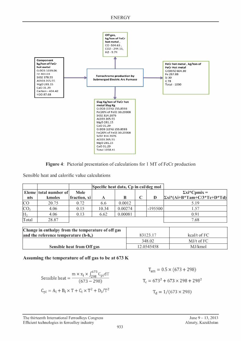
Off g;is, kg/ton of FoCr
hot m et a l , C0-594.63, C02 - 21111.11, H2 - 9.74
Component ·~ kg/ton of FeCr FeCr hot metal , kg/ton of ho t metal Fecr Hot metal Cr203 1039.05 Cr(85%) 604.30 Fe 303.03 Fe 287.88 Si0 2 378.55 ~ Ferrochrome p roduction by
Si 30 - Submerged Electric Arc Furnace -Al203 265.55 C78 MgO 281.15 Tot<il - 1000 Cao 31.29 Carbon - 404.42 H2087.68
' . Slag l<g/ton of FeCr hot I metal Slag l<g Cr203 (15%) 155.8593 Fe(20% or FeO) 10.29308 Si02 314.2676 Al203 265.55
I M gO 281.15 Ca031.29 Cr203 (15%) 155.8593 Fe(20% or FeO) 10.29308 Si02 314.2676 Al203 265.55 Mi;:021H.15 Cao 31.29 To tal 1058.41
Figure 4: Pictorial presentation of calculations for 1 MT of FeCr production
Sensible heat and calorific value calculations
Specific heat data, Cp in cal/de2 mol Eleme total number of Mole
nts km.oles fraction, xi A B co 20.75 0.72 6.6 0.0012 C02 4.06 0.15 10.34 0.00274 H2 4.06 0.13 6.62 0.00081 Total 28.87
Change in enthalpy from the temperature of off gas and the reference temperature (h-hD)
Sensible heat from Off 2as
Assuming the temperature of off gas to be at 673 K
f673
. m x xi x 298
CpidT Sensible heat= (
673 _
298)
- z I z Cpi - Ai + Bi x T + Ci x T + Di T
The thirteenth International Ferroalloys Congress Efficient technologies in ferroalloy industry
933
Exi*Cpmi:x = c D Exi*(Ai+B*Tam+C/3*Tc+D*Td)
5.19 -195500 1.57
0.91 7.68
83123.17 kcaJ/t ofFC 348.02 MJ/t ofFC
12.0545458 MJ/kmol
Tam= 0.5 X (673 + 298)
T, = 6732 + 673 x 298 + 2982
Td = 1/(673 x 298)
June 9 - 13, 2013 Almaty, Kazakhstan
ENERGY
Calculations for Power Generation from OFF GAS
Ke/ton Kmol/ton % Heat released bv reaction. k.J/ton co 594.63 21.24 67.09 =281*21.24*1000=5967579.019 C02 244.11 5.55 17.53 Hi 9.74 4.87 15.39
31.65608 Total e:as How 709.54 Nm3/ton Total gas fiow=total kmol/ton *22.414 Gas utilized for sinterine: 177.38 Nm3/ton All gas for power case Only 7 5% for power case Production rate 6.25 ton/hr Percentae:e of use 0.75 Fraction
Heat How rate to 37297368.87 kJ/hr Heat How rate to 27973026.7 kJ/hr turbine 8908323.51 kcal/hr turbine 6681242.63 kcal/hr Heat rate of kcal/kW turbine 2312 kcal/kWh Heat rate of turbine 2312 h Power capacity 3853.08 kW Power capacity 2889.81 kW
From the above we could see that there is a potential to generate 3.85 MW of power with 100 % gas utilization and 2.89 MW with 75 % gas utilization. However, GE's Genbacher gas engines for power generations are available in multiple of 1. 7 MW and so plant can generate 3 .4 Mw.
CONCLUSION
Ferrochrome production generates large amounts of CO gas ,the composition and volume of which depend on the combination of the raw materials used, feed pre-treatment, furnace type, and operating conditions. These operating conditions include changes in temperature, electrical input, material flow, segregation, and electrode position, as well as the time to tap.
Within open and semi-closed furnace setups the gas generated would be burned off as it leaves the furnace, while a closed furnace setup allows the gas to be extracted by fans, scrubbed, and utilized as fuel. Furthermore, the volume of off-gas generated within a closed furnace setup is much lower than that of any other furnace setup. Off-gas volumes range between 650-850 Nm3/t FeCr, whereas semi-closed and open furnaces generate off-gas volumes of up to 10000-15000 Nm3/t FeCr.
The off-gas as per our typical theoretical calculations shown in this paper consists of 67.09 per cent C0,15.3 per cent H2,17.5 per cent C02. However, it can largely vary depending on the raw material, furnace condition, coke used and its reaction.
Off-gas formed within a closed furnace setup is a source of energy that could be utilized as fuel in a variety of different processes on the plant. It could be utilized for pre-heating or prereduction processes in order to reduce the plant's overall power consumption. The typical off gas volume is calculated and is observed that volume is quite substantial to produce 3.4 MW of power. In the current plant process the part of the off gas is used for sintering and for ladle heating and rest
The thirteenth International Ferroalloys Congress Efficient technologies in ferroalloy industry
934
June 9 - 13, 2013 Almaty, Kazakhstan
ENERGY
is flared. The flared gas can be used either for generating power or for pre heating of the ore. If the installation of pre-heater is feasible, it can reduce the specific power consumption almost by 20% and can enhance the production by more than 10 %. Tata Stee~ Ba.mnipal plant has taken steps to utilize the off gas for power generation and for preheating of the burden to reduce specific consumption.
REFERENCES
[1] Petro Goodies.corn Input gas composition from PVT analysis. [2] Research and Development centre ,Tata Steel's work on carbon and oxygen balancing. [3] Perry's Chemical Engg.Handbook,6th Edition for calculation of sensible heat and calorific
value calculations. [4] Production of Ferro Alloys by M.RISS, Y.KHODOROYSKY, translated from the Russian by
L.V.SAVIN, MIR Publishers Moscow.
The thirteenth International Ferroalloys Congress Efficient technologies in ferroalloy industry
935
June 9 - 13, 2013 Almaty, Kazakhstan
The thirteenth International Ferroalloys Congress Efficient technologies in ferroalloy industry