Disclosure to Promote the Right To Information Whereas the Parliament of India has set out to provide a practical regime of right to information for citizens to secure access to information under the control of public authorities, in order to promote transparency and accountability in the working of every public authority, and whereas the attached publication of the Bureau of Indian Standards is of particular interest to the public, particularly disadvantaged communities and those engaged in the pursuit of education and knowledge, the attached public safety standard is made available to promote the timely dissemination of this information in an accurate manner to the public. इंटरनेट मानक “!ान $ एक न’ भारत का +नम-ण” Satyanarayan Gangaram Pitroda “Invent a New India Using Knowledge” “प0रा1 को छोड न’ 5 तरफ” Jawaharlal Nehru “Step Out From the Old to the New” “जान1 का अ+धकार, जी1 का अ+धकार” Mazdoor Kisan Shakti Sangathan “The Right to Information, The Right to Live” “!ान एक ऐसा खजाना > जो कभी च0राया नहB जा सकता ह ै” Bhartṛhari—Nītiśatakam “Knowledge is such a treasure which cannot be stolen” IS 3156-3 (1992): Voltage transformers, Part 3: Protective voltage transformers [ETD 34: Instrument Transformers]
Transcript
Disclosure to Promote the Right To Information
Whereas the Parliament of India has set out to provide a practical regime of right to information for citizens to secure access to information under the control of public authorities, in order to promote transparency and accountability in the working of every public authority, and whereas the attached publication of the Bureau of Indian Standards is of particular interest to the public, particularly disadvantaged communities and those engaged in the pursuit of education and knowledge, the attached public safety standard is made available to promote the timely dissemination of this information in an accurate manner to the public.
इंटरनेट मानक
“!ान $ एक न' भारत का +नम-ण”Satyanarayan Gangaram Pitroda
“Invent a New India Using Knowledge”
“प0रा1 को छोड न' 5 तरफ”Jawaharlal Nehru
“Step Out From the Old to the New”
“जान1 का अ+धकार, जी1 का अ+धकार”Mazdoor Kisan Shakti Sangathan
“The Right to Information, The Right to Live”
“!ान एक ऐसा खजाना > जो कभी च0राया नहB जा सकता है”Bhartṛhari—Nītiśatakam
“Knowledge is such a treasure which cannot be stolen”
“Invent a New India Using Knowledge”
है”ह”ह
IS 3156-3 (1992): Voltage transformers, Part 3: Protectivevoltage transformers [ETD 34: Instrument Transformers]
IS 3156 ( Part 3 ) : 1992
2ITdhm
VOLTAGE TRANSFORMERS-SPECIFICATION PART 3 PROTECTIVE VOLTAGE TRANSFORMERS
( Second Revision
Second Reprint OCTOBER 1996
UDC 621 314.222.68
)
0 BIS 1992
BUREAU OF INDIAN STANDARDS MANAK BHAVAN, 9 BAHADUR SHAH ZAFAR MARG
This Indian Standard ( Part 3 ) was adopted by the Bureau of Indian Standards, after the draft finalized by the Instrument. Transformers Sectional Committee had been approved by the Electrotechnical Division Council.
This standard was first published in 1966 and was subsequently revised in 1978. Second revision of this standard has been undertaken to bring it in line with the latest developments at international level.
Indian Standards on voltage transformers have been published in four parts :
Part 1 General requirements,
Part 2 Measuring voltage transformers,
Part 3 Protective voltage transformers, and
Part 4 Capacitor voltage transformers.
In the preparation of this standard assistance has been derived from the following:
IEC Pub 186 ( 1987 ) Voltage transformers with Ammendment No. I, December 1988; published by International Electrotechnical Commission.
BS 3941 : 1975. Valtage transformers with latest ammendments, published by British Standards Institution.
For the purpose of deciding whether a particular requirement of this standard is complied with the final value, observed or calcutated, expressing the result of a test or analysis, shall be rounded off in accordance with IS 2 : 1960 ‘Rules for rounding off numerical values ( revised)‘. The number of significant places retained in the rounded off value should be the same as that of the specified value in this standard.
IS 3156 ( Part 3) : 1992
Indian Standafd
VOLTAGE TRANSFORMERS-SPECIFICATI-ON PART 3. PROTECTIVE VOLTAGE TRANSFORMERS
( Second Revision )
1 SCOPE
This standard ( Part 3 ), covers additional require ments for protective voltage transformers.
2 TERMINOLOGY
For the purpose of this standard the detinitions given in -Part 1 of this standard shall apply.
3 GENERAL REQUIREMENTS
The protective voltage transformers shall CornPlY with the requirements of this standard; in addition tb those specified in Part 1 of this standard.
NOTES
1 The requirements of this part apply particularly to transformers which are required to have sufiicient accuracy to operate protective systems at voltages that occur under fault conditions.
2 The requirements of this part &all also apply to protective secondary windings of voltage transformers.
4 ACCURACY REQUIREMENTS
4.1 All voltage transformers intended for protective purposes, shall be assigned one of the accuracy classes specified iri 4.2.
NOTE - Voltage transforms-rs,, intended for pro- tective purposes, with the exception of residual voltage windings, may be assigned a measuring accuracy class in accordance with Part 2 of this standard.
4.1.1 The accuracy class for a protective voltage .transformer is designated by the highest per- missible percentage voltage error prescribed for the accuracy class concerned, from 5% of rated voltage to a voltage corresponding to the rated voltage factor. This expression is followed by the letter “P” for protective voltage transformers and “PR” for 3-phase residual voltage transformers.
4.2 Standard Accuracy Classes
4.2.1 The standard accuracy classes for protective. voltage transformers are “3P” and “6P”.
NOTE - Where transformers are required to have diffcl-cnt error limits at the lower voltayz limit ( 5% rated voltage ) and at the uppsr voltage limit ( the voltage corresponding to rated voltage factor 1.2, 1.5 or I .9 ) spxial agr:ement shall b: made between the manufactul’er and the purchaser.
4.2.2 The standard accuracy classes for 3-phase residual voltage transformers shall be ‘SPR’ and “ 10PR”.
5 LIMITS OF VOLTAGE ERROR AND PHASE DISPLACEMENT FOR PROTECTIVE VOLTAGE TRANSFORMERS
5.1 The,voltage error and phase displacement at rated frequency shall not exceed the values in Table 1 at 5% rated voltage, and at rated voltage multiplied by the rate.d voltage factor ( 1.2, 1.5 or 1.9 ) with burdens of between 25% and 100% of rated burden at a power factor of 0’8 lagging.
5.2 At 2 percent of the rated voltage, the limits of error and phase displacement with burdens of between 25% and l,OO% of rated burden at a power factor of 0’8 lagging shall be twice as high as those given in Table 1.
Table 1 Limits of Voltage Error and Phase Displacement
( Clauses 5.1 and 5.2 )
accuracy Class Percentage Voltage Phase Error Displacement
(1) (2) (3) minutes
3P 1-30 fl20
6P + 6’0 f240 _-
6 DUAL PURPOSE VOLTAGE TRANSFORMER
6.1 Where the transformer has one secondary winding which is intended to served a dual purpose, that is, both for measurement as well as protection, it shall comply with the requirements of both Part 2 and Part 3 of this Standard.
6.2 Where the transformer has two or more separate secondary windings, one for measurement and the others for protection, having the same or different transformation ratios, they shall respectively comply with Part 2 and Part 3 of this Standard.
6.2.1 For Transformers having two or more separate secondary windings ( other than reSidua1 voltage winding ), because of their interdepen- dence, the user should- specify for each winding the simultaneous output ranges -of the other windings at which it must fulfil the requirements of its designated accuracy class. Each winding should fulfil its respective accuracy requirement within its output range whilst at the same time the other winding has an output of any value from zero to 100% of the output range specified for the other winding.
1
IS 3156 ( Part 3 ) : 1992
6.2.2 If the user has not specified as required in 6.2.1 then each winding shall fulfil the require- ments of its designated accuracy class with the other windings (other than residual voltage windings ) simultaneously have any output between 25% and 100% of their, respective rated outputs.
6.2.3 In proving compliance with 6.2.1 or 6.2.2 it shall be sufficient to test at extreme values only.
7 REQUIREMENTS FOR SECONDARY WINDINGS OF SINGLE PHASE VOLTAGE TRANSFORMERS INTENDED TO PRODUCE A RESIDUAL VOLTAGE
7.1 Rated Secondary Voltage
The rated secondary voltage of windings intended to be connected in broken delta with similar windings to produce a residual voltage shall be 110 volts, 1 IO/d7 or 1 IO/3 volts.
NOTE - Where system conditions are such that these values of rated secondary voltages would product a residual voltage that is too low, non preferred higher values may be used but attention is drawn to the need .to take precautions for purposes of safety.
7.2 Output
7.2.1 Rated Output
The rated output of windings, intended to be connected in broken delta with similar windings to product a residual voltage shall be specified in voltamperes. The value of rated output shall be chosen from the values given in 6.4 of Part 1 of this standard; but values of 25, 50 and 100 VA shall be preferred.
NOI‘E -- For a given admittance of rile secondary circuit, the pouer delivered by thi? winding under the conditions snccified in this clause will 1101 rnall~ diUa from the power that it may deliver in the event of a fault when associated with two other similar windings in a three-phase system.
7.2.2 Rated Thermal Limitirg Output
The rated thermal limiting output of a residual voltage winding for a voltage transformer with a voltage factor of 1’9 for 8 hours shall be 15, 25, 75 or 100 VA ( uuderlined values preferred ) or their decimal multiples, related to the rated secondary burden with unity power factor. In respect of such residual voltage windings, the definition in 3.23 of Part 1 shall be modified to limit the rated thermal limiting output for a duration of only 8 hours.
NOTE - Since the residual voltage windiilgs al-e connected in broken delta, these windings are only loaded under fault conditions.
7.3 Accuracy Class
The accuracy class for a residual voltage winding shall be 6P as defined in 4.1.2, 4.2.1 and 5.
NOTES
1 If a residual voltage winding is used for special purposes, other standard accuracy class in accordance with 4.2.1 can be agreed between manufacturer and purchaser. 2 If th: residual voltage winding is used only for damping purposes, an accuracy class designation is not necessary.
8 REQUIREMENTS FOR RESIqUAL VOLTAGE THREE PHASE TRANSFORMERS
8.1 Rated Residual Voltage
The rated residual voltage of a 3 phase residual voltage transformer shall be as follows:
a) .For effectively earthed 1 x rated residual neutral-transformers voltage as defined
at 7.1
b) For isolated neutral 3 x rated residual voltage-transformers voltage as defined
at 7.1
8.2 Limits of Voltage Error and Phase Displacement
The voltage error and phase displacement, deter- mined at the terminals of the transformers (including the effect of such fuses or resistors supplied as and integral part of a 3-phase residual voltage transformer) at rated frequency when tested in accordance with 10.2.1.1 shall not exceed the values given in Table 2 with burdens of any value between 25% and 100% of the rated burden of the residual voltage winding and at a power factor of 0’8 lagging.
Table 2 Limits of Volta& Error and Phase Displacement for Residual Voltage
Transformers
( Clurlsrs 8.2 nrln 10.2.1.1 )
hXWXC~ ChSS Voltage Error Phase Disp!acement
(1) (2) (3) Percent minutes
5 I’R _t 5‘0 +200
10 PII fl0‘0 zk600
8.3 Limit of Error in Residual Voltage
The voltage at the terminals of the residual voltage winding shall not exceed 3 percent of the rated residual voltage under conditions given in 10.2.1.2.
9 MARKING
9.1 All the relevant particulars shall be marked in accordance with 8 of Part 1 of this Standard. In case of Voltage Transformers required to meet combination of output and accuracy classes, the necessary information should also be provided.
10 TESTS
10.0 The following tests shall be carried out in addition to the tests given in Part 1 of this Standard.
2
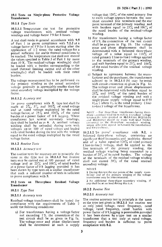
10.1 Tests on Single-phase Protective Voltage Transformers
10.1.1 T~,pe Tests
10.1.1.1 Temperature rise test for protective voltage transformers with residual voltage windings and voltage factor 1’9 for 8 hours.
A test shall made in general accordance with 9.5 of Part 1 to prove compliance wit!1 7.2.2 at a voltage factor of 1’9 for 8 hours starting after the application of 1’2 times the rated voltage for a period sufficient for stable thermal conditions to be reached. The temperature rise shall not exceed the values specified in Table 3 of Part 1 by more than IO K. The residual voltage winding(s) shall be loaded with a burden corresponding to the rated thermal limiting output and all rhe other winding(s) shall be loaded with their rated burden.
The voltage mcasurcment has to be performed 011 the primary winding as the actual secondary volt:tge generally is appreciably smaller than the rated secondary voltage multiplied by the voltage factor.
10.1.1.2 Acctuhcy test
To prove compliance with 5, type test shall be made at 2%, 576. and 100% of rated voltage and at rated voltage multiplied by the rated voltage factor, at 25;/, and 100% of the rated burden at a power factor of 0 8 lagging. \!‘here transformer has several secondary windings, they shall be loaded as in 6. A residual \oltagc winding shall be unloaded during teqts with voltages up to 100 of rated ~oltagc and loaded with rated burden during the test with the voltage equal to the rated voltage multiplied by the rated voltage factor.
10.1.2 Rozrtirle 7ksts
10.1.2.1 Accmcy icst
The routine tests for accuracy are in pl-inciple the same 3s the type test in 10.1.1.2 but routine tests may be carried out at 100 percent of rated voltage and at 25% and 100% of rated burden at a power factor of 0’8 lagging provided it has been shown by type tests on a similar transformer that such a redL!ced number of tests is sufiicient to prove compliance with 5.
10.2 Tests on Three-phase Residual Voltage Transformer
103.1 Type Test
10.2.1.1 Accuracy tesfs
Residual voltage transformers shall be tested for compliance with the requirements of Table 2 under the following conditions:
a) For transformers having a voltage factor not exceeding 1’5, the connection of the test circuit shall be as given in Fig. la. The voltage error and phase displacement shall be determined at such a supply
b)
cl
IS 3156 ( Part 3 ) : 1992
voltage that 1507: of the rated primary line to earth voltage appears between the non- short circuited line terminals and the star point terminal of the primary winding and wifh burdens equal to 25% and IOOO’, of the rated burden of the residual voltage winding.
For transformers having a voltage factor of 1’9, the connections of Lhe test circuit shall be as given in, Fig. 1 b. The voltage error and phase displacement shall be determinated with a balanced three-phase voltage of a value equal to 110% of rated primary ( line-to-line ) voltage applied to the terminals of the primary winding, and with burdens equal to 25% and 100% of the rated burden of the residual voltage winding.
Subject to agreement between the manu- facturer and the purchaser, the transformers referred to in 10.2.1.1 (b) may he tested with circuit connection as gibon in Fig. lc. The voltage error and phase displacement shall be determined with burdens equal to 25% and 100% of the rated burden of the residual voltage winding and with a single-phase supply voltage equal to 0’55 r/,,\/:( where ii,, is the rated primary ( line- to-line ) voltage of the transformer.
10.2.1.2 1-o prove compliance with 8.2, a ba!nnced three-phase voliage, containing 110 signific,tnt third harmonics and multiples thereof and of a value equal 10 120% of rated primary ( line-to-line) voltage, shall be applied to the line terminals of the prilnary winding, the residual voltage winding being connected to a burden of 25’); of its rated burden. The voltage at the terminals or the residual voltage winding shall not exceed 30”/, of the rated residual secondary voltage.
NO:‘I- S
1 Ijuring this test the star points of the supply trans- forlner and of thz primary winding of the voltage transfol-mcr may be interconnected.
2 An additional three-phase secondary winding, if any shail be at 110 load during this test.
10.2.2 Rorrtilrc Tesr
10.2.2.1 Accurncy lest
The routine accuracy test in principle is the same as the type test given in 10.2.1.1 but routine test at only rated voltage, rated frequency, rated voltage,. rated frequency, rated burden with power factor of 0’8.lagging is permissible provided it has been shown by a type test on a similar transformer that a test only at rated voltage, frequency and burden is sufficient to prove compliance with 8.2.
3
IS 3156 ( Part 3 ) : 1992
3-PHASE SUPPLY TRANSFORMER
TRANSFORMER UwER TEST
PRIMARY WINDING
RESI~JA~GVOLTAGE
1A Circuit for Accuracy Test on the Residual Voltage Winding of a Transformer having a Rated Voltage Factor not Exceeding 1.5 [ see 10.2.1.1 (a) ]
TRANSFORMER UNDER
J-PHASE SUPPLY TRANSFORMER
TEST PRIMARY RESIDUAL VOLTAGE WINDING WINDING
L I
OURDEN
STANDARD VOLTAGE TRANSFOR-
:=3 MER
MEASURING
I I - APPARATUS
1B Circuit for Accuracy Test on the Residual Winding of a Transformer having a Rated Voltage Factor of 19 [ see 10.2.1.1 (b) ]
SINGLE-PHASE SUPPLY TRANSFORMER _
TRANSFORMER UNDER TEST
PRIMARY WINDING
RESWlfIIL$AlsGVOLTAGE
1C Alternative Circuit for Accuracy Test on the Residual Voltage Winding of a Transformer having a Rated Voltage Factor of 1.9 [ see 10.2.1.1 (c) ]
FIG. 1 CIRCUIT FOK ACCURACY TEST
4
Bureau of Indian Standards
BIS is a statutory institution established under the Bureau ofIndian Standards Act, 1986 to promote harmonious development of the activities of standardization, marking and quality certification of goods and attending to connected matters in the country.
Copyright
BIS has the copyright of all its publications. No part of these publications may be reproduced in any form without the prior permission in writing of BIS. This does not preclude the free use, in the course of implementing the standard, of necessary details, such as symbols and sizes, type or grade designations. Enquiries relating to copyright be addressed to the Director (Publications), BIS.
Review of Indian Standards
Amendments are issued to standards as the need arises on the basis of comments. Standards are also reviewed periodically; a standard along with amendments is reaffirmed when such review indicates that no changes are needed; if the review indicates that changes are needed, it is taken up for revision. Users of Indian Standards should ascertain that they are in possession of the latest amendments or edition by referring to the latest issue of ‘BIS Handbook’ and ‘Standards: Monthly Additions’.
This Indian Standard has been developed from Dot : No. ETD 34 (29 18)
Amendments Issued Since Publication
Amend No. Date of Issue Text Affected
BUREAU OF INDIAN STANDARDS
Headquarters:
Manak Bhavan, 9 Bahadur Shah Zafar Marg, New Delhi 110002 Telephones : 323 0131,323 83 75,323 94 02
Regional Offices :
Telegrams : Manaksanstha (Common to all offices)
T&phone
Central : Manak Bhavan, 9 Bahadur Shah Zafar Marg 323 76 17 NEW DELHI 110002 3233811
Eastern : l/14 C. I.T. Scheme VII M, V. I. P. Road, Maniktola 337 x4 99,337 85 61 CALCUTTA 700054 337 86 36, .<3? 9 1 30