CES TRANSACTIONS ON ELECTRICAL MACHINES AND SYSTEMS, VOL. 3, NO. 2, JUNE 2019 117 1 Abstract — Through its new technology the ISCAD system provides up to 300 kW with a safe-to-touch 48 Volt battery. This results in a high-performance drive that is intrinsically electrically safe. The novel machine design requires new concepts for power electronics, control systems, and integration strategies. Further degrees of freedom yield to challenges and even more important to possibilities for all kinds of applications. The innovation of the design will be explained and adjustments for power electronics and control will be worked out. The focus of this paper is the 3 rd generation of Intelligent Stator Cage Drive (ISCAD) prototypes. This first integrated and compact prototype has been used to re-equip a Geely Emgrand EV. The entire system and the mentioned process are described in detail. In addition, the in-house designed 48 V battery is highlighted. Simulations and measurements give an overall demonstration of the potential and the current status of the drive. Index Terms — 48 Volt, BEV, car Integration, electromobility, ISCAD, traction drive. I. ELECTROMOBILITY HE electromobility is one of the great innovations of the current time. Car manufacturers from all over the world announce new strategies to ban combustion engines and push electromobility. Nowadays the two biggest markets for passenger car production and sales are China and the EU. In order to bring on “new energy” vehicles, a comprehensive charging infrastructure and automated driving, both regions just published a cooperation. Therefore, the European Automobile Manufacturers’ Association (ACEA) and the Chinese Association of Automobile Manufacturers (CAAM) signed a cooperation agreement in the beginning of 2019 [1]. Manuscript was submitted for review on 26, April, 2019. The authors would like to thank Chaowei Power Co., Ltd for supporting the work presented in this publication S. Runde is with the volabo GmbH, working as an embedded system engineer(e-mail: [email protected]) A. Baumgardt works as head of drive control in the volabo GmbH in the field of low voltage high power traction.(e-mail: [email protected]) O. Moros has been motor developer with volabo GmbH.(e-mail: [email protected]) B. Rubey works as a developer of power electronics in respect to packaging, safety, cooling and system integration at volabo GmbH.(e-mail: [email protected]) D. Gerling has been Full Professor and Head of the Institute of Electrical Drives, Universitaet der Bundeswehr Muenchen.(e-mail: [email protected]) Digital Object Identifier 10.30941/CESTEMS.2019.00017 This is only one example for the progress in electromobility. New players are entering the market and present new technical concepts. Within the progress, Battery Electric Vehicles (BEV) become more affordable. Simultaneously, the acceptance of electric drives and the environmental awareness rises. Especially within the biggest market - China - this results in exploding sales. Comparing the electric vehicle sales in China in the 1 st quarter to the 4 th quarter of 2017, the number of sales more than quadrupled [2]. The most expensive part in BEVs is still the battery pack. Through new global players and oversupply the prices are constantly decreasing [3]. This leads to even more affordable and also competitive passenger EVs in comparison to cars with a combustion engine. These changes indicate that the breakthrough for electric drives is already there. II. STATE OF THE ART Current EVs use conventional electric motors with copper windings in the stator. Despite the different coil winding technologies, the slot filling factor of electric machines is only around 50 % and additional losses occur due to the stator end winding. Moreover, these wound machines have a fixed number of magnetic poles. Consequently, they have only one maximum efficiency operation point. Thereupon the efficiency decreases especially in partial load. In addition, these machines are expensive in production due to the high degree of manual work and complex automation. Current investigations regarding the hair-pin winding show that material usage and costs were hardly improved by this winding method. The recognition that the currently used technology with distributed and concentrated windings has been known for decades [4] and has only made little progress in terms of material use and production costs, is sobering. Especially when it is considered that the stator windings cost up to 40 % of the whole machine (example: 120 kW induction machine in 60s manufacturing cycle) [5]. Most of the Original Equipment Manufacturers (OEMs) set up an individual voltage level in their EVs. These voltage levels reach from 300 to 800 Volt. Since they are above the protection limit of 60 Volt, they are called High Voltage (HV) Vehicles. Because of possible danger from electrocution, HV-Systems have special safety requirements. Even in production, maintenance, and recycling all workers need to have HV-instructions. This raises the costs for costumers from purchase to disposal of the EV. Furthermore, the possible danger from electrocution particularly in case of emergency ISCAD - Design, Control and Car Integration of a 48 Volt High Performance Drive S. Runde, A. Baumgardt, O. Moros, B. Rubey, and D. Gerling (Invited) T
Transcript
CES TRANSACTIONS ON ELECTRICAL MACHINES AND SYSTEMS, VOL. 3, NO. 2, JUNE 2019 117
1Abstract — Through its new technology the ISCAD system provides up to 300 kW with a safe-to-touch 48 Volt battery. This results in a high-performance drive that is intrinsically electrically safe. The novel machine design requires new concepts for power electronics, control systems, and integration strategies. Further degrees of freedom yield to challenges and even more important to possibilities for all kinds of applications. The innovation of the design will be explained and adjustments for power electronics and control will be worked out. The focus of this paper is the 3rd generation of Intelligent Stator Cage Drive (ISCAD) prototypes. This first integrated and compact prototype has been used to re-equip a Geely Emgrand EV. The entire system and the mentioned process are described in detail. In addition, the in-house designed 48 V battery is highlighted. Simulations and measurements give an overall demonstration of the potential and the current status of the drive.
Index Terms — 48 Volt, BEV, car Integration, electromobility,
ISCAD, traction drive.
I. ELECTROMOBILITY HE electromobility is one of the great innovations of the current time. Car manufacturers from all over the world
announce new strategies to ban combustion engines and push electromobility. Nowadays the two biggest markets for passenger car production and sales are China and the EU. In order to bring on “new energy” vehicles, a comprehensive charging infrastructure and automated driving, both regions just published a cooperation. Therefore, the European Automobile Manufacturers’ Association (ACEA) and the Chinese Association of Automobile Manufacturers (CAAM) signed a cooperation agreement in the beginning of 2019 [1].
Manuscript was submitted for review on 26, April, 2019. The authors would like to thank Chaowei Power Co., Ltd for supporting the
work presented in this publication S. Runde is with the volabo GmbH, working as an embedded system
engineer(e-mail: [email protected]) A. Baumgardt works as head of drive control in the volabo GmbH in the
field of low voltage high power traction.(e-mail: [email protected])
O. Moros has been motor developer with volabo GmbH.(e-mail: [email protected])
B. Rubey works as a developer of power electronics in respect to packaging, safety, cooling and system integration at volabo GmbH.(e-mail: [email protected])
D. Gerling has been Full Professor and Head of the Institute of Electrical Drives, Universitaet der Bundeswehr Muenchen.(e-mail: [email protected])
Digital Object Identifier 10.30941/CESTEMS.2019.00017
This is only one example for the progress in electromobility. New players are entering the market and present new technical concepts. Within the progress, Battery Electric Vehicles (BEV) become more affordable. Simultaneously, the acceptance of electric drives and the environmental awareness rises. Especially within the biggest market - China - this results in exploding sales. Comparing the electric vehicle sales in China in the 1st quarter to the 4th quarter of 2017, the number of sales more than quadrupled [2].
The most expensive part in BEVs is still the battery pack. Through new global players and oversupply the prices are constantly decreasing [3]. This leads to even more affordable and also competitive passenger EVs in comparison to cars with a combustion engine. These changes indicate that the breakthrough for electric drives is already there.
II. STATE OF THE ART Current EVs use conventional electric motors with copper
windings in the stator. Despite the different coil winding technologies, the slot filling factor of electric machines is only around 50 % and additional losses occur due to the stator end winding. Moreover, these wound machines have a fixed number of magnetic poles. Consequently, they have only one maximum efficiency operation point. Thereupon the efficiency decreases especially in partial load. In addition, these machines are expensive in production due to the high degree of manual work and complex automation. Current investigations regarding the hair-pin winding show that material usage and costs were hardly improved by this winding method. The recognition that the currently used technology with distributed and concentrated windings has been known for decades [4] and has only made little progress in terms of material use and production costs, is sobering. Especially when it is considered that the stator windings cost up to 40 % of the whole machine (example: 120 kW induction machine in 60s manufacturing cycle) [5].
Most of the Original Equipment Manufacturers (OEMs) set up an individual voltage level in their EVs. These voltage levels reach from 300 to 800 Volt. Since they are above the protection limit of 60 Volt, they are called High Voltage (HV) Vehicles. Because of possible danger from electrocution, HV-Systems have special safety requirements. Even in production, maintenance, and recycling all workers need to have HV-instructions. This raises the costs for costumers from purchase to disposal of the EV. Furthermore, the possible danger from electrocution particularly in case of emergency
ISCAD - Design, Control and Car Integration of a 48 Volt High Performance Drive
S. Runde, A. Baumgardt, O. Moros, B. Rubey, and D. Gerling (Invited)
T
118 CES TRANSACTIONS ON ELECTRICAL MACHINES AND SYSTEMS, VOL. 3, NO. 2, JUNE 2019
remains. The complexity, high costs and especially the safety
concerns pose challenges to mass-production of these State-of-the-Art drives. Electric machines have even more potential than the old concepts promise. The Intelligent Stator Cage Drive (ISCAD) is a novel high-performance traction drive developed on the basis of these old concepts but sets innovation beyond. It mainly addresses the issues mentioned before and sets a new standard for mass production traction drives. With the new system, complexity is taken from the hardware to the software and costs over the whole live-cycle can be easily saved. In addition to that the ISCAD is intrinsically electrically safe due to the low voltage level of 48 V [6].
III. THE INTELLIGENT STATOR CAGE DRIVE
A. Introduction Contrary to the standard concepts for machines with copper
coils the ISCAD uses massive aluminum bars in the stator. As shown in Fig. 1 those stator bars are connected at one axial end as a neutral point [7]. The aluminum bars are displayed in dark grey, the isolation in light grey.
Fig. 1. ISCAD Stator Cage with massive aluminum bars instead of copper coils that are connected at one axial end. The aluminum bars a colored in dark grey, the isolation in light grey.
With this technology, slot filling factors of almost 100 % can be achieved. This allows to replace the copper by lighter and less expensive conductor material such as aluminum. In addition, the simplified structure of the stator winding significantly reduces the manufacturing costs, while at the same time reducing material costs.
Every aluminum bar is fed by a dedicated power electronics unit. These consist of simple half-bride modules. This results in a multiphase and multipole machine and enables various possibilities in control and thus in applications. The special design combines advantages of distributed and concentrated windings. For example, the air gap field has an exceptionally high quality and the “end winding”, formed by a flat aluminum ring, is extremely compact.
B. Multi-Phase Design Advantages In general, the ISCAD-Stator is possibly combined with any
kind of rotor. However, an asynchronous design with a squirrel
cage rotor is used in the 3rd Generation of ISCAD-prototypes. Because of the asynchronous design, there is no need of rare-earth materials in the whole drive. Only iron and aluminum are used both in the rotor and in the stator. The individual control of every phase allows to set any desired number of pole pairs and adapt to the current load in order to optimize efficiency in every operation point. A multipole operation also allows a soft cross-fading of the pole numbers. Thereby it is possible to adjust the number of poles during operation. Another very positive effect of the pole switching is the possibility of reducing rotor losses and thermal relief of the rotor by a smaller slip at a higher number of poles. A high-pole operation with high torque requirements relieves the short-circuiting ring, since its current is inversely proportional to the number of pole pairs. This allows a more compact design and at the same time a cooler operation. Fig. 2 shows this principle of the load-dependent pole number. In addition, it displays an overload area. This area is not anymore defined by a voltage limit, but thermally. That means that the overload range is electrically accessible and only thermally limited. It enables short periods of operation in the overload area if required and thermally possible.
Fig. 2. Principle of the load-dependent pole number setting and overload capability with the stator cage drive. p1 equals a pole number of two, p4 equals a pole number of eight.
C. Safety Concerns A small induced voltage results due to the low number of
turns. Therefore, the System voltage is around 48 V. This means that the whole system is electrically safe to touch. The contact protection limit is at 60 V DC. The 48 V voltage level is set for a simple reason. Even when the drive is used as a generator, while recuperation, the voltage stays below the protection limit.
D. Overall Design The combination of a high number of phases and a low
operation voltage enables the implementation of high-power applications in the range of 30 to 300 kW, where the phase currents are limited to a few hundred amperes. These conditions do not require any special power electronic components. The conventional MOSFET technology serves all requirements. A simplified CAD model of the Intelligent Stator Cage Drive is shown in Fig. 3. The stator package and the stack are pictured transparent to display the stator cage, which is colored in red. The squirrel cage rotor is located right in the middle of the stator cage and displayed in light blue. The
RUNDE et al.: ISCAD – DESIGN, CONTROL AND CAR INTEGRATION OF A 48 VOLT HIGH PERFORMANCE DRIVE 119
power electronics and control package is illustrated in blue. The compact design allows a simple cooling strategy with only one water cooling circuit for machine, power electronics and control package.
Fig. 3. Simplified CAD Model of the ISCAD System including stator cage in red, the squirrel cage rotor in light blue and the Control Unit within the power electronics in blue.
IV. POWER ELECTRONICS
A. Innovations in the Inverter ISCAD provides an electrically safe unit with high
redundancy due to its high number of phases. Since the inverter consists of dedicated half-bridges it is easy to modify the overall number of phases for different power classifications [8]. By feeding each bar with one half-bridge, the current can be controlled individually to provide a high quality MMF. Although the number of phases and consequently the number of semiconductors, drives and measurement circuits of the promoted system are higher compared to high-voltage drivetrains, the overall costs are reduced significantly. Mainly, low-voltage applicable MOSFETs are cheaper than their high-voltage IGBT counterparts. Additionally, high-voltage safety measures such as galvanic isolation, battery disconnector or interlock monitoring are negligible. Design rules such as clearance and creepage distances for high-voltage systems do not need to be complied with, thus reducing the required volume.
A further advantage of MOSFET-based inverters is the higher efficiency compared to IGBT-based inverters, especially in partial load, due to their linear behavior between current and forward voltage [9],[10]. Fig. 4 shows a normalized comparison between an ISCAD and a Tesla Model S inverter dependent on the electrical output power. The parameters used for this loss calculation are disclosed in Table I. The illustrated efficiency comparison between MOSFET and IGBT-based inverters verifies the improvements in partial load, where the MOSFET-based efficiency rises up near to 1, whereas the highest efficiency of IGBT-based inverter is only reachable at maximum output power.
B. Construction / Design As already mentioned, the inverter consists of individual
half-bridges. A high current PCB (printed circuit board) with solid copper bars ensures low ohmic resistances and reduces the
Fig. 4. Efficiency comparison between ISCAD and Tesla Model S inverter dependent on the electrical output power; blue: MOSFET-based (ISCAD); red: IGBT-based (Tesla Model S inverter) [10].
TABLE I PARAMETERS OF THE ISCAD INVERTER FOR POWER LOSS CALCULATION
Symbol Quantity Value
Uac,rms Output phase voltage rms value 14,0 V Qrr Reverse recovery charge 318 nC UDD Driver output voltage 15 V tri Current rising time 80 ns tru Voltage rising time 31,6 ns tfi Current falling time 80 ns tfu Voltage falling time 24,8 ns RAC, Cabling AC cabling 20 µΩ RDC, Cabling DC cabling 38,8 µΩ RESRn Resistance of snubber capacitor bank 180 µΩ RESR, e-cap Resistance of DC-Link capacitor bank 140 µΩ
RHCONn/RLCONn DC contact resistances of half-bridges 100 µΩ ± 0,15 µΩ
RDC-, RDC+ DC contact resistance of DC board 5,3 µΩ ± 0,25 µΩ
current density to an appropriate value [10]. The top view of the half-bridge PCB is shown in Fig. 5. The stated copper solid bars are displayed in orange. They connect three MOSFETs in parallel for each highside and lowside to reduce the maximum current load for one. The current sensor and processing units are placed within the purple section. The utilized current sensor is a hall effect sensor. It is placed on the opposite side of the copper bar on the PCB. The snubber capacitors, displayed in blue, are necessary to reduce the commutation inductance significantly [10]. Within the yellow and green section, the dc/dc converter and driver circuit are placed respectively.
Fig. 5. Illustration of the component placement of one half-bridge including driver circuit (green), DC/DC converter for supporting the driver circuit (yellow), current sensor (purple), snubber capacitors (blue) and solid copper bars within the PCB (orange) [10].
120 CES TRANSACTIONS ON ELECTRICAL MACHINES AND SYSTEMS, VOL. 3, NO. 2, JUNE 2019
Each half-bridge is screwed onto an individual cooling wedge, which is mounted on the inverter housing to transmit its heat to the cooling jacket. Fig. 6 shows the cooling wedge and PCB of one half-bridge.
Fig. 6. Front view of the cooling wedge (turquoise) and PCB (green/black) of one half-bridge.
The half-bridges are placed in ‘star formation’ as shown in Fig. 7. The connector surface between the inverter and the machine is displayed in yellow. The logic board is electrically connected to all of the half-bridges and placed within the phase connectors facing the machine (blue). The DC cabling is arranged in a circle around the inverter. The front is sealed by an aluminum housing (green).
Fig. 7. Illustration of the ISCAD inverter with 42 phases, housing, dc cables and ac interfaces.
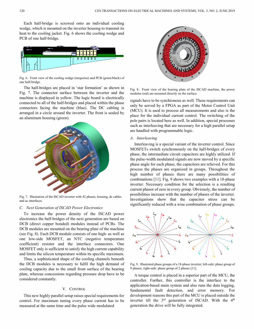
C. Next Generation of ISCAD Power Electronics To increase the power density of the ISCAD power
electronics the half-bridges of the next generation are based on DCB (direct copper bonded) modules instead of PCBs. The DCB modules are mounted on the bearing plate of the machine (see Fig. 8). Each DCB module consists of one high- as well as one low-side MOSFET, an NTC (negative temperature coefficient) resistor and the interface connectors. One MOSFET only is sufficient to satisfy the high current capability and limits the silicon temperature within its specific maximum.
Thus, a sophisticated shape of the cooling channels beneath the DCB modules is necessary to fulfil the high demand of cooling capacity due to the small front surface of the bearing plate, whereas concessions regarding pressure drop have to be considered constantly.
V. CONTROL This new highly parallel setup raises special requirements for
control. For maximum tuning every phase current has to be measured at the same time and the pulse wide modulated
Fig. 8. Front view of the bearing plate of the ISCAD machine, the power modules (red) are mounted directly on the surface.
signals have to be synchronous as well. These requirements can only be served by a FPGA as part of the Motor Control Unit (MCU). It is used to process all measurements and also is the place for the individual current control. The switching of the pole pairs is located here as well. In addition, special processes such as interleaving that are necessary for a high parallel setup are handled with programmable logic.
A. Interleaving Interleaving is a special variant of the inverter control. Since
MOSFETs switch synchronously on the half-bridges of every phase, the intermediate circuit capacitors are highly utilized. If the pulse-width modulated signals are now moved by a specific phase angle for each phase, the capacitors are relieved. For this process the phases are organized in groups. Throughout the high number of phases there are many possibilities of combinations [11]. Fig. 9 shows two examples with a 18-phase inverter. Necessary condition for the selection is a resulting current phasor of zero in every group. Obviously, the number of possibilities increase with the number of phases of the inverter. Investigations show that the capacitor stress can be significantly reduced with a wise combination of phase groups.
Fig. 9. Illustrated phase groups of a 18-phase inverter; left-side: phase group of 9 phases; right-side: phase group of 2 phases [11].
A torque control is placed in a superior part of the MCU, the controller. Further, this controller is the interface to the application-based main system and also runs the data logging, fundamental fault detection, and error memory. For development reasons this part of the MCU is placed outside the inverter till the 3rd generation of ISCAD. With the 4th generation the drive will be fully integrated.
RUNDE et al.: ISCAD – DESIGN, CONTROL AND CAR INTEGRATION OF A 48 VOLT HIGH PERFORMANCE DRIVE 121
VI. 48 VOLT BATTERY The cell configuration of common 400 V battery packs
includes a series connection of almost 100 cells. In contrast, a significantly lower number of 12 to 16 cells connected in series is necessary to achieve a nominal battery voltage of 48 V. Consequently, the number of cells connected in parallel is increased for the same energy content. Considering this, the same load current occurs for both HV and 48 V battery on cell level. The highly parallel setup yields to some advantages in comparison to a conventional HV battery pack. The relative deviation of a cell module, which is a parallel connection of cells, decreases with rising number of cells connected in parallel (law of large numbers). Due to the lower capacity deviation of modules connected in series the balancing effort is reduced.
In addition, the fault tolerance is significantly higher since a damaged cell in a parallel setup does not have as much impact as a serial setup. An increased energy per cycle by around two percent and therefore an increased service life time are two more benefits detected in the comparison to a conventional traction battery.
Furthermore, the battery pack voltage and accordingly also the voltage between two arbitrary battery cells is always lower than 60 V. Due to this fact multi-cell balancing chips that communicate over a certain potential difference are not necessary. Thus, the costs of a 48 V balancing system can be reduced clearly in comparison to a HV battery.
VII. SYSTEM SUMMARY Machine, inverter, and MCU form the integrated ISCAD
system. Only exception is the central controller until the 3rd generation. The resulting parameters of the drive are shown in Table II.
TABLE II PARAMETERS OF THE INTEGRATED ISCAD SYSTEM
Parameter Value Motor Type ISCAD induction machine Peak Power 110 kW Continuous power 55 kW Max. Torque 240 Nm Max. Speed 11500 rpm Voltage 48 V Number of Phases 42 Dimensions 35 cm diameter, 46.5 cm length Mass 70 kg Cooling System Water / Glycol
This structure allows for performance classes from 30 kW to
300 kW since the drive is scalable over the length and the number of phases. The possible applications reach from industrial machines to electromobility.
VIII. DEMONSTRATOR CAR In order to demonstrate advantages and functionality of the
48 V traction system ISCAD, a prototype vehicle was set up, based on a Geely Emgrand EV. Therefore, the existing HV
drivetrain was replaced by an ISCAD prototype of the 3rd generation. Since both drives have similar characteristic values looking at the rated and maximum power as well as the installation space, the replacement and comparison is simplified. Both drives consist of the electrical machine, power electronics, power net, battery, and MCU. The Car is shown in Fig. 10.
Fig. 10. Volabo demonstrator car with 110 kW ISCAD prototype of the 3rd generation inside (former Geely Emgrand EV).
After the first proof of concept in a car in 2018, this is the first high performance vehicle on a safe-to-touch voltage level of 48 Volt with full functionality.
A. Drive Integration The 48 V drive is placed on the front axle. The gearbox stays
the same and provides a fixed gear ratio of 7.4. As the power electronics unit of ISCAD is integrated into the drive, the space in the upper motor compartment can be used for control unit, on-board charger (OBC), and DC/DC-converter. The upper motor compartment is shown in Fig. 11.
A short length of the DC-cable is important in order to reduce the cross section and thus reduce weight and costs. The battery is placed in the underfloor of the car. This enables a short distance between battery and drive component of only round about one meter. A cross section of less than 400 mm² is sufficient to achieve low losses in the DC-cable. In future systems, a coaxial or coplanar design of the DC-cable is aspired. This eliminates the magnetic field outside of the conductor. The DC-supply in the demonstrator car is built with conventional components. The supply is divided in several single cables with a lower cross section of 50 mm² each. The drive component including gearbox and DC-cables is shown in Fig. 12.
Fig. 11. Upper motor compartment including control unit, OBC, and DC/DC-converter. The drive is implemented below.
122 CES TRANSACTIONS ON ELECTRICAL MACHINES AND SYSTEMS, VOL. 3, NO. 2, JUNE 2019
Fig. 12. Drive component (from left to right: gearbox, electrical machine, power electronics) including DC-cables.
An additional vehicle control unit (VCU) is added to the vehicle. The VCU emulates the CAN communication of all dismounted components of the HV drivetrain. Thus, remaining vehicle components (e.g. electric power steering or brake system) can be used for vehicle operation. Furthermore, the VCU records the driver’s demand and transforms it into a torque request to the drive component. Additional sensors (voltage, current, temperature) are read by the VCU and accruing data is recorded.
B. 48 V Traction Battery The HV battery in the underfloor of the car is replaced by a
48 V traction battery. To maximize safety in the prototype phase, lithium iron phosphate cells are used and reduced energy density is accepted. One battery string comprises 15 cell modules connected in series to achieve a nominal voltage of 49.5 V. One cell module consists of four parallel cells. This makes 60 cells per string. The whole battery is divided into three battery strings which are connected in parallel. Thus, the maximum string current is low enough to use common components for the disconnect switch, fuse, and current sensor, which are already available on the market. Solid state switches are used as circuit breakers and ensure an ultra-short reaction time. A battery management system with one master and two slave chips takes care of a safe operation. 15 cell voltages per string can be balanced without the need of isolated communication between several balancing chips, which are mandatory in a HV battery. A model of the battery pack is shown in Fig. 13. The different battery strings are displayed in different colors.
Fig. 13. Model of the battery pack of the demonstrator car (The three different strings are displayed in different colors). The three strings are connected in parallel.
C. Operation First, the operation of the drive is tested on a testbench.
Therefore, a load machine provides a counter torque and emulates a vehicle behaviour. The results of the testbench operation are the basis of comprehensive implementations of measures for safe operation. The reason is the safe limitation of the testbench power source, which is not available using a battery in the vehicle. The testbench is supplied by a powerful electronic DC sink and source. Thus, the closed loop control and the behaviour in case of errors can be tested.
In the following step the drive is taken into operation inside the vehicle. The drive operation is similar to the testbench. However, electric drives usually don’t have a torque sensor. The estimated torque for the closed loop control is calculated by an observer model. The VCU is connected to the remaining CAN bus of the car. Getting this connection working fault-free is often a challenging task. After a successful implementation of this connection, the control panels in the driver’s area get back their old functionality with regard to the new ISCAD.
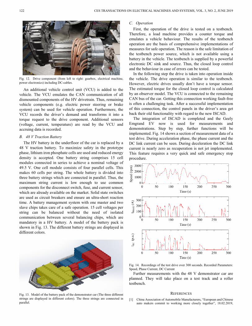
The integration of ISCAD is completed and the Geely Emgrand EV now is used for measurements and demonstrations. Step by step, further functions will be implemented. Fig. 14 shows a section of measurement data of a test drive. During acceleration phase, the phase current and the DC link current can be seen. During deceleration the DC link current is nearly zero as recuperation is not jet implemented. This feature requires a very quick and safe emergency stop procedure.
Fig. 14. Recordings of the test drive over 300 seconds. Recorded Parameters: Speed, Phase Current, DC Current
Further measurements with the 48 V demonstrator car are planned. They will take place on a test track and a roller testbench.
REFERENCES [1] China Association of Automobile Manufacturers, “European and Chinese
auto makers commit to working more closely together”, 18.02.2019,
RUNDE et al.: ISCAD – DESIGN, CONTROL AND CAR INTEGRATION OF A 48 VOLT HIGH PERFORMANCE DRIVE 123
http://www.caam.org.cn/News/20190218/0905221491.html. [2] M. Campbell; Tian Ying, Bloomberg Businessweek, “China Is Leading
the World to an Electric Car Future,” 15.11.2018, https://www.bloomberg.com/hyperdrive.
[3] C. Curry, Bloomberg New Energy Finance, “Lithium-ion Battery Costs and Market,” BNEF-Report, 05.07.2017.
[4] Wilson, T.G.; Trickey, P.H.: “D-C machine with solid-state commutation,” Electrical Engineering, vol. 81, no. 11, pp. 879-884, 1962.
[5] D. Gerling: “ISCAD – High Power Traction Drives at 48V”, in Proc, Electric Drives Production Conference 2017 (EDPC), Würzburg, Germany.
[6] A. Patzak, F. Bachheibl, A. Baumgardt, G. Dajaku, D. Gerling, “ISCAD – Electric High Performance Drive for Individual Mobility at Extra-Low Voltages”, SAE International Journal of Alternative Powertrains 5, vol. 2016-01-1179, pp. 148-156, 2016.
[7] G. Dajaku; D. Gerling: “Low Costs and High Efficiency Asynchronous Machine with Stator Cage Winding,” in Proc. IEEE International Electric Vehicle Conference (IEVC), 17.-19. December 2014, Florence, Italy.
[8] B. Rubey and D. Gerling, "Design of high current low voltage half-bridges for multi-phase inverter application in the ISCAD drive," in Proc. 2016 19th International Conference on Electrical Machines and Systems (ICEMS), 2016, pp. 1-6.
[9] A. Patzak and D. Gerling, "Design of a multi-phase inverter for low voltage high power electric vehicles," in Electric Vehicle Conference (IEVC), 2014 IEEE International, 2014, pp. 1-7.
[10] B. Rubey, A. Patzak, F. Bachheibl, D. Gerling, “Highly Efficient Integrated Low-Voltage Multi-Phase Inverter, for ISCAD Application,” in Proc. 2018 IEEE European Conference on Power Electronics and Applications (EPE/ECCE Europe), 2018, pp. 1-10.
[11] B. Rubey, A. Patzak, F. Bachheibl, D. Gerling, „DC-Link Current Harmonics Minimization in ISCAD Multi-Phase Inverters with Interleaving”, in Proc. 2017 IEEE Vehicle Power and Propulsion Conference (VPPC), 2017, pp. 1-7.
Stephan Runde was born in Steinfurt, Germany, in 1993. He attended the technical University of Dortmund and graduated with a master’s degree in electrical engineering and information technology, focusing on robotic and automotive. He is with the volabo GmbH for about two years now, working as an
embedded system engineer. Since 2017 he is responsible for the FPGA Development and beyond part of the Drive Control Team.
Andreas Baumgardt was born in Munich, Germany, in 1987. He received the M.Sc. and Ph.D. degrees in Mathematical and Electrical Engineering from the Universitaet der Bundeswehr Muenchen in 2011 and 2018. His focus lies on power electronics and battery on system level. Since 2016 he works as head of drive
control in the volabo GmbH in the field of low voltage high power traction.
Oleg Moros was born in 1984. He received the Master’s degree in Mathematical Engineering and Ph.D. degrees in electrical engineering from the Universitaet der Bundeswehr Muenchen, Germany, in 2011 and 2018, respectively. From 2012 to 2016, he was with FEAAM GmbH, Neubiberg, Germany, as a
Research Scientist. Since 2016, he has been motor developer with volabo GmbH, Ottobrunn, Germany.
Benjamin Rubey was born in 1987 in Munich, Germany. He obtained his M.Sc. degree in Electrical Engineering from the Technical University of Munich (TUM) in 2012. Between 2013 and 2015 he worked at gigatronik GmbH and was responsible for securing the electrical drivetrain of plug-in hybrid cars. Afterwards he switched to
FEAAM GmbH as a research assistant in cooperation with the Institute of Electrical Drives and Actuators for the development of low-voltage inverter topologies in 2015. Currently he works as a developer of power electronics in respect to packaging, safety, cooling and system integration at volabo GmbH since 2016.
Dieter Gerling (M’01) was born in 1961. He received the Diploma and Ph.D. degrees in electrical engineering from the Technical University of Aachen, Germany, in 1986 and 1992, respectively. From 1986 to 1999, he was with Philips Research Laboratories, Aachen, Germany, as a Research Scientist and later as a Senior Scientist. In 1999, he
joined Robert Bosch GmbH, Bühl, Germany, as Director. Since 2001, he has been Full Professor and Head of the Institute of Electrical Drives, Universitaet der Bundeswehr Muenchen, Neubiberg, Germany.