Disclosure to Promote the Right To Information Whereas the Parliament of India has set out to provide a practical regime of right to information for citizens to secure access to information under the control of public authorities, in order to promote transparency and accountability in the working of every public authority, and whereas the attached publication of the Bureau of Indian Standards is of particular interest to the public, particularly disadvantaged communities and those engaged in the pursuit of education and knowledge, the attached public safety standard is made available to promote the timely dissemination of this information in an accurate manner to the public. इंटरनेट मानक “!ान $ एक न’ भारत का +नम-ण” Satyanarayan Gangaram Pitroda “Invent a New India Using Knowledge” “प0रा1 को छोड न’ 5 तरफ” Jawaharlal Nehru “Step Out From the Old to the New” “जान1 का अ+धकार, जी1 का अ+धकार” Mazdoor Kisan Shakti Sangathan “The Right to Information, The Right to Live” “!ान एक ऐसा खजाना > जो कभी च0राया नहB जा सकता ह ै” Bhartṛhari—Nītiśatakam “Knowledge is such a treasure which cannot be stolen” IS/IEC 60898-2 (2003): Electrical accessories - Circuit-breakers for overcurrent protection for household and similar installations, Part 2: Circuit-breakers for ac and dc operation [ETD 7: Low Voltage Switchgear and Controlgear]
Transcript
Disclosure to Promote the Right To Information
Whereas the Parliament of India has set out to provide a practical regime of right to information for citizens to secure access to information under the control of public authorities, in order to promote transparency and accountability in the working of every public authority, and whereas the attached publication of the Bureau of Indian Standards is of particular interest to the public, particularly disadvantaged communities and those engaged in the pursuit of education and knowledge, the attached public safety standard is made available to promote the timely dissemination of this information in an accurate manner to the public.
इंटरनेट मानक
“!ान $ एक न' भारत का +नम-ण”Satyanarayan Gangaram Pitroda
“Invent a New India Using Knowledge”
“प0रा1 को छोड न' 5 तरफ”Jawaharlal Nehru
“Step Out From the Old to the New”
“जान1 का अ+धकार, जी1 का अ+धकार”Mazdoor Kisan Shakti Sangathan
“The Right to Information, The Right to Live”
“!ान एक ऐसा खजाना > जो कभी च0राया नहB जा सकता है”Bhartṛhari—Nītiśatakam
“Knowledge is such a treasure which cannot be stolen”
“Invent a New India Using Knowledge”
है”ह”ह
IS/IEC 60898-2 (2003): Electrical accessories -Circuit-breakers for overcurrent protection for householdand similar installations, Part 2: Circuit-breakers for acand dc operation [ETD 7: Low Voltage Switchgear andControlgear]
lS/lEC 60898-2:2003(Superseding IS 8828: 1996)
W’?i+kTmw
m wFmv--w&!qJfkTFT-Frawl-da5raq
$1-P-r2 RTmmTR13tk RKmlam Tmra5RfqqR’ tT2TRi7ilGm
Indian Standard
ELECTRICAL ACCESSORIES — CIRCUIT-BREAKERSFOR OVERCURRENT PROTECTION FOR
HOUSEHOLD AND SIMILAR INSTALLATIONS
PART 2 CIRCUIT-BREAKERS FOR ac AND dc OPERATION
ICS 29.120.50
@ BIS 2007
BUREAU OF INDIAN STANDARDSMANAK BHAVAN, 9 BAHADUR SHAH ZAFAR MARG
NEW DELHI 110002
September 2007 Price Group 7
Low-Voltage Switchgear and Controlgear Sectional Committee, ET 07
NATIONAL FOREWORD
This Indian Standard (Part 2) which is identical with IEC 60898-2 : 2003 ‘Circuit-breakers forovercurrent protection for household and similar installations: Part 2 Circuit-breakers for a.c. and d.c.operation’ issued by the International Electrotechnical Commission (lEC) was adopted by the Bureauof Indian Standards on the recommendation of the Low-Voltage Switchgear and Controlgear SectionalCommittee and approval of the Electrotechnical Division Council.
This standard is a part of the following series of standards which supersedes IS 8828 : 1996‘Electrical accessories — Circuit-breakers for overcurrent protection for household and similarinstallations’:
lS/1EC 60898-1 : 2003 Electrical accessories — Circuit-breakers for overcurrent protection forhousehold and similar installations: Part 1 Circuit-breakers for a.c. operation
1S/1EC 60898-2 : 2003 Electrical accessories — Circuit-breakers for overcurrent protection forhousehold and similar installations: Part 2 Circuit-breakers for a.c. and d.c. operation
This standard is to be read in conjunction with lS/lEC 60898-1 : 2003 ‘Electrical accessories —Circuit-breakers for overcurrent protection for household and similar installations: Part 1 Circuit-breakers for a.c. operation’.
The text ofdeviations.Standards,
a)
b)
IEC Standard has been approved as suitable for publication as an Indian Standard withoutCertain terminology and conventions are, however, not identical to those used in Indian
Attention is particularly drawn to the following:
Wherever the words ‘International Standard’ appear referring to this standard, they shouldbe read as ‘Indian Standard’.
Comma (,) has been used as a decimal marker, while in Indian Standards, the currentpractice is to use a point (.) as the decimal marker.
Only the English text of the International Standard has been retained while adopting it as an IndianStandard, and as such the page numbers given here are not the same as in the IEC Publication.
For the purpose of deciding whether a particular requirement of this standard is complied with, thefinal value, observed or calculated, expressing the result of a test or analysis, shall be rounded off inaccordance with IS 2 : 1960 ‘Rules for rounding off numerical values (revised). The number ofsignificant places retained in the rounded off value should be same as that of the specified value inthis standard.
lS/lEC 60898-2:2003
Indian Standard
ELECTRICAL ACCESSORIES — CIRCUIT-BREAKERSFOR OVERCURRENT PROTECTION FOR
HOUSEHOLD AND SIMILAR INSTALLATIONSPART 2 CIRCUIT-BREAKERS FOR ac AND dc OPERATION
1 Scope and object
This clause of Part 1 is applicable except as follows:
Addition at the end of the first paragraph:
This standard gives additional requirements for single- and two-pole circuit-breakers which, inaddition to the above characteristics, are suitable for operation with direct current, and have arated d.c. voltage not exceeding 220 V for single-pole and 440 V for two-pole circuit-breakers,a rated current not exceeding 125 A and a rated d.c. short-circuit capacity not exceeding10000 A.
NOTE This standard applies to circuit-breakers able to make and break both a.c. current and d.c. current.
Delete the last two paragraphs.
2 Normative references
This clause of Part 1 applies.
Delete IEC 61009-1:1991, IEC 61009-2-1:1991 and IEC 61009-2-2:1991.
3 Definitions
Clause 3 of Part 1
Addition:
3.5.10.3time constant
applies with the following modification:
the rise time T = UR (ins) of a prospective direct current to reach a value of 0,63 times themaximum peak current
lS/lEC 60898-2:2003
4 Classification
Clause 4 of Part 1 applies with the following modifications:
4.1 According to the number of poles
Replacement:
single-pole circuit-breakers;
– two-pole circuit-breakers with two protected poles.
4.5 According to the instantaneous tripping current (see 3.5.17)
Deiete D-Type.
Addition:
4.7 According to the time constant
– Circuit-breakers suitable for d.c. circuits with a time constant of T <4 ms.
Circuit-breakers suitable for d.c. circuits with a time constant of T< 15 ms.
NOTE It is assumed that short-circuit currents of 1 500 A are not axceeded in installations in which, due to theloads connected, time constants in normal service up to 15 ms can occur. Where higher short-circuit currents mayoccur, the time constant of T = 4 ms is considered sufficient.
5 Characteristics of circuit-breakers
Clause 5 applies with the following modification:
5.3.1 Preferred values of rated voltage
Replacement:
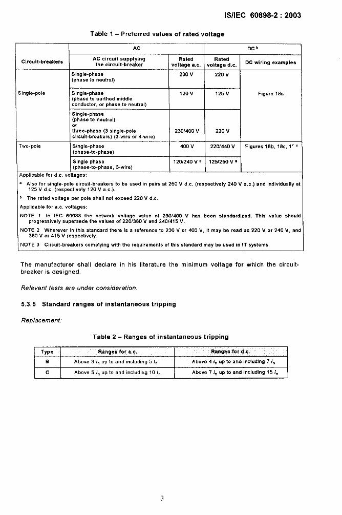
The preferred values of rated voltages are given in table 1
Examples of connections of circuit-breakers in d.c. systems are given in figure 18
<
IWEC 60898-2:2003
Tablel -Preferred values of rated voltage
AC Dc b—
Circuit-breakersAC circuit supplying Rated Rated
the circuit-breaker voltage a.c. voltage d.c. DC wiring examples
Single-phase 230 V 220 v(phase to neutral)
Single-pole Single-phase 120V 125V Figure 18a(phase to earthed middleconductor, or phase to neutral)
Single-phase(phase to neutral)orthree-phase (3 single-pole 2301400 V 220 vcircuit-breakars) (3-wire or 4-wire)
Two-pole Single-phase 400 v 2201440 V Figures 18b, 18c, 1” +(phase-to-phase)
Single phase 1201240 V a 125/250 V a(phase-to-phase, 3-wire)
Applicable for d.c. voltages:
a ALSO for single-pole circuit-breakers to be used in pairs at 250 V d.c. (respectively 240 V a.c.) and individually at125 V d,c. (respectively 120 V a.c.).
b The rated voltage per pole shall not exceed 220 V d.c,
Applicable for a,c. voltages:
NOTE 1 In IEC 60036 the network voltage valua of 230/400 V has bean standardized. This value shouldprogressively supersede the values of 220/380 V and 240/415 V.
NOTE 2 Wherever in this standard there is a reference to 230 V or 400 V, it may be read as 220 V or 240 V, and380 V or 415 V respectively.
NOTE 3 Circuit-breakers complying with the requirements of this standard may be used in IT systems.
The manufacturer shall declare in his literature the minimum voltage for which the circuit-breaker is designed.
Relevant fasts are undar consideration.
5.3.5 Standard ranges of instantaneous tripping
Replacement:
Table 2- Ranges of instantaneous tripping
[Type Ranges for a.c.
1Ranges for d.c.
I B I Above 3 /. up to and including !5 In I Above 4 In up to and including 7 In II 1
I c Above 5 In up to and including 10 In Above 7 In up to and including 15 In
lS/lEC 60898-2:2003
6 Marking and other product information
Clause 6 of Part 1 applies with the following modifications:
Replacement:
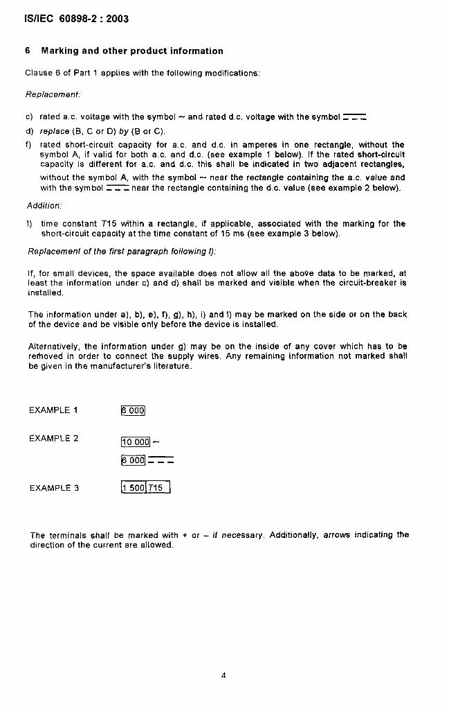
c) rated a.c. voltage with the symbol - and rated d.c. voltage with the symbol ~_
d) rep/ace (B, C or D) by (B or C),
f) rated short-circuit capacity for a.c. and d.c. in amperes in one rectangle, without thesymbol A, if valid for both a.c. and d.c. (see example 1 below). If the rated short-circuitcapacity is different for a.c. and d.c. this shall be indicated in two adjacent rectangles,
without the symbol A, with the symbol - near the rectangle containing the a.c. value andwith the symbol = - near the rectangle containing the d.c. value (see example 2 below).
Addition:
1) time constant T15 within a rectangle, if applicable, associated with the marking for theshort-circuit capacity at the time constant of 15 ms (see example 3 below).
Replacement of the first paragraph following /):
If, for small devices, the space available does not allow all the above data to be marked, atleast the information under c) and d) shall be marked and visible when the circuit-breaker isinstalled.
The information under a), b), e), f), g), h), i) and 1) may be marked on the side or on the backof the device and be visible only before the device is installed.
Alternatively, the information under g) may be on the inside of any cover which has to bererhoved in order to connect the supply wires. Any remaining information not marked shallbe given in the manufacturer’s literature.
EXAMPLE 1 mEXAMPLE 2
m“
m===EXAMPLE 3 m
The terminals shall be marked with + or - if necessary. Additionally, arrows indicating thedirection of the current are allowed.
lS/lEC 60898-2:2003
7 Standard conditions for operation in service
Clause 7 of Part 1 applies.
8 Requirements for construction and operation
Clause 8 of Part 1 applies with the following modifications:
8.6.1 Standard time-current zone
Replacement:
Testrest Type current
a.c.
a B, c 1,13/”
b B, C 1,45 In
Table 7- Time-current operating characteristics
Test Initial Limits Resultcurrent condition of tripping or to be
d.c. non-tripping time obtained
Cold” t21h(ln S63A) NO tripping
t22h(/n> 63A)
Immediately tclh(ln <63A) Trippingfollowing t<2h(/n> 63A)test a
c B, c 2,55 In Cold* ls<tc60s(/ns 32A) Tripping
lS<t<120S(/n> 32A)
d B 3 In 4 In Cold* 0,1<t<45s(/n <32A) Tripping
0,1<tc90s(ln> 32A)c 5 \“ 7 In 0,1< t<i5S(/n S32A)
0,1< f<30s(/n> 32A)
e B 5 In 7 I“ Cold* t<o,lsc
Tripping
10/” 15/”
“ The term “cold” means without previous loading, at the reference calibration temperature.
=
Remarks
=1Current steadilyIncreased~ithin 5 s
Currentestablished byclosing anauxiliary switch
=1Currentestablished byclosing anauxiliary switch
8.8 Performance at short-circuit currents
Replacement of the third paragraph:
It is required that circuit-breakers be able to make and to break any value of current up to andincluding the value corresponding to the rated short-circuit capacity at rated frequency, at apower-frequency recovery voltaga equal to 105 % (d5 %) of the rated operational voltage andat any power factor not less or any time constant not greater than the appropriate limit of therange stated in 9. 12.5; it is also requirad that the corresponding values of 12t lie below the 12tcharacteristic (see 3.5. 13).
IWEC 60898-2:2003
9 Tests
Clause 9 of Part 1 applies with the following modifications:
9.1 Type tests and test sequences
Replacement of the first paragraph of 9.1.2.
The test sequences and the number of samples to be submitted are stated in annex C of thisstandard.
9.1.1
Replacement of the second paragraph after table 8:
The test sequences and the number of samples to be submitted are stated in annex C of thisstandard.
9.10.2 Test of instantaneous tripping and of correct opening of the contacts
Replacement:
9.10.2.2 For circuit-breakers of the B-type
An alternating current equal to 3 In is passed through all poles, starting from cold. The
opening time shall be not less than O,1 s and not more than:
– 45 s for rated currents up to and including 32A;
– 90 s for rated currents above 32 A.
An alternating current equal to 5 In is then passed through all poles, starting from cold.
The circuit-breaker shall trip in a time less than 0,1 s.
A direct current equal to 4 In is passed through all poles, starting from cold.
The opening time shall be not less than 0,1 s and not more than:
– 45 s for rated currents up to and including 32 A;
– 90 s for rated currents above 32 A.
A direct current equal to 7 In is then passed through all poles, starting from cold.
The circuit-breaker shall trip in a time less than 0,1 s.
9.10.2.3 For circuit-breakers of the C-type
An alternating current equal to 5 In is passed through all poles, starting from cold.
The opening time sha// be not less than 0,7 s and not more than:
— 15 s for rated currents up to and including 32 A;
— 30 s for ratad currents above 32 A.
An alternating current equal to 10 In is then passed through all poles, starting from cold
The circuit-breaker shall trip in a time less than 0,1 s.
6
ISIIEC 60898-2:2003
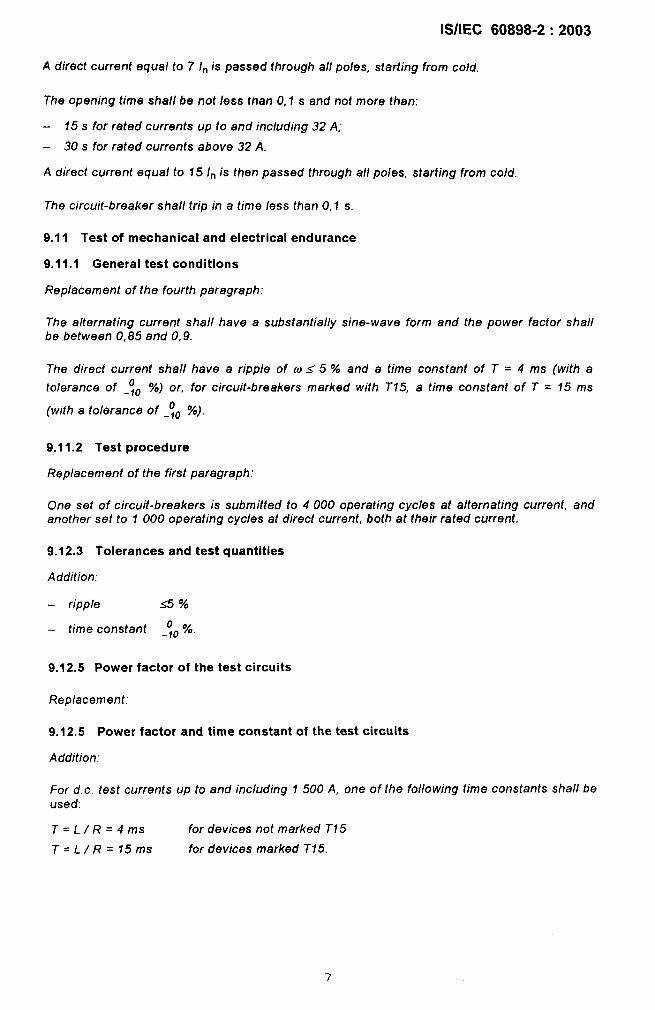
A direct current equal to 7 In is passed through all poles, starting from cold.
The opaning time shall be not less tnan 0,1 s and not more than:
– 15 s for rated currents up to and including 32 A;
– 30 s for rated currents above 32A.
A direct current equal to f 5 In is then pass ad through all poles, starting from cold.
The circuit-breaker sha/1 trip in a time less than 0,1 s.
9.11 Test of mechanical and electrical endurance
9.11.1 General test conditions
Replacement of the fourth paragraph:
The alternating current shall have a substantially sine-wave form and the power factor shallbe between 0,85 and 0,9.
The direct current shall have a ripple of ms 5 % and a time constant of T = 4 ms (with a
0 %) or for circuit-breakers marked with T15, a time constant of T = 15 mstolerance of _,. ,
(with a tolerance of _~o %).
9.11.2 Test procedure
Replacement of the first paragraph:
One set of circuit-breakers is submitted to 4000 operating cycles at alternating current, andanother set to 1 000 operating cycles at direct current, both at their rated current.
9.12.3 Tolerances and test quantities
Addition.”
– ripple -a %
0 Yo.– time constant _fo
9.12.5 Power factor of the test circuits
Replacement:
9.12.5 Power factor and time constant of the test circuits
Addition:
For d. c. test currents up to and including 1500 A, one of the folio wing time constants shall beused:
T= L/ R=4ms for devices not marked T15
T= L/ R=15ms for devices marked T15.
lS/lEC 60898-2:2003
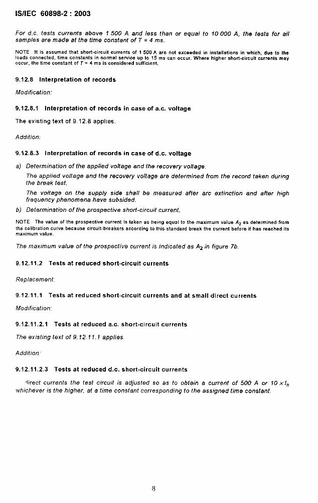
For d. c. tests currents above 1500 A and less than or equal to 10000 A, the tests for allsamples are made at the time constant of T = 4 ms.
NOTE It is assumed that short-circuit currents of 1 500A are not exceeded in installations in which, due to theloads connacted, time constants in normal service up to 15 ms can occur. Where higher short-circuit currents meyoccur, the time constant of T = 4 ms is considered sufficient.
9.12.8 Interpretation of records
Modification:
9.12.8.1 Interpretation of records in case of a.c. voltage
The existing text of 9.12.8 applies,
Addition:
9.12.8.3 interpretation of records in case of d.c. voltage
a) Determination of the applied voltage and the recovery voltage.
The applied voltage and the recovery voltage are determined from the record taken duringthe break test.
The voltage on the supply side shall be measured after arc extinction and after highfrequency phenomena have subsided.
b) Determination of the prospective short-circuit current.
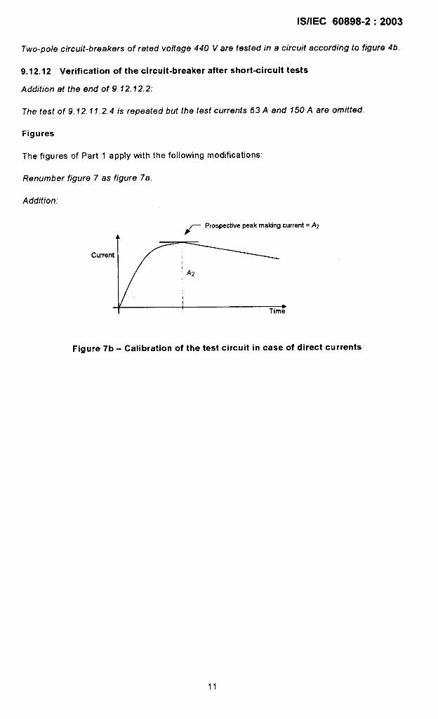
NOTE The value of the prospective current is taken as being equal to the maximum valua A2 as determined from
the calibration curve because circuit-breakers according to this standard break the current before it has reached itsmaximum valua.
The maximum value of the prospective current is indicated as A2 in figure 7b.
9.12.11.2 Tests at reduced short-circuit currents
Replacement:
9.12.11.1 Tests at reduced short-circuit currents and at small direct currents
Modification:
9.12.11 .2.1 Tests at reduced a.c. short-circuit currents
The existing text of 9.12.11.1 applies.
Addition:
9.12.11 .2.3 Tests at reduced d.c. short-circuit currents
~irect currents the test circuit is adjusted so as to obtain a current of 500 A or 10 x/n
whichever is the higher, at a time constant corresponding to the assigned time constant.
8
lS/lEC 60898-2:2003
Each of the protected poles of the circuit-breaker is subjected separately to a test in a circuit,of which the connections are shown in figure 3.
The circuit-breaker is caused to open automatically three times, the circuit being closed onceby the auxiliary switch A and twice by the circuit-breaker itself.
The sequence of operations shall be;
o–t-co-t–co
After arc extinction, the recovery voltage shall be maintained for a duration not less than0,1 s.
9.12.11.2.4 Test at small direct currents up to and including 150 A
The circuit-breaker shall be closed three times on to each of the test currents listed below;during the tests the operating means is actuated as in normal use. If the circuit-breaker doesnot trip, it shall be switched off manually.
Test currents: 1 A, 2 A, 4 A, 8 A, 16 A, 32A, 63A, 150A
The time between each operating cycle CO shall be at least 10s, the closing time shall not belonger than 2s. The time betwean the various test currents shall be at least 2 min.
The time of the arc extinction during the test shall not exceed 1 s.
9.12.11.3 Testatl 500A
Replacement of the first paragraph:
For circuit-breakers having rated short-circuit capacity of 1500 A, the test circuit is calibratedaccording to 9.12.7.1 and 9.12.7.2, to obtain a current of 1 500 A at a power factorcorresponding to this current according to table 17.
For direct current the time constant is calibrated corresponding to the assigned time constant.
Replacement of the second paragraph:
For circuit-breakers having rated short-circuit capacity exceeding 1500 A, the tast circuit iscalibrated according to 9.12.7.1 and 9.12.7.3, at a power factor corresponding to 1500 A,according to table 17.
For direct current the time constant is calibrated corresponding to the assigned time constant.
Replace the eleventh paragraph:
The sequence of operations shall be as specified in 9.12.11.2.1 and 9.12.11.2.3.
For single-pole circuit-breakers of rated voltage 230/400 V the operations for a. c. are asfollows:
CJ
lS/lEC 60898-2:2003
Subsequent to the six O operations on/y two CO operations are performed. In addifion, thesecircuit-breakers are then tested by performing simultaneously one O operation, with onecircuit-breaker being inserted in each phase of the test circuit for three-pole circuit-breakers(see figure 5). For this test the auxiliary switch establishing the short-circuit is notsynchronized.
For the tests at d. c.
single-pole circuit-breakers of rated voltage 220 V are tested in a circuit according tofigure 3;
– two-pole circuit-breakers of rated voltage 440 V are tested in a circuit according tofigure 4b.
9.12.11 .4.2 Test at service short-circuit capacity (/=,)
Replacement of the first paragraph of a).
a) The test circuit is calibrated according to 9.12.7.1 and 9.12.7.3, on a.c. with a power factoraccording to table 17, or on d.c. with a time constant according to 9.12.5.
Addition:
e) In the case of direct current, the test saquence for single- and two-pole circuit-breakers is:
o-t-co-t-co
Three operations are made, the circuit being closed once by the auxiliary switch A and twiceby the circuit-breaker.
Single-pole circuit-breakers of rated voltage 220 V are tested in a circuit according to figure 3.
Two-pole circuit-breakers of rated voltage 440 V are tested in a circuit according to figure 4b.
2.11 .4.3 Test at rated short-circuit capacity (Icn)
Replacement of the first paragraph:
a) The test circuit is calibrated according to 9. 12.7.1 and 9.12.7.2, on a. c. with a power factoraccording to table 17, on d.c. with a time constant according to 9.12.5.
Addition.”
c) In the case of direct current, the test sequence for single- and two-pole circuit-breakers is:
o-t-co
Two operations are made, the circuit being closed once by the auxi/iary switch A and once bythe circuit-breaker.
Single-pole circuit-breakers of rated voltage 220 V are tested in a circuit according to figure 3.
10
lS/lEC 60898-2:2003
Two-pole circuit-breakers of rated voltage 440 V are tested in a circuit according to figure 4b.
9.12.12 Verification of the circuit-breaker after short-circuit tests
Addition at the end of 9.12.12.2:
The test of 9,12. f 1.2.4 is repeated but the test currents 63A and f50 A are omitted.
Figures
The figures of Part 1 apply with the following modifications:
Renumber figure 7 as figure 7a.
Addition:
A/-
Prospective peak meting current = AZ
Current
AZ
➤Time
Figure 7b - Calibration of the test circuit in case of direct currents
11
N
Circuit-breakerrated voltage
Maximum voltagebetween theconductors
Maximum voltagebetween conductorand earth
Circuit breaker
Circuit
a
220 v 125V 1251250 V
220 v 125V 125V
220 v 125V 125V
Single-pole
r+-7
1
2@
L+ L-
b
220/440 V 250 V 1251250 V
440 v I 250 V I 250 V
+
Two-pole
L+ L-
2201440 V
440 v
440 v ‘
c
1-250 V 1251250 V
250 V 250 V
250 V “ 250 V ‘
Two-pole
‘ For applications with an earthed negative pole, where the voltage to earth is higher than the rated voltage of a single-pole circuit-breaker.
d
2201440 V 250 V 125/250 V
440 v 250 V 250 V
220 v 125V 125V
, ,
Two-pole
I +
+ I
1 3
m
2@ 4G
L+ L- M
Figure 18- Examples of connections of the circuit-breakers in different d.c. systems
lS/lEC 60898-2:2003
Annexes
The annexes of Part 1 are applicable, except as follows:
13
lS/lEC 60898-2:2003
Annex C
Annex C of Part 1 appiies with the following modifications:
Replacement:
Table C.1 - Test sequences
Clause orest sequence subclause Test (or inspection)
6 Marking
8.1,1 General
8.1.2 Mechanism
9.3 Indelibility of marking
8.1.3 Clearances and creepage distances (external parts only)
8.1,6 Non-interchangeability
9.4Reliability of screws, current-carrying parts and
A connections
9.5Reliability of screw-type terminals for external copperconductors
9.6 Protection against electric shock
8.1.3 Clearances and creepage distances (internal parts only)
9.14 Resistance to heat
9.15 Resistance to abnormal heat and to fire
9,16 Resistance to rusting
9,7 Dielectric properties and isolating capability
B 9.8 Temperature rise and power loss
9.9 28-day test
Testperformed
at
9.11 a.c. Mechanical and electrical endurance
9.12.11 .2.1 Test at reduced a.c. short-circuit currents
c,9.12.12 Verification of circuit-breaker after short-circuit tests
c 9,11 Mechanical and electrical endurance
9,12.11 .2.3 d.c. Test at reduced d.c. short-circuit currents
9.12.11 .2.4 Test at small direct currents up to and including 150A
9.12.12 Verification of circuit-breaker after short-circuit tests
9.12.11 .2.2 Short-circuit test for verifying the suitability of circuit-
C> a.c. breakers for use in IT systems
9.12.12 Verification of circuit-breaker after short-circuit tests
Do 9.10 a.c. d.c. Tripping characteristic
9.13 Mechanical stressesD
9.12.11.3 a.c. d.c. Short-circuit performance at 1 500AD,
9.12,12 Verification of circuit-breaker after short-circuit tests
9.12.11 .4,2 Service short-circuit capacity (ICJ
Et a.c. d.c.9,12.12 Verification of circuit-breaker after short-circuit tests
E9.12.11 .4.3 Performance at rated short-circuit capacity (Icn)
E, a.c. d.c.9,12.12 Verification of circuit-breaker after short-circuit tests
NOTE With the agreement of the manufacturer the same samples may be used for more than one sequence.
14
lS/lEC 60898-2:2003
Replacement:
Table C.2 - Number of samples for full test procedure
‘es’F=i=-sequence
A 1
B 3
E, 3+3~ 3
E2 3+4~ 3
Minimum number of sampleswhich shall pass Number of samples for
the tests a. brepeated tests c
1
2
2.
Ze
Ze+zd.e
2e+3d, e
a In total, a maximum of two test sequences may be repeated.
Dc AC Dc
— —
I I
3
Ze 1313Ze 3 3
2e 3 3
Ze 3+3~ 3
2e 3+4~ 3
b It is assumed that a sample which has not passed a test has not met theassembly defects which are not representative of the design.
c In the case of repeated tests, all resulfs shall be acceptable.
requirements due to workmanship
d Supplementary samples in the case of single-pole circuit-breakers of rated voltage 230/400 V.
e AH samples shall meet the test requirements of 9.12.10, 9.12.11.2, 9.12.11.3 and 9.12.11.4 as appropriate.
01
I
15
Bureau of Indian Standards
BIS is a statutory institution established under the Bureau of Indian Standards Act, fl 986 to promote
harmonious development of the activities of standardization, marking and quality certification of
goods and attending to connected matters in the country.
Copyright
BIS has the copyright of all its publications. No part of these publications may be reproduced in any
form without the prior permission in writing of BIS. This does not preclude the free use, in the course
of implementing the standard, of necessary details, such as symbols and sizes, type or grade
designations. Enquiries relating to copyright be addressed to the Director (Publications), 61S.
Review of Indian Standards
Amendments are issued to standards as the need arises on the basis of comments. Standards are
also reviewed periodically; a standard along with amendments is reaffirmed when such review indicates
that no changes are needed; if the review indicates that changes are needed, it is taken up for revision.
Users of Indian Standards should ascertain that they are in possession of the latest amendments or
edition by referring to the latest issue of ’61S Catalogue’ and ‘Standards: Monthly Additions’.
This Indian Standard has been developed from Dot: No. ET 07 (5586)
Amendments Issued Since Publication
Amend No. Date of Issue Text Affected
BUREAU OF INDIAN STANDARDS
Headquarters:
Manak Bhavan, 9 Bahadur Shah Zafar Marg, New Delhi 110002Telephones 23230131,23233375,2323 9402 website: www.bis.org.in
Regional Offices: Telephones
Central :
Eastern :
Northern :
Southern :
Western :
Branches:
Manak Bhavan, 9 Bahadur Shah Zafar Marg{
23237617NEW DELHI 110002 23233841
1/14 C.I.T. Scheme Vll M, V.I.P. Road, Kankurgachi{