Click here for an overview of the wireless components used in a typical radio transceiver. Maxim > Design Support > Technical Documents > Application Notes > Automotive > APP 5023 Maxim > Design Support > Technical Documents > Application Notes > Power-Supply Circuits > APP 5023 Maxim > Design Support > Technical Documents > Application Notes > Wireless and RF > APP 5023 Keywords: RF, ISM, transmitter, RKE, RF remote control, short range radio APPLICATION NOTE 5023 ISM Transmitter Has Constant Transmitter Power for Varying Supply Voltage Jan 09, 2012 Abstract: In battery-powered RF transmitters such as garage door openers and remote keyless entry for cars, as the battery drains, the transmit power typically falls. This application note demonstrates that combining a high-efficiency step-up, or boost, voltage converter with an ISM transmitter will keep the transmitted power constant (under 0.5dB variation) over the battery voltage range. Performance data will show that the battery life for constant transmit power is up to 2 times that of a transmitter whose power drops as the battery voltage drops. The AC voltage ripple produced by the voltage converter does not degrade the quality of the amplitude-shift keying (ASK) data link and does not violate U.S. and European radio emission standards relating to short-range radio links. Introduction Short-range transmitters are used for many applications in unlicensed ISM frequency bands such as 433.05MHz to 434.79MHz in Europe, 260MHz to 470MHz in the United States, and similar frequency ranges in parts of Asia. Most of these applications require small transmitters (e.g., automobile key fobs, garage door and gate openers, security alarm sensors) that use battery power. As a battery runs down, its voltage decreases which, in turn, reduces the radiated power of most inexpensive, low-current-drain transmitters. This depletion of radiated power happens because many short-range transmitters such as the Maxim MAX1472 use a switched amplifier for the best efficiency (See Maxim application note 3589, "Power Amplifier Theory for High-Efficiency Low-Cost ISM-Band Transmitters"), and the transmitted power of a switched amplifier decreases roughly as the square of the supply voltage. This means that a transmitter powered by a battery whose voltage drops from 3V to 1.8V over its lifetime will reduce its transmitted power to about 35% of its beginning power. In fact there will be between 4dB and 5dB of transmission power loss. This application note shows that combining a high-efficiency step-up, or boost, voltage converter (the MAX1947) with an ISM transmitter ( MAX1472 ) will keep the transmitted power constant (under 0.5dB variation) over the battery voltage range. This configuration will also reduce the battery life by no more than 15%. The article also shows that the AC-voltage ripple produced by the voltage converter does not degrade the quality of the amplitude-shift keying (ASK) data link nor does it violate U.S. and European radio emission standards for short-range radio links. The Investigation The objectives of this investigation were: Determine whether adding a voltage converter to a transmitter would maintain constant transmitter power over a typical battery voltage range. Determine the effect of the voltage converter on the overall efficiency of the transmitter system. Show the trade-off between constant transmitter power and battery life. Measure the effects of the voltage-converter AC ripple on the quality of the radio link. Evaluation (EV) kits for the transmitter and voltage converter were used to measure how well constant transmitter power and high efficiency can be achieved. The transmitter used was the MAX1472, which operates in the 300MHz to 450MHz Page 1 of 16
Transcript
Click here for an overview of the wirelesscomponents used in a typical radiotransceiver.
Keywords: RF, ISM, transmitter, RKE, RF remote control, short range radio
APPLICATION NOTE 5023
ISM Transmitter Has Constant Transmitter Power for VaryingSupply VoltageJan 09, 2012
Abstract: In battery-powered RF transmitters such as garage door openers and remote keyless entry for cars, as the batterydrains, the transmit power typically falls. This application note demonstrates that combining a high-efficiency step-up, orboost, voltage converter with an ISM transmitter will keep the transmitted power constant (under 0.5dB variation) over thebattery voltage range. Performance data will show that the battery life for constant transmit power is up to 2 times that of atransmitter whose power drops as the battery voltage drops. The AC voltage ripple produced by the voltage converter doesnot degrade the quality of the amplitude-shift keying (ASK) data link and does not violate U.S. and European radio emissionstandards relating to short-range radio links.
IntroductionShort-range transmitters are used for many applications in unlicensed ISM frequencybands such as 433.05MHz to 434.79MHz in Europe, 260MHz to 470MHz in the UnitedStates, and similar frequency ranges in parts of Asia. Most of these applications requiresmall transmitters (e.g., automobile key fobs, garage door and gate openers, securityalarm sensors) that use battery power.
As a battery runs down, its voltage decreases which, in turn, reduces the radiated powerof most inexpensive, low-current-drain transmitters. This depletion of radiated powerhappens because many short-range transmitters such as the Maxim MAX1472 use a switched amplifier for the best efficiency(See Maxim application note 3589, "Power Amplifier Theory for High-Efficiency Low-Cost ISM-Band Transmitters"), and thetransmitted power of a switched amplifier decreases roughly as the square of the supply voltage. This means that atransmitter powered by a battery whose voltage drops from 3V to 1.8V over its lifetime will reduce its transmitted power toabout 35% of its beginning power. In fact there will be between 4dB and 5dB of transmission power loss.
This application note shows that combining a high-efficiency step-up, or boost, voltage converter (the MAX1947) with an ISMtransmitter (MAX1472) will keep the transmitted power constant (under 0.5dB variation) over the battery voltage range. Thisconfiguration will also reduce the battery life by no more than 15%. The article also shows that the AC-voltage ripple producedby the voltage converter does not degrade the quality of the amplitude-shift keying (ASK) data link nor does it violate U.S.and European radio emission standards for short-range radio links.
The InvestigationThe objectives of this investigation were:
Determine whether adding a voltage converter to a transmitter would maintain constant transmitter power over a typicalbattery voltage range.Determine the effect of the voltage converter on the overall efficiency of the transmitter system.Show the trade-off between constant transmitter power and battery life.Measure the effects of the voltage-converter AC ripple on the quality of the radio link.
Evaluation (EV) kits for the transmitter and voltage converter were used to measure how well constant transmitter power andhigh efficiency can be achieved. The transmitter used was the MAX1472, which operates in the 300MHz to 450MHz
frequency range. Its supply voltage range is 2.1V to 3.6V and it typically transmits 10mW, or +10dBm while drawing about10mA of DC current from a 2.7V supply. The specific frequency used for these tests was 433.92MHz, which is permitted inboth Europe and the U.S. The voltage converter used was the MAX1947, a step-up DC-DC converter with an input (battery)voltage range of 0.7V to 3.6V. This converter uses an external inductor and capacitor with internal switching to charge theinductor, then transfer the energy to the capacitor and load resistance. The MAX1947 has factory-selected output voltages of1.8V, 2.5V, 3.0V, and 3.3V. The MAX1947ETA33 (3.3V output) was used for these measurements. For input voltages higherthan the output voltage, the MAX1947 automatically passes them with no effect.
The MAX1472EVKIT was modified by changing the passive components in its antenna-matching network to produce +10dBmof transmitter power with a 3.3V supply. Only one simple modification was made to the MAX1947EVKIT: the 1.8V output ICthat is the standard value for the kit was replaced with a 3.3V output IC. The EV kits were connected and the input voltage tothe MAX1947 (representing the battery voltage) came from a laboratory power supply with a current meter in series. Anoscilloscope, power meter, and spectrum analyzer were used to collect data in addition to the voltage and currentmeasurements.
In addition to the above combined EV kits, two other Maxim transmitter EV kits were used as performance references: aMAX1472 "Standard" EV kit that produces +10dBm of transmitter power with a 2.7V supply; and a MAX7060EVKIT, afrequency- and power-adjustable transmitter whose transmitter power is SPI programmable.
In the first set of tests, voltage, current, and transmitter power measurements were made on four different transmitterconfigurations. Power and supply current versus voltage was plotted, efficiency calculations made, and estimated effects onbattery lifetime calculated.
In the second set of tests, the ripple voltage on the MAX1947's output supply was recorded on an oscilloscope while theMAX1472 transmitter drew power from the MAX1947.
In the third set of tests the spectrum of the RF signal transmitted from the MAX1472 was recorded for the expected operatingrange of input (battery) voltages. An ASK radio link was established with a MAX7033EVKIT ASK receiver to determine theeffect of the voltage converter ripple on the link performance.
Summary of ResultsTransmitter Power vs. Battery VoltageFour power amplifier (PA) configurations were compared for their ability to maintain a steady transmitter power output with theleast amount of supply current drain. Because the supply current varies with battery voltage as the battery discharges, thecurrent drain of the configurations was compared by calculating the lifetime of a typical battery (or a set of batteries) under a100% duty-cycle current drain.
Baseline configuration: MAX1472 matched for +10dBm Tx power at 2.7V.
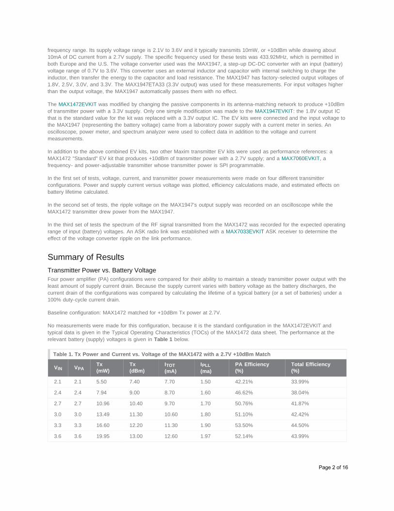
No measurements were made for this configuration, because it is the standard configuration in the MAX1472EVKIT andtypical data is given in the Typical Operating Characteristics (TOCs) of the MAX1472 data sheet. The performance at therelevant battery (supply) voltages is given in Table 1 below.
Table 1. Tx Power and Current vs. Voltage of the MAX1472 with a 2.7V +10dBm Match
Table 1 illustrates the transmitter's power variation with battery voltage that the DC-DC converter should eliminate. Thetransmitter power drops 5.6dB when the battery voltage drops from 3.6V to 2.1V, which are the maximum and minimumspecified voltages for the MAX1472. The specified Tx power of +10dBm occurs near the middle of the voltage range.Consequently, too much power is transmitted when the battery is fresh and not enough power is transmitted when the batteryis near the end of its life.
Constant Transmitter Power Using a DC-DC ConverterThis investigation will show that a step-up, or boost converter can be combined with a standard Maxim transmitter to achievea constant +10dBm transmit power. The boost converter chosen for the combination was the MAX1947 with a factory-set3.3V output. Hence, the two most commonly used batteries for portable devices (a CR2032 coin cell, two AAA batteries inseries) will have battery voltages below the converter's output voltage. If the battery voltage exceeds 3.3V, the MAX1947simply passes the voltage through.
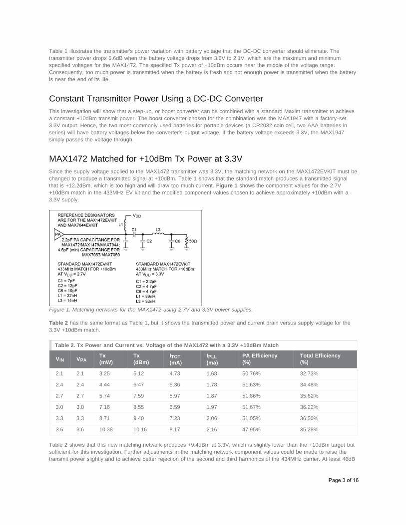
MAX1472 Matched for +10dBm Tx Power at 3.3VSince the supply voltage applied to the MAX1472 transmitter was 3.3V, the matching network on the MAX1472EVKIT must bechanged to produce a transmitted signal at +10dBm. Table 1 shows that the standard match produces a transmitted signalthat is +12.2dBm, which is too high and will draw too much current. Figure 1 shows the component values for the 2.7V+10dBm match in the 433MHz EV kit and the modified component values chosen to achieve approximately +10dBm with a3.3V supply.
Figure 1. Matching networks for the MAX1472 using 2.7V and 3.3V power supplies.
Table 2 has the same format as Table 1, but it shows the transmitted power and current drain versus supply voltage for the3.3V +10dBm match.
Table 2. Tx Power and Current vs. Voltage of the MAX1472 with a 3.3V +10dBm Match
VIN VPATx(mW)
Tx(dBm)
ITOT(mA)
IPLL(ma)
PA Efficiency(%)
Total Efficiency(%)
2.1 2.1 3.25 5.12 4.73 1.68 50.76% 32.73%
2.4 2.4 4.44 6.47 5.36 1.78 51.63% 34.48%
2.7 2.7 5.74 7.59 5.97 1.87 51.86% 35.62%
3.0 3.0 7.16 8.55 6.59 1.97 51.67% 36.22%
3.3 3.3 8.71 9.40 7.23 2.06 51.05% 36.50%
3.6 3.6 10.38 10.16 8.17 2.16 47.95% 35.28%
Table 2 shows that this new matching network produces +9.4dBm at 3.3V, which is slightly lower than the +10dBm target butsufficient for this investigation. Further adjustments in the matching network component values could be made to raise thetransmit power slightly and to achieve better rejection of the second and third harmonics of the 434MHz carrier. At least 46dB
Page 3 of 16
of harmonic rejection is needed to satisfy European emission regulations; the circuit topology of Figure 1 can achieve this withproper selection of component values.
Notice that the current drain at each supply voltage is lower than it is for the 2.7V match. Note too that the power at 2.1V isjust +5.2dBm instead of +7.4dBm for the 2.7V match. There is still about 5dB reduction in transmit power when the batteryvoltage drops from 3.6V to 2.1V.
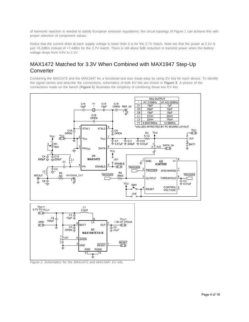
MAX1472 Matched for 3.3V When Combined with MAX1947 Step-UpConverterCombining the MAX1472 and the MAX1947 for a functional test was made easy by using EV kits for each device. To identifythe signal names and describe the connections, schematics of both EV kits are shown in Figure 2. A picture of theconnections made on the bench (Figure 3) illustrates the simplicity of combining these two EV kits.
Figure 2. Schematics for the MAX1472 and MAX1947 EV kits.
Page 4 of 16
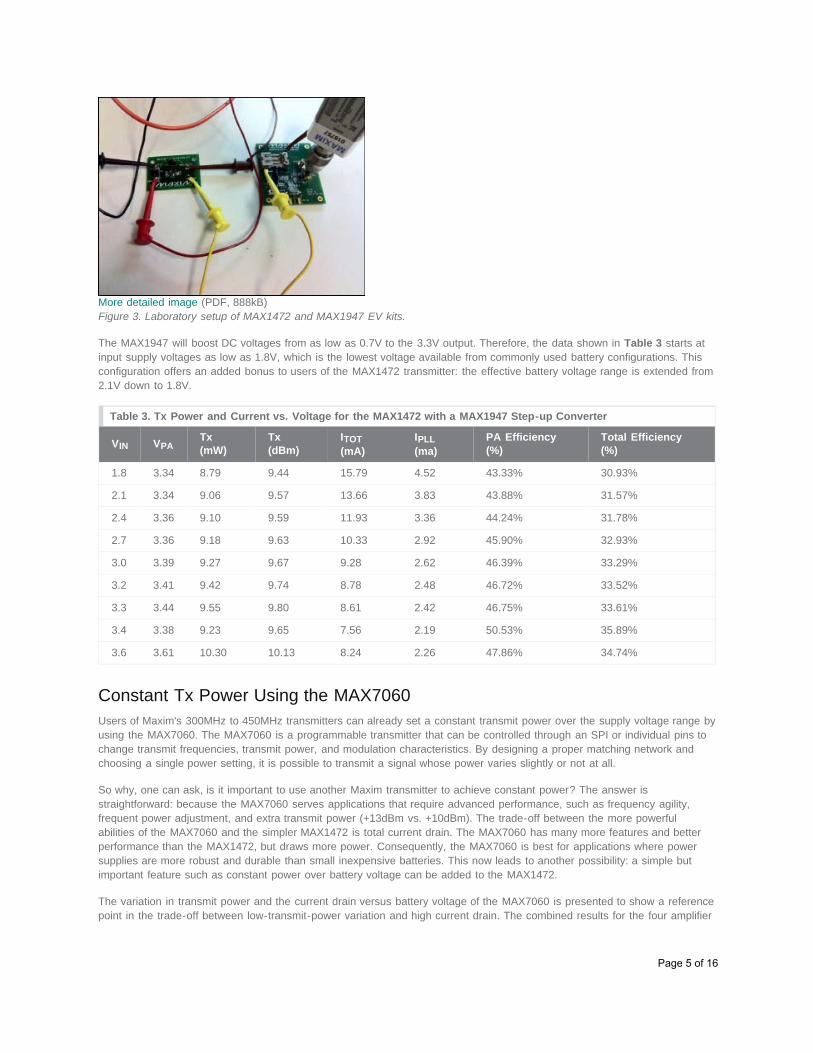
More detailed image (PDF, 888kB)Figure 3. Laboratory setup of MAX1472 and MAX1947 EV kits.
The MAX1947 will boost DC voltages from as low as 0.7V to the 3.3V output. Therefore, the data shown in Table 3 starts atinput supply voltages as low as 1.8V, which is the lowest voltage available from commonly used battery configurations. Thisconfiguration offers an added bonus to users of the MAX1472 transmitter: the effective battery voltage range is extended from2.1V down to 1.8V.
Table 3. Tx Power and Current vs. Voltage for the MAX1472 with a MAX1947 Step-up Converter
VIN VPATx(mW)
Tx(dBm)
ITOT(mA)
IPLL(ma)
PA Efficiency(%)
Total Efficiency(%)
1.8 3.34 8.79 9.44 15.79 4.52 43.33% 30.93%
2.1 3.34 9.06 9.57 13.66 3.83 43.88% 31.57%
2.4 3.36 9.10 9.59 11.93 3.36 44.24% 31.78%
2.7 3.36 9.18 9.63 10.33 2.92 45.90% 32.93%
3.0 3.39 9.27 9.67 9.28 2.62 46.39% 33.29%
3.2 3.41 9.42 9.74 8.78 2.48 46.72% 33.52%
3.3 3.44 9.55 9.80 8.61 2.42 46.75% 33.61%
3.4 3.38 9.23 9.65 7.56 2.19 50.53% 35.89%
3.6 3.61 10.30 10.13 8.24 2.26 47.86% 34.74%
Constant Tx Power Using the MAX7060Users of Maxim's 300MHz to 450MHz transmitters can already set a constant transmit power over the supply voltage range byusing the MAX7060. The MAX7060 is a programmable transmitter that can be controlled through an SPI or individual pins tochange transmit frequencies, transmit power, and modulation characteristics. By designing a proper matching network andchoosing a single power setting, it is possible to transmit a signal whose power varies slightly or not at all.
So why, one can ask, is it important to use another Maxim transmitter to achieve constant power? The answer isstraightforward: because the MAX7060 serves applications that require advanced performance, such as frequency agility,frequent power adjustment, and extra transmit power (+13dBm vs. +10dBm). The trade-off between the more powerfulabilities of the MAX7060 and the simpler MAX1472 is total current drain. The MAX7060 has many more features and betterperformance than the MAX1472, but draws more power. Consequently, the MAX7060 is best for applications where powersupplies are more robust and durable than small inexpensive batteries. This now leads to another possibility: a simple butimportant feature such as constant power over battery voltage can be added to the MAX1472.
The variation in transmit power and the current drain versus battery voltage of the MAX7060 is presented to show a referencepoint in the trade-off between low-transmit-power variation and high current drain. The combined results for the four amplifier
configurations (the MAX1472 with a 2.7V match, the MAX1472 with a 3.3V match, the MAX1472 and MAX1947, and theMAX7060) illustrate the difference in performance.
Table 4 has the same format as Tables 1, 2, and 3. It shows the transmit power and the current drain as a function of thebattery voltage for the MAX7060. The Tx power setting on the MAX7060 was fixed at 2dB below the maximum power setting.This setting keeps the power nearly constant (< 1dB decrease) as battery voltages increase from 2.4 to 3.6V, losing another1dB when the voltage drops to 2.1V.
Table 4. Tx Power and Current vs. Voltage of the MAX7060 with a 2.7V Match
VIN VPATx(mW)
Tx(dBm)
ITOT(mA)
IPLL(ma)
PA Efficiency(%)
Total Efficiency(%)
2.1 0x1C 6.46 8.10 12.06 4.38 40.03% 25.49%
2.4 0x1C 8.65 9.37 13.63 4.62 40.00% 26.44%
2.7 0x1C 9.57 9.81 14.42 4.90 37.24% 24.59%
3.0 0x1C 9.77 9.90 15.01 5.13 32.97% 21.70%
3.3 0x1C 9.77 9.90 15.50 5.42 29.38% 19.11%
3.6 0x1C 10.00 10.00 16.10 5.66 26.61% 17.25%
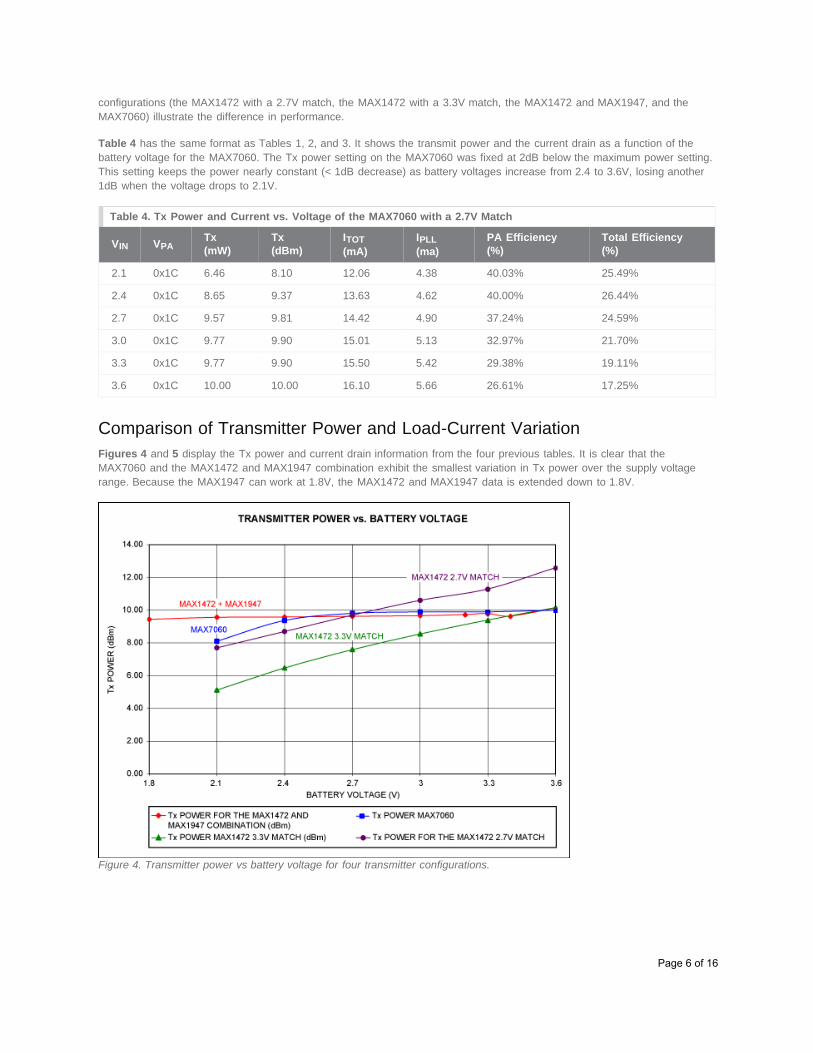
Comparison of Transmitter Power and Load-Current VariationFigures 4 and 5 display the Tx power and current drain information from the four previous tables. It is clear that theMAX7060 and the MAX1472 and MAX1947 combination exhibit the smallest variation in Tx power over the supply voltagerange. Because the MAX1947 can work at 1.8V, the MAX1472 and MAX1947 data is extended down to 1.8V.
Figure 4. Transmitter power vs battery voltage for four transmitter configurations.
Page 6 of 16
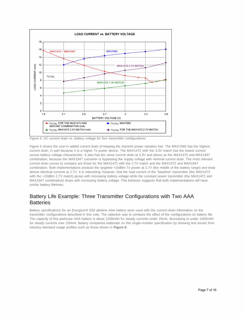
Figure 5. DC current drain vs. battery voltage for four transmitter configurations.
Figure 5 shows the cost in added current drain of keeping the transmit power variation low. The MAX7060 has the highestcurrent drain, in part because it is a higher Tx power device. The MAX1472 with the 3.3V match has the lowest currentversus battery-voltage characteristic. It also has the same current drain at 3.3V and above as the MAX1472 and MAX1947combination, because the MAX1947 converter is bypassing the supply voltage with minimal current drain. The most relevantcurrent-drain curves to compare are those for the MAX1472 with the 2.7V match and the MAX1472 and MAX1947combination. Both implementations produce the targeted +10dBm Tx power at 2.7V (the middle of the battery range) and drawalmost identical currents at 2.7V. It is interesting, however, that the load current of the "baseline" transmitter (the MAX1472with the +10dBm 2.7V match) grows with increasing battery voltage while the constant power transmitter (the MAX1472 andMAX1947 combination) drops with increasing battery voltage. This behavior suggests that both implementations will havesimilar battery lifetimes.
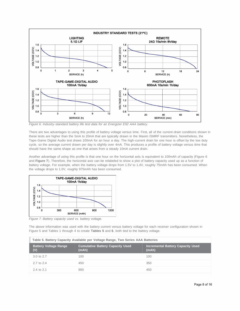
Battery Life Example: Three Transmitter Configurations with Two AAABatteriesBattery specifications for an Energizer® E92 alkaline AAA battery were used with the current-drain information on thetransmitter configurations described in this note. The objective was to compare the effect of the configurations on battery life.The capacity of this particular AAA battery is about 1200mAh for steady currents under 25mA, decreasing to under 1000mAhfor steady currents over 100mA. Battery companies elaborate on this single-number specification by showing test results fromindustry-standard usage profiles such as those shown in Figure 6.
Page 7 of 16
Figure 6. Industry-standard battery life test data for an Energizer E92 AAA battery.
There are two advantages to using this profile of battery voltage versus time. First, all of the current-drain conditions shown inthese tests are higher than the 5mA to 20mA that are typically drawn in the Maxim ISMRF transmitters. Nonetheless, theTape-Game Digital Audio test draws 100mA for an hour a day. The high-current drain for one hour is offset by the low dutycycle, so the average current drawn per day is slightly over 4mA. This produces a profile of battery voltage versus time thatshould have the same shape as one that arises from a steady 10mA current drain.
Another advantage of using this profile is that one hour on the horizontal axis is equivalent to 100mAh of capacity (Figure 6and Figure 7). Therefore, the horizontal axis can be relabeled to show a plot of battery capacity used up as a function ofbattery voltage. For example, when the battery voltage drops from 1.5V to 1.4V, roughly 75mAh has been consumed. Whenthe voltage drops to 1.0V, roughly 975mAh has been consumed.
Figure 7. Battery capacity used vs. battery voltage.
The above information was used with the battery current versus battery voltage for each receiver configuration shown inFigure 5 and Tables 1 through 4 to create Tables 5 and 6, both tied to the battery voltage.
Table 5. Battery Capacity Available per Voltage Range, Two Series AAA Batteries
Battery Voltage Range(V)
Cumulative Battery Capacity Used(mAh)
Incremental Battery Capacity Used(mAh)
3.0 to 2.7 100 100
2.7 to 2.4 450 350
2.4 to 2.1 900 450
Page 8 of 16
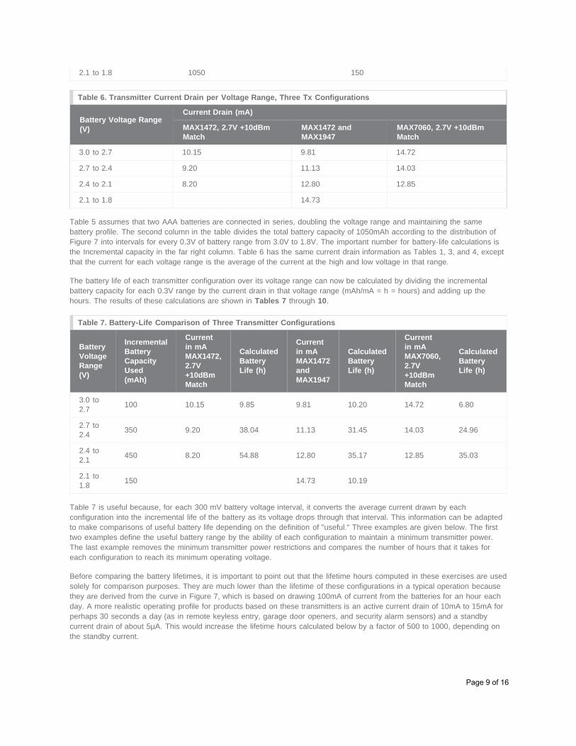
2.1 to 1.8 1050 150
Table 6. Transmitter Current Drain per Voltage Range, Three Tx Configurations
Battery Voltage Range(V)
Current Drain (mA)
MAX1472, 2.7V +10dBmMatch
MAX1472 andMAX1947
MAX7060, 2.7V +10dBmMatch
3.0 to 2.7 10.15 9.81 14.72
2.7 to 2.4 9.20 11.13 14.03
2.4 to 2.1 8.20 12.80 12.85
2.1 to 1.8 14.73
Table 5 assumes that two AAA batteries are connected in series, doubling the voltage range and maintaining the samebattery profile. The second column in the table divides the total battery capacity of 1050mAh according to the distribution ofFigure 7 into intervals for every 0.3V of battery range from 3.0V to 1.8V. The important number for battery-life calculations isthe Incremental capacity in the far right column. Table 6 has the same current drain information as Tables 1, 3, and 4, exceptthat the current for each voltage range is the average of the current at the high and low voltage in that range.
The battery life of each transmitter configuration over its voltage range can now be calculated by dividing the incrementalbattery capacity for each 0.3V range by the current drain in that voltage range (mAh/mA = h = hours) and adding up thehours. The results of these calculations are shown in Tables 7 through 10.
Table 7. Battery-Life Comparison of Three Transmitter Configurations
BatteryVoltageRange(V)
IncrementalBatteryCapacityUsed(mAh)
Currentin mAMAX1472,2.7V+10dBmMatch
CalculatedBatteryLife (h)
Currentin mAMAX1472andMAX1947
CalculatedBatteryLife (h)
Currentin mAMAX7060,2.7V+10dBmMatch
CalculatedBatteryLife (h)
3.0 to2.7 100 10.15 9.85 9.81 10.20 14.72 6.80
2.7 to2.4 350 9.20 38.04 11.13 31.45 14.03 24.96
2.4 to2.1 450 8.20 54.88 12.80 35.17 12.85 35.03
2.1 to1.8 150 14.73 10.19
Table 7 is useful because, for each 300 mV battery voltage interval, it converts the average current drawn by eachconfiguration into the incremental life of the battery as its voltage drops through that interval. This information can be adaptedto make comparisons of useful battery life depending on the definition of "useful." Three examples are given below. The firsttwo examples define the useful battery range by the ability of each configuration to maintain a minimum transmitter power.The last example removes the minimum transmitter power restrictions and compares the number of hours that it takes foreach configuration to reach its minimum operating voltage.
Before comparing the battery lifetimes, it is important to point out that the lifetime hours computed in these exercises are usedsolely for comparison purposes. They are much lower than the lifetime of these configurations in a typical operation becausethey are derived from the curve in Figure 7, which is based on drawing 100mA of current from the batteries for an hour eachday. A more realistic operating profile for products based on these transmitters is an active current drain of 10mA to 15mA forperhaps 30 seconds a day (as in remote keyless entry, garage door openers, and security alarm sensors) and a standbycurrent drain of about 5µA. This would increase the lifetime hours calculated below by a factor of 500 to 1000, depending onthe standby current.
Page 9 of 16
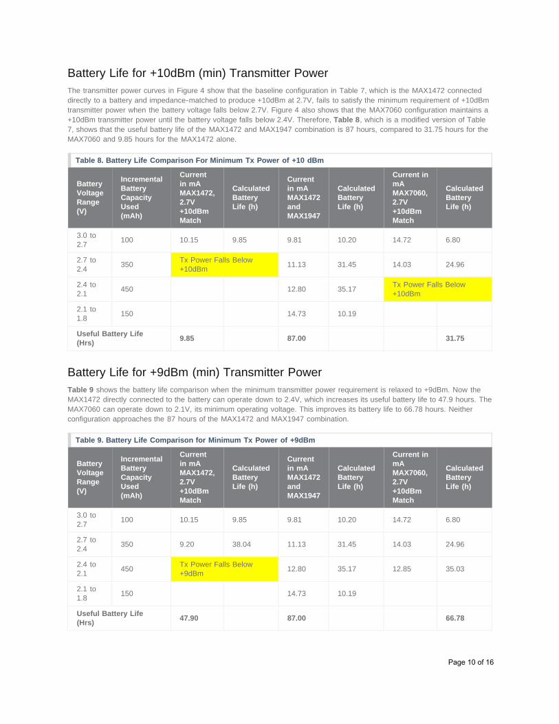
Battery Life for +10dBm (min) Transmitter PowerThe transmitter power curves in Figure 4 show that the baseline configuration in Table 7, which is the MAX1472 connecteddirectly to a battery and impedance-matched to produce +10dBm at 2.7V, fails to satisfy the minimum requirement of +10dBmtransmitter power when the battery voltage falls below 2.7V. Figure 4 also shows that the MAX7060 configuration maintains a+10dBm transmitter power until the battery voltage falls below 2.4V. Therefore, Table 8, which is a modified version of Table7, shows that the useful battery life of the MAX1472 and MAX1947 combination is 87 hours, compared to 31.75 hours for theMAX7060 and 9.85 hours for the MAX1472 alone.
Table 8. Battery Life Comparison For Minimum Tx Power of +10 dBm
BatteryVoltageRange(V)
IncrementalBatteryCapacityUsed(mAh)
Currentin mAMAX1472,2.7V+10dBmMatch
CalculatedBatteryLife (h)
Currentin mAMAX1472andMAX1947
CalculatedBatteryLife (h)
Current inmAMAX7060,2.7V+10dBmMatch
CalculatedBatteryLife (h)
3.0 to2.7 100 10.15 9.85 9.81 10.20 14.72 6.80
2.7 to2.4 350 Tx Power Falls Below
+10dBm 11.13 31.45 14.03 24.96
2.4 to2.1 450 12.80 35.17 Tx Power Falls Below
+10dBm
2.1 to1.8 150 14.73 10.19
Useful Battery Life(Hrs) 9.85 87.00 31.75
Battery Life for +9dBm (min) Transmitter PowerTable 9 shows the battery life comparison when the minimum transmitter power requirement is relaxed to +9dBm. Now theMAX1472 directly connected to the battery can operate down to 2.4V, which increases its useful battery life to 47.9 hours. TheMAX7060 can operate down to 2.1V, its minimum operating voltage. This improves its battery life to 66.78 hours. Neitherconfiguration approaches the 87 hours of the MAX1472 and MAX1947 combination.
Table 9. Battery Life Comparison for Minimum Tx Power of +9dBm
BatteryVoltageRange(V)
IncrementalBatteryCapacityUsed(mAh)
Currentin mAMAX1472,2.7V+10dBmMatch
CalculatedBatteryLife (h)
Currentin mAMAX1472andMAX1947
CalculatedBatteryLife (h)
Current inmAMAX7060,2.7V+10dBmMatch
CalculatedBatteryLife (h)
3.0 to2.7 100 10.15 9.85 9.81 10.20 14.72 6.80
2.7 to2.4 350 9.20 38.04 11.13 31.45 14.03 24.96
2.4 to2.1 450 Tx Power Falls Below
+9dBm 12.80 35.17 12.85 35.03
2.1 to1.8 150 14.73 10.19
Useful Battery Life(Hrs) 47.90 87.00 66.78
Page 10 of 16
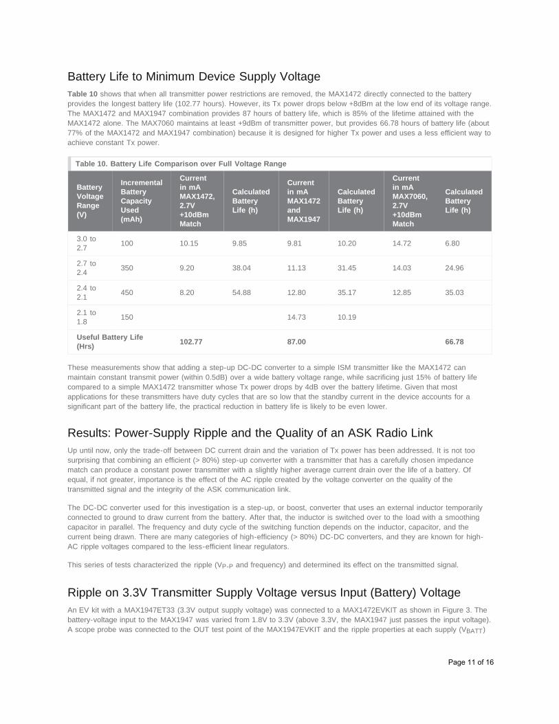
Battery Life to Minimum Device Supply VoltageTable 10 shows that when all transmitter power restrictions are removed, the MAX1472 directly connected to the batteryprovides the longest battery life (102.77 hours). However, its Tx power drops below +8dBm at the low end of its voltage range.The MAX1472 and MAX1947 combination provides 87 hours of battery life, which is 85% of the lifetime attained with theMAX1472 alone. The MAX7060 maintains at least +9dBm of transmitter power, but provides 66.78 hours of battery life (about77% of the MAX1472 and MAX1947 combination) because it is designed for higher Tx power and uses a less efficient way toachieve constant Tx power.
Table 10. Battery Life Comparison over Full Voltage Range
BatteryVoltageRange(V)
IncrementalBatteryCapacityUsed(mAh)
Currentin mAMAX1472,2.7V+10dBmMatch
CalculatedBatteryLife (h)
Currentin mAMAX1472andMAX1947
CalculatedBatteryLife (h)
Currentin mAMAX7060,2.7V+10dBmMatch
CalculatedBatteryLife (h)
3.0 to2.7 100 10.15 9.85 9.81 10.20 14.72 6.80
2.7 to2.4 350 9.20 38.04 11.13 31.45 14.03 24.96
2.4 to2.1 450 8.20 54.88 12.80 35.17 12.85 35.03
2.1 to1.8 150 14.73 10.19
Useful Battery Life(Hrs) 102.77 87.00 66.78
These measurements show that adding a step-up DC-DC converter to a simple ISM transmitter like the MAX1472 canmaintain constant transmit power (within 0.5dB) over a wide battery voltage range, while sacrificing just 15% of battery lifecompared to a simple MAX1472 transmitter whose Tx power drops by 4dB over the battery lifetime. Given that mostapplications for these transmitters have duty cycles that are so low that the standby current in the device accounts for asignificant part of the battery life, the practical reduction in battery life is likely to be even lower.
Results: Power-Supply Ripple and the Quality of an ASK Radio LinkUp until now, only the trade-off between DC current drain and the variation of Tx power has been addressed. It is not toosurprising that combining an efficient (> 80%) step-up converter with a transmitter that has a carefully chosen impedancematch can produce a constant power transmitter with a slightly higher average current drain over the life of a battery. Ofequal, if not greater, importance is the effect of the AC ripple created by the voltage converter on the quality of thetransmitted signal and the integrity of the ASK communication link.
The DC-DC converter used for this investigation is a step-up, or boost, converter that uses an external inductor temporarilyconnected to ground to draw current from the battery. After that, the inductor is switched over to the load with a smoothingcapacitor in parallel. The frequency and duty cycle of the switching function depends on the inductor, capacitor, and thecurrent being drawn. There are many categories of high-efficiency (> 80%) DC-DC converters, and they are known for high-AC ripple voltages compared to the less-efficient linear regulators.
This series of tests characterized the ripple (VP-P and frequency) and determined its effect on the transmitted signal.
Ripple on 3.3V Transmitter Supply Voltage versus Input (Battery) VoltageAn EV kit with a MAX1947ET33 (3.3V output supply voltage) was connected to a MAX1472EVKIT as shown in Figure 3. Thebattery-voltage input to the MAX1947 was varied from 1.8V to 3.3V (above 3.3V, the MAX1947 just passes the input voltage).A scope probe was connected to the OUT test point of the MAX1947EVKIT and the ripple properties at each supply (VBATT)
Page 11 of 16
setting were recorded. Table 11 shows the peak-to-peak amplitude and the period of the ripple. The ripple waveform is asawtooth, which is characteristic of an hysteretical converter that uses a threshold-feedback process instead of a duty-cycle-controlled converter.
Table 11. AC Ripple Characteristics of the MAX1947 Output Voltage Loaded with a MAX1472 Transmitter BatteryVoltage Peak-to-Peak Ripple Amplitude (mV) Ripple Period (µs)
Battery Voltage Peak-to-Peak Ripple Amplitude (mV) Ripple Period (µs)
1.8 75 45
2.1 100 70
2.4 100 80
2.7 100 120
3.0 160 180
3.3 220 330
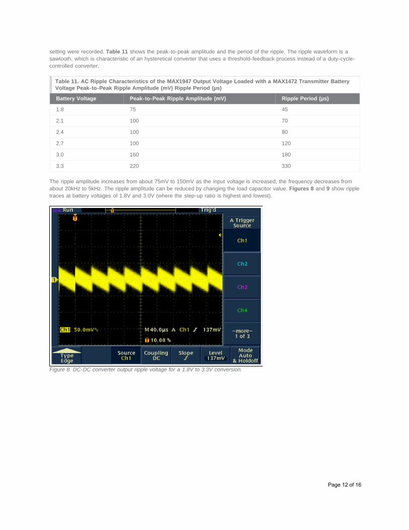
The ripple amplitude increases from about 75mV to 150mV as the input voltage is increased; the frequency decreases fromabout 20kHz to 5kHz. The ripple amplitude can be reduced by changing the load capacitor value. Figures 8 and 9 show rippletraces at battery voltages of 1.8V and 3.0V (where the step-up ratio is highest and lowest).
Figure 8. DC-DC converter output ripple voltage for a 1.8V to 3.3V conversion.
Page 12 of 16
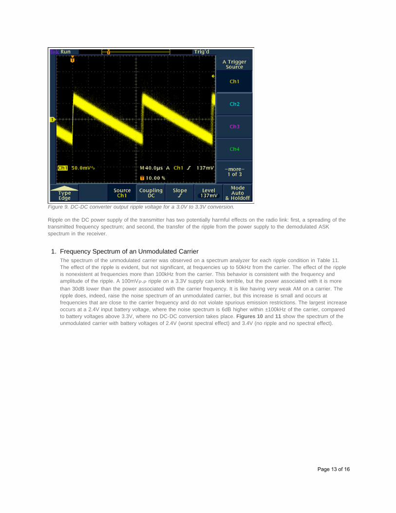
Figure 9. DC-DC converter output ripple voltage for a 3.0V to 3.3V conversion.
Ripple on the DC power supply of the transmitter has two potentially harmful effects on the radio link: first, a spreading of thetransmitted frequency spectrum; and second, the transfer of the ripple from the power supply to the demodulated ASKspectrum in the receiver.
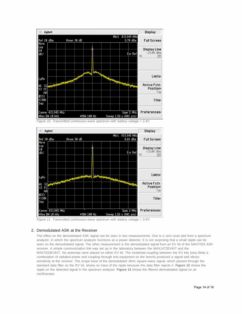
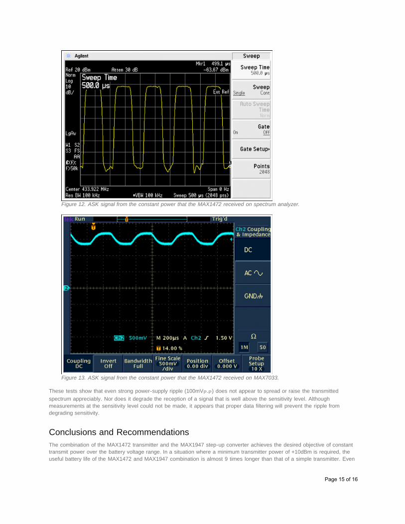
1. Frequency Spectrum of an Unmodulated CarrierThe spectrum of the unmodulated carrier was observed on a spectrum analyzer for each ripple condition in Table 11.The effect of the ripple is evident, but not significant, at frequencies up to 50kHz from the carrier. The effect of the rippleis nonexistent at frequencies more than 100kHz from the carrier. This behavior is consistent with the frequency andamplitude of the ripple. A 100mVP-P ripple on a 3.3V supply can look terrible, but the power associated with it is morethan 30dB lower than the power associated with the carrier frequency. It is like having very weak AM on a carrier. Theripple does, indeed, raise the noise spectrum of an unmodulated carrier, but this increase is small and occurs atfrequencies that are close to the carrier frequency and do not violate spurious emission restrictions. The largest increaseoccurs at a 2.4V input battery voltage, where the noise spectrum is 6dB higher within ±100kHz of the carrier, comparedto battery voltages above 3.3V, where no DC-DC conversion takes place. Figures 10 and 11 show the spectrum of theunmodulated carrier with battery voltages of 2.4V (worst spectral effect) and 3.4V (no ripple and no spectral effect).
Page 13 of 16
Figure 10. Transmitted continuous-wave spectrum with battery voltage = 2.4V.
Figure 11. Transmitted continuous-wave spectrum with battery voltage = 3.4V.
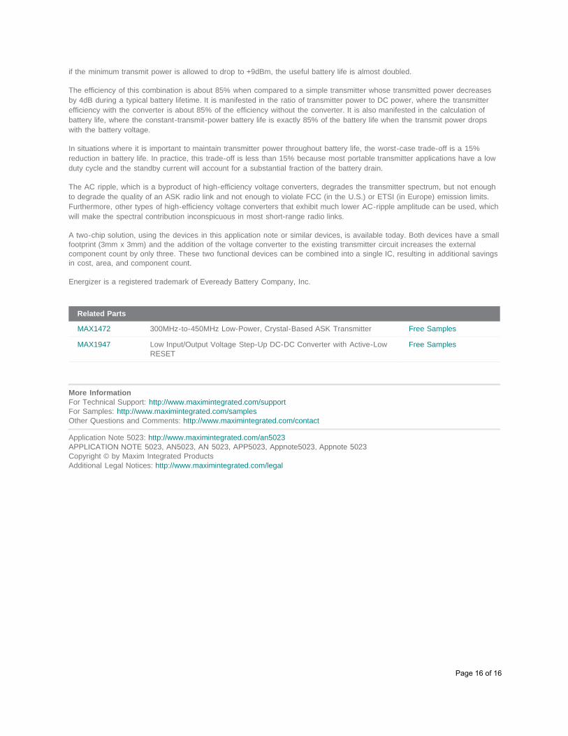
2. Demodulated ASK at the ReceiverThe effect on the demodulated ASK signal can be seen in two measurements. One is a zero-scan plot from a spectrumanalyzer, in which the spectrum analyzer functions as a power detector. It is not surprising that a small ripple can beseen on the demodulated signal. The other measurement is the demodulated signal from an EV kit of the MAX7033 ASKreceiver. A simple communication link was set up in the laboratory between the MAX1472EVKIT and theMAX7033EVKIT. No antennas were placed on either EV kit. The incidental coupling between the EV kits (very likely acombination of radiated power and coupling through test equipment on the bench) produced a signal well abovesensitivity at the receiver. The scope trace of the demodulated 2kHz square-wave signal, which passed through thestandard data filter on the EV kit, shows no trace of the ripple because the data filter rejects it. Figure 12 shows theripple on the detected signal in the spectrum analyzer. Figure 13 shows the filtered demodulated signal on anoscilloscope.
Page 14 of 16
Figure 12. ASK signal from the constant power that the MAX1472 received on spectrum analyzer.
Figure 13. ASK signal from the constant power that the MAX1472 received on MAX7033.
These tests show that even strong power-supply ripple (100mVP-P) does not appear to spread or raise the transmittedspectrum appreciably. Nor does it degrade the reception of a signal that is well above the sensitivity level. Althoughmeasurements at the sensitivity level could not be made, it appears that proper data filtering will prevent the ripple fromdegrading sensitivity.
Conclusions and RecommendationsThe combination of the MAX1472 transmitter and the MAX1947 step-up converter achieves the desired objective of constanttransmit power over the battery voltage range. In a situation where a minimum transmitter power of +10dBm is required, theuseful battery life of the MAX1472 and MAX1947 combination is almost 9 times longer than that of a simple transmitter. Even
Page 15 of 16
if the minimum transmit power is allowed to drop to +9dBm, the useful battery life is almost doubled.
The efficiency of this combination is about 85% when compared to a simple transmitter whose transmitted power decreasesby 4dB during a typical battery lifetime. It is manifested in the ratio of transmitter power to DC power, where the transmitterefficiency with the converter is about 85% of the efficiency without the converter. It is also manifested in the calculation ofbattery life, where the constant-transmit-power battery life is exactly 85% of the battery life when the transmit power dropswith the battery voltage.
In situations where it is important to maintain transmitter power throughout battery life, the worst-case trade-off is a 15%reduction in battery life. In practice, this trade-off is less than 15% because most portable transmitter applications have a lowduty cycle and the standby current will account for a substantial fraction of the battery drain.
The AC ripple, which is a byproduct of high-efficiency voltage converters, degrades the transmitter spectrum, but not enoughto degrade the quality of an ASK radio link and not enough to violate FCC (in the U.S.) or ETSI (in Europe) emission limits.Furthermore, other types of high-efficiency voltage converters that exhibit much lower AC-ripple amplitude can be used, whichwill make the spectral contribution inconspicuous in most short-range radio links.
A two-chip solution, using the devices in this application note or similar devices, is available today. Both devices have a smallfootprint (3mm x 3mm) and the addition of the voltage converter to the existing transmitter circuit increases the externalcomponent count by only three. These two functional devices can be combined into a single IC, resulting in additional savingsin cost, area, and component count.
Energizer is a registered trademark of Eveready Battery Company, Inc.