7
ISO 15552 PNEUMATIC CYLINDERS ISP-M SERIES Ø32 - Ø125

ISO 15552 PNEUMATIC CYLINDERS
ISP-M SERIES Ø32 - Ø125
www.pemaks.com.tr
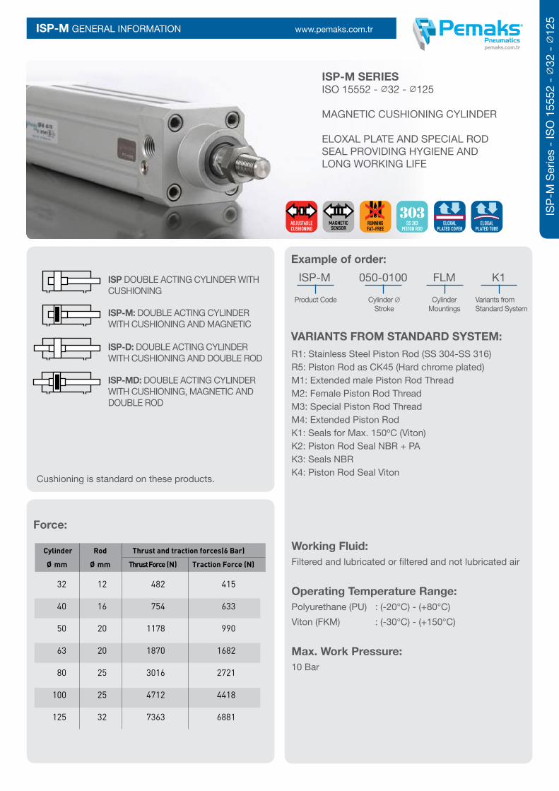
ISP-M SERIES ISO 15552 - ∅32 - ∅125
MAGNETIC CUSHIONING CYLINDER
ELOXAL PLATE AND SPECIAL ROD SEAL PROVIDING HYGIENE AND LONG WORKING LIFE
ISP-M GENERAL INFORMATION
ISP DOUBLE ACTING CYLINDER WITH CUSHIONING
ISP-M: DOUBLE ACTING CYLINDER WITH CUSHIONING AND MAGNETIC
ISP-D: DOUBLE ACTING CYLINDER WITH CUSHIONING AND DOUBLE ROD
ISP-MD: DOUBLE ACTING CYLINDER WITH CUSHIONING, MAGNETIC AND DOUBLE ROD
Working Fluid: Filtered and lubricated or filtered and not lubricated air
Operating Temperature Range: Polyurethane (PU) : (-20°C) - (+80°C)Viton (FKM) : (-30°C) - (+150°C)
Max. Work Pressure: 10 Bar
Example of order:
VARIANTS FROM STANDARD SYSTEM:R1: Stainless Steel Piston Rod (SS 304-SS 316) R5: Piston Rod as CK45 (Hard chrome plated) M1: Extended male Piston Rod Thread M2: Female Piston Rod Thread M3: Special Piston Rod Thread M4: Extended Piston Rod K1: Seals for Max. 150ºC (Viton) K2: Piston Rod Seal NBR + PA K3: Seals NBR K4: Piston Rod Seal Viton
ISP-M 050-0100 FLM K1
Product Code Cylinder ∅ Cylinder Variants from Stroke Mountings Standard System
Force:
Cylinder Rod Thrust and traction forces(6 Bar) Ø mm Ø mm Thrust Force (N) Traction Force (N) 32 12 482 415 40 16 754 633 50 20 1178 990 63 20 1870 1682 80 25 3016 2721 100 25 4712 4418 125 32 7363 6881
Cushioning is standard on these products.
ISP-
M S
erie
s - I
SO 1
5552
- ∅
32 - ∅
125
RUNNINGFAT-FREE
ADJUSTABLECUSHIONING
ELOXALPLATED TUBE
ELOXALPLATED COVER
SS 303PISTON ROD

www.pemaks.com.trISP-M TECHNICAL DATA
No MATERIAL NAME CHARACTERISTIC PC. No MATERIAL NAME CHARACTERISTIC PC.
12 Piston Seal PU 2
13 Middle Piston O-ring NBR 1
14 Rod Seal HYTREL + PU 1
15 Guiding Band Polyacetal 1
16 Guiding Bush CSB-40 1
17 Magnet 1
18 Nut Stainless Steel 1
Note:Dia 32: Instead of Cushioning Plastic is used Cushioning yellow and instead of Cushioning Plastic Female Thread is used Cushioning yellow Female Thread.(Material:Brass)
Dia 125:Instead of Cushioning Plastic is used Cushioning Aluminium and instead of Cushioning Plastic Female Thread is used Cushioning Aluminium Female Thread. (Material: Anodized Aluminium)
1 Rear Head 6082 Al.+ Eloxal Plated 1
2 Front Head 6082 Al.+ Eloxal Plated 1
3 Middle Piston Aluminium 2
4 Piston Rod X20 Cr13 Hard Chrome Plated 1
5 Tube Al Mg Si 0,5 + Eloxal Plated 1
6 Bolt Stainless Steel 8
7 Cushioning Screw Brass+AISI 303 NBR 2
8 Cushioning Plastic Polyacetal 2
9 Cushioning Fem. Thread Galvanized Steel 1
10 Cushioning Seal PU 2
11 Head O-ring NBR 2

www.pemaks.com.tr
Cylinder A B B1 D D1 D3 D4 D5 D6 D7 L0 L1 L2 L3 L4 L10 L11 SW * Ø mm Ø Ø Ø
32 30 22 32,5 12 M10x1.25 30 59 45 46 M6 116 94 18 4 25 120 146 10 G1/8’’
40 34 24 38 16 M12x1.25 35 70,2 54 53,7 M6 129 105 20 4 27 135 165 13 G1/4’’
50 41 32 46,5 20 M16x1.5 40 84,2 65 65,7 M8 138 106 28 4 29,5 143 180 17 G1/4’’
63 42 32 56,5 20 M16x1.5 45 99,5 76 80 M8 152 121 27 4 34,5 158 195 17 G3/8’’
80 52 40 72 25 M20x1.5 45 123,8 94 101,8 M10 167 128 34 4 35 174 220 22 G3/8’’
100 52,5 40 89 25 M20x1.5 55 148,8 112 125,9 M10 182,5 138 38,5 4 38 189 240 22 G1/2’’
125 73 54 110 32 M27x2 60 179,5 134 155,5 M12 213 160 46 6 44 225 290 27 G1/2’’
ISP-M CYLINDER DIMENSIONS
ISP-
M S
erie
s - I
SO 1
5552
- ∅
32 - ∅
125
L10+Stroke
L11+(2xStroke)
L0+Stroke
L1+Stroke
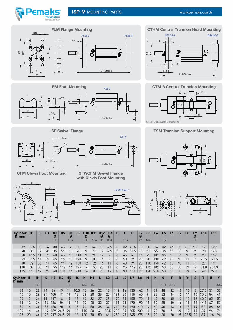
www.pemaks.com.trISP-M MOUNTING PARTS
Cylinder B1 C C1 D3 D5 D8 D9 D10 D11 D12 D14 E F F1 F2 F3 F4 F5 F6 F7 F8 F9 F10 F11 Ø mm Ø Ø Ø Ø Ø Ø Ø H11 H14 H13 JS14 H9 H13 JS14 e9 h14 ±0,2 H13
32 32.5 30 24 30 45 7 80 7 64 10 6.6 5 32 45.5 12 50 74 32 46 30 6.8 6.6 17 129 40 38 37 28 35 54 10 90 9 72 12 6.6 5 36 54.5 16 63 95 36 55 36 9 9 20 145 50 46.5 41 32 40 65 10 110 9 90 12 9 6 45 65 16 75 107 36 55 36 9 9 23 157 63 56.5 44 32 45 76 10 120 9 100 16 9 6 50 76 20 90 130 42 65 40 11 11 23.5 171.5 80 72 56 41 45 94 12 150 12 126 16 11 6 63 94 20 110 150 42 65 40 11 11 29 191 100 89 58 41 55 112 14 175 14 150 20 11 6 75 112 25 132 182 50 75 50 13 14 31.8 208.3 125 110 67 45 60 134 16 210 16 180 25 14 8 90 131 25 160 210 50 75 50 13 14 42 248
Cylinder H H1 H2 H3 H4 H5 H6 K K1 L L2 L5 L6 L7 L8 M N O P R R1 S T U VØ mm Ø -0,2 H13 h14 H14 JS14 JS16 JS14 32 10 28 71 86 15 11 10.5 45 26 22 18 142 16 130 142 9 31 18 32 10 10 8 27.5 51 38 40 10 28 87 105 18 15 12 52 28 25 20 161 20 145 160 9 35 22 36 12 11 10 30.5 54 41 50 12 34 99 117 18 15 12 60 32 27 28 170 25 155 170 11 45 30 45 13 13 12 40.5 65 50 63 12 34 116 136 20 18 13 70 40 32 27 185 25 170 190 11 50 35 50 16 15 12 44.5 67 52 80 16 34 136 156 20 18 13 90 50 36 34 210 30 190 210 14 60 40 63 16 15 14 57 86 66 100 16 44 164 189 24.5 20 16 110 60 41 38.5 220 35 205 230 14 70 50 71 20 19 15 65 96 76 125 20 44 192 217 24.5 20 16 130 70 50 46 250 45 245 275 15 90 60 90 25 22.5 20 85 124 94
CTHM-1 CTHM-3
FLM Flange Mounting CTHM Central Trunnion Head Mounting
CTM-3 Central Trunnion Mounting
CTM3 :Adjustable Connection
TSM Trunnion Support Mounting
CFM Clevis Foot Mounting SFWCFM Swivel Flangewith Clevis Foot Mounting
SF Swivel Flange
FM Foot Mounting
FLM-1
FM-1
SF-1
SFWCFM-1
FLM-3
L7+Stroke
L5+Stroke
L8+Stroke
F11+Stroke

www.pemaks.com.tr
ISP-
M S
erie
s - I
SO 1
5552
- ∅
32 - ∅
125
ISP-M MOUNTING PARTS ASSEMBLY OF FIGURES
FLM Flange Mounting
SFWCFM Swivel Flange with Clevis Foot Mounting
CTM Central Trunnion Mounting
CTHM Central TrunnionHead Mounting
SF Swivel Flange
FM Foot Mounting
FLM-1
FLM-2
FM-1 FM-2
FM-3
FLM-3
FLM-4
SFWCFM-1
SFWCFM-3
SFWCFM-2
SF-1 SF-2
CTHM-1
CTM-3CTM-4
CTHM-3
CTHM-2 CTHM-4

www.pemaks.com.trISP-M ROD ENDS
Dimensions (mm)
Part No. d d3 B C1 W L3 d2 L4 h1 L5 d4 d5 dk a° 6H min KMB 10 -1 10 M10x1.25 14 10.5 17 20 26 56 43 6.5 15 19 19.05 13 KMB 12 -1 12 M12x1.25 16 12 19 22 30 65 50 6.5 17.5 22 22.225 13 KMB 16 -1 16 M16x1.5 21 15 22 28 40 84 64 8 22 27 28.575 15 KMB 20 20 M20x1.5 25 18 30 33 50 102 77 10 27.5 34 34.925 14 KMB 28 28 M27x2.0 35 24 41 48 66 136 103 14 37 46 47.6 15 KMB 30-1 30 M27x2.0 37 25 41 51 70 145 110 15 40 50 50.8 17 KMB 30 30 M30x2.0 37 25 41 51 70 145 110 15 40 50 50.8 17
Cylinder d1 g a1 a2 b1 b2 d2 d3 f i1 i2 i3 r Ø mm H9 ±0,5 h 11 +0,3 B 13 6H ±0,3 ±0,2 ±0,5 ±0,2 -0,16
32 10 20 20 20 10 10 M10x1.25 18 0.5 52 40 15 0.5 40 12 24 24 24 12 12 M12x1.25 20 0.5 62 48 18 0.5 50 16 32 32 32 16 16 M16x1.5 26 1 83 64 24 1 63 16 32 32 32 16 16 M16x1.5 26 1 83 64 24 1 80 20 40 40 40 20 20 M20x1.5 34 1.5 105 80 30 1.5 100 20 40 40 40 20 20 M20x1.5 34 1.5 105 80 30 1.5 125 25 50 50 50 25 25 M27x2 42 1.5 132 100 36 1.5


