1 ISO15552 CYLINDERS Installation & Application Data 1 Cylinder should be sized according to work load. 2 Cylinders should be protected from dirty environments. 3 Dirty substances in the pipe must be cleared away before cylinder is connected with pipeline to prevent the entrance of sundries into the cylinder. 4 Use only clean filtered air to 40 µm (lubricated if necessary). 5 Anti-freezing measures shall be adopted under low temperature environments to prevent moisture freezing. 6 Prior to first run, test cylinder under no load. Turn buffer adjustment to minimum and gradually increase to avoid damage. 7 In order for the cylinder to achieve long service life, do not side load cylinder. 8 When the cylinder with magnet is selected and used, it is suggested to use KELM sensor to avoid detecting failure.
Transcript
1
ISO15552 CylInderS
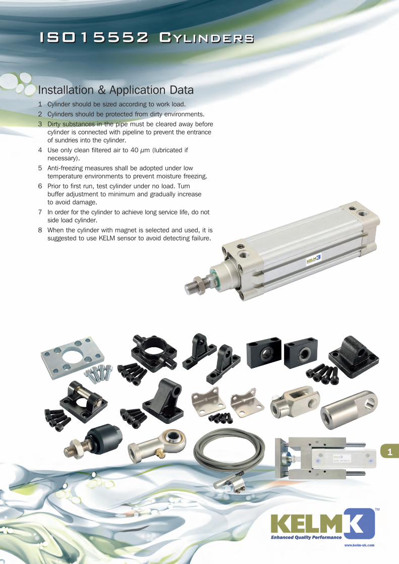
Installation & Application Data1 Cylinder should be sized according to work load.2 Cylinders should be protected from dirty environments.3 Dirty substances in the pipe must be cleared away before
cylinder is connected with pipeline to prevent the entrance of sundries into the cylinder.
4 Use only clean filtered air to 40 µm (lubricated if necessary).
5 Anti-freezing measures shall be adopted under low temperature environments to prevent moisture freezing.
6 Prior to first run, test cylinder under no load. Turn buffer adjustment to minimum and gradually increase to avoid damage.
7 In order for the cylinder to achieve long service life, do not side load cylinder.
8 When the cylinder with magnet is selected and used, it is suggested to use KELM sensor to avoid detecting failure.
5
Gen 1 & 2 ISO15552 CylInderS
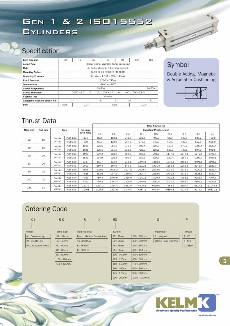
Specification
Thrust Data
Symbol
Ordering CodeK I — 8 0 — B — X — 50 — S — P
Model Bore Size Rod Material Stroke Magnetic Thread
KI : Double Acting
KJ : Double Rod
KK : Adjustable Stroke
32 : 32mm
40 : 40mm
50 : 50mm
63 : 63mm
80 : 80mm
100 : 100mm
125 : 125mm
Blank : Medium Carbon Steel
A : SUS420J2
B : SUS304
C : SUS316
S : Magnetic
Blank : None magnetic
P : PT
T : NPT
G : BSPP
25 : 25mm 250 : 250mm
50 : 50mm 300 : 300mm
75 : 75mm 350 : 350mm
80 : 80mm 450 : 450mm
100 : 100mm 500 : 500mm
125 : 125mm 600 : 600mm
150 : 150mm 700 : 700mm
160 : 160mm 800 : 800mm
175 : 175mm 900 : 900mm
200 : 200mm 1000 : 1000mm
Bore Size mm 32 40 50 63 80 100 125
Acting Type Double Acting, Magnetic, Buffer Cushioning