Isolated Sub-Dehumidification Strategies in Large Supermarkets and Grocery Stores Final Report Submitted to: Refrigeration Project Team Retail Energy Alliance Prepared by: Brian A. Fricke, Ph.D., and Vishal Sharma Oak Ridge National Laboratory Oak Ridge, TN 12 August 2011
Transcript
Isolated Sub-Dehumidification Strategies in Large Supermarkets and Grocery Stores
Final Report
Submitted to:
Refrigeration Project Team Retail Energy Alliance
Prepared by:
Brian A. Fricke, Ph.D., and Vishal Sharma Oak Ridge National Laboratory
Oak Ridge, TN
12 August 2011
i
Contents List of Figures ............................................................................................................................................... iii
List of Tables ................................................................................................................................................ iv
Acknowledgments ......................................................................................................................................... v
1. Goals and Objectives ................................................................................................................................. 1
2. Motivation and Benefits of Reduced Humidity ........................................................................................ 1
Outline of Report ...................................................................................................................................... 3
3. Effects of Humidity on Supermarket Refrigeration Systems .................................................................... 4
5. Whole Store Dehumidification vs. Isolated Sub-Dehumidification ........................................................ 19
Early Studies ............................................................................................................................................ 19
New Construction ................................................................................................................................... 33
Table 4. Estimated Compressor, Defrost Heater and Anti-Sweat Heater Electrical Energy Savings for
Various Refrigerated Display Cases. ........................................................................................................... 27
Table 5. Reduction in Display Case Load due to Reduction in Relative Humidity. .................................... 27
Table 6. Reduction in Compressor Rack Power Requirements due to Reduction in Relative Humidity. .. 28
Table 7. Reduction in Medium Temperature Display Case Electrical Energy Consumption due to
Reduction in Relative Humidity (Westphalen, et al. 1996). ........................................................................ 28
Table 8. Reduction in Low Temperature Display Case Electrical Energy Consumption due to Reduction in
Relative Humidity (Westphalen, et al. 1996). ............................................................................................. 29
Table 9. Refrigeration System Electrical Energy Savings Associated with Reducing Relative Humidity from
55% to 35%. ................................................................................................................................................ 30
v
Acknowledgments The authors would like to thank the U.S. Department of Energy for its support of this project. The
authors would also like to thank the support of the members of the Refrigeration Project Team of the
Retail Energy Alliance.
This document was prepared by the Oak Ridge National Laboratory, Building Equipment Research
Group, Energy & Transportation Science Division.
1
Isolated Sub-Dehumidification Strategies in Large Supermarkets and Grocery Stores
1. Goals and Objectives The objective of this project was to determine the potential energy savings associated with reducing the
relative humidity in the vicinity of refrigerated display cases in supermarkets, as compared to the widely
accepted current practice of maintaining a relatively higher and uniform humidity level throughout the
entire supermarket. Existing and new strategies for maintaining lower relative humidity levels near the
vicinity of refrigerated display cases were analyzed to determine their effectiveness and limits of
application.
2. Motivation and Benefits of Reduced Humidity Retail food stores and supermarkets are energy-intensive commercial buildings, with energy usage
intensities ranging from 43 kW to 70 kW per square foot of floor area (460 kW/m2 to 750 kW/m2) (EIA
2006). Supermarkets operate their refrigeration systems continuously to maintain proper food storage
conditions within their refrigerated display cases and food storage areas. The continual operation of
this equipment accounts for approximately 50% of the total electrical energy consumption of a typical
supermarket (Westphalen, et al. 1996). In addition, approximately 10% of the total electrical energy of a
typical supermarket is consumed by the HVAC system in order to maintain thermal comfort for the
occupants and suitable climatic conditions for the refrigerated display cases (Capozzoli, et al. 2006)
(Kosar and Dumitrescu 2005).
There is a significant interaction between a supermarket’s refrigeration system, its HVAC system and the
ambient conditions within the store. Heat and moisture contained in the conditioned store air are
transferred to the refrigerated display cases, contributing both a latent and sensible heat load to the
supermarket refrigeration system. The moisture which infiltrates into the refrigerated display cases
leads to condensation on the interior surfaces of the display cases and to frost formation on the
evaporator coils. To minimize condensation, anti-sweat heaters are often used to heat door frames and
other interior surfaces of refrigerated display cases. In addition, defrost heaters may be required to
remove frost accumulation on evaporator coils. These heaters add additional sensible heat to the
refrigerated display cases and increase the overall electrical energy consumption of the supermarket.
Dehumidification of the supermarket air with its refrigeration system, rather than its HVAC system, is an
inefficient and energy intensive process. As shown in Figure 1, approximately 1.8 kWh to 2.7 kWh of
energy is required to remove one pound of moisture using the low temperature display cases (Khattar
1992). On the other hand, approximately 0.25 kWh to 0.45 kWh of energy is required to remove one
pound of moisture using the HVAC system (Khattar 1992). Due to the higher suction temperature at the
evaporator in the HVAC system as compared to the refrigeration system, and with the resulting higher
2
coefficient of performance (COP) of the HVAC system as compared to the refrigeration system, it is more
efficient to dehumidify the air using the HVAC system.
Figure 1. Energy required to remove move moisture from air for low-temperature refrigeration, medium temperature refrigeration and HVAC (Khattar 1992).
Reducing the ambient relative humidity within the supermarket by shifting the dehumidification to the
more efficient HVAC system reduces the latent load on the refrigeration system, thereby reducing the
compressor power requirements of the refrigeration system. It has been estimated that for every 0.6°F
(1°C) reduction in dew point temperature, a 2% reduction in refrigeration system energy use can be
achieved (Capozzoli, et al. 2006). In addition, due to less frost formation, fewer and/or shorter defrost
cycles will be required, resulting in lower energy consumption for electric defrost systems. As an added
benefit, fewer defrost cycles reduces the temperature fluctuation of the stored food items within the
display cases, thereby minimizing detrimental impacts on product shelf life and quality. Furthermore,
anti-sweat heater power requirements will be reduced due to less condensation on display case
surfaces.
Other impacts of reduced humidity levels in supermarkets include improved product appearance due to
lack of frost formation on frozen product; the creation of a more comfortable shopping environment;
the reduction in the growth of mold, mildew and fungi; and the increased life of furniture, fixtures and
electronics (Khattar 1992) (Khattar 2004).
The area near the refrigerated display cases requires humidity control in order to obtain efficient
performance from refrigeration system while the dry goods sales area generally requires no humidity
control. Since there are no partitions between the refrigerated display case area and the dry goods area
in the supermarket, moisture will diffuse through the air and migrate to the refrigerated display case
area if the humidity in the dry goods area is higher than in the refrigerated display case area (Khattar
3
2004). Therefore, several researchers have attempted to quantify the impact of reduced humidity level
on the performance of supermarket refrigeration systems as well as to develop new and efficient
strategies to reduce the overall store humidity or the humidity near the refrigerated display cases.
Outline of Report Through this project, an attempt has been made to determine the impact of supermarket relative
humidity on the energy consumption of supermarket refrigeration systems and HVAC systems. The
estimated savings associated with the refrigeration and HVAC systems is then used to determine the
total potential energy savings associated with reducing the relative humidity in the vicinity of
refrigerated display cases in supermarkets.
The following outline summarizes the content of this report.
Section 3, Effects of Humidity on Supermarket Refrigeration Systems
A summary of research is given regarding the effects of humidity level on the performance
of supermarket refrigeration systems.
Section 4, Control of Supermarket Humidity using HVAC Systems
A description is given of various HVAC systems which can be used to control the humidity
level within supermarkets. In addition, a summary of simulation studies and field studies of
supermarket HVAC system performance is given.
Section 5, Whole Store Dehumidification vs. Isolated Sub-Dehumidification
Results of studies regarding the effectiveness of isolated sub-dehumidification versus whole
store dehumidification are discussed.
Section 6, Estimated Energy and Cost Savings of Isolated Sub-Dehumidification
Estimated energy and cost savings of implementing isolated sub-dehumidification in
supermarkets are given.
Section 7, Implementation
Methods for implementing isolated sub-dehumidification in supermarkets are given,
including new construction as well as retrofit applications.
Section 8, Conclusions
Conclusions and recommendations regarding isolated sub-dehumidification in supermarkets
are given.
4
3. Effects of Humidity on Supermarket Refrigeration Systems Several researchers have attempted to determine the impact of supermarket relative humidity on the
performance of supermarket refrigeration systems. Studies have included both analytical and
experimental investigations of refrigeration system energy consumption.
The performance of refrigerated display cases and refrigeration systems as a function of supermarket
relative humidity are reported by several researchers (Faramarzi, Sarhadian and Sweetser 2000)
(Sweetser 2000) (Kosar and Dumitrescu 2005) (Getu and Bansal 2006). Faramarzi et al. (2000) and
Sweetser (2000) reported on laboratory testing that was performed at Southern California Edison’s
Refrigeration Technology and Test Center. The performance of four types of refrigerated display cases
was investigated in a controlled laboratory setting, including:
Medium temperature open five shelf dairy case
Medium temperature open two shelf meat case
Low temperature coffin case
Low temperature reach-in five shelf case
The controlled environment in which the refrigerated display cases were tested was maintained at 75°F
(23.9°C), and the relative humidity ranged from 35% to 55% in 5% increments during testing. The
suction and discharge temperatures were fixed while the refrigerant flow rate was allowed to vary
according to the load. In addition, the test protocol included simulated product and simulated shopper
traffic.
The effects of relative humidity on the evaporator load of the four types of refrigerated display cases are
summarized as follows (Faramarzi, Sarhadian and Sweetser 2000) (Sweetser 2000):
Dairy case: The evaporator load was reduced 21% when the relative humidity decreased from
55% to 35% (refrigerant flow rate dropped from 264 lb/hr to 218 lb/hr). The latent heat load
represented 28% of the total load at 55% RH and 9.3% of the total load at 35% RH.
Meat case: The evaporator load was reduced 21.6% when the relative humidity decreased from
55% to 35% (refrigerant flow rate dropped from 218 lb/hr to 171 lb/hr). The latent heat load
represented 32.2% of the total load at 55% RH and 14.8% of the total load at 35% RH.
Coffin case: The evaporator load was reduced 12.6% when the relative humidity decreased
from 55% to 35% (refrigerant flow rate dropped from 64.5 lb/hr to 56.4 lb/hr). The latent heat
load represented 9.6% of the total load at 55% RH and 5.2% of the total load at 35% RH.
Reach-in case: There was little impact on energy consumption as the relative humidity
decreased from 55% to 35%. However, it was noted that if the anti-sweat heaters were
deactivated at 35% RH, the fog recovery time would be the same as that which was observed at
47.5%RH with the anti-sweat heaters active.
Based on a review of analytical and experimental data reported by display case manufactures, energy
consultants, utility company researchers and academic researchers, Kosar and Dumitrescu (2005)
reported that by decreasing the relative humidity within a supermarket from 55% to 35%, compressor
5
energy savings ranging from 5.9% to 17.3% could be realized for low-temperature open coffin-type
display cases. Since low temperature display case compressors account for approximately 40% to 60%
of the total compressor energy consumption, Kosar and Dumitrescu (2005) estimated that a savings of
2.5 to 3.0 kWh/day per linear foot of open low-temperature display case could be achieved by reducing
the humidity from 55% to 35%.
For medium-temperature open display cases, Kosar and Dumitrescu (2005) reported that compressor
energy savings ranged from 14.2% to 21.4% when the relative humidity within the supermarket was
reduced from 55% to 35%. A 20% energy savings was estimated to yield compressor energy reductions
of 0.55, 0.77 and 0.88 kWh/day per foot for open multi-deck produce, diary and meat display cases,
respectively.
Getu and Bansal (2006) reported on the impact of store relative humidity on the performance of a low-
temperature refrigeration system for a supermarket located in Auckland, New Zealand. The low
temperature refrigeration systems consisted of an air-cooled, parallel compressor rack with subcooling.
freezer rooms were serviced by the low temperature refrigeration system. The electrical energy
consumption of the low temperature refrigeration system as well as display case and store temperature
and relative humidity were monitored for a period of 15 days.
It was found that the electrical power required by the low temperature compressors increased by
approximately 225 W for every 1% rise in store relative humidity, from approximately 18 kW at 35% RH
to approximately 22 kW at 50% RH (Getu and Bansal 2006). This represents approximately a 1.1%
increase in compressor power for every 1% increase in relative humidity.
Getu and Bansal (2006) found that the electrical power of the accessories, including the defrost heaters,
anti-sweat heaters, lights and evaporator fans, increased by approximately 130 W for every 1% rise in
store relative humidity. This represents approximately a 0.67% increase in accessory power for every
1% increase in relative humidity.
Finally, Getu and Bansal (2006) reported that the total electrical power required by the low temperature
refrigeration system, including the compressors and accessories, increased by approximately 355 W for
every 1% rise in store relative humidity. This is approximately a 0.91% increase in total power for every
1% increase in relative humidity.
Several studies also report the energy savings associated with defrost heaters and anti-sweat heaters as
a function of supermarket relative humidity (Tassou and Datta 1999) (Henderson and Khattar 1999)
(Kosar and Dumitrescu 2005). It should be noted that the energy savings of these components is
strongly dependent upon their control strategy.
Tassou and Datta (1999) performed both field and laboratory investigations to quantify the effect of
supermarket humidity on the frost accumulation on the evaporators of medium temperature vertical
multi-deck display cases. For a supermarket located in Airdrie, UK, where the summertime store relative
humidity ranged from 45% to 55% and the wintertime store relative humidity ranged from 22% to 25%,
6
it was found that twice as much defrost condensate was collected from a multi-deck dairy display case in
the summer as compared to the winter. Thus, the diary case studied at the supermarket required 50%
fewer defrost cycles in the winter as compared to the summer.
In laboratory testing, Tassou and Datta (1999) found that for a medium temperature open display case,
frost accumulation increased exponentially with increasing relative humidity. After the display case
being studied had operated for a six hour period, 2.2 gallons (8.4 liters) of condensate were collected
after defrosting when the relative humidity was 65% while 1.7 gallons (6.3 liters) of condensate were
collected at 45% relative humidity. This represents a 23% reduction in condensate collection when the
relative humidity is reduced from 65% to 45%. However, condensate data presented by Faramarzi et al.
(2000) exhibits a linear trend with relative humidity. They noted a 61.7% reduction in condensate
collection from an open, medium temperature meat case when the relative humidity was reduced from
55% to 35%, while a 73.2% reduction in condensate collection occurred from an open, medium
temperature dairy case when the relative humidity was reduced from 55% to 35%.
Henderson and Khattar (1999) performed field investigations at two supermarkets to determine the
impact of store relative humidity on anti-sweat heater power consumption. One supermarket was
located in Minneapolis, MN while the other was located in Indianapolis, IN. In each supermarket, the
power consumption of the dew point temperature controlled anti-sweat heaters was measured as a
function of store humidity. It was found that anti-sweat heater energy consumption decreased 1% to
2% for each 1% reduction in relative humidity.
From the database review performed by Kosar and Dumitrescu (2005), it was found that if proactive
measures were taken, then defrost electrical energy savings anywhere from 0% to 7.4% could be
achieved by using temperature terminated electric defrost rather than time-terminated defrost in low-
temperature display cases, if the store relative humidity was maintained at 35% rather than 55%. In
addition, if dew point temperature control rather than 100% continuous operation were implemented
with anti-sweat heaters, then anti-sweat heater electrical energy savings of 67% to 100% could be
achieved if the store relative humidity was maintained at 35% rather than 55%.
Summary In summary, reducing the relative humidity within a supermarket can reduce the energy consumption of
the supermarket’s refrigeration system, including the energy consumption of compressors, defrost
heaters and anti-sweat heaters. The refrigeration system energy savings is dependent upon refrigerated
case type and refrigeration system temperature level. Lower humidity levels significantly improve the
performance of open display cases while the benefit for doored display cases is minor. However, for
doored display cases, a substantial reduction in anti-sweat heater energy requirements can be realized
with lower humidity levels.
For medium temperature refrigeration systems, refrigeration system energy use decreases anywhere
from 15% to 22% when the relative humidity is reduced from 55% to 35%. For low temperature
refrigeration systems, refrigeration system energy use decreases anywhere from 0% to 17% when the
relative humidity is reduced from 55% to 35%.
7
For medium temperature open display cases, defrost cycles can be reduced by 25% to 50% by reducing
the relative humidity from 55% to 35%. Also, for low temperature cases, anti-sweat heaters can be
deactivated at a relative humidity of 35%.
For the low temperature refrigeration system, an increase of 1% in power consumption results from
every 1% increase in relative humidity from 35% RH to 50% RH. Furthermore, for the entire
supermarket refrigeration system (medium temperature and low temperature), a 2% reduction in
refrigeration system energy consumption can be achieved for every 0.56°F (1°C) reduction in the dew
point temperature.
4. Control of Supermarket Humidity using HVAC Systems Compared to typical commercial buildings, supermarkets have a relatively high latent cooling load due
to the sensible cooling which is provided by the refrigerated display cases. This high latent load can be
further intensified in humid climates where humid air enters the supermarket through ventilation
and/or from infiltration through doors and other openings.
The ratio between the sensible and latent cooling can be quantified with the Sensible Heat Ratio (SHR),
which is defined to be the ratio of the sensible cooling load to the sum of the sensible cooling load and
the latent cooling load. The SHR approaches one for high sensible loads and decreases towards zero for
increasing latent loads. For a typical commercial building, the SHR ranges from 0.75 to 0.90, indicating
that the cooling load is mainly sensible. Conventional HVAC systems can easily handle SHRs in this
range, and therefore, humidity problems are rarely seen in typical commercial buildings. However, the
SHR for a supermarket ranges from 0.50 to 0.75, indicating more latent load. Since most conventional
HVAC systems are not capable of handling such low SHRs, humidity control in supermarkets is difficult
(Khattar 1992).
Moisture can be removed from the air through mechanical or chemical means. In a mechanical process,
the moisture is removed from the air by condensing the moisture on a cold surface, thereby cooling the
air. In a chemical process, moist air comes into contact with a chemical desiccant which either absorbs
or adsorbs the moisture. During the absorption or adsorption process, the air is heated (Khattar 1992).
HVAC/Dehumidification System Types Several methods for controlling the temperature and humidity with a supermarket are discussed below,
including the following:
Conventional, Single-Path HVAC Systems
Improved Single-Path Systems
Dual-Path Systems
Desiccant-Based Systems
Heat Pipe Heat Exchanger Enhancements
8
Conventional, Single-Path HVAC Systems
In many supermarket applications, both the temperature and the humidity within the store are
maintained at or below desired levels by using a constant-air-volume HVAC system. As shown in Figure
2, this type of system consists of a direct expansion cooling coil, a heating coil and a supply fan. As the
supply air passes over the cooling coil, the air is cooled below its dew point, thereby causing moisture to
condense out of the air. The cool, dehumidified supply air is then reheated, via the heating coil, to
achieve the required comfort conditions before being discharged into the store. In this humidity control
strategy, the cooling system must operate at a much lower evaporating temperature in order to cool the
air below its dew point for dehumidification purposes as opposed to simply cooling the air for comfort
conditions. This leads to lower coefficients of performance for the cooling system. This inefficient
process of overcooling and reheating of the store air can be made more efficient by utilizing the waste
heat from the supermarket refrigeration system to partially or fully reheat the store air.
Figure 2. Conventional, single-path HVAC system (Khattar 2004).
Improved Single-Path Systems
The improved single-path HVAC system is very similar to the conventional HVAC system except that the
cooling coil suction pressure is lower than that of the conventional system, and thus, the air exiting the
cooling coil in the improved single-path system is around 40°F (4.4°C), rather than 50°F (10°C) as is
typical in the conventional system. The lower cooling coil temperature allows the air to be cooled to a
lower dew point temperature, thereby removing more moisture from the air. The air flow rate in an
improved single-path system is typically less than that of a conventional system, in order to increase the
air’s contact time with the cooling coil and increase the cooling coil’s moisture removal capacity. Finally,
the improved single-path system typically incorporates a bypass damper which allows a portion of the
air to be routed around the cooling coil. The effect of the bypass damper is to reduce the air flow
through the cooling coil, thereby reducing the leaving air humidity. When the bypass air stream mixes
with the coil leaving air stream, the mixed air temperature and humidity results in a lower SHR and
improved dehumidification performance (Khattar and Brandemuehl 1996).
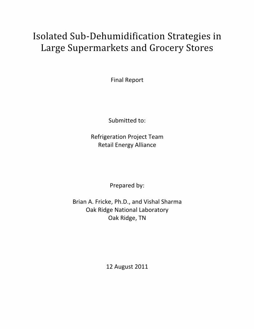
Dual-Path Systems
In a dual-path HVAC system, shown in Figure 3, outside ventilation air is conditioned separately from the
recirculation air. Typically, the outside air is cooled and dehumidified to a low dew point temperature,
9
then mixed with the return air, and finally supplied to the space. Compared to the conventional, single-
path system, the dual path system has improved dehumidification performance at part-load conditions.
Figure 3. Dual-path HVAC system (Khattar 2004)
Desiccant-Based Systems
The use of hybrid HVAC systems that incorporate desiccant dehumidification have been proposed for
supermarket applications (GRI 1984) (Mitchell, et al. 1992) (Capozzoli, et al. 2006) (Lazzarin and
Castellotti 2007). In these desiccant dehumidification HVAC systems, shown in Figure 4, outdoor air
passes over a solid or liquid desiccant that removes the moisture from the air, either by adsorption or
absorption. The dehumidified air then passes over cooling and heating coils and through a humidifier
for final conditioning prior to being discharged into the conditioned space. In order to continually
remove moisture from the supply air, the moisture rich desiccant must be frequently regenerated. This
is done by passing warm air over the desiccant. The warm air absorbs the moisture from the desiccant,
and the desiccant is thereby regenerated and able to remove moisture from the supply air stream. The
warm regeneration air stream is often produced via a gas-fired heater. To increase system efficiency,
waste heat from the supermarket refrigeration system could be used to preheat the regeneration air
stream or to heat the supply air.
Desiccant dehumidification systems have several advantages over that of conventional single-path and
dual-path HVAC systems, including separate control of the latent and sensible heat loads and smaller
cooling system requirements (Capozzoli, et al. 2006). In addition, the smaller cooling requirements of
desiccant systems can be met with cooling systems having a higher COP than that compared to
conventional and dual-path systems. However, desiccant-based systems require a source of heat to
regenerate the desiccant material, and often times this is provided via gas-fired heaters. Thus, while
cooling system capacity may be reduced with a corresponding reduction in electrical energy
consumption, an additional natural gas consumption may be required for desiccant systems.
10
Figure 4. Desiccant-based dehumidification system (Capozzoli, et al. 2006).
Heat Pipe Heat Exchanger Enhancements
In the improved single-path and dual-path HVAC systems described above, the cooling coil temperature
is lower than that which is typically used for traditional commercial applications. By reducing the coil
temperature, the dehumidification capacity of the coil is increased since the dew point temperature of
the air passing through the coil is reduced. However, there is a practical lower limit on the coil
temperature. If the surface temperature of the coil is below 32°F (0°C), then frost will form on the coil.
Frost accumulation will eventually degrade the heat transfer performance of the coil and defrost cycles
are required to remove the frost. Thus, coil temperatures must be maintained above 32°F (0°C) to avoid
frost formation.
A heat pipe is a simple device which can be used to increase the dehumidification performance of air
cooling coils while still maintaining the coil temperature above 32°F (0°C). A heat pipe is a sealed tube
that is partially filled with a volatile working fluid such as a refrigerant. Warm air is passed over the
lower end of the heat pipe which causes the refrigerant in the tube to boil and absorb heat from the
warm air stream, thereby cooling the warm air. The vapor then travels to the higher end of the heat
pipe where it is in contact with a cold air stream. The vapor now condenses, transferring heat from the
refrigerant to the cold air stream, thereby heating the cold air. The condensed refrigerant now flows via
gravity to the lower end of the heat pipe and the cycle repeats. The net effect is to transfer heat from
the warm air stream to the cold air stream.
The two ends of a heat pipe can be placed upstream and downstream of an air cooling coil to precool
the incoming air and reheat the exiting air. By doing so, the total amount of cooling required by the coil
is reduced and thus, a portion of the coil’s sensible capacity is exchanged for additional latent capacity.
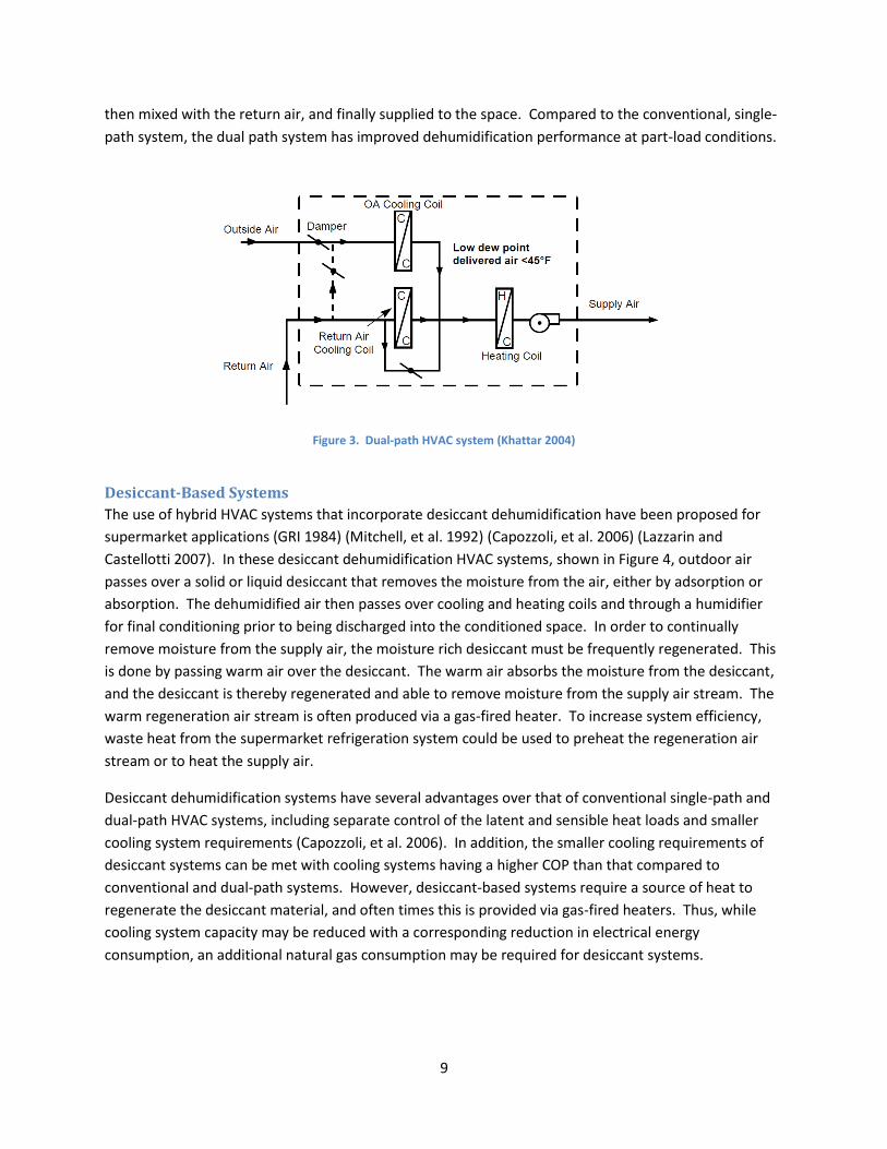
Therefore, heat pipes can increase the dehumidification capacity of air cooling coils.
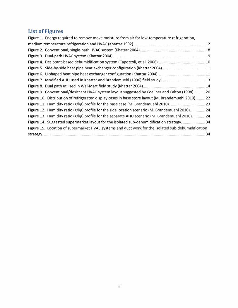
Heat pipes may be used in a side-by-side configuration, as shown in Figure 5. In this configuration, the
lower ends of the heat pipes are located in the inlet air flow path. The higher ends of the heat pipes are
located in the outlet air flow path. The air must change direction 180 degrees in order to pass through
Khattar and Brandemuehl (1996) noted that the HVAC system at the selected field site was undersized.
However, important trends were observed. The heat pipe heat exchangers were found to provide a 28%
improvement in dehumidification efficiency under typical summer operating conditions. Also, a 20%
reduction in airflow produced a 17% improvement in dehumidification efficiency. Furthermore, the
combination of the heat pipe heat exchanger and reduced airflow increased the dehumidification
efficiency of the system by 42%.
In addition, Khattar and Brandemuehl (1996) found that the sensible loads were small compared to
latent loads, which were driven by infiltration. It was estimated that the infiltration into this particular
14
supermarket ranged from 0.11 cfm/ft2 to 0.17 cfm/ft2 (0.56 L/s·m2 to 0.86 L/s·m2). Khattar and
Brandemuehl noted that effective humidity control requires that infiltration and ventilation be
controlled to minimum acceptable levels. They recommend slight pressurization of the space.
Furthermore, Khattar and Brandemuehl (1996) also found that the sensible cooling provided by the
refrigerated display cases was significant such that this particular supermarket did not require any net
cooling until the average daily outdoor temperature exceeded 74°F (23°C).
Khattar (2004) investigated the performance of a dual-path water-source heat pump system in a
supercenter located in Moore, OK. A schematic of the dual path system used in the field demonstration
is shown in Figure 8. This system was used to provide variable ventilation rate through the ventilation
air path, conditioned ventilation air below a set point of 45°F (7°C) at all airflow rates, and space heating
through recovery of refrigeration waste heat from a circulating water loop. This system used a water-
cooled DX coiling coil in the ventilation air path and a water-source heat pump in the recirculation air
path. A central circulating water loop was used in which the waste heat from the refrigeration racks was
transferred to the rooftop HVAC units. Cooling towers were used to reject the excess heat in the water
loop which was not used for space heating.
Figure 8. Dual path utilized in Wal-Mart field study (Khattar 2004).
Khattar (2004) found that this dual path system was capable of maintaining the indoor dew point
between 45°F to 48°F (7°C to 9°C) regardless of outdoor dew point temperature (unless the outdoor
dew point fell below 45°F (7°C), in which case, the indoor dew point also dropped). This corresponds to
approximately 40% to 45% RH at 70°F (21°C). Furthermore, no additional heat was required to maintain
space conditions in the winter other than the heat which was recovered from the water loop. Thus, it
was demonstrated that the refrigeration waste heat could be practically and efficiently used, without
the need for additional heat sources.
Desiccant Systems
Banks (1992) noted several advantages that desiccant systems have to offer as compared to single-path
and dual-path systems. Based on the information from over 200 operating supermarkets, Banks claims
that desiccant dehumidification has lowered operating costs. In addition, the cost effectiveness of the
15
desiccant systems can be further enhanced by utilizing the waste heat from the supermarket
refrigeration system to preheat the regeneration airflow. It was noted that desiccant systems can
maintain the relative humidity as low as 30% at 75°F, with airflow rates as low as 0.5 cfm/ft2 (2.5 L/s per
m2), as compared to dew points of 45°F to 50°F (7°C to 10°C) with airflow rates of 1 cfm/ft2 (5.1 L/s per
m2) for conventional systems. Finally, Banks noted that with desiccant dehumidification, the central air
conditioning is used for sensible cooling only. Thus, central air conditioning capacity can be reduced by
20% to 30%. In addition, central AC evaporator coils can operate at a higher suction pressure, thus
increasing the COP.
On the other hand, Malone (1992) describes experiences with desiccant-based systems which are not
quite as optimistic as those given by Banks (1992). Malone notes that, while desiccant-based systems
can maintain humidity levels at 40%-45%, consideration of first cost and the ongoing maintenance
requirements must be considered. Even though his organization was an early adopter of desiccant
technology, they are now using more cost effective technologies such as heat pipes, dual coil and sub-
cooled reheat concepts. Malone has found that the simple payback for a desiccant-based system can be
10 years or more. In addition, significantly more maintenance is required for desiccant systems as
compared to conventional packaged rooftop units. In terms of first cost and operating costs for
desiccant-based systems, Malone provides the following information:
Compared to a custom, dual-path type supermarket HVAC system designed to maintain 45% RH,
the first cost for a similarly sized desiccant system designed to maintain 40% RH is 37% more
(cost includes system first cost, delivery, installation and ductwork).
Compared to a custom, dual-path type supermarket HVAC system designed to maintain 45% RH,
the annual operating costs (utilities and maintenance) of a similarly sized desiccant system
designed to maintain 40% RH is 14% more.
Compared to a conventional packaged RTU system designed to maintain 45% RH, the first cost
for a similarly sized desiccant system designed to maintain 40% RH is 39% more (includes system
first cost, delivery, installation and ductwork).
Compared to conventional packaged RTU system designed to maintain 45% RH, the annual
operating costs (utilities and maintenance) of a desiccant system designed to maintain 40% RH is
3% less.
Brandemuehl and Khattar (1997) provide data from field monitoring of a desiccant-based system
installed in a 38,427 ft2 New Jersey supermarket. The original HVAC system at this supermarket was a
conventional rooftop DX cooling system which provided cooling and dehumidification. The system
provided 75 tons (265 kW) of cooling and dehumidification capacity with an supply airflow of 28,000 cfm
(13,200 L/s). The system was then retrofitted with an all-electric desiccant dehumidifying system. The
modified system consisted of the original rooftop unit, with reduced airflow (18,000 cfm or 8,494 L/s)
and reduced capacity (45 tons or 158 kW). The desiccant system had a supply air flow rating of
7,000 cfm (3,300 L/s), a regeneration air flow rating of 4,400 cfm (2,080 L/s) and a total fan power of
8.8 kW. Waste heat from the refrigeration system was used to regenerate the desiccant material. The
16
desiccant material that was used in the system was newly developed, and could be effectively
regenerated at temperatures as low as 130°F (54°C).
Two zones were created with the air distribution system: the desiccant system served the freezer aisles
while a conventional DX system served the remainder of the store. Thus, the desiccant system could
focus dehumidification in the freezer aisles where the greatest benefit from dehumidification could be
realized.
Brandemuehl and Khattar (1997) found that the new desiccant-based system was able to maintain a
substantial humidity gradient across the supermarket, where the freezer aisles had a lower humidity
than the main grocery aisles. The humidity gradient was found to disappear as the overall humidity
levels dropped. In addition, the desiccant system heats as well as dehumidifies the supply air. It was
found that the additional heat added to the store did not appear to increase the cooling energy use of
the HVAC system. The heat generally provided beneficial warming to the freezer aisles, improving
occupant comfort. The heat added to the supermarket by the desiccant system was less than the need
for reheat with a conventional HVAC system.
Capozzoli et al. (2006) modeled the variation in energy consumption versus humidity level for a
supermarket that utilized a desiccant dehumidification HVAC system. A schematic of the hybrid system
is shown in Figure 4. The 39,800 ft2 (3,700 m2) prototype supermarket was divided into four zones,
including three peripheral zones (bakery, store and offices) and one core zone (sales center and check-
out area). The three peripheral zones were each serviced by their own individual, traditional HVAC
systems, while the core zone was serviced by a desiccant dehumidification HVAC system. Both a
desiccant wheel hybrid HVAC system and a liquid desiccant hybrid HVAC system were modeled in the
core zone. Furthermore, the energy modeling of the prototype supermarket was performed for three
Italian cities (Bolzano, Rome and Trapani).
For the simulations performed for Rome, Capozzoli et al. (2006) found that, excluding refrigeration, the
electrical energy use of the hybrid systems was 15% to 17% lower than that of the traditional HVAC
system. In addition, natural gas use of the hybrid systems was 1% to 6% lower than that of the
traditional HVAC system. There was a substantial summer reheating and winter dehumidification gas
use by the traditional HVAC system which the hybrid systems did not have, while the hybrid systems had
a regeneration gas usage which the traditional system did not have. Finally, Capozzoli et al. (2006)
found that the overall energy costs (including both electric and gas) for the entire supermarket
(including both HVAC and refrigeration) were 10% to 12% lower for the hybrid systems as compared to
the traditional HVAC system.
Analysis of Several Dehumidification Alternatives
Using computer modeling, Mitchell et al. (1992) investigated the energy impacts of several
dehumidification strategies for supermarket applications. Four HVAC systems were considered,
including:
Conventional (single path) system
Improved single path system
17
Dual path system
Hybrid gas-fired desiccant/vapor compression cycle cooling system
These systems were evaluated for a typical supermarket located in Miami, FL. Annual energy
simulations were performed and operating costs and first costs of the systems were analyzed.
The key findings from the energy simulation studies performed by Mitchell et al. (1992) include the
following:
In Miami, the supermarket HVAC system accounts for approximately 7% to 25% of the total
store energy use.
Lowering the store humidity reduced the supermarket’s total electrical energy use for all but the
conventional HVAC system. Shifting the dehumidification to the HVAC system rather than the
refrigeration system was found to be more efficient since the HVAC compressors have a higher
COP than the refrigeration compressors.
Lowering the store relative humidity from 55% to 40% reduced the refrigeration system energy
use by approximately 20%. This savings included the reduction in frost and anti-sweat heater
operation as well as improved refrigeration system efficiency. The HVAC system energy use
increased as much as 36% to 89% to maintain the lower humidity, but, for the high efficiency
HVAC systems, the overall energy use of the store was reduced by about 6%. However,
maintaining a reduced humidity with the conventional HVAC system increased the total energy
use of the supermarket by 3%.
The dual path and desiccant systems consumed about 10% to 15% less energy as compared to
the conventional system. While the desiccant system used about the same electrical energy as
the dual path system, the desiccant system also required natural gas to reactivate the desiccant.
Compared to the improved single path and dual path systems, desiccant systems had similar
operating costs but significantly higher initial costs.
The heat pipe heat exchanger added little benefit to the single and dual path systems when the
relative humidity was maintained at 55%. However, at 40% RH, the heat pipe heat exchanger
produced a 7% energy benefit for the single path system but little improvement for the dual
path system.
At 40% RH, the energy costs associated with operating the high efficiency HVAC systems were
about 9% to 14% less than that of the conventional HVAC system at 55% RH, and about 12% to
17% less than that of the conventional HVAC system at 40% RH.
The improved single and dual path systems were estimated to cost less than the conventional
system due to the reduced capacity requirements for the air conditioner. Desiccant systems
were estimated to cost 20% to 24% more than the conventional HVAC system. These estimated
installed costs included equipment purchase, installation, wiring, piping and ductwork costs for
each system.
Walker (2001) presents the results of a study in which the energy consumption of a prototypical
supermarket was modeled using various refrigeration and HVAC system configurations. Refrigeration
and HVAC systems studied included conventional rooftop units, refrigeration heat reclaim and water-
18
source heat pumps, as well as multiplex refrigeration with air-cooled condensing and mechanical
subcooling and advanced, low-charge refrigeration systems. The simulations were performed for four
cities in the U.S., including Worcester, MA, Washington, D.C., Memphis, TN and Los Angeles, CA.
Walker (2001) found that a heat reclaim system which incorporated a water-source heat pump HVAC
system had the lowest annual operating costs as compared to the conventional HVAC and heat reclaim
systems. Savings of the water-source heat pump system ranged from 2.2% to 30.7% as compared to the
conventional HVAC system and from 3.8% to 22.1% as compared to the conventional HVAC system with
heat reclaim for space heating. Walker noted that the results were extremely varied and were highly
dependent on the local rates for electricity and natural gas.
Summary Dual path and desiccant HVAC systems which maintain the indoor relative humidity of a supermarket at
40% were estimated to produce electrical energy savings of 10% to 15% as compared to conventional
HVAC systems which maintain the indoor relative humidity at 55%. Retrofitting conventional HVAC
systems with heat pipe heat exchangers was found to reduce the required air conditioning capacity of
the supermarket HVAC units by 14% to 33% while improving the dehumidification efficiency by up to
28%. In addition, dehumidification efficiency can be increased by reducing the air flow rate through
HVAC systems. A 20% reduction in air flow rate was reported to result in a 17% increase in
dehumidification efficiency for a dual path HVAC system with heat pipe heat exchangers (Khattar and
Brandemuehl 1996).
Desiccant systems were reported to maintain low humidity levels within supermarkets, on the order of
30% to 35%, with low air flow rates of approximately 0.5 cfm/ft2 (2.5 L/s per m2). In addition,
supermarket air conditioning capacity requirements are reduced by 20% to 40% with desiccant systems.
However, desiccant systems require a heat source in order to regenerate the desiccant material. This
regeneration heat may be partially or fully supplied by waste heat from the supermarket’s refrigeration
system. Nonetheless, one study suggested that the natural gas use of a desiccant-based system can be
1% to 6% less than that of a conventional HVAC system (Capozzoli, et al. 2006).
Advanced HVAC systems that incorporate water-source heat pumps have been investigated (Walker
2001) (Khattar 2004). These systems use water loops to recover waste heat from the supermarket
refrigeration system and transfer that energy to heat pump which can supply heating and cooling to the
supermarket. No additional heat sources are required by these systems, and compared to conventional
HVAC systems, energy savings of 2% to 31% may be achieved.
Operating costs of these various HVAC options have been found to vary widely with local rates for
electricity and natural gas (Walker 2001). Thus, local utility rates must be considered when selecting
cost-effective HVAC equipment for supermarket applications.
19
5. Whole Store Dehumidification vs. Isolated Sub-Dehumidification Based on the assumption that the area near refrigerated display cases requires humidity control in order
to obtain efficient performance from the refrigeration system while the dry goods sales area generally
requires no humidity control, it has been proposed to maintain the refrigerated display case area at a
lower humidity than the dry goods sales area. The effectiveness of this technique depends upon how
fast moisture will diffuse through the air and migrate to the refrigerated display case area if the
humidity in the dry goods area is higher than that in the refrigerated display case area. A few analytical
and field studies have been performed to determine the feasibility of isolated sub-dehumidification
strategies versus whole-store dehumidification strategies.
Early Studies A US patent (no. 5,749,230) has been issued for the concept of isolated sub-dehumidification using a
combination of conventional HVAC and desiccant dehumidification units to supply varying levels of
humidity to different regions within a single-zone space, such as that typically found in supermarkets
(Coellner and Calton 1998).
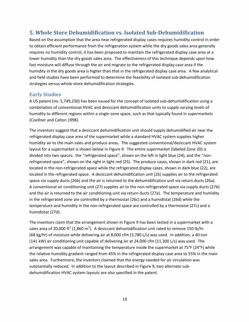
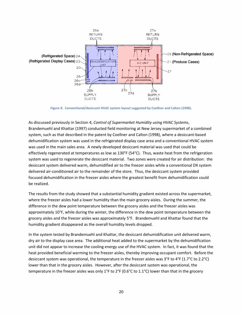
The inventors suggest that a desiccant dehumidification unit should supply dehumidified air near the
refrigerated display case area of the supermarket while a standard HVAC system supplies higher
humidity air to the main sales and produce areas. The suggested conventional/desiccant HVAC system
layout for a supermarket is shown below in Figure 9. The entire supermarket (labeled Zone 20) is
divided into two spaces: the “refrigerated space”, shown on the left in light blue (24), and the “non-
refrigerated space”, shown on the right in light red (25). The produce cases, shown in dark red (21), are
located in the non-refrigerated space while the refrigerated display cases, shown in dark blue (22), are
located in the refrigerated space. A desiccant dehumidification unit (26) supplies air to the refrigerated
space via supply ducts (26b) and the air is returned to the dehumidification unit via return ducts (26a).
A conventional air conditioning unit (27) supplies air to the non-refrigerated space via supply ducts (27b)
and the air is returned to the air conditioning unit via return ducts (27a). The temperature and humidity
in the refrigerated zone are controlled by a thermostat (26c) and a humidistat (26d) while the
temperature and humidity in the non-refrigerated space are controlled by a thermostat (27c) and a
humidistat (27d).
The inventors claim that the arrangement shown in Figure 9 has been tested in a supermarket with a
sales area of 20,000 ft2 (1,860 m2). A desiccant dehumidification unit rated to remove 150 lb/hr
(68 kg/hr) of moisture while delivering air at 8,000 cfm (3,780 L/s) was used. In addition, a 40-ton
(141 kW) air conditioning unit capable of delivering air at 24,000 cfm (11,300 L/s) was used. The
arrangement was capable of maintaining the temperature inside the supermarket at 75°F (24°F) while
the relative humidity gradient ranged from 45% in the refrigerated display case area to 55% in the main
sales area. Furthermore, the inventors claimed that the energy needed for air circulation was
substantially reduced. In addition to the layout described in Figure 9, two alternate sub-
dehumidification HVAC system layouts are also specified in the patent.
20
Figure 9. Conventional/desiccant HVAC system layout suggested by Coellner and Calton (1998).
As discussed previously in Section 4, Control of Supermarket Humidity using HVAC Systems,
Brandemuehl and Khattar (1997) conducted field monitoring at New Jersey supermarket of a combined
system, such as that described in the patent by Coellner and Calton (1998), where a desiccant-based
dehumidification system was used in the refrigerated display case area and a conventional HVAC system
was used in the main sales area. A newly developed desiccant material was used that could be
effectively regenerated at temperatures as low as 130°F (54°C). Thus, waste heat from the refrigeration
system was used to regenerate the desiccant material. Two zones were created for air distribution: the
desiccant system delivered warm, dehumidified air to the freezer aisles while a conventional DX system
delivered air-conditioned air to the remainder of the store. Thus, the desiccant system provided
focused dehumidification in the freezer aisles where the greatest benefit from dehumidification could
be realized.
The results from the study showed that a substantial humidity gradient existed across the supermarket,
where the freezer aisles had a lower humidity than the main grocery aisles. During the summer, the
difference in the dew point temperature between the grocery aisles and the freezer aisles was
approximately 10°F, while during the winter, the difference in the dew point temperature between the
grocery aisles and the freezer aisles was approximately 5°F. Brandemuehl and Khattar found that the
humidity gradient disappeared as the overall humidity levels dropped.
In the system tested by Brandemuehl and Khattar, the desiccant dehumidification unit delivered warm,
dry air to the display case area. The additional heat added to the supermarket by the dehumidification
unit did not appear to increase the cooling energy use of the HVAC system. In fact, it was found that the
heat provided beneficial warming to the freezer aisles, thereby improving occupant comfort. Before the
desiccant system was operational, the temperature in the freezer aisles was 3°F to 4°F (1.7°C to 2.2°C)
lower than that in the grocery aisles. However, after the desiccant system was operational, the
temperature in the freezer aisles was only 1°F to 2°F (0.6°C to 1.1°C) lower than that in the grocery
21
aisles. Furthermore, the heat added to the supermarket by the desiccant dehumidification unit was less
than that which would have been required for reheat with a conventional HVAC system.
Since the desiccant dehumidification system used waste heat from the refrigeration system to
regenerate the desiccant material, the only purchased energy required to operate the system was
associated with the fans. Compared to a well-designed conventional HVAC system, Brandemuehl and
Khattar found that the desiccant dehumidification system was approximately three to four times more
efficient at removing moisture. Furthermore, Brandemuehl and Khattar reported that a slight reduction
in refrigeration system energy consumption was noted when the desiccant dehumidification system was
in operation.
Recent Studies Recently, several modeling studies have been performed to determine the effect of humidity level on
supermarket energy consumption.
It has been found that dehumidifying an entire supermarket with a desiccant-based HVAC system may
not be cost effective (Walker 2001). Thus, based upon this experience, some supermarket chains limit
the use of desiccant systems, or other low humidity HVAC systems, to the refrigerated display case areas
of the supermarket where lower humidity levels are beneficial. It has been reported that desiccant-
based systems work well in this application because they deliver warm, dry air directly into the
refrigerated food aisles, which helps offset the overcooling produced by the display cases. The drying of
the air is limited to the vicinity of the low temperature refrigerated cases, where maximum benefit to
the refrigerated cases is obtained (Walker 2001).
As discussed previously in Section 4, Control of Supermarket Humidity using HVAC Systems, Capozzoli et
al. (2006) modeled the variation in energy consumption versus humidity level for a supermarket that
utilized a desiccant dehumidification HVAC system. The 39,800 ft2 (3,700 m2) prototype supermarket
was divided into four zones, including three peripheral zones (bakery, store and offices) and one core
zone (sales center and check-out area). The three peripheral zones were each serviced by their own
individual, traditional HVAC systems, while the core zone was serviced by a desiccant dehumidification
HVAC system. Both a desiccant wheel hybrid HVAC system and a liquid desiccant hybrid HVAC system
were modeled in the core zone. Furthermore, the energy modeling of the prototype supermarket was
performed for three Italian cities (Bolzano, Rome and Trapani).
The simulation results indicated that a total operating cost savings of between 5% to 13%, depending
upon the climatic conditions, could be achieved by using a hybrid system rather than a traditional HVAC
system in the central zone. These cost savings estimates include both electric and gas usage. In
addition, for the city of Rome, it was found that the electrical energy consumption of the refrigeration
system could be reduced by 11% to 12% by using a hybrid HVAC system. Similar results were noted for
the other cities studied (Bolzano and Trapani). A simple payback of approximately 1 year was estimated
for the hybrid HVAC system.
While the simulations performed by Capozzoli et al. (2006) modeled the supermarket as four zones, with
traditional HVAC systems in the peripheral zones and a hybrid system in the central zone, this
22
configuration is not necessarily the same as that in which the refrigerated display cases are serviced by a
dehumidification unit while the remainder of the store is serviced by traditional HVAC. However, the
results show that it could be beneficial to dehumidify only certain portions of the supermarket.
An on-going project funded by the American Society of Heating, Refrigerating and Air-Conditioning
Engineers (ASHRAE), Research Project 1467-RP, “Balancing Latent Heat Load between Display Cases and
Store Comfort Cooling,” is being conducted to optimize the design and operation of the combined HVAC
and refrigeration systems of supermarkets. The researchers have reported preliminary results regarding
the effect of refrigerated display case spatial distribution on supermarket humidity profiles (M.
Brandemuehl 2010).
In this project, a prototypical 48,400 ft2 (4,500 m2) supermarket was developed and the effect of
refrigerated display case distribution on the supermarket humidity profile was determined using
computational fluid dynamics (CFD). The basic layout of the prototype supermarket is shown in Figure
10 (M. Brandemuehl 2010). The front of the store is at the top of Figure 10 and the refrigerated display
cases, shown as grey rectangles, are generally distributed around the perimeter of the store.
Figure 10. Distribution of refrigerated display cases in base store layout (M. Brandemuehl 2010)
The following four scenarios were modeled:
1. Base Case: A single air handler delivered supply air near the front of the store (top of Figure 10)
and removed return air at the rear of the store.
2. Side Location: Same as the Base Case, but the refrigerated display cases were redistributed to
be on one side of the store.
3. Scattered Location of Cases: Same as the Base Case, but the refrigerated display cases were
scattered throughout the store.
23
4. Separate AHUs: Base Case layout with two separate air handling units that delivered different
supply streams to the freezer area and the main sales area. The air handler in the freezer area
supplied air at a lower humidity.
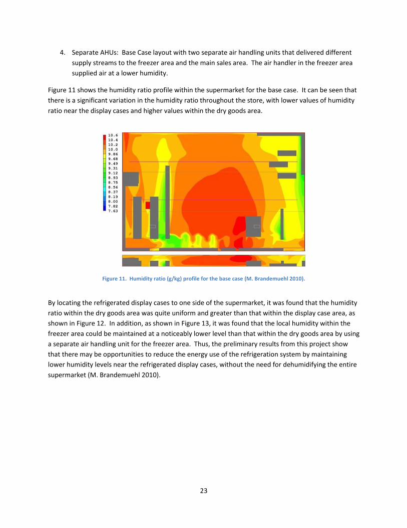
Figure 11 shows the humidity ratio profile within the supermarket for the base case. It can be seen that
there is a significant variation in the humidity ratio throughout the store, with lower values of humidity
ratio near the display cases and higher values within the dry goods area.
Figure 11. Humidity ratio (g/kg) profile for the base case (M. Brandemuehl 2010).
By locating the refrigerated display cases to one side of the supermarket, it was found that the humidity
ratio within the dry goods area was quite uniform and greater than that within the display case area, as
shown in Figure 12. In addition, as shown in Figure 13, it was found that the local humidity within the
freezer area could be maintained at a noticeably lower level than that within the dry goods area by using
a separate air handling unit for the freezer area. Thus, the preliminary results from this project show
that there may be opportunities to reduce the energy use of the refrigeration system by maintaining
lower humidity levels near the refrigerated display cases, without the need for dehumidifying the entire
supermarket (M. Brandemuehl 2010).
24
Figure 12. Humidity ratio (g/kg) profile for the side location scenario (M. Brandemuehl 2010).
Figure 13. Humidity ratio (g/kg) profile for the separate AHU scenario (M. Brandemuehl 2010).
Summary Several researchers have proposed the use of isolated sub-dehumidification in which dehumidified air is
delivered to the refrigerated display case aisles while higher humidity air is delivered to the remainder
of the supermarket area. It appears that this technique has merit and it is possible to maintain a
humidity gradient throughout the store, with lower humidity levels in the refrigerated display case aisles
and higher humidity levels in the remainder of the supermarket. Rather than maintaining the humidity
of the entire supermarket at a lower level, it may be more cost effective to maintain only the
refrigerated display case area at a lower humidity level.
25
6. Estimated Energy and Cost Savings of Isolated Sub-Dehumidification As shown by Coellner and Calton (1998), Brandemuehl and Khattar (1997) and Brandemuehl (2010), it
appears that the concept of isolated sub-dehumidification within is supermarket is feasible and it is
possible to maintain a humidity gradient across the store. Thus, in this project, estimates have been
made to determine the energy and cost savings associated with implementing isolated sub-
dehumidification.
Two major systems are impacted by the implementation of isolated sub-dehumidification in a
supermarket: the refrigeration system and the HVAC system. The estimated energy savings associated
with each of these systems will be discussed below.
Refrigeration System Energy Savings In order to estimate the energy savings associated with reducing the relative humidity within a
supermarket, a prototypical supermarket was developed, based on the information provided by
Westphalen et al. (1996). The prototypical supermarket has a plan area of 45,000 ft2 and the
refrigeration system for the supermarket consists of two medium temperature racks and two low
temperature racks.
The medium temperature racks supply refrigeration to open, multi-deck cases and walk-in coolers while
the low temperature racks supply refrigeration to reach-in (doored) freezer cases, coffin cases and walk-
in freezers. The specifications of the refrigerated display cases and walk-in coolers/freezers used in the
prototype store are given in Table 2 (Westphalen, et al. 1996). The refrigerated display cases and walk-
in coolers/freezers are assumed to operate in a supermarket whose space conditions are maintained at
75°F (23.9°C), 55% relative humidity. Note that these conditions correspond to the rating conditions
specified in ASHRAE Standard 72 for testing commercial refrigerators and freezers (ANSI/ASHRAE 2005).
The baseline refrigeration load of the medium temperature display cases and walk-in coolers is
750,000 Btu/hr at 55% RH, while the baseline refrigeration load of the low temperature display cases
and walk-in freezers is 300,000 Btu/hr at 55% RH.
26
Table 2. Specifications of Refrigerated Display Cases and Walk-In Coolers/Freezers (Westphalen, et al. 1996).
Temperature Range
Display Case/Walk-In
Length (ft) or Area (ft2)
Baseline Load (Btu/hr·ft or Btu/hr·ft2)
Baseline Total Load (Btu/hr)
Medium
Multi-deck cases, meat
120 ft 1500 Btu/hr·ft 180,000
Multi-deck cases, other
260 ft 1500 Btu/hr·ft 390,000
Walk-in cooler, meat
400 ft2 60 Btu/hr·ft2 26,000
Walk-in cooler, other
2,600 ft2 60 Btu/hr·ft2 154,000
Total, medium temperature: 750,000
Low
Reach-in cases 268 ft 560 Btu/hr·ft 150,000
Coffin cases 128 ft 550 Btu/hr·ft 70,000
Walk-in freezer 1,000 ft2 80 Btu/hr·ft2 80,000
Total, low temperature: 300,000
The specifications of the baseline medium temperature and low temperature refrigeration racks are
given in Table 3 (Westphalen, et al. 1996). Assuming a coefficient of performance (COP) of 2.5 for the
medium temperature refrigeration system, a compressor power of 88 kW is required to satisfy the
medium temperature loads. Similarly, assuming a COP of 1.3 for the low temperature refrigeration
system, a compressor power of 68 kW is required to satisfy the low temperature loads.
Table 3. Baseline Compressor Rack Specifications (Westphalen, et al. 1996).
Compressor Rack
Saturated Suction
Temperature (°F)
Saturated Discharge
Temperature (°F)
System COP Evaporator
Load (Btu/hr)
Compressor Power (kW)
Heat Rejection (Btu/hr)
Medium Temperature (2 racks)
15 115 2.5 750,000 88 1,050,000
Low Temperature (2 racks)
-25 110 1.3 300,000 68 351,000
Totals 1,050,000 156 1,581,000
Based on the information provided in Section 3, Effects of Humidity on Supermarket Refrigeration
Systems, estimates were made for the electrical energy savings of the compressors, defrost heaters and
anti-sweat heaters, associated with reducing the supermarket relative humidity from 55% to 35%.
These electrical energy savings estimates are given in Table 4.
27
Table 4. Estimated Compressor, Defrost Heater and Anti-Sweat Heater Electrical Energy Savings for Various Refrigerated Display Cases.
Case Type Compressor
Electrical Energy Savings (%)
Defrost Electrical Energy
Savings (%)
Anti-Sweat Heater Electrical Energy Savings
(%)
Multi-deck, meat (medium temperature)
20 25 67
Multi-deck, other (medium temperature)
20 0 0
Reach-in (low temperature) 3 5 67
Coffin (low temperature) 12 5 67
As shown in Table 5, the compressor electrical energy savings was used to estimate the reduction in the
refrigeration load as a function of relative humidity. It can be seen that the medium temperature rack
load decreased from 750,000 Btu/hr at 55% RH to 636,000 Btu/hr at 35 %RH. Similarly, the low
temperature rack load decreased from 300,000 Btu/hr at 55% RH to 287,600 Btu/hr at 35% RH. In the
analysis, it was assumed that reduced humidity levels in the supermarket did not affect the performance
of the walk-in coolers and freezers.
Table 5. Reduction in Display Case Load due to Reduction in Relative Humidity.
Temperature Range
Display Case/Walk-In
Baseline Total Load, 55% RH (Btu/hr)
Total Load, 35% RH (Btu/hr)
Medium
Multi-deck cases, meat
180,000 144,000
Multi-deck cases, other
390,000 312,000
Walk-in cooler, meat
24,000 24,000
Walk-in cooler, other
154,000 156,000
Total 750,000 636,000
Low
Reach-in cases 150,000 145,600
Coffin cases 70,000 62,000
Walk-in freezer 80,000 80,000
Total 300,000 287,600
The corresponding reduction in the compressor rack power requirements is given in Table 6. It can be
seen that reducing the supermarket relative humidity from 55% to 35% reduced the total compressor
power from 156 kW to 140 kW. In addition, the condenser heat rejection was reduced from
1,581,000 Btu/hr to 1,401,300 Btu/hr.
28
Table 6. Reduction in Compressor Rack Power Requirements due to Reduction in Relative Humidity.
Compressor Rack
System COP
Baseline Evaporator
Load, 55% RH (Btu/hr)
Baseline Compressor
Power, 55% RH (kW)
Evaporator Load, 35% RH,
(Btu/hr)
Compressor Power, 35% RH
(kW)
Medium temperature
2.5 750,000 88 636,000 75
Low temperature
1.3 300,000 68 287,600 65
Total 1,050,000 156 923,600 140
The reduction in electrical energy consumption of the medium temperature refrigerated display case
accessories, consisting of evaporator fans, anti-sweat heaters, defrost heaters and lights, is shown in
Table 7 while that for the low temperature display cases is shown in Table 8. The electrical energy
consumption of the medium temperature display case accessories was reduced from 129,600 kWh/yr at
55% RH to 120,600 kWh/yr at 35% RH. For the low temperature display cases, the electrical energy
consumption of the accessories was reduced from 348,200 Btu/hr at 55% RH to 221,700 Btu/hr at
35% RH.
Table 7. Reduction in Medium Temperature Display Case Electrical Energy Consumption due to Reduction in Relative Humidity (Westphalen, et al. 1996).
Case Type
Component
Baseline Power
Consumption per foot (W/ft)
Baseline Total Power
Consumption (kW)
Duty Cycle (%)
Baseline Energy
Consumption, 55% RH
(kWh/yr)
Estimated Energy
Consumption, 35% RH
(kWh/yr)
Multi-deck, meat (120 ft)
Evaporator fans
26.7 3.2 100 28,000 28,000
Anti-sweat heaters
20 2.4 50 10,500 3,500
Electric defrost heaters
135 16.2 5.6 7,900 5,900
Lights 11.8 1.4 100 12,300 12,300
Subtotal 58,700 49,700
Multi-deck, other (260 ft)
Evaporator fans
12.5 3.3 100 28,900 28,900
Lights 18.3 4.8 100 42,000 42,000
Subtotal 70,900 70,900
Total 129,600 120,600
29
Table 8. Reduction in Low Temperature Display Case Electrical Energy Consumption due to Reduction in Relative Humidity (Westphalen, et al. 1996).
Case Type
Component
Baseline Power
Consumption per foot (W/ft)
Baseline Total Power
Consumption (kW)
Duty Cycle (%)
Baseline Energy
Consumption, 55% RH
(kWh/yr)
Estimated Energy
Consumption, 35% RH
(kWh/yr)
Reach-in (268 ft)
Evaporator fans
20 5.36 96 45,100 45,100
Anti-sweat heaters
71 19 96 159,800 52,700
Electric defrost heaters
400 107 2 18,700 17,800
Lights 33 8.8 100 77,100 77,100
Subtotal 300,700 192,700
Coffin (128 ft)
Evaporator fans
10 1.28 100 11,200 11,200
Anti-sweat heaters
24 3.07 100 26,900 8,900
Electric defrost heaters
420 53.8 2 9,400 8,900
Lights 0 0 0 0
Subtotal 47,500 29,000
Total 348,200 221,700
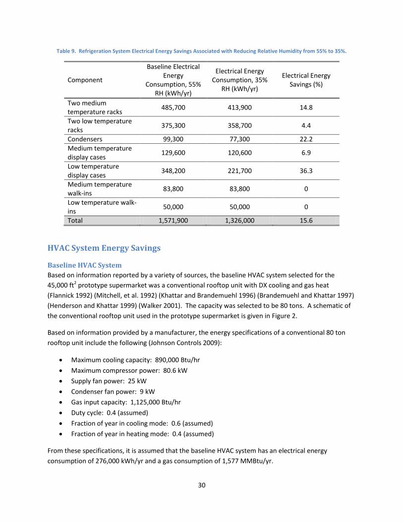
Finally, the reduction in the total refrigeration system electrical energy consumption associated with
reducing the relative humidity from 55% to 35% is summarized in Table 9. It can be seen that the total
refrigeration system electrical energy use was reduced from 1,571,900 kWh/yr to 1,326,000 kWh/yr,
corresponding to an annual savings of 15.6%, when the relative humidity was reduced from 55% to 35%.
Note that this energy savings agrees fairly well with statements made by Capozzoli et al. (2006) and
Getu and Bansal (2006) in which the total refrigeration system energy consumption is reported to
decrease by approximately 1% for every 1% reduction in store relative humidity.
Assuming an average cost of $0.103 per kWh for electricity, the electrical energy cost savings for the
refrigeration system, associated with reducing the humidity from 55% to 35%, is $25,328 per year (EIA
2011).
30
Table 9. Refrigeration System Electrical Energy Savings Associated with Reducing Relative Humidity from 55% to 35%.
Component
Baseline Electrical Energy
Consumption, 55% RH (kWh/yr)
Electrical Energy Consumption, 35%
RH (kWh/yr)
Electrical Energy Savings (%)
Two medium temperature racks
485,700 413,900 14.8
Two low temperature racks
375,300 358,700 4.4
Condensers 99,300 77,300 22.2
Medium temperature display cases
129,600 120,600 6.9
Low temperature display cases
348,200 221,700 36.3
Medium temperature walk-ins
83,800 83,800 0
Low temperature walk-ins
50,000 50,000 0
Total 1,571,900 1,326,000 15.6
HVAC System Energy Savings
Baseline HVAC System
Based on information reported by a variety of sources, the baseline HVAC system selected for the
45,000 ft2 prototype supermarket was a conventional rooftop unit with DX cooling and gas heat
(Flannick 1992) (Mitchell, et al. 1992) (Khattar and Brandemuehl 1996) (Brandemuehl and Khattar 1997)
(Henderson and Khattar 1999) (Walker 2001). The capacity was selected to be 80 tons. A schematic of
the conventional rooftop unit used in the prototype supermarket is given in Figure 2.
Based on information provided by a manufacturer, the energy specifications of a conventional 80 ton
rooftop unit include the following (Johnson Controls 2009):
Maximum cooling capacity: 890,000 Btu/hr
Maximum compressor power: 80.6 kW
Supply fan power: 25 kW
Condenser fan power: 9 kW
Gas input capacity: 1,125,000 Btu/hr
Duty cycle: 0.4 (assumed)
Fraction of year in cooling mode: 0.6 (assumed)
Fraction of year in heating mode: 0.4 (assumed)
From these specifications, it is assumed that the baseline HVAC system has an electrical energy
consumption of 276,000 kWh/yr and a gas consumption of 1,577 MMBtu/yr.
31
Isolated Sub-Dehumidification System
One potential method for achieving isolated sub-dehumidification in a supermarket could include the
use of a desiccant dehumidification unit to supply dry air to the refrigerated display case area of the
supermarket, and a conventional rooftop unit with DX cooling and gas heat to supply conditioned air to
the remainder of the sales area.
In the proposed system, which is similar to the system investigated by Brandemuehl and Khattar (1997),
it was assumed that the heat required to regenerate the desiccant would be supplied by the waste heat
from the refrigeration system and no additional heat would be required. In addition, it was assumed
that the desiccant dehumidification unit would supply 7,000 cfm of warm, dry air to the refrigerated
display case area. The specifications of the desiccant system are as follows:
Supply air flow rate: 7,000 cfm
Supply fan power: 1.14 kW
Regeneration fan flow rate: 2,331 cfm
Regeneration fan power: 0.40 kW
Assuming a duty cycle of 0.4, the annual energy consumption of the desiccant dehumidification system
would be 5,388 kWh per year.
The capacity of the conventional rooftop unit will be less than that required in the baseline case. Thus,
the unit capacity for the rooftop unit was selected to be 50 tons. Based on information provided by a
manufacturer, the energy specifications of a conventional 50 ton rooftop unit include the following
(Johnson Controls 2009):
Maximum cooling capacity: 540,000 Btu/hr
Maximum compressor power: 54.0 kW
Supply fan power: 11.3 kW
Condenser fan power: 2 kW
Gas input capacity: 300,000 Btu/hr
Duty cycle: 0.4 (assumed)
Fraction of year in cooling mode: 0.6 (assumed)
Fraction of year in heating mode: 0.4 (assumed)
From these specifications, it is assumed that the conventional rooftop HVAC system for the isolated sub-
dehumidification strategy has an electrical energy consumption of 141,400 kWh/yr and a gas
consumption of 420 MMBtu/yr.
32
Comparison of Baseline and Isolated Sub-Dehumidification HVAC Strategies
The estimated electrical energy savings associated with isolated sub-dehumidification is:
kWh/yr000,129
kWh/yr400,141kWh/yr388,5kWh/yr000,276
dehumidbaselinesave EEE
(1)
which represents a savings of 53%. In addition, the estimated gas energy savings associated with
isolated sub-dehumidification is:
MMBtu/yr1,157
MMBtu/yr420MMBtu/yr577,1
dehumidbaselinesave GGG
(2)
which represents a savings of 27%.
Assuming an average cost of $0.103 per kWh for electricity and assuming 1 cubic foot of natural gas is
equivalent to 1,027 Btu with an average price for natural gas of $14.62 per thousand cubic feet, it is
estimated that the annual cost of operating the baseline HVAC system and the isolated sub-
dehumidification HVAC system are as follows (EIA 2011):
Thus, the annual HVAC system operating cost savings associated with the proposed isolated sub-
dehumidification strategy is $30,335. This represents an annual HVAC system operating cost savings of
60% as compared to the conventional HVAC system.
Summary of Refrigeration and HVAC System Energy Use and Operating Cost In summary, for the prototypical 45,000 ft2 supermarket, the refrigeration system electrical energy
savings associated with reducing the relative humidity from 55% to 35% was found to be
245,900 kWh/year. Furthermore, by implementing an isolated sub-dehumidification HVAC system
strategy to achieve a reduced relative humidity in the refrigerated display case area, it was found that
the electrical energy savings of the HVAC system was 129,000 kWh/year and the gas energy savings of
the HVAC system was 1,157 MMBtu/year as compared to a conventional HVAC system strategy. Thus,
the total energy savings associated with isolated sub-dehumidification is:
Total Electrical Energy Savings: 374,900 kWh/year (20% savings)
Total Gas Energy Savings: 1,157 MMBtu/year (27% savings)
By implementing an isolated sub-dehumidification HVAC system strategy, it is estimated that a 20%
savings in refrigeration and HVAC system electrical energy can be realized. Furthermore, a 27% savings
in gas energy consumption can be obtained. For the prototypical 45,000 ft2 supermarket investigated in
33
this project, the annual operating cost of the refrigeration and HVAC system could be reduced by
$55,663 through the implementation of an isolated sub-dehumidification HVAC system strategy.
7. Implementation Isolated sub-dehumidification in supermarkets may be implemented in either new construction or in
retrofit applications.
New Construction During the design of a new supermarket, it is recommended that a “refrigerated display case zone” be
created in the supermarket, in which the refrigerated display cases, and especially the low temperature
display cases, are located in the same general area of the supermarket. This “refrigerated display case
zone” will be supplied with lower humidity air. However, it is suggested that the refrigerated fresh
produce display cases should not be located in this refrigerated display case zone since the lower
humidity will tend to dehydrate and wilt the produce. For best results, the fresh produce cases should
be located on the opposite side of the supermarket from the refrigerated display case zone, in the
“general sales area zone” which has a higher humidity level.
Figure 14 shows the suggested floor plan of a hypothetical supermarket utilizing the isolated sub-
dehumidification strategy and illustrates the distribution of low- and medium-temperature refrigerated
display cases which creates a “refrigerated display case zone”. Also shown is the “general sales area
zone” which contains the refrigerated fresh produce cases as well as the canned and dry goods. Note
that the majority of the medium-temperature and low-temperature refrigerated display cases are
located in or near the “refrigerated display case zone” while the fresh produce cases are located on the
opposite side of the supermarket in the “general sales area zone”.
Figure 15 shows the suggested layout for the supermarket HVAC systems and the associated duct work.
The system labeled “HVAC 1” and its associated duct work supplies lower humidity air to the
“refrigerated display case zone”, which includes the frozen food display cases, the deli/diary/beverage
display cases and the fresh meat display cases. The system labeled “HVAC 2” and its associated duct
work supplies higher humidity air to the “general sales area zone”, which includes the fresh produce
display cases as well as the canned and dry goods.
34
Figure 14. Suggested supermarket layout for the isolated sub-dehumidification strategy.
Figure 15. Location of supermarket HVAC systems and duct work for the isolated sub-dehumidification strategy.
35
To create the lower humidity environment within the refrigerated display case zone, several different
technologies may be employed. A desiccant dehumidification unit can be used to supply less humid air
directly to the refrigerated display case zone. This air may or may not be cooled prior to introducing it
to the refrigerated display case zone. In fact, warm, dry air from the desiccant dehumidification unit
may provide beneficial heating to the refrigerated display case aisles, thereby improving the comfort of
the shoppers in the display case aisles and eliminating the need to cool the dehumidified air prior to
supplying it to the refrigerated display case zone. To improve the energy efficiency of the desiccant
dehumidification unit, waste heat from the refrigeration system may be used to preheat the air stream
which is used to regenerate the desiccant.
Other HVAC system options for the refrigerated display case zone include the use of technologies such
as advanced single path systems or dual path systems. In addition, these systems may utilize heat pipe
heat exchangers to enhance dehumidification performance. Single path or dual path systems can
effectively produce conditioned dry air that can be supplied to the refrigerated display case aisles.
Furthermore, these systems can take advantage of the waste heat from the refrigeration system to
reheat the air prior to introducing it into the refrigerated display case zone.
The air supplied to the general sales area zone can be of higher humidity, supplied by standard rooftop
HVAC systems. Since higher humidity levels can be tolerated in the general sales area, and can even be
beneficial for the refrigerated fresh produce cases, specialized HVAC equipment is not necessarily
required in this zone. This aids in lowering the initial cost of the supermarket since traditional HVAC
equipment is typically less expensive than the advanced HVAC systems for humidity control. Therefore,
using standard rooftop units for the main sales area may keep initial costs lower as compared to using
advanced humidity control systems for the entire supermarket.
As noted several studies, the air flow rate of the dehumidified air can be lower than that which is
typically supplied by standard HVAC units. Thus an energy savings benefit can be realized by reducing
the speed of the air supply fans. For example, the air flow for desiccant systems can be as low as
0.5 cfm per cubic foot of refrigerated display case zone floor area (Banks 1992) (Khattar and
Brandemuehl 1996). However, others have noted that it may be beneficial to supply as much as 5 cfm
of dehumidified air per cubic foot of refrigerated display case zone floor area (NYC WasteLess n.d.)
(Desert Aire 2009).
Note that while Figure 15 shows only one HVAC unit in the refrigerated display case zone and in the
general sales area zone, multiple units may be required to meet the supermarket’s heating and cooling
loads, depending upon the size of the store.
To maximize the energy savings which can be obtained by implementing the isolated sub-
dehumidification strategy, it is suggested that energy efficient display cases be used in the refrigerated
display case zone. This includes specifying doored display cases for both the low-temperature and
medium-temperature applications. In addition, since the humidity in the refrigerated display case zone
will be relatively lower, dew point controllers can be used to reduce the energy consumption of the
display case anti-sweat heaters. In some instances, if the humidity level in the refrigerated display case
36
zone is low enough, e.g., around 35%, then anti-sweat heaters may be unnecessary. Furthermore, LED
display case lighting which is controlled with motion sensors will significantly reduce the electrical load
and heat load of the refrigerated display cases. A high efficiency doored display case which incorporates
anti-sweat heater control and LED lighting may reduce the electrical energy consumption by as much as
50% compared to a standard doored display case with continuously operating anti-sweat heaters and
fluorescent lighting (Fricke and Becker 2011).
Retrofit Applications In retrofit applications, the feasibility of implementing the isolated sub-dehumidification strategy is
related to the level of retrofit which may be required. If the supermarket owner is considering a
substantial whole-store remodel, then application of the isolated sub-dehumidification strategy may be
attractive and cost effective. On the other hand, the pre-existing layout of the supermarket may hinder
the implementation of isolated sub-dehumidification if funds are limited and/or only minor retrofits are
planned.
The optimum candidate for an isolated sub-dehumidification retrofit would be a supermarket with a
display case distribution similar to that shown in Figure 14. That is, the majority of the refrigerated
display cases should be located along one side of the supermarket. Another factor to consider is the
location of the existing HVAC units. The optimal retrofit scenario consists of one or more existing HVAC
units that are located near the display case area so that they may be easily replaced with advanced
dehumidification units. In addition, minimal modification of duct work would be desirable.
Note that if the refrigerated display cases, and especially the frozen food cases, are located in center of
store, it would be very difficult to maintain a humidity gradient within the store. An isolated sub-
dehumidification strategy would not be feasible with such a supermarket layout. Only if the display
cases are moved to one side of the store would implementation of the isolated sub-dehumidification
strategy be successful. Thus, in the situation where the display cases are located in the center of the
store, the best approach would be to reduce the humidity of the entire store rather than to implement
the isolated sub-dehumidification strategy.
As noted above for new construction applications, to maximize the energy savings which can be
obtained by implementing the isolated sub-dehumidification in retrofit applications, the store owner
may consider replacing older inefficient display cases with newer more energy efficient models.
8. Conclusions The objective of this project was to determine the potential energy savings associated with reducing the
relative humidity in the vicinity of refrigerated display cases in supermarkets, as compared to the widely
accepted current practice of maintaining a relatively high and uniform humidity level throughout the
entire supermarket. Existing and new strategies for maintaining lower relative humidity levels near the
vicinity of refrigerated display cases were analyzed to determine their effectiveness.
37
Reducing the relative humidity within a supermarket can reduce the energy consumption of the
supermarket’s refrigeration system, including the energy consumption of compressors, defrost heaters
and anti-sweat heaters. The refrigeration system energy savings is dependent upon refrigerated case
type and refrigeration system temperature level. Lower humidity levels significantly improve the
performance of open display cases while the benefit for doored display cases is minor. However, for
doored display cases, a substantial reduction in anti-sweat heater energy requirements can be realized
with lower humidity levels.
For medium temperature refrigeration systems, refrigeration system energy use decreases anywhere
from 15% to 22% when the relative humidity is reduced from 55% to 35%. For low temperature
refrigeration systems, refrigeration system energy use decreases anywhere from 0% to 17% when the
relative humidity is reduced from 55% to 35%.
For medium temperature open display cases, defrost cycles can be reduced by 25% to 50% by reducing
the relative humidity from 55% to 35%. Also, for low temperature cases, anti-sweat heaters can be
deactivated at a relative humidity of 35%.
For the low temperature refrigeration system, an increase of 1% in power consumption results from
every 1% increase in relative humidity from 35% RH to 50% RH. Furthermore, for the entire
supermarket refrigeration system (medium temperature and low temperature), a 2% reduction in
refrigeration system energy consumption can be achieved for every 0.56°F (1°C) reduction in the dew
point temperature.
Dual path and desiccant HVAC systems which maintain the indoor relative humidity of a supermarket at
40% were estimated to produce electrical energy savings of 10% to 15% as compared to conventional
HVAC systems which maintain the indoor relative humidity at 55%. Retrofitting conventional HVAC
systems with heat pipe heat exchangers was found to reduce the required air conditioning capacity of
the supermarket HVAC units by 14% to 33% while improving the dehumidification efficiency by up to
28%. In addition, dehumidification efficiency can be increased by reducing the air flow rate through
HVAC systems. A 20% reduction in air flow rate was reported to result in a 17% increase in
dehumidification efficiency for a dual path HVAC system with heat pipe heat exchangers (Khattar and
Brandemuehl 1996).
Desiccant-based HVAC systems were reported to maintain low humidity levels within supermarkets, on
the order of 30% to 35%, with low air flow rates of approximately 0.5 cfm/ft2 (2.5 L/s per m2). In
addition, supermarket air conditioning capacity requirements are reduced by 20% to 40% with desiccant
systems. However, desiccant systems require a heat source in order to regenerate the desiccant
material. This regeneration heat may be partially or fully supplied by waste heat from the
supermarket’s refrigeration system. Nonetheless, one study suggested that the natural gas use of a
desiccant-based system can be 1% to 6% less than that of a conventional HVAC system (Capozzoli, et al.
2006).
Advanced HVAC systems that incorporate water-source heat pumps have been investigated (Walker
2001) (Khattar 2004). These systems use water loops to recover waste heat from the supermarket
38
refrigeration system and transfer that energy to heat pump which can supply heating and cooling to the
supermarket. No additional heat sources are required by these systems, and compared to conventional
HVAC systems, energy savings of 2% to 31% may be achieved.
Operating costs of these various HVAC options have been found to vary widely with local rates for
electricity and natural gas (Walker 2001). Thus, local utility rates must be considered when selecting
cost-effective HVAC equipment for supermarket applications.
Several researchers have proposed the use of isolated sub-dehumidification in which dehumidified air is
delivered to the refrigerated display case aisles while higher humidity air is delivered to the remainder
of the supermarket area. It appears that this technique has merit and it is possible to maintain a
humidity gradient throughout the store, with lower humidity levels in the refrigerated display case aisles
and higher humidity levels in the remainder of the supermarket. Rather than maintaining the humidity
of the entire supermarket at a lower level, it may be more cost effective to maintain only the
refrigerated display case area at a lower humidity level.
In this study, a prototypical 45,000 ft2 supermarket was developed to investigate the energy use
associated with implementing an isolated sub-dehumidification strategy in supermarkets. For this
prototypical supermarket, the refrigeration system electrical energy savings associated with reducing
the relative humidity from 55% to 35% was found to be 245,900 kWh/year. Furthermore, by
implementing an isolated sub-dehumidification HVAC system strategy to achieve the reduced relative
humidity level in the refrigerated display case area, it was found that the electrical energy savings of the
HVAC system was 129,000 kWh/year and the gas energy savings of the HVAC system was
1,157 MMBtu/year as compared to a conventional HVAC system strategy. Thus, the total energy savings
associated with isolated sub-dehumidification is:
Total Electrical Energy Savings: 374,900 kWh/year (20% savings)
Total Gas Energy Savings: 1,157 MMBtu/year (27% savings)
By implementing an isolated sub-dehumidification HVAC system strategy, it is estimated that a 20%
savings in refrigeration and HVAC system electrical energy can be realized. Furthermore, a 27% savings
in gas energy consumption can be obtained. For the prototypical 45,000 ft2 supermarket investigated in
this project, the annual operating cost of the refrigeration and HVAC system could be reduced by
$55,663 through the implementation of an isolated sub-dehumidification HVAC system strategy.
The concept of isolated sub-dehumidification in supermarkets appears to be feasible and refrigeration
and HVAC system energy savings can be achieved through its implementation. Therefore, strategies for
implementing isolated sub-dehumidification in new store construction as well as in retrofit applications
has been provided.
39
Bibliography ANSI/ASHRAE. Standard 72-2005, Method of Testing Commercial Refrigerators and Freezers. Atlanta,
GA: American Society of Heating, Refrigerating and Air-Conditioning Engineers, 2005.
Banks, N.J. "Desiccant Dehumidification in Supermarkets." Proceedings: Electric Dehumidification - State-
of-the-Art Humidity Control for Supermarkets Seminar. New Orleans, LA: Electric Power
Research Institute, 1992.
Brandemuehl, M. "Evaluating Interactions Between Refrigeration and Comfort Cooling in