11
www.valvo.com Bötelkamp 31, D-22529 Hamburg, GERMANY || Phone: +49 - 40 547 544 60 Fax: +49 - 40 547 544 666 || Email: [email protected] APPLICATION NOTE ANV002 ISOLATOR
www.valvo.com
Bötelkamp 31, D-22529 Hamburg, GERMANY || Phone: +49 - 40 547 544 60 Fax: +49 - 40 547 544 666 || Email: [email protected]
APPLICATION NOTE ANV002
ISOLATOR

www.valvo.com Bötelkamp 31, D-22529 Hamburg, GERMANY || Phone: +49 - 40 547 544 60 Fax: +49 - 40 547 544 666 || Email:[email protected]
1 / 9
ANV002 ISOLATOR
An Isolator is defined as non-reciprocal, passive two ports, ferromagnetic device in which power is
transmitted in one direction and absorbed in the other direction.
Isolators are non-reciprocal devices, meaning their behavior in one direction is very different from that in the
other direction.
Working Principle: An Isolator utilizes a transversely magnetized ferrite junction to direct incoming microwave energy. When a
signal enters the device, it travels in the direction of the flowing magnetic field. In this way the signal is
directed to the desired port on the device. An RF signal experiences a low loss in the direction of arrow and
high loss in reverse direction while propagating through the Isolator (see Figure 1).
Figure 1: Isolator Working Principle
Due to only two ports, an Isolator has only one path for RF energy to flow where the power is transmitted in
one direction and absorbed in the other direction. That means RF energy can only enter port 1 and travel to
port 2. Any RF signal that enters from port 2 will be directed to the matched termination on port 3 and will be
dissipated as heat. This mechanism heavily attenuates an RF signal entering port 2 before it reaches port 1.
To have a better idea how the applied magnetic field controls the RF signal flow in an Isolator, consider a
glass filled with water. Now, stir water in a clockwise direction using a spoon. If we put small thermacol balls
in water and continue to stir, it is observed that thermacol balls easily follow the circular motion of the water.
Also it would be impossible for the thermacol balls to move in a counterclockwise (opposite) direction
because the water motion is too strong.
The ferrite discs and permanent magnets inside the Isolator create very strong rotary magnetic fields similar to
the water motion in the glass. This leads to follow the magnetic flow by any RF/microwave signals in the
desired frequency band from one port towards the next adjacent port and not in the opposite direction.
Construction: Typical junction Isolator consists of a Y- junction stripline circuit sandwiched between two ferrite discs, an
upper and lower magnetically biased permanent magnets and ground planes. The ferrite materials, magnets
are selected according to the frequency of operation, input power ratings and intended application. In an
Isolator, the magnetic field is applied through the vertical axis of this assembly, results into a circulation of the
RF energy from one port to the other, depending upon from which port energy is coming from.

www.valvo.com Bötelkamp 31, D-22529 Hamburg, GERMANY || Phone: +49 - 40 547 544 60 Fax: +49 - 40 547 544 666 || Email:[email protected]
2 / 9
ANV002 ISOLATOR
Figure 2: Isolator Construction Elements
As shown in the Figure 2, two relatively large planes of ferrite material are arranged either in thin triangular,
circular or hexagonal shapes. A Y-shaped conductor called as ‘inner conductor’ having three arms is
interposed between these ferrite plates. This conductor junction connects to port connectors of port 1 and port
2 while third arm is connected to the termination. Outside the ferrite discs flat permanent magnets are
arranged with mild steel ground planes and pole pieces. This arrangement allows concentrating magnetic flux
through the assembly, magnetically biasing the garnet material. This whole arrangement is then enclosed in
plated steel casing which provides a high immunity to outside magnetic influences and protection from any
mechanical damages.
Performance Parameters: An important consideration when selecting an Isolator is to ensure the device has adequate performance
specifications for the given application. Insertion loss, VSWR and Isolation are the basic and most important
performance parameters for Isolators. These parameters have a direct trade off with bandwidth, with increase
in the operating bandwidth there is degradation in their values.
Isolation: A measure of the separation of signal levels on adjacent ports of an Isolator is called as Isolation. It is
measured in dB. The greater the isolation value, the lesser will be the interference from a signal on one port
relative to an adjacent port.
This isolation is due to a termination attached to port 3 of the Isolator. This termination inside Isolator shell is
also known as the load element. When load element is perfectly matched, the RF signal is dissipated as a heat,
avoiding its reflection. Isolation is mainly dependent on following two parameters:
- Termination match level
- VSWR of port 3
In case of the poor match on port 3, expected isolation is below 10 dB. When port 3 match is improved to
VSWR of 1.10:1 by using a good termination device in the circuit, then the isolation would improve to over
20 dB. For the same quality of termination and VSWR values (1.05:1 or better) comparatively better isolation
(around 25 dB) can be achieved for narrowband units than that for broadband units (around 15-20 dB).
www.valvo.com Bötelkamp 31, D-22529 Hamburg, GERMANY || Phone: +49 - 40 547 544 60 Fax: +49 - 40 547 544 666 || Email:[email protected]
3 / 9
ANV002 ISOLATOR
In some applications greater isolation is required (30 to 40 dB). In such situations a dual junction Isolator is
used, by the combination two Isolators (see Figure 5).
The VSWR value on port 3 represents the absolute maximum amount of energy that will reflect off from port
3 when a 50Ω load is connected on it. In order to dissipate this reflected energy safely, Isolator isolation value
must be equal to or higher than VSWR value for a given bandwidth.
Insertion Loss (I.L.): Transmission path insertion loss is another important parameter when selecting an Isolator. The total amount
of energy lost while transmitting the RF signal from one port to another port of an Isolator is called as
Insertion Loss.
As stated above, Isolator is a passive RF component, so a signal traveling through it will undergo some
attenuation. Insertion loss is the ratio of the output signal to the input signal and is measured in decibels (dB).
[dB]
The insertion loss is frequency dependent, it increases with operating frequency. Hence, insertion loss of an
Isolator becomes more significant at higher frequencies due to more power being dissipated as a heat. Typical
values of Isolator insertion loss are of the order 0.2 to 0.4 dB.
For the same quality of load termination and VSWR values narrowband Isolators comparatively have less
insertion loss (around 0.35 dB) than that for broadband units (up to 1.5 dB).
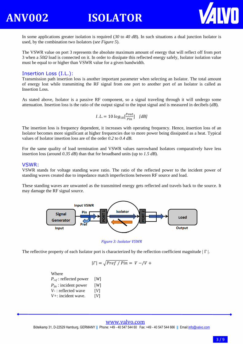
VSWR: VSWR stands for voltage standing wave ratio. The ratio of the reflected power to the incident power of
standing waves created due to impedance match imperfections between RF source and load.
These standing waves are unwanted as the transmitted energy gets reflected and travels back to the source. It
may damage the RF signal source.
Figure 3: Isolator VSWR
The reflective property of each Isolator port is characterized by the reflection coefficient magnitude | |.
| | √
Where
Pref : reflected power [W]
Pin : incident power [W]
V- : reflected wave [V]
V+: incident wave. [V]

www.valvo.com Bötelkamp 31, D-22529 Hamburg, GERMANY || Phone: +49 - 40 547 544 60 Fax: +49 - 40 547 544 666 || Email:[email protected]
4 / 9
ANV002 ISOLATOR
The resulting VSWR is given by:
| |
| |
The effective input VSWR of an Isolator will vary as a function of the load VSWR. If the output load
mismatch is increased, more energy is reflected towards the termination port. After attenuated by the isolation
it is then reflected back to the input. Due to which there is increase in total VSWR observed at the input.
Therefore, a low VSWR specification is always desirable.
VSWR is expressed in ratio form relative to 1 (example 1.25:1). Following are two special cases of VSWR:
- VSWR of ∞:1 is obtained when the load is an open circuit
- VSWR of 1:1 is obtained when the load is perfectly matched to source impedance.
Power Ratings: Power ratings are a measure of maximum RF signal power handling capacity of an Isolator, without
degradation in performance, signal distortion and /or attenuation. Exceeding these absolute ratings can cause
malfunctioning of the Isolator. Depending on the nature of applied RF signal, an Isolator can have following
different power ratings:
Average Power Ratings: The Average power represents the maximum power that the Isolator can
handle when power is applied continuously. This can be the average power of a continuous wave (CW) signal,
or the temporal average of the power of a pulsed signal. In the case of a CW signal, the average power rating
of the Isolator must be greater than the average power of the applied RF signal. Whereas for pulse signal, the
Isolator average power rating must be greater than the product of temporal peak and duty cycle of the applied
RF signal.
Peak Power Ratings: The capability of the Isolator to handle applied pulsed RF signal with certain
peak level. The temporal peak level of applied RF signal must not exceed the peak power rating of the
Isolator.
Reflective Power Ratings: The capability of the Isolator terminated port (e.g. port 3) to handle and
dissipate the reflected RF signal from output port (e.g. port 2) is known as reflective power ratings. This
power rating depends on the quality of termination which can be customized during manufacturing process. In
order to dissipate this reflected energy safely, matched termination power ratings must be equal to or higher
than the reflected power ratings.
In case when the termination receives too much power for long period, it will be damaged. If the termination
is damaged due to excessive power levels, the reflected signals will be directed back to the RF signal source
because of the circular signal flow. The power ratings of the Isolator are determined by the following primary
factors:
- Voltage levels: Voltage levels are ultimately determined by the incident and reflected signal levels and the
effective VSWR of the Isolator.
- Heat dissipation: Heat is generated in the Isolator because of insertion losses and reflections. This heat is
nothing but unwanted form of power. Hence, it should be dissipated otherwise it can cause following
adverse effects on the Isolator operation:
Degaussing of the permanent magnets that bias the ferrites.
Once the magnets are completely degaussed, the dielectric will melt which eventually destroys the
Isolator.
Thermal expansion of the internal circuit to distort geometric parameters and thereby degrading
quoted specifications.

www.valvo.com Bötelkamp 31, D-22529 Hamburg, GERMANY || Phone: +49 - 40 547 544 60 Fax: +49 - 40 547 544 666 || Email:[email protected]
5 / 9
ANV002 ISOLATOR
Heat dissipation is mainly determined by the impedance match quality and power ratings of an Isolator
termination. Hence, sometimes it is beneficial to operate the Isolator with heat sink, to handle power levels
which are closer to the maximum power levels of the Isolator.
Group Delay: The time taken by the applied RF signal to travel from input port towards the output port of the Isolator is
called as Group delay. It is typically expressed in picoseconds or nanoseconds; it indicates the phase linearity
of the Isolator.
Isolator group delay measurement is done using frequency domain method. This involves considering the
vector S-parameter data over desired frequency range for the Isolator. From this S-parameter data set group
delay is evaluated as a function of frequency.
Mathematically, it is the negative of the rate of change of phase with angular frequency.
τg = - (∂ɸ/ ∂ω)
Where,
ɸ: total phase shift [Radians]
ω: angular frequency [Radians/Seconds]
f: frequency [Hertz].
It is desirable to have a group delay value that is constant relative to all frequencies in the band of interest. A
constant group delay represents a linear phase over the desired frequency band. On the other hand large
fluctuations in group delay represent phase nonlinearities caused by the Isolator. These nonlinearities in a
transmission path of RF signal are undesirable, as they indicate the signal degradation by the Isolator.
Spin Waves: Spin waves are associated with Isolator ferrite discs and there measurement is important to determine the
power handling of ferrites. Power handling capability of Isolator in turn depends on the power threshold of
ferrites. Above the threshold power level, there is an abrupt rise in the peak power. At certain critical RF
power level, spin waves excitation starts.
Spin wave instability disrupts the RF signal driven uniform mode. The excited spine waves are out of the
phase with uniform mode and have same or harmonics frequencies of the uniform mode. These form a wave
pattern causing the saturation of the main resonance line width. As saturation level begins to increase
absorption within the ferrite increases nonlinearly.
These spin waves eventually increase heat and Isolator insertion loss than the specified values.
Applications:
Signal Source Protection: An Isolator is used to isolate microwave components from each other when working into an open or short
circuit. It isolates the unwanted reflected signals which may cause damage to the RF transmitter and other
units. As shown in the Fig. Isolator is placed in the measurement path of a RF test bench between a signal
source and the device under test (DUT).
By doing so we ensure that signal reflections caused by any mismatches will dissipate at the termination of the
isolator and not travel back into the signal source. Isolators are used for decoupling of RF signal source and
load stages thereby reducing load return loss, VSWR and intermodulation distortions.

www.valvo.com Bötelkamp 31, D-22529 Hamburg, GERMANY || Phone: +49 - 40 547 544 60 Fax: +49 - 40 547 544 666 || Email:[email protected]
6 / 9
ANV002 ISOLATOR
Figure 4: Signal Source Protection
High Isolation: For applications where higher isolation and much better directivity are needed, a dual junction Isolator is used.
A dual junction Isolator is series combination two Isolators integrated in a single package.
Figure 5: Dual Isolator
As shown in Figure 5 a constructed dual Isolator has four ports with following status:
- Port 1: Input
- Port 2: Output
- Port 3: Terminated
- Port 4: Terminated
Applied RF signal is forced to flow from port 1 to port 2; while ports 3 and 4 are internally terminated with
matched loads. When travelling from port 1 to port 2 transmitted signal cross two ferrite junctions. In this way
very high isolation is achieved between the input and output. Typical isolation obtained with a dual Isolator is
in the range of 40 to 50 dB.
RF Link Combiner: Apart from its typical applications an Isolator can be used as a RF signal combiner for multiple transmitters in
the VHF/UHF bands.
As shown in the Figure 6, the transmitter is connected to a cavity, which is tuned to its signal, via an Isolator.
Depending on coupling of the cavity cable lengths of λ/4 or odd multiples of it or λ/2 or multiples of it,
connect the different cavities with a star point, which leads to the antenna.
The transmitter signal travels to the star point through the Isolator 1 and the cavity 1. The other transmitters
have different operating frequencies, therefore the cavities are tuned to different frequencies too, and the

www.valvo.com Bötelkamp 31, D-22529 Hamburg, GERMANY || Phone: +49 - 40 547 544 60 Fax: +49 - 40 547 544 666 || Email:[email protected]
7 / 9
ANV002 ISOLATOR
cables transform their impedances to high impedance at the star point. This allows the signal of the transmitter
TX1 travel to the antenna, attenuated about 1.5 dB by cavity 1 and losses in the cables and the other cavities.
The losses in the other cavities depend upon the frequency spacing, the coupling and the Q-factors of the
cavities. The major advantage of this configuration is that, the total loss of the signal in the combining
network does not increase significantly with increase in the number of transmitters. For the 4 transmitters the
combining loss is typically 2 dB which is much less than the combining loss of 7dB using the conventional
3dB Hybrids. In this manner the combining network of up to 18 transmitters can be formed in the UHF-band.
Figure 6: Radio Link Combiner
Using the above principle RF amplifier stage combiner and radio link combiner networks can be designed
using Isolators.
RF Decoupling: When transmitter / receiver is directly connected to an antenna it may be influenced by antenna impedance
changes. These impedance variations are caused due to snow or near-by obstacles, can introduce the
intermodulation products .This can be avoided by an Isolator connected between antenna transmitter/receiver.
The same principle can be used to achieve fine tuning, reduce coupling and avoid overloading between two or
more amplifier stages.
Application Areas: Isolators are an important device for any industry that utilizes radio frequency or microwave signals for
communication. Following are some industrial fields served by Isolators:
- Television & Radio broadcasting
- Radio links & telecommunication networks
- Aviation & navigation industries
- Military equipment & Radar systems
- Laboratory measurement systems
- Industrial microwave heating
www.valvo.com Bötelkamp 31, D-22529 Hamburg, GERMANY || Phone: +49 - 40 547 544 60 Fax: +49 - 40 547 544 666 || Email:[email protected]
8 / 9
ANV002 ISOLATOR
Operating Precautions: Like other high frequency components Isolators have some kind of operating safety and handling precautions.
In this section the Isolator protection measures have been considered.
Operating Temperature: The material properties of ferrites and magnets used in Isolators are temperature dependent. This can cause
unstable performance characteristics over operating range. This mainly depends on the magnetic field, applied
to saturate the ferrite material. Following techniques can extend the Isolator temperature performance range
by a significant amount.
- Temperature compensated magnets and ferrites materials need to be used where wide temperature ranges
are required.
- For proper thermal behavior Isolator is installed such that ambient temperature air must be allowed to
circulate freely.
- External heat sinks and forced air cooling systems must be used under high heat dissipations and high
ambient temperatures.
External Magnetic Fields: Isolators have permanently biased magnets that produce strong fields to control RF signal flow. When an
Isolator is placed in close proximity to another magnet/magnetic fields the two magnetic fields interact with
each other.
Isolators are normally semi-shielded for operation in close proximity of large ferrous objects or external
magnetic fields to minimize magnetic interference.
Even if the Isolator is magnetically shielded, strong AC field can affect its characteristics and even
demagnetize the internal magnets, causing complete de-tuning. This mechanism is known as degaussing. At
this stage the Isolator magnets are unable to control the RF signal flow. Hence, during storage it is
recommended that Isolators should be separated by at least 3 inches from other magnetic devices.
On Site Mounting: To ensure the satisfactory performance and avoid any mechanical damage to the Isolator following measures
should be taken into account:
- With a proper assembly mount an Isolator in its specified operating conditions only
- Do not put too much stress on Isolator connectors
- If possible avoid mounting an Isolator near strong AC fields, magnetic fields and high power sources
Packaging Types: Depending on the application environment requirements various connector types can be supplied on Isolators
such as:
- Drop-In Isolators
- N-Type Isolators
- SMA Coaxial Isolators
- Surface Mount Isolators
Some connectors however, cause limitations in the electrical performance of the high frequency and broad
bandwidth Isolators. The package size may have to be increased to accommodate certain connector types. In
general SMA male or female connectors are the most popular and easiest to install. Many times N-Type and
right angle connectors of various types are used. Some connectors, however, cause limitations in the electrical
performance of the high frequency and broad bandwidth Isolators.

www.valvo.com Bötelkamp 31, D-22529 Hamburg, GERMANY || Phone: +49 - 40 547 544 60 Fax: +49 - 40 547 544 666 || Email:[email protected]
9 / 9
ANV002 ISOLATOR
Another connector configuration can be obtained by mounting the Isolator on a waveguide adapter. These
devices are known as Isoadaptors. In such devices the large waveguide section provides a rigid base for the
usually smaller coaxial circulator. These units are particularly useful when both waveguide and coaxial
connectors are required. For example, the waveguide port can accept a signal directly from a waveguide
antenna, while the output from a SMA connector port can be fed directly to solid-state amplifier.
Isolators can also be supplied with removable connectors. The connector shell can be removed to allow the
center conductor to be directly soldered to a circuit board. Normally a high temperature solder is used for the
internal solder joint so the pin will not move while being soldered to the board. This type of component is
known as drop in Isolator.

ABOUT VALVO Valvo Bauelemente GmbH is a Germany based company specializing in design and
developments of standard as well as special RF and microwave ferrite components. Valvo Bauelemente GmbH has more than 30 years of experience in providing well-
rounded expertise solutions, technologies and design techniques.
The core of the company is a highly experienced team of respected technologists with
developments of performance specific, high reliability complex products. The
company has delivered excellent performance in several International R&D projects.
All products are controlled to the highest standards for guaranteed delivery and
customer satisfaction.
PRODUCTS
Valvo Bauelemente GmbH is focused on 50 MHz to 18 GHz Circulators, Isolators,
Waveguides, and microwave ferrite devices. We offer narrow and broad band devices
in coaxial, waveguide, drop-in constructions which are ideally suited for integration
into compact systems.
Our highly skilled staff has a strong working knowledge and experience on a variety
of ferrite devices with over 2,000 existing designs. This makes us possible to offer
custom product solutions in addition to wide range standard product solutions.
For more information regarding products, technical data please visit www.valvo.com
or please contact our sales department on [email protected] for any specific
requirements.
Copyright © Valvo Bauelemente GmbH 1999
All rights are reserved. Reproduction in whole or in part is prohibited without the prior written consent of the copyright owner. The information presented in this document does not form part of any quotation or contract, is believed to be accurate and reliable and may be changed without notice. No liability will be accepted by the publisher for any consequence of its use. Publication thereof does not convey nor imply any license under patent- or other industrial or intellectual property rights.


![[XLS]Final Results-xlsdload.osb.s3.amazonaws.com/results/cambridge18final... · Web view9610 544 4011 43 545 3094 51 546 8724 5 547 6310 93 548 8597 94 549 6116 6 550 5382 95 551](https://static.documents.pub/doc/80x56/5b1d48c27f8b9acc488b461a/xlsfinal-results-web-view9610-544-4011-43-545-3094-51-546-8724-5-547-6310.jpg)
![Photochemical Functionalization of Helicenes...Functionalization of bromo[6]helicenes. Chem. Eur.J.2020, 26,543–547 544 T 2020 The Authors. Published by Wiley-VCH Verlag GmbH&Co.](https://static.documents.pub/doc/80x56/60cb0fd9ceb76352750066f7/photochemical-functionalization-of-helicenes-functionalization-of-bromo6helicenes.jpg)


