Moteurs diesels - Agent AUS 32 de réduction des NOx - Partie 4: Interface de remplissage
Reference language version: English French Russian
Introductory note
This new working draft has been prepared by WG14 considering the comments received by SC5. These comments were eaxmined by the SC5 ad hoc group "urea refilling inteface" in charge of this subject.
As agreed, the CD ballot is a 2 months enquiry only.
THIS DOCUMENT IS STILL UNDER STUDY AND SUBJECT TO CHANGE. IT SHOULD NOT BE USED FOR REFERENCE PURPOSES.
FORM 7 (ISO) Version/V97.1.2
Document type: International Standard Document subtype: Document stage: (30) Committee Document language: E H:\Abteilungs Archiv\Geschichtsakte FAKRA-Normen\Normen_20001-40000\22241\Part 4\ISO_22241_4_30Dec05(E).doc STD Version 2.2
ISO TC 22/SC 5 Date: 2005-12-30
ISO/CD 22241-4
ISO TC 22/SC 5/WG
Secretariat: AFNOR/BNA
Diesel engines — NOx reduction agent AUS 32 — Part 4: Refilling interface
Moteurs diesels — Agent AUS 32 de réduction des NOx — Partie 4: Interface de remplissage
Warning
This document is not an ISO International Standard. It is distributed for review and comment. It is subject to change without notice and may not be referred to as an International Standard.
Recipients of this draft are invited to submit, with their comments, notification of any relevant patent rights of which they are aware and to provide supporting documentation.
This ISO document is a working draft or committee draft and is copyright-protected by ISO. While the repro-duction of working drafts or committee drafts in any form for use by participants in the ISO standards devel-opment process is permitted without prior permission from ISO, neither this document nor any extract from it may be reproduced, stored or transmitted in any form for any other purpose without prior written permission from ISO.
Requests for permission to reproduce this document for the purpose of selling it should be addressed as shown below or to ISO's member body in the country of the requester:
[Indicate the full address, telephone number, fax number, telex number, and electronic mail address, as ap-propriate, of the Copyright Manager of the ISO member body responsible for the secretariat of the TC or SC within the framework of which the working document has been prepared.]
Reproduction for sales purposes may be subject to royalty payments or a licensing agreement.
ISO (the International Organization for Standardization) is a worldwide federation of national standards bodies (ISO member bodies). The work of preparing International Standards is normally carried out through ISO tech-nical committees. Each member body interested in a subject for which a technical committee has been estab-lished has the right to be represented on that committee. International organizations, governmental and non-governmental, in liaison with ISO, also take part in the work. ISO collaborates closely with the International Elec-trotechnical Commission (IEC) on all matters of electrotechnical standardization.
International Standards are drafted in accordance with the rules given in the ISO/IEC Directives, Part 2.
The main task of technical committees is to prepare International Standards. Draft International Standards adopted by the technical committees are circulated to the member bodies for voting. Publication as an Interna-tional Standard requires approval by at least 75 % of the member bodies casting a vote.
Attention is drawn to the possibility that some of the elements of this document may be the subject of patent rights. ISO shall not be held responsible for identifying any or all such patent rights.
ISO 22241-4 was prepared by Technical Committee ISO/TC 22, Road vehicles, Subcommittee SC 5, Engine tests.
ISO 22241 consists of the following parts, under the general title Diesel engines — NOx reduction agent AUS 32:
Diesel engines — NOx reduction agent AUS 32 — Part 4: Refilling interface
1 Scope
This International Standard specifies the refilling interface for the NOX reduction agent AUS 32 in compliance with ISO 22241-1, which is needed to operate converters with Selective Catalytic Reduction (SCR) exhaust treatment system. The Standard specifies the minimum functional and geometric requirements of an open refilling system, in order to ensure compatibility between the filler neck on the vehicles and the filler nozzle on pumps at filling stations. Compatibility conditions for a sealed refilling system are provided in Annex A.
This International Standard applies to road vehicles using the SCR technology.
NOTE In the remaining parts of this Standard, the term "NOx reduction agent AUS 32" will be abbreviated to "AUS 32".
2 Normative references
The following referenced documents are indispensable for the application of this document. For dated refer-ences, only the edition cited applies. For undated references, the latest edition of the referenced document (including any amendments) applies.
ISO 22241-1 Diesel engines – NOx reduction agent AUS 32 – Part 1: Quality requirements
ISO 22241-3 Diesel engines – NOx reduction agent AUS 32 – Part 3: Handling, transportation, storage 1)
EN 13012 Petrol filling stations - Construction and performance of automatic nozzles for use on fuel dispensers
1) in preparation
3 Terms and definitions
For the purposes of this document, the following terms and definitions apply.
3.1 open refilling system dispensing equipment where the interface between the refilling system and the filler neck of the AUS 32 on-board tank is not gas-tight
3.2 sealed refilling system dispensing equipment where the interface between the refilling system and the filler neck of the AUS 32 on-board tank is gas-tight
3.3 AUS 32 on-board tank fluid reservoir for AUS 32, mounted on the vehicle
3.4 filler neck part of the AUS 32 on-board tank where the opening is formed to allow the tank to be refilled
3.5 inlet adapter device which fits inside the filler neck on the AUS 32 on-board tank and which incorporates the interface detail of the refilling system
3.6 filler cap device fitted to the filler neck to cover the opening when not in use and prevent spillage from the AUS 32 on-board tank
3.7 filler nozzle device connected to the refilling system which allows the operator to control the flow of AUS 32 during the fill-ing and which consists of a nozzle spout and an automatic shut-off system
4 Requirements
4.1 Functional requirements
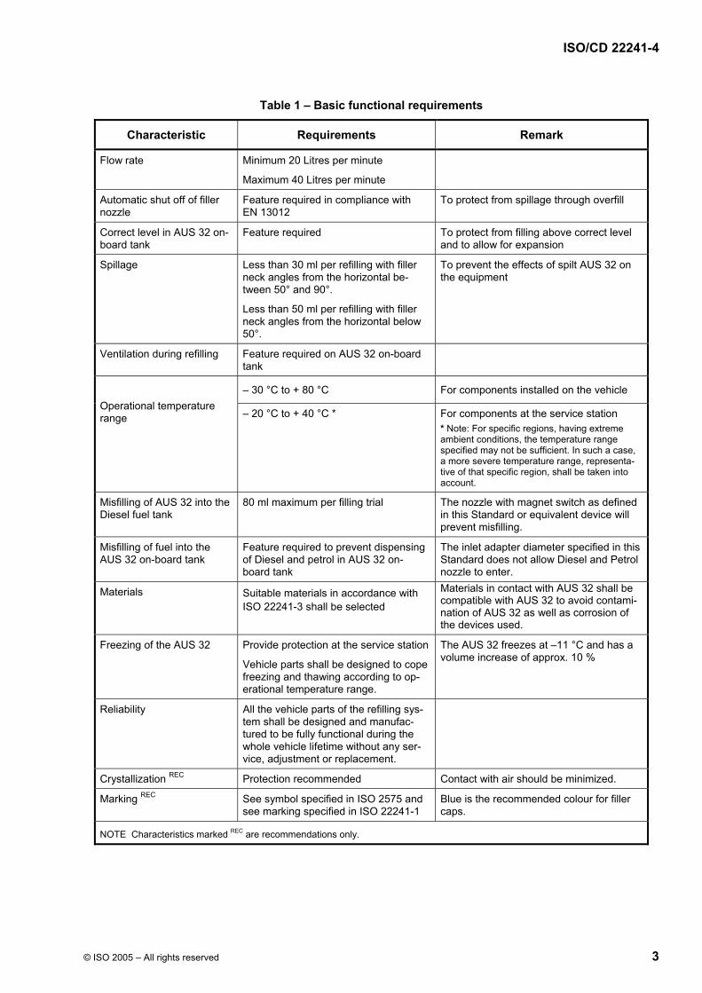
The AUS 32 on-board tank, the filler neck, inlet adapter and the refilling system shall comply with the basic functional requirements specified in Table 1.
Feature required To protect from filling above correct level and to allow for expansion
Spillage Less than 30 ml per refilling with filler neck angles from the horizontal be-tween 50° and 90°.
Less than 50 ml per refilling with filler neck angles from the horizontal below 50°.
To prevent the effects of spilt AUS 32 on the equipment
Ventilation during refilling Feature required on AUS 32 on-board tank
– 30 °C to + 80 °C For components installed on the vehicle
Operational temperature range – 20 °C to + 40 °C *
For components at the service station * Note: For specific regions, having extreme ambient conditions, the temperature range specified may not be sufficient. In such a case, a more severe temperature range, representa-tive of that specific region, shall be taken into account.
Misfilling of AUS 32 into the Diesel fuel tank
80 ml maximum per filling trial
The nozzle with magnet switch as defined in this Standard or equivalent device will prevent misfilling.
Misfilling of fuel into the AUS 32 on-board tank
Feature required to prevent dispensing of Diesel and petrol in AUS 32 on-board tank
The inlet adapter diameter specified in this Standard does not allow Diesel and Petrol nozzle to enter.
Materials Suitable materials in accordance with ISO 22241-3 shall be selected
Materials in contact with AUS 32 shall be compatible with AUS 32 to avoid contami-nation of AUS 32 as well as corrosion of the devices used.
Freezing of the AUS 32 Provide protection at the service station
Vehicle parts shall be designed to cope freezing and thawing according to op-erational temperature range.
The AUS 32 freezes at –11 °C and has a volume increase of approx. 10 %
Reliability All the vehicle parts of the refilling sys-tem shall be designed and manufac-tured to be fully functional during the whole vehicle lifetime without any ser-vice, adjustment or replacement.
Crystallization REC Protection recommended Contact with air should be minimized.
Marking REC See symbol specified in ISO 2575 and see marking specified in ISO 22241-1
Blue is the recommended colour for filler caps.
NOTE Characteristics marked REC are recommendations only.
The filler neck allows the vehicle manufacturers or any authorized person to install or remove an inlet adapter which can accommodate an open refilling system or a sealed refilling system. For dimensional details see Figure 1 and Table 2.
The geometric location and orientation of the filler neck on the vehicle will be specified by the vehicle manu-facturer, taking into account the free space required for the proper application of the nozzle, see 4.6.
Figure 1 – Filler neck
Table 2 – Dimensions of the filler neck
Dimensions in millimetres
Characteristic Code Dimensions
Diameter inlet or upper stop Ø A ≥ 39,5
Diameter upper support Ø B ≥ 37
Height upper stop C ≤ 48
D ≥ 30° b Filler neck angle from horizontal a
E ≤ 90°
a recommended is an angle between 50° - 90° b if, due to body design restrictions, an angle smaller than 30° is chosen by the de-
signer, spillage may be larger than specified in Table 1 and the function of the nozzle may be limited
The inlet adapter shall be designed to fit inside the filler neck. The internal diameter of the inlet adapter shall prevent a refilling nozzle spout greater than 19,5 mm diameter from entering the inlet adapter.
The inlet adapter shall be equipped with a magnet ring having the characteristics specified in Figure 2 and Table 3.
Dimensions in millimetres
Figure 2 – Inlet adapter
Table 3 – Magnet ring characteristics
Parameter Requirements
Dimensions Ø 34 mm x Ø 24 mm x 10 mm
(outer diameter x inner diameter x height)
Material Neodymium-Iron-Bor (NdFeB)
Magnet parameter Remanence: 1,2 to 1,3 Tesla
Coercivity: 800 to 900 kA/m
Orientation North pole pointing outwards from the tank
Marking and colouring of the filler cap should be as recommended in Table 1.
4.5 Filler nozzle
The nozzle spout shall be cylindrical with a diameter 19 mm ± 0,25 mm and a length of 70 mm ± 2 mm, see Figure 3.
The nozzle spout shall be equipped with a magnet switch which interacts with the magnetic ring of the inlet adapter. If the nozzle is inserted accidentally into a fuel tank or another liquid container, the magnet switch prevents misfilling.
Dimensions in millimetres
Figure 3 – Nozzle spout Figure 4 – Position of nozzle spout with magnet switch inserted into inlet adapter
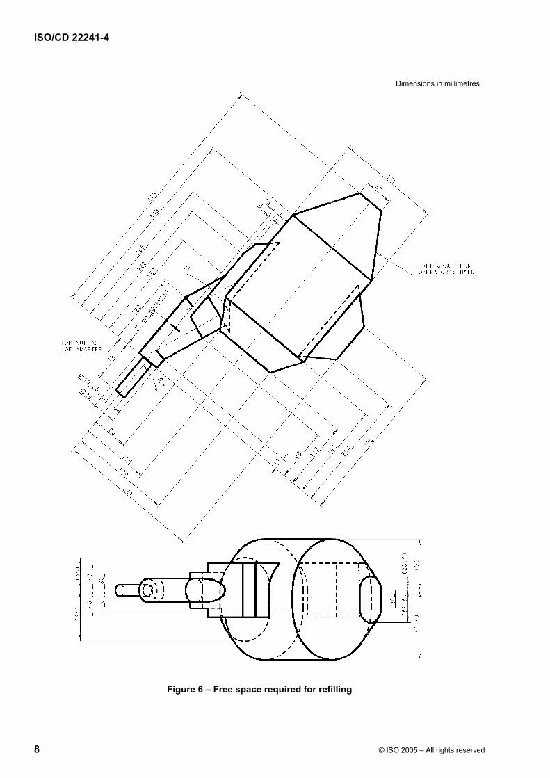
Vehicle and body manufacturers shall ensure that the space defined in Figures 5 and 6 is available and not obstructed by any components in order to permit unrestricted access to the AUS 32 on-board tank for inser-tion of the nozzle spout into the tank for refilling and for the subsequent removal from tank. The dimensions specified in Figure 6 take into account the following parameters:
⎯ different nozzle designs;
⎯ space required for manual insertion and removal of the nozzle (72 mm movement);
⎯ space required for the hand of the operator.
Figure 5 – 3 D view of free space required for refilling
Compatibility conditions for sealed refilling systems
A.1 Functional conditions
The sealed refilling system shall comply with the basic functional requirements specified in Table 1, except that the maximum spillage rate shall not be more than 20 ml. Misfilling of AUS 32 into the Diesel tank is not possible by the use of a sealed system. Misfilling of Diesel fuel into the AUS 32 on-board tank is not possible either. Emergency refilling (e.g. by canister) shall be possible; see for example Figure A.3.
A.2 Filler neck
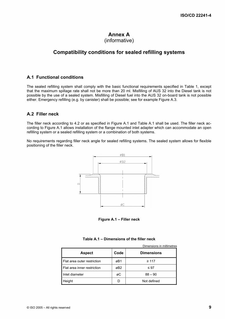
The filler neck according to 4.2 or as specified in Figure A.1 and Table A.1 shall be used. The filler neck ac-cording to Figure A.1 allows installation of the flange mounted inlet adapter which can accommodate an open refilling system or a sealed refilling system or a combination of both systems.
No requirements regarding filler neck angle for sealed refilling systems. The sealed system allows for flexible positioning of the filler neck.
The inlet adapter shall be designed to fit inside the filler neck. The inlet adapter shall include the sealed filling system coupling. The sealed system coupling shall have an external diameter of 19,25 mm.
A.4 Filler caps
Needed for dust protection only.
A.5 Filler nozzle
The nozzle must be compatible with the sealed system inlet adapter.
If the nozzle is inserted into a tank different from the AUS 32 on-board tank, it shall not be possible to dispend AUS 32 in that tank.
A.6 Minimum free space for the nozzle
The nozzle of the sealed system including the operator's hand and the space needed for insertion and re-moval shall be in compliance with 4.6.