96
ISP Network Design Scalable Network Design 1
| Date post: | 22-Dec-2015 |
| Category: |
Documents |
| Upload: | kathleen-francis |
| View: | 235 times |
| Download: | 1 times |

ISP Network Design
Scalable Network Design
1

ISP Network Design
• PoP Topologies and Design• Backbone Design• Addressing• Routing Protocols• Security• Out of Band Management• Operational Considerations
2

Point of Presence Topologies
3
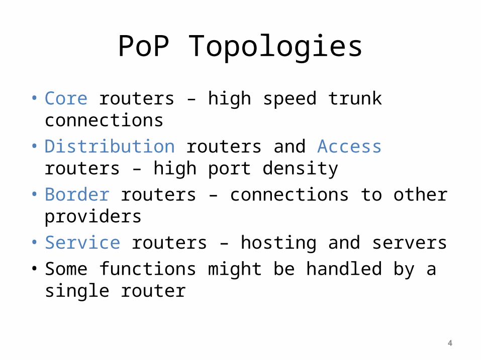
PoP Topologies
• Core routers – high speed trunk connections• Distribution routers and Access routers – high
port density• Border routers – connections to other
providers• Service routers – hosting and servers• Some functions might be handled by a single
router
4

PoP Design
• Modular Design• Aggregation Services separated according to– connection speed– customer service– contention ratio– security considerations
5
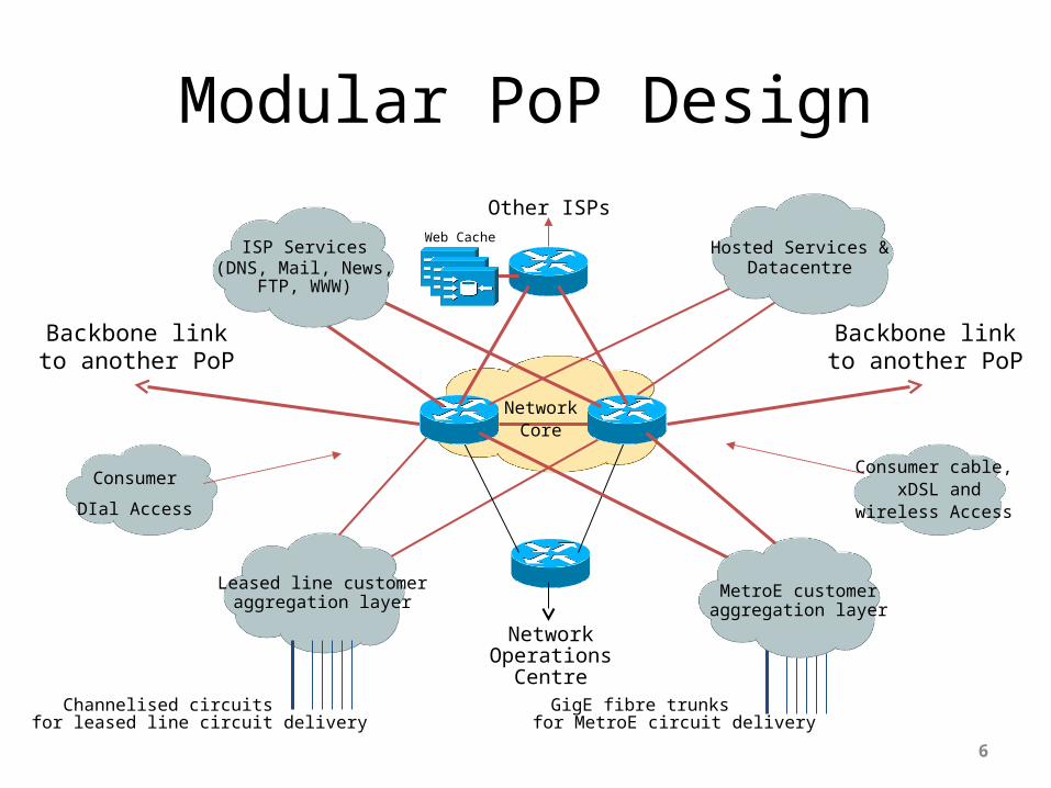
Modular PoP Design
6
Backbone linkto another PoP
Backbone linkto another PoP
Leased line customeraggregation layer
for leased line circuit deliveryChannelised circuits
NetworkOperations
Centre
Consumer
DIal Access
NetworkCore
Consumer cable, xDSL and
wireless Access
for MetroE circuit deliveryGigE fibre trunks
MetroE customeraggregation layer
ISP Services(DNS, Mail, News,
FTP, WWW)
Hosted Services & Datacentre
Other ISPsWeb Cache

Modular Routing Protocol DesignSmaller ISPs
• Modular IGP implementation– IGP “area” per PoP– Core routers in backbone area (Area 0/L2)– Aggregation/summarisation where possible into the
core• Modular iBGP implementation– BGP route reflector cluster per module– Core routers are the route-reflectors– Remaining routers are clients & peer with route-
reflectors only
7
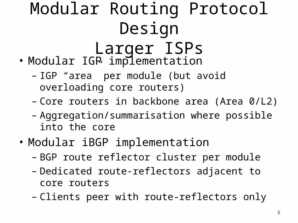
Modular Routing Protocol DesignLarger ISPs
• Modular IGP implementation– IGP “area” per module (but avoid overloading core
routers)– Core routers in backbone area (Area 0/L2)– Aggregation/summarisation where possible into the
core
• Modular iBGP implementation– BGP route reflector cluster per module– Dedicated route-reflectors adjacent to core routers– Clients peer with route-reflectors only
8

Point of Presence Design
9
PoP Modules
• Low Speed customer connections– PSTN/ISDN dialup– Low bandwidth needs– Low revenue, large numbers
• Leased line customer connections– E1/T1 speed range– Delivery over channelised media– Medium bandwidth needs– Medium revenue, medium numbers
10
PoP Modules
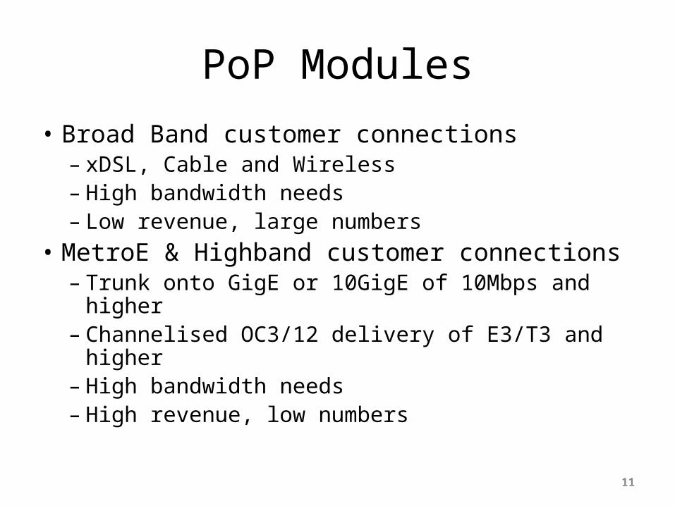
• Broad Band customer connections– xDSL, Cable and Wireless– High bandwidth needs– Low revenue, large numbers
• MetroE & Highband customer connections– Trunk onto GigE or 10GigE of 10Mbps and higher– Channelised OC3/12 delivery of E3/T3 and higher– High bandwidth needs– High revenue, low numbers
11
PoP Modules
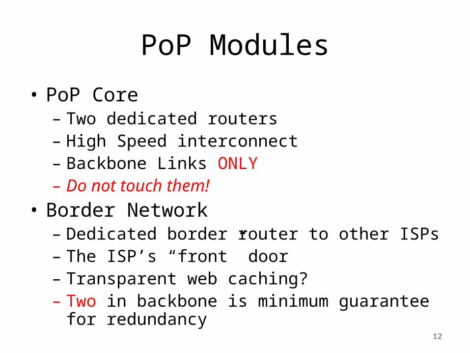
• PoP Core– Two dedicated routers– High Speed interconnect– Backbone Links ONLY– Do not touch them!
• Border Network– Dedicated border router to other ISPs– The ISP’s “front” door– Transparent web caching?– Two in backbone is minimum guarantee for
redundancy12
PoP Modules
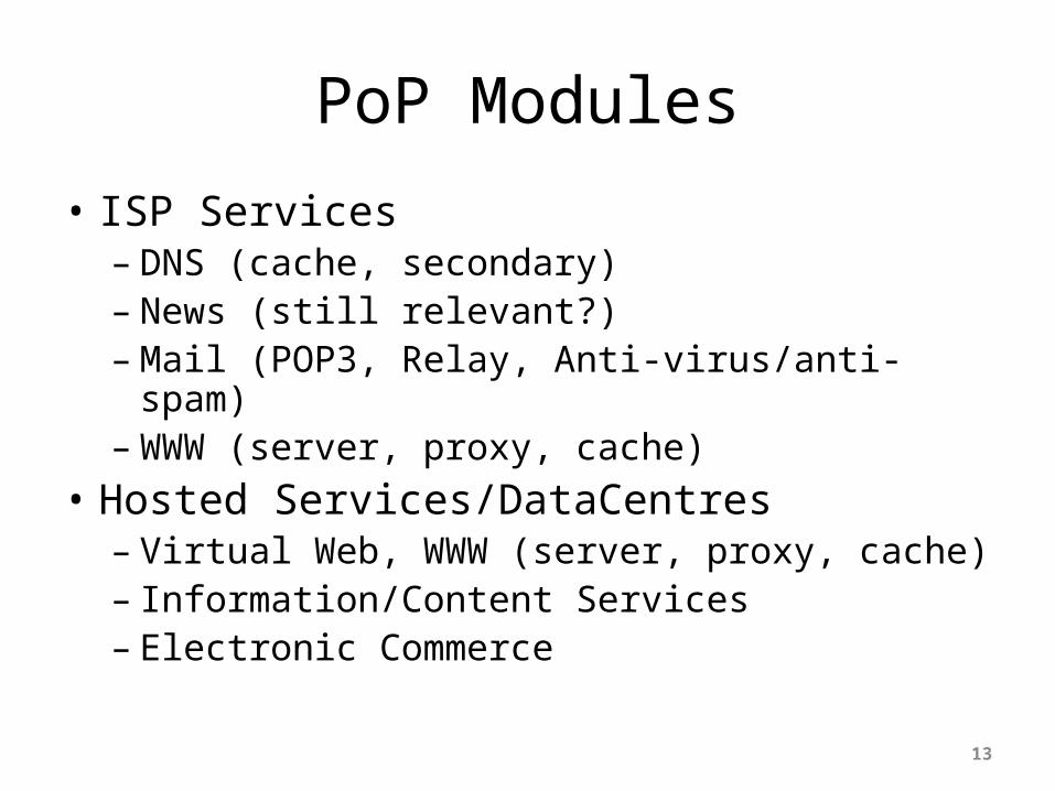
• ISP Services– DNS (cache, secondary)– News (still relevant?) – Mail (POP3, Relay, Anti-virus/anti-spam)– WWW (server, proxy, cache)
• Hosted Services/DataCentres– Virtual Web, WWW (server, proxy, cache)– Information/Content Services– Electronic Commerce
13

PoP Modules
• Network Operations Centre– Consider primary and backup locations– Network monitoring– Statistics and log gathering– Direct but secure access
• Out of Band Management Network– The ISP Network “Safety Belt”
14
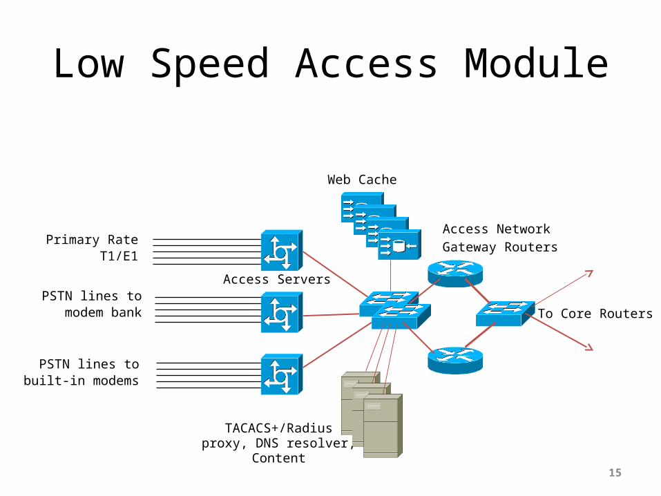
Low Speed Access Module
15
To Core Routers
Primary RateT1/E1
PSTN lines tomodem bank
PSTN lines tobuilt-in modems
Access Servers
TACACS+/Radiusproxy, DNS resolver,
Content
Web Cache
Access NetworkGateway Routers

Medium Speed Access Module
16
To Core Routers
Channelised T1/E1
64K and nx64Kcircuits
Mixture of channelisedT1/E1, 56/64K and
nx64K circuits
Aggregation Edge

High Speed Access Module
17
To Core Routers
Metro Ethernet
Channelised T3/E3
Channelised OC3/OC12
Aggregation Edge

Broadband Access Module
18
To Core Routers
Telephone Network
The cable system
BRAS
SSG, DHCP, TACACS+or Radius Servers/Proxies,
DNS resolver, Content
Web Cache
Access NetworkGateway Routers
Cable RAS
DSLAM
IP, ATM
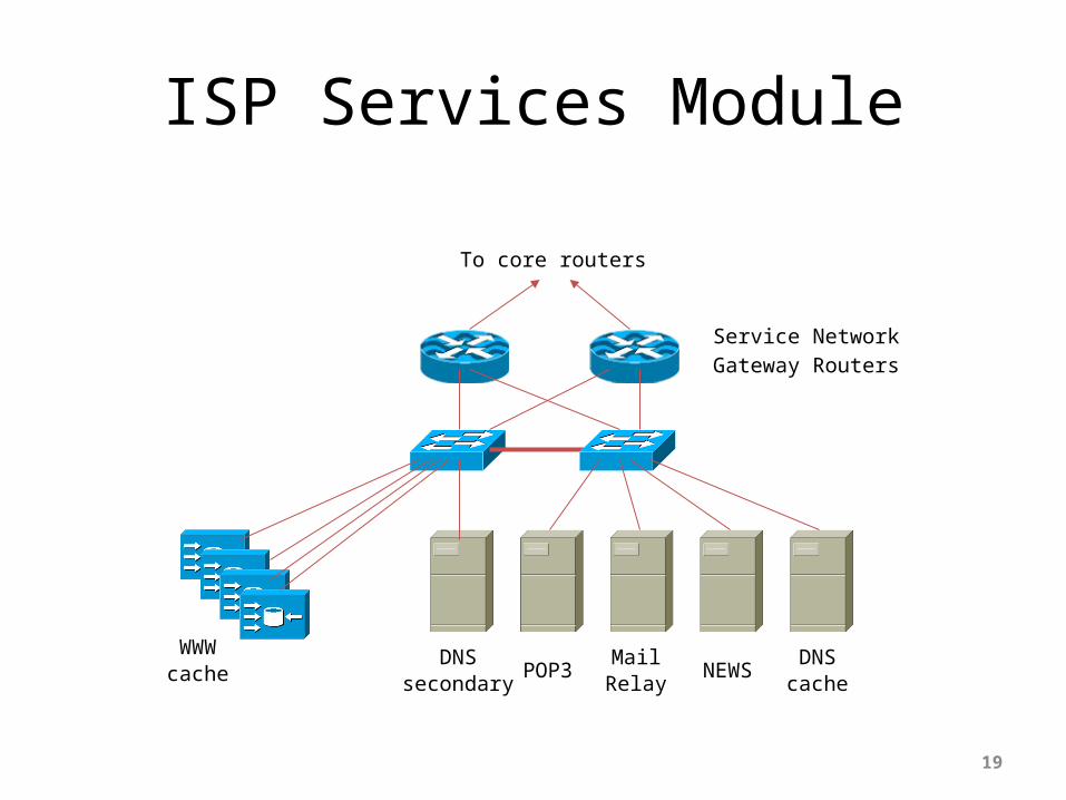
ISP Services Module
19
DNScache
DNSsecondary
POP3Mail
RelayNEWS
To core routers
WWWcache
Service NetworkGateway Routers
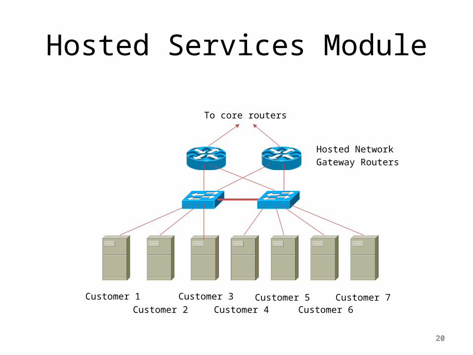
Hosted Services Module
20
Customer 7Customer 3Customer 4
Customer 5Customer 6
To core routers
Hosted NetworkGateway Routers
Customer 2Customer 1

Border Module
21
To core routers
NetworkBorder Routers
To local IXPNB: router has no default route +
local AS routing table only
ISP1 ISP2
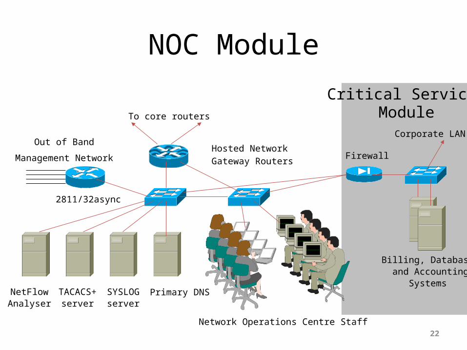
NOC Module
22
Primary DNS
To core routers
Hosted NetworkGateway Routers
SYSLOGserver
TACACS+server
Network Operations Centre Staff
Out of Band
Management Network
2811/32async
NetFlowAnalyser
Firewall
Billing, Database and Accounting
Systems
Corporate LAN
Critical ServicesModule

Out of Band Network
23
Out of Band
Management Network
Terminal serverTo the NOC
Out of Band Ethernet
NetFlow
Collector
NetFlow
enabled
routers
Routerconsoles

Backbone Network Design
24
Backbone Design
• Routed Backbone• Switched Backbone– Virtually obsolete
• Point-to-point circuits– nx64K, T1/E1, T3/E3, OC3, OC12, GigE, OC48,
10GigE, OC192, OC768• ATM/Frame Relay service from telco– T3, OC3, OC12,… delivery– Easily upgradeable bandwidth (CIR)– Almost vanished in availability now
25

Distributed Network Design
• PoP design “standardised”– operational scalability and simplicity
• ISP essential services distributed around backbone
• NOC and “backup” NOC• Redundant backbone links
26

Distributed Network Design
27
POP One
POP Two
POP Three
Customerconnections
Customerconnections
Customerconnections
Externalconnections
Externalconnections Operations Centre
BackupOperations Centre
ISP Services
ISP Services
ISP Services
Backbone Links
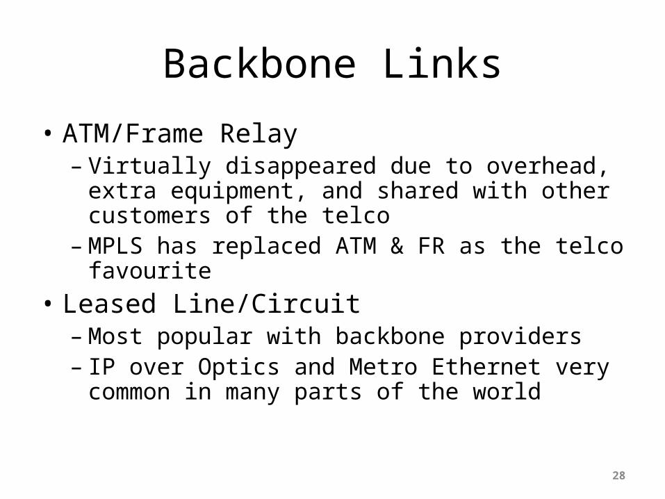
• ATM/Frame Relay– Virtually disappeared due to overhead, extra
equipment, and shared with other customers of the telco
– MPLS has replaced ATM & FR as the telco favourite
• Leased Line/Circuit– Most popular with backbone providers– IP over Optics and Metro Ethernet very common
in many parts of the world
28
Long Distance Backbone Links
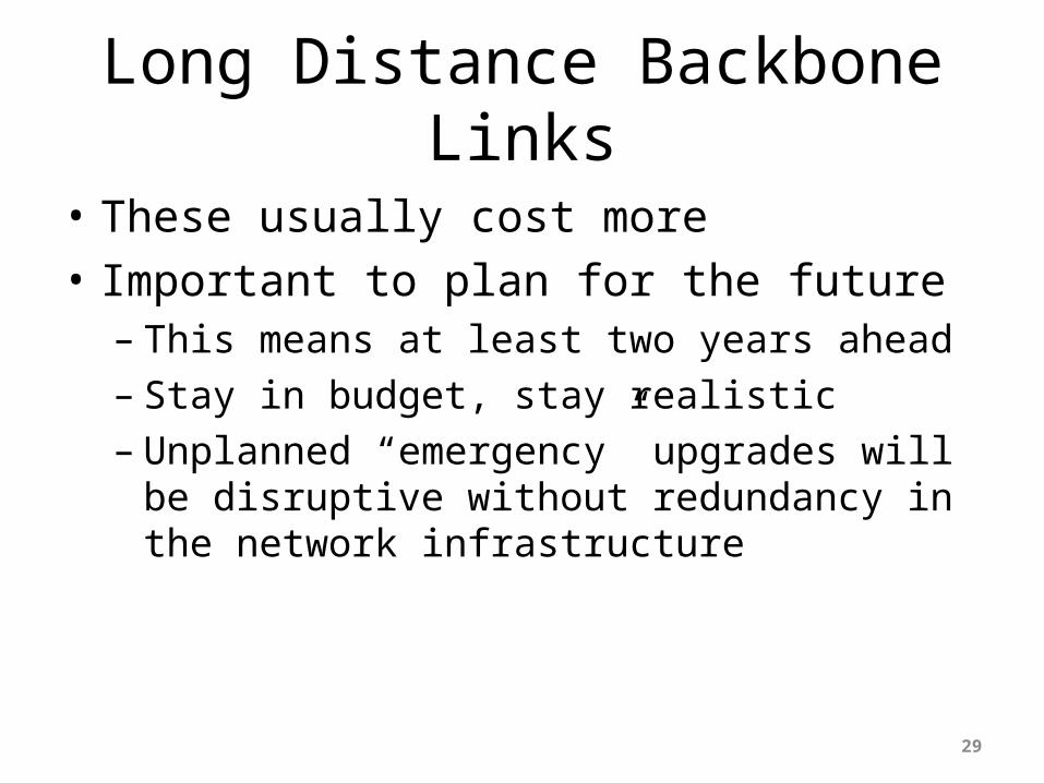
• These usually cost more• Important to plan for the future– This means at least two years ahead– Stay in budget, stay realistic– Unplanned “emergency” upgrades will be
disruptive without redundancy in the network infrastructure
29

Long Distance Backbone Links
• Allow sufficient capacity on alternative paths for failure situations– Sufficient can depend on the business strategy– Sufficient can be as little as 20%– Sufficient is usually over 50% as this offers
“business continuity” for customers in the case of link failure
– Some businesses choose 0%• Very short sighted, meaning they have no spare
capacity at all!!
30

Long Distance Links
31
POP One
POP Two
POP Three
Long distance link
Alternative/Backup Path
Metropolitan Area Backbone Links
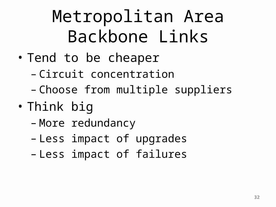
• Tend to be cheaper– Circuit concentration– Choose from multiple suppliers
• Think big– More redundancy– Less impact of upgrades– Less impact of failures
32
Metropolitan Area Backbone Links
33
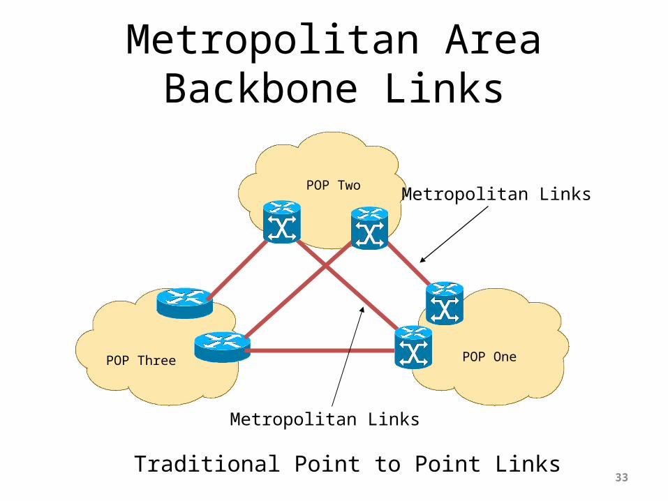
POP One
POP Two
POP Three
Metropolitan Links
Metropolitan Links
Traditional Point to Point Links

Upstream Connectivity and Peering
34
Transits
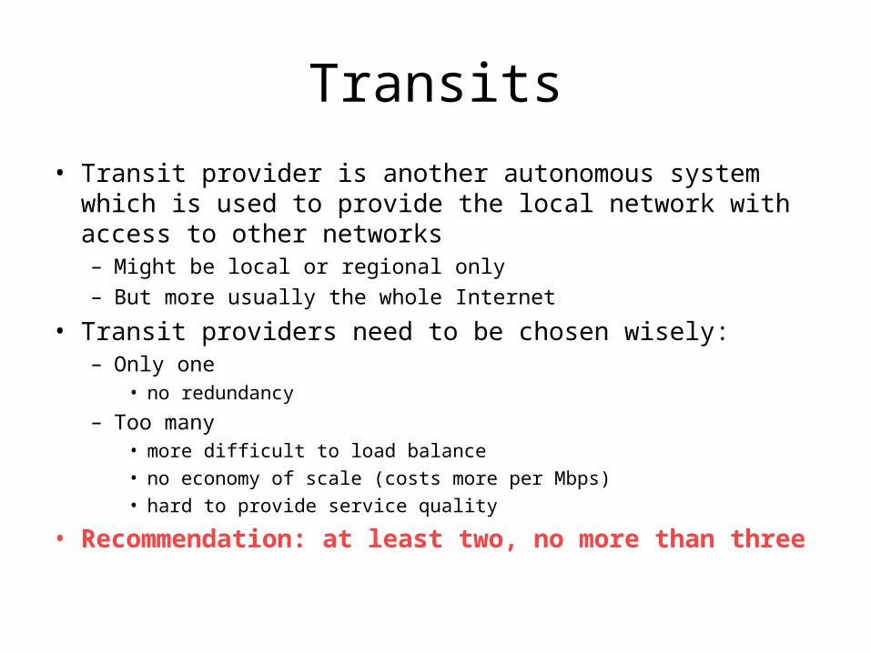
• Transit provider is another autonomous system which is used to provide the local network with access to other networks– Might be local or regional only– But more usually the whole Internet
• Transit providers need to be chosen wisely:– Only one
• no redundancy
– Too many• more difficult to load balance• no economy of scale (costs more per Mbps)• hard to provide service quality
• Recommendation: at least two, no more than three

Common Mistakes
• ISPs sign up with too many transit providers– Lots of small circuits (cost more per Mbps than larger ones)– Transit rates per Mbps reduce with increasing transit bandwidth
purchased– Hard to implement reliable traffic engineering that doesn’t need daily
fine tuning depending on customer activities
• No diversity– Chosen transit providers all reached over same satellite or same
submarine cable– Chosen transit providers have poor onward transit and peering

Peers
• A peer is another autonomous system with which the local network has agreed to exchange locally sourced routes and traffic
• Private peer– Private link between two providers for the purpose of interconnecting
• Public peer– Internet Exchange Point, where providers meet and freely decide who
they will interconnect with
• Recommendation: peer as much as possible!
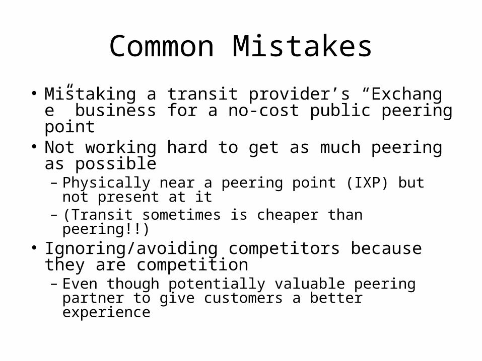
Common Mistakes• Mistaking a transit provider’s “Exchange”
business for a no-cost public peering point• Not working hard to get as much peering as
possible– Physically near a peering point (IXP) but not present
at it– (Transit sometimes is cheaper than peering!!)
• Ignoring/avoiding competitors because they are competition– Even though potentially valuable peering partner to
give customers a better experience
Private Interconnection
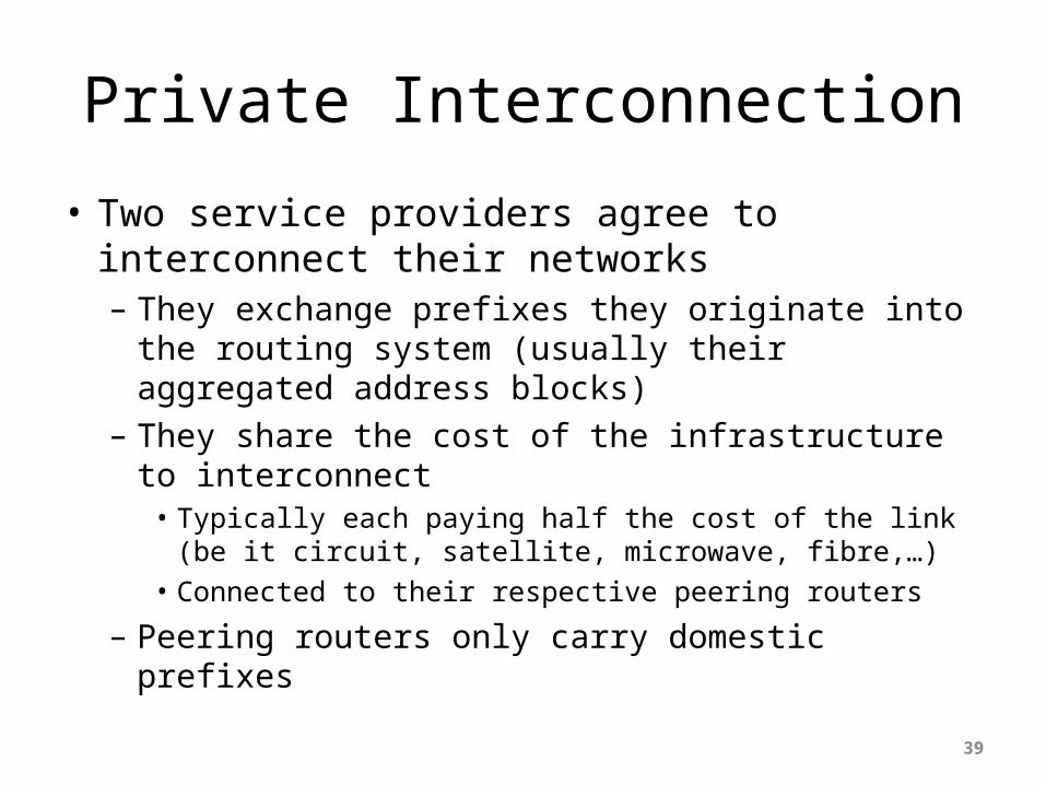
• Two service providers agree to interconnect their networks– They exchange prefixes they originate into the routing
system (usually their aggregated address blocks)– They share the cost of the infrastructure to
interconnect• Typically each paying half the cost of the link (be it circuit,
satellite, microwave, fibre,…)• Connected to their respective peering routers
– Peering routers only carry domestic prefixes
39
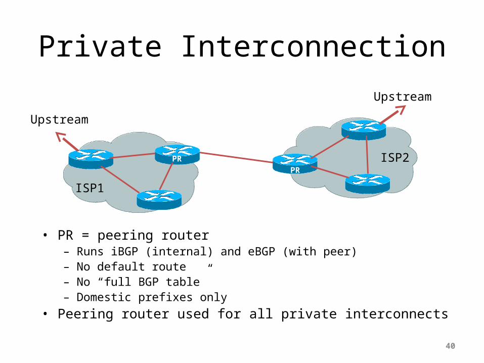
Private Interconnection
• PR = peering router– Runs iBGP (internal) and eBGP (with peer)– No default route– No “full BGP table”– Domestic prefixes only
• Peering router used for all private interconnects40
PRPR
ISP1
ISP2
Upstream
Upstream
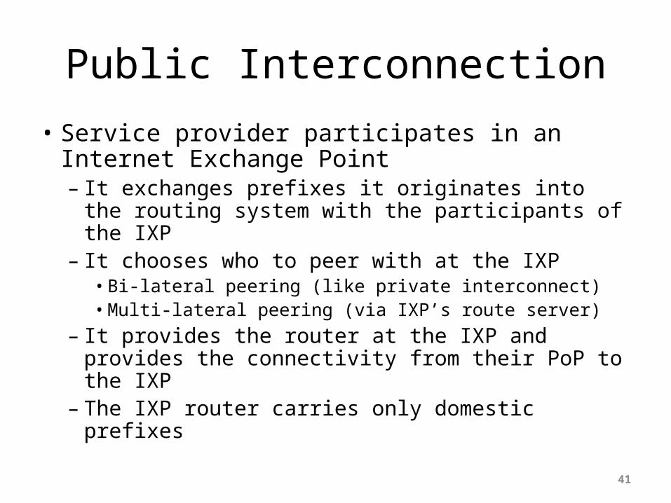
Public Interconnection
• Service provider participates in an Internet Exchange Point– It exchanges prefixes it originates into the routing
system with the participants of the IXP– It chooses who to peer with at the IXP• Bi-lateral peering (like private interconnect)• Multi-lateral peering (via IXP’s route server)
– It provides the router at the IXP and provides the connectivity from their PoP to the IXP
– The IXP router carries only domestic prefixes
41
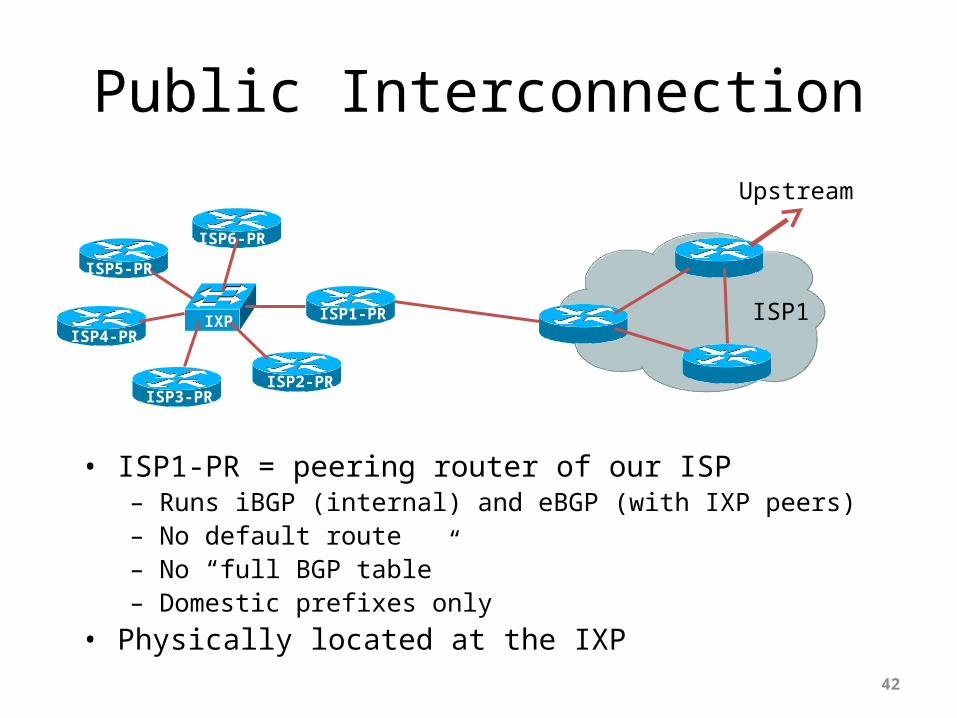
Public Interconnection
• ISP1-PR = peering router of our ISP– Runs iBGP (internal) and eBGP (with IXP peers)– No default route– No “full BGP table”– Domestic prefixes only
• Physically located at the IXP42
ISP1-PR ISP1
Upstream
IXP
ISP2-PRISP3-PR
ISP4-PR
ISP5-PR
ISP6-PR
Public Interconnection
• The ISP’s router IXP peering router needs careful configuration:– It is remote from the domestic backbone– Should not originate any domestic prefixes– (As well as no default route, no full BGP table)– Filtering of BGP announcements from IXP peers (in and out)
• Provision of a second link to the IXP:– (for redundancy or extra capacity)– Usually means installing a second router
• Connected to a second switch (if the IXP has two more more switches)• Interconnected with the original router (and part of iBGP mesh)
43
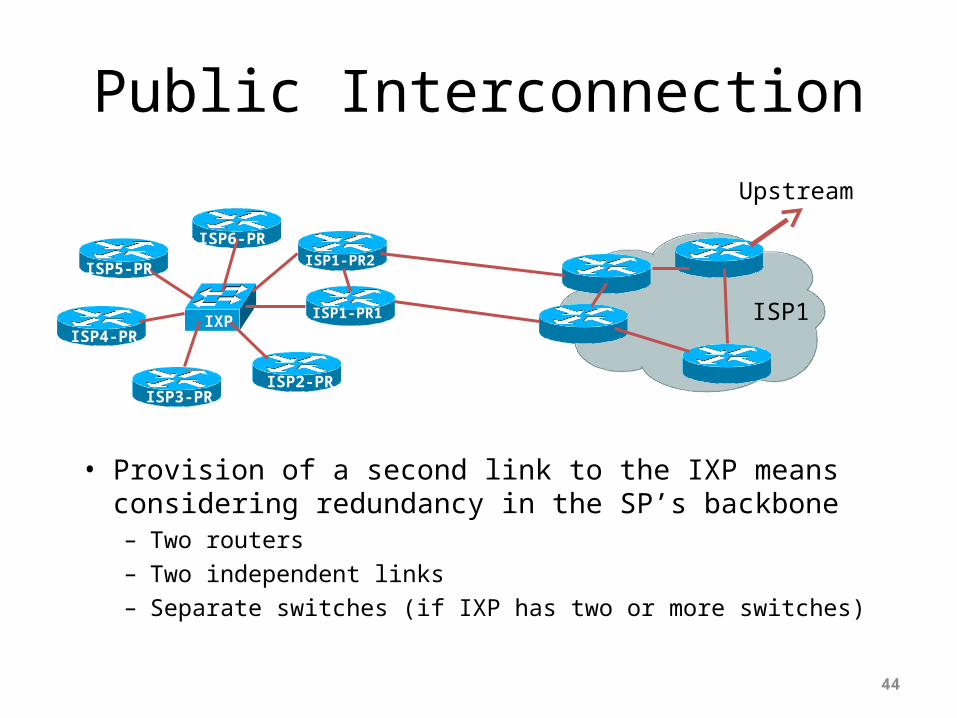
Public Interconnection
• Provision of a second link to the IXP means considering redundancy in the SP’s backbone– Two routers– Two independent links– Separate switches (if IXP has two or more switches)
44
ISP1-PR1 ISP1
Upstream
IXP
ISP2-PRISP3-PR
ISP4-PR
ISP5-PR
ISP6-PRISP1-PR2

Upstream/Transit Connection
• Two scenarios:– Transit provider is in the locality• Which means bandwidth is cheap, plentiful, easy to
provision, and easily upgraded
– Transit provider is a long distance away• Over undersea cable, satellite, long-haul cross country
fibre, etc
• Each scenario has different considerations which need to be accounted for
45

Local Transit Provider
• BR = ISP’s Border Router– Runs iBGP (internal) and eBGP (with transit)– Either receives default route or the full BGP table from upstream– BGP policies are implemented here (depending on connectivity)– Packet filtering is implemented here (as required)
46
ARBR
Transit
ISP1
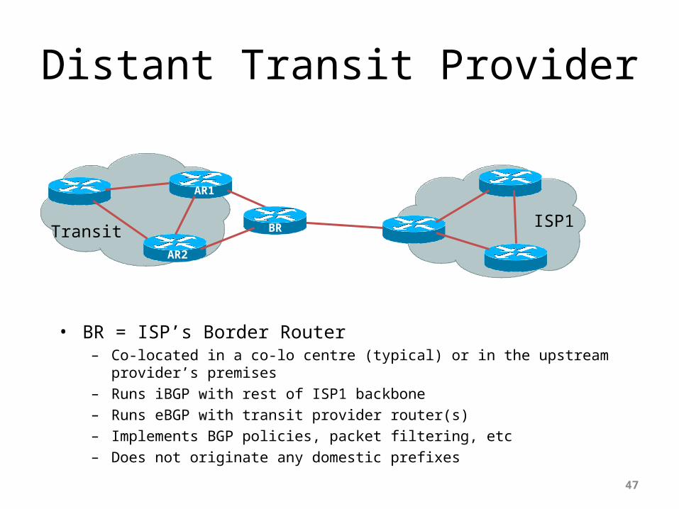
Distant Transit Provider
• BR = ISP’s Border Router– Co-located in a co-lo centre (typical) or in the upstream provider’s premises– Runs iBGP with rest of ISP1 backbone– Runs eBGP with transit provider router(s)– Implements BGP policies, packet filtering, etc– Does not originate any domestic prefixes
47
AR1
TransitISP1BR
AR2

Distant Transit Provider
• Positioning a router close to the Transit Provider’s infrastructure is strongly encouraged:– Long haul circuits are expensive, so the router allows
the ISP to implement appropriate filtering first– Moves the buffering problem away from the Transit
provider– Remote co-lo allows the ISP to choose another transit
provider and migrate connections with minimum downtime
48

Distant Transit Provider
• Other points to consider:– Does require remote hands support– (Remote hands would plug or unplug cables,
power cycle equipment, replace equipment, etc as instructed)
– Appropriate support contract from equipment vendor(s)
– Sensible to consider two routers and two long-haul links for redundancy
49
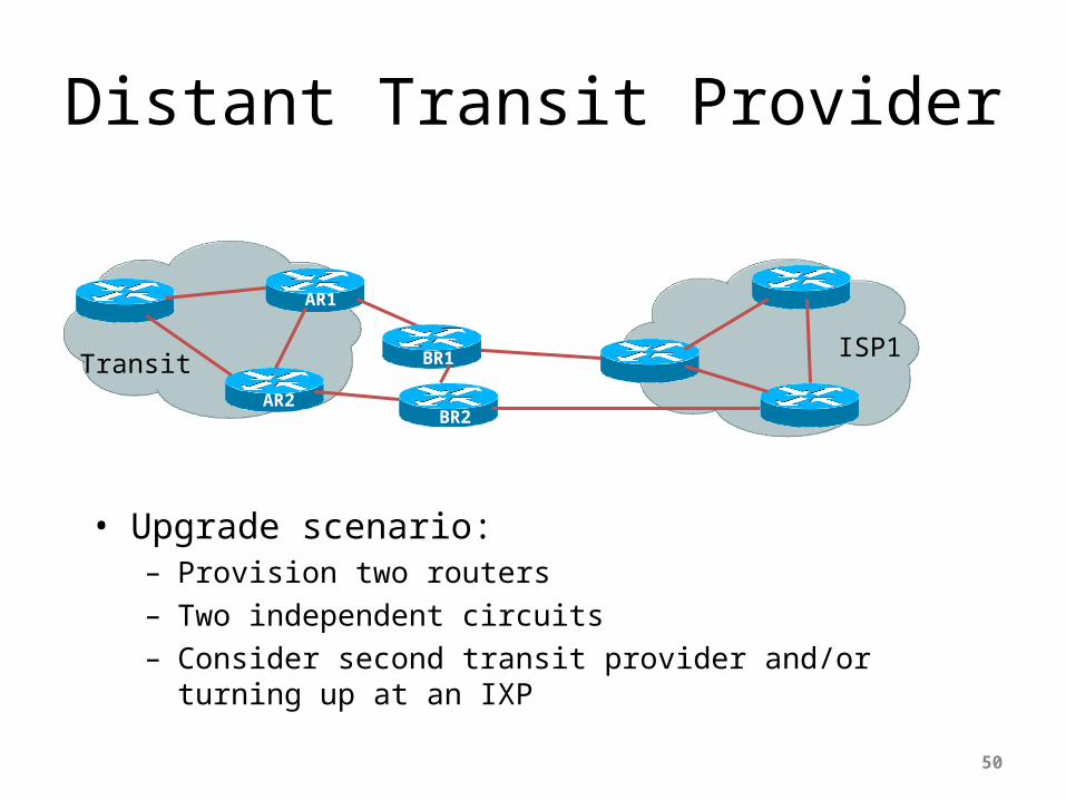
Distant Transit Provider
• Upgrade scenario:– Provision two routers– Two independent circuits– Consider second transit provider and/or turning up at an IXP
50
AR1
TransitISP1BR1
AR2BR2

Summary
• Design considerations for:– Private interconnects• Simple private peering
– Public interconnects• Router co-lo at an IXP
– Local transit provider• Simple upstream interconnect
– Long distance transit provider• Router remote co-lo at datacentre or Transit premises
51

Addressing
Addressing Resources and Protocols
52
Getting IP address space
• Take part of upstream ISP’s PA spaceor
• Become a member of your Regional Internet Registry and get your own allocation– Require a plan for a year ahead– General policies are outlined in RFC2050, more specific details are
on the individual RIR website
• There is no more IPv4 address space at IANA– Most RIRs are now entering their “final /8” IPv4 delegation policies– Limited IPv4 available– IPv6 allocations are simple to get in most RIR regions
53
What about RFC1918 addressing?
• RFC1918 defines IP addresses reserved for private Internets– Not to be used on Internet backbones– http://www.ietf.org/rfc/rfc1918.txt
• Commonly used within end-user networks– NAT used to translate from private internal to public external
addressing– Allows the end-user network to migrate ISPs without a major
internal renumbering exercise
• Most ISPs filter RFC1918 addressing at their network edge– http://www.cymru.com/Documents/bogon-list.html
54
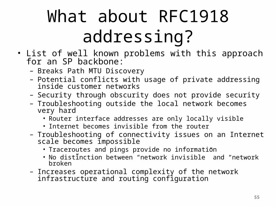
What about RFC1918 addressing?• List of well known problems with this approach for an SP
backbone:– Breaks Path MTU Discovery– Potential conflicts with usage of private addressing inside customer
networks– Security through obscurity does not provide security– Troubleshooting outside the local network becomes very hard
• Router interface addresses are only locally visible• Internet becomes invisible from the router
– Troubleshooting of connectivity issues on an Internet scale becomes impossible• Traceroutes and pings provide no information• No distinction between “network invisible” and “network broken”
– Increases operational complexity of the network infrastructure and routing configuration
55

Private versus Globally Routable IP Addressing
• Infrastructure Security: not improved by using private addressing– Still can be attacked from inside, or from customers, or by reflection
techniques from the outside
• Troubleshooting: made an order of magnitude harder– No Internet view from routers– Other ISPs cannot distinguish between down and broken
• Performance: PMTUD breakage• Summary:
– ALWAYS use globally routable IP addressing for ISP Infrastructure
56
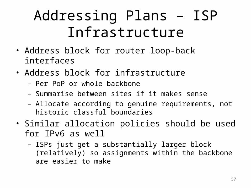
Addressing Plans – ISP Infrastructure
• Address block for router loop-back interfaces• Address block for infrastructure
– Per PoP or whole backbone– Summarise between sites if it makes sense– Allocate according to genuine requirements, not historic classful
boundaries
• Similar allocation policies should be used for IPv6 as well– ISPs just get a substantially larger block (relatively) so assignments
within the backbone are easier to make
57
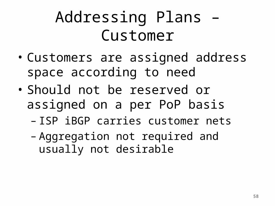
Addressing Plans – Customer
• Customers are assigned address space according to need
• Should not be reserved or assigned on a per PoP basis– ISP iBGP carries customer nets– Aggregation not required and usually not
desirable
58
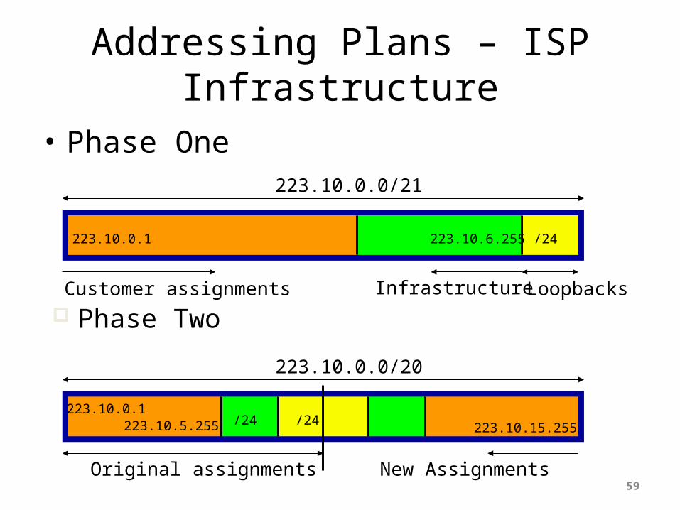
Phase Two
Addressing Plans – ISP Infrastructure
• Phase One
59
223.10.0.0/21
Customer assignments Infrastructure Loopbacks
/24223.10.6.255223.10.0.1
223.10.0.0/20
Original assignments New Assignments
/24/24223.10.0.1
223.10.5.255 223.10.15.255

Addressing PlansPlanning
• Registries will usually allocate the next block to be contiguous with the first allocation– Minimum allocation could be /21– Very likely that subsequent allocation will make
this up to a /20– So plan accordingly
60
Addressing Plans (contd)
• Document infrastructure allocation– Eases operation, debugging and management
• Document customer allocation– Contained in iBGP– Eases operation, debugging and management– Submit network object to RIR Database
61
Routing Protocols
62

Routing Protocols
• IGP – Interior Gateway Protocol– carries infrastructure addresses, point-to-point
links– examples are OSPF, ISIS,...
• EGP – Exterior Gateway Protocol– carries customer prefixes and Internet routes– current EGP is BGP version 4
• No connection between IGP and EGP
63
Why Do We Need an IGP?
• ISP backbone scaling– Hierarchy– Modular infrastructure construction– Limiting scope of failure– Healing of infrastructure faults using dynamic
routing with fast convergence
64

Why Do We Need an EGP?
• Scaling to large network– Hierarchy– Limit scope of failure
• Policy– Control reachability to prefixes– Merge separate organizations– Connect multiple IGPs
65

Interior versus Exterior Routing Protocols
• Interior– Automatic neighbour
discovery– Generally trust your IGP
routers– Prefixes go to all IGP routers– Binds routers in one AS
together
• Exterior– Specifically configured peers– Connecting with outside
networks– Set administrative boundaries– Binds AS’s together
66
Interior versus Exterior Routing Protocols
• Interior– Carries ISP infrastructure
addresses only– ISPs aim to keep the IGP small
for efficiency and scalability
• Exterior– Carries customer prefixes– Carries Internet prefixes– EGPs are independent of ISP
network topology
67

Hierarchy of Routing Protocols
68
BGP4
BGP4and OSPF/ISIS
Other ISPs
CustomersIXP
Static/BGP4
BGP4

Routing Protocols:Choosing an IGP
• Review the “OSPF vs ISIS” presentation:– OSPF and ISIS have very similar properties
• ISP usually chooses between OSPF and ISIS– Choose which is appropriate for your operators’
experience– In most vendor releases, both OSPF and ISIS have
sufficient “nerd knobs” to tweak the IGP’s behaviour
– OSPF runs on IP– ISIS runs on infrastructure, alongside IP
69
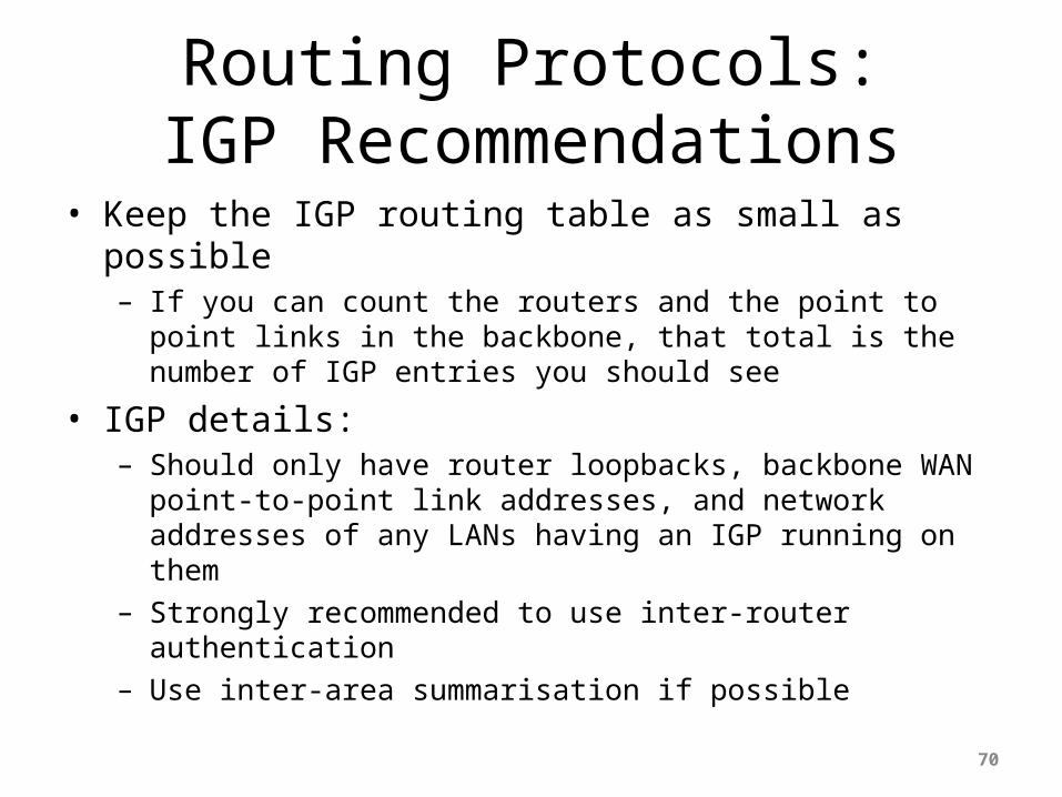
Routing Protocols:IGP Recommendations
• Keep the IGP routing table as small as possible– If you can count the routers and the point to point links in the
backbone, that total is the number of IGP entries you should see
• IGP details:– Should only have router loopbacks, backbone WAN point-to-point link
addresses, and network addresses of any LANs having an IGP running on them
– Strongly recommended to use inter-router authentication– Use inter-area summarisation if possible
70

Routing Protocols:More IGP recommendations
• To fine tune IGP table size more, consider:– Using “ip unnumbered” on customer point-to-
point links – saves carrying that /30 in IGP• (If customer point-to-point /30 is required for
monitoring purposes, then put this in iBGP)– Use contiguous addresses for backbone WAN links
in each area – then summarise into backbone area– Don’t summarise router loopback addresses – as
iBGP needs those (for next-hop)– Use iBGP for carrying anything which does not
contribute to the IGP Routing process71

Routing Protocols:iBGP Recommendations
• iBGP should carry everything which doesn’t contribute to the IGP routing process– Internet routing table– Customer assigned addresses– Customer point-to-point links– Dial network pools, passive LANs, etc
72
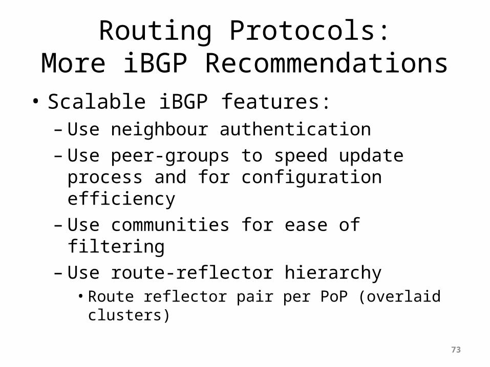
Routing Protocols:More iBGP Recommendations
• Scalable iBGP features:– Use neighbour authentication– Use peer-groups to speed update process and for
configuration efficiency– Use communities for ease of filtering– Use route-reflector hierarchy• Route reflector pair per PoP (overlaid clusters)
73

Security
74

Security
• ISP Infrastructure security• ISP Network security• Security is not optional!• ISPs need to:
– Protect themselves– Help protect their customers from the Internet– Protect the Internet from their customers
• The following slides are general recommendations– Do more research on security before deploying any network
75

ISP Infrastructure Security
• Router security– Usernames, passwords, vty filters, TACACS+– Disable telnet on vtys, only use SSH– vty filters should only allow NOC access, no
external access– See IOS Essentials for the recommended practices
for ISPs
76

ISP Network Security
• Denial of Service Attacks– eg: “smurfing”– see http://www.denialinfo.com
• Effective filtering– Network borders – see Cisco ISP Essentials– Static customer connections – unicast RPF on ALL
of them– Network operation centre– ISP corporate network – behind firewall
77

Ingress & Egress Route Filtering
Your customers should not be sending any IP packets out to the Internet with
a source address other then the address you have allocated to them!
78

Out of Band Management
79

Out of Band Management
• Not optional!• Allows access to network equipment in times
of failure• Ensures quality of service to customers– Minimises downtime– Minimises repair time– Eases diagnostics and debugging
80

Out of Band Management
• OoB Example – Access server:– modem attached to allow NOC dial in– console ports of all network equipment connected
to serial ports– LAN and/or WAN link connects to network core,
or via separate management link to NOC
• Full remote control access under all circumstances
81

Out of Band Network
82
Ethernetto the NOC
Router, switchand ISP server
consoles
(Optional) Out of bandWAN link to other PoPs
Modem – accessto PSTN for out of
band dialin
Equipment RackEquipment Rack
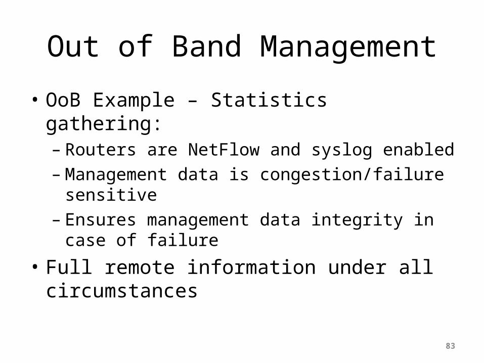
Out of Band Management
• OoB Example – Statistics gathering:– Routers are NetFlow and syslog enabled– Management data is congestion/failure sensitive– Ensures management data integrity in case of
failure
• Full remote information under all circumstances
83

Test Laboratory
84

Test Laboratory
• Designed to look like a typical PoP– Operated like a typical PoP
• Used to trial new services or new software under realistic conditions
• Allows discovery and fixing of potential problems before they are introduced to the network
85
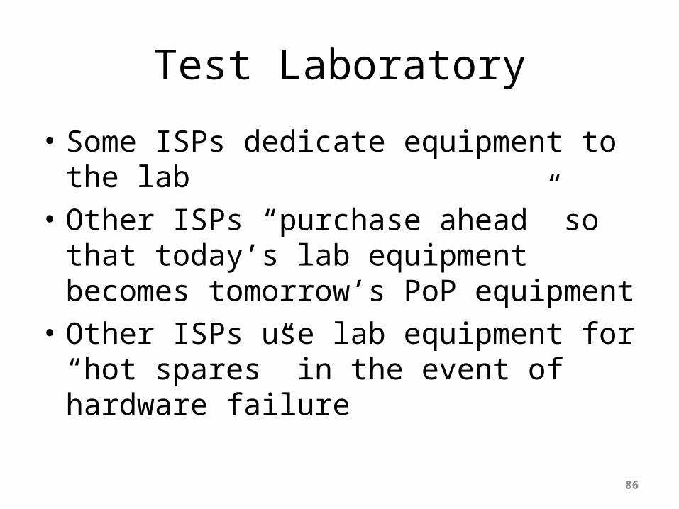
Test Laboratory
• Some ISPs dedicate equipment to the lab• Other ISPs “purchase ahead” so that today’s
lab equipment becomes tomorrow’s PoP equipment
• Other ISPs use lab equipment for “hot spares” in the event of hardware failure
86

Test Laboratory
• Can’t afford a test lab?– Set aside one spare router and server to trial new
services– Never ever try out new hardware, software or
services on the live network
• Every major ISP in the US and Europe has a test lab– It’s a serious consideration
87

Operational Considerations
88
Operational Considerations
89
Why design the world’s best network when you have not
thought about what operational good practices should be
implemented?
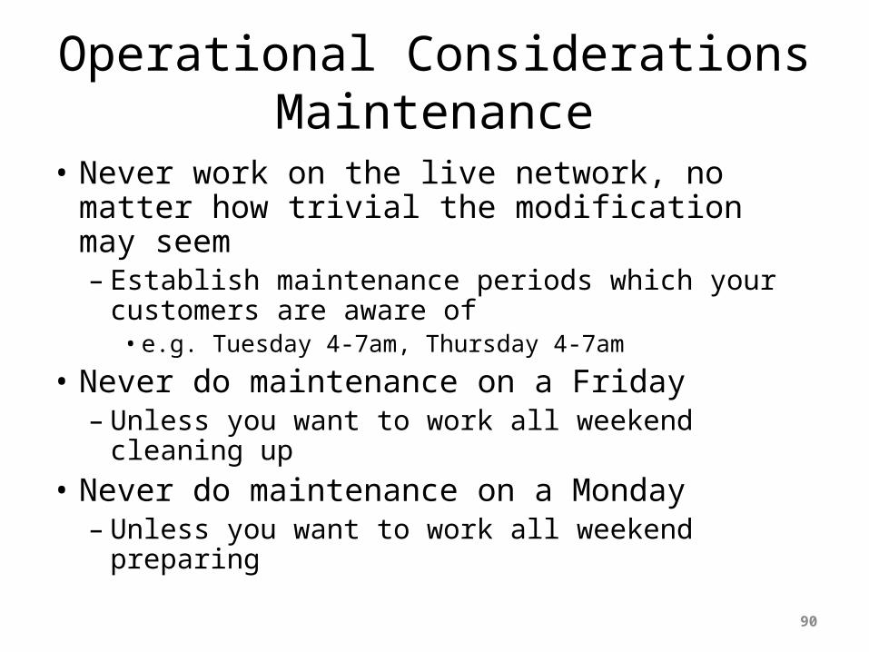
Operational ConsiderationsMaintenance
• Never work on the live network, no matter how trivial the modification may seem– Establish maintenance periods which your
customers are aware of• e.g. Tuesday 4-7am, Thursday 4-7am
• Never do maintenance on a Friday – Unless you want to work all weekend cleaning up
• Never do maintenance on a Monday– Unless you want to work all weekend preparing
90

Operational ConsiderationsSupport
• Differentiate between customer support and the Network Operations Centre– Customer support fixes customer problems– NOC deals with and fixes backbone and Internet
related problems• Network Engineering team is last resort– They design the next generation network, improve
the routing design, implement new services, etc– They do not and should not be doing support!
91

Operational ConsiderationsNOC Communications
• NOC should know contact details for equivalent NOCs in upstream providers and peers
• Or consider joining the INOC-DBA system– Voice over IP phone system using SIP– Runs over the Internet– www.pch.net/inoc-dba for more information
92
ISP Network Design
Summary
93

ISP Design Summary
• KEEP IT SIMPLE & STUPID ! (KISS)• Simple is elegant is scalable• Use Redundancy, Security, and Technology to
make life easier for yourself• Above all, ensure quality of service for your
customers
94
Acknowledgement and Attribution
This presentation contains content and information originally developed and maintained by the following organisation(s)/individual(s) and provided for the African Union AXIS Project
Philip Smith: - [email protected]
Cisco ISP/IXP Workshops
www.apnic.net

ISP Network Design
Scalable Network Design
96


