A. Starčev-Ćurčin i dr. Program "ST method" za određivanje Strut-and-Tie modela ravninskih AB nosača Tehnički vjesnik 23, 1(2016), 291-300 291 ISSN 1330-3651 (Print), ISSN 1848-6339 (Online) DOI: 10.17559/TV-20140818132418 THE PROGRAM "ST METHOD" FOR DETERMINING THE STRUT-AND-TIE MODELS OF RC PLANE MEMBERS Anka Starčev-Ćurčin, Andrija Rašeta, Zoran Brujić Preliminary notes The paper presents a proposal for determining the Strut-and-Tie models of reinforced concrete plane members using the discrete topology optimization, which involves the truss system for calculation of the stress-strain state of a real member. Strut-and-Tie model can be used for the analysis of both a single part and the entire member, and is particularly suitable for application in cases where an abrupt change of static values and geometrical properties of the member occurs. Based on the presented proposal, the program "ST method" is developed and can automatically determine the final shape of the Strut- and-Tie model, stress control of the model elements and the required amount of reinforcement. Moreover, the reinforcement amount optimization of the Strut-and-Tie models is presented in the paper. Keywords: optimization; "ST method"; Strut-and-Tie Program "ST method" za određivanje Strut-and-Tie modela ravninskih AB nosača Prethodno priopćenje U radu je predstavljen prijedlog za određivanje Strut-and-Tie modela armiranobetonskih ravninskih nosača primjenom diskretne topološke optimizacije koja podrazumijeva rešetkasti sustav za proračun stanja naprezanje-deformacija nosača. Strut-and-Tie model se može koristiti pri analizi dijela ili cijelog nosača, a posebno je pogodan na mjestima naglih promjena statičkih veličina i/ili geometrijskih karakteristika nosača. Na osnovu prikazanog prijedloga, razvijen je program "ST method" pomoću kojeg se može automatski odrediti konačan oblik Strut-and-Tie modela, izvršiti kontrola naprezanja u elementima modela i odrediti potrebna količina armature. Također, u radu je prikazana i optimizacija Strut-and-Tie modela prema potrebnoj količini armature. Ključne riječi: optimizacija; "ST metoda"; Strut-and-Tie 1 Introduction The Strut-and-Tie method has been undergoing its development process for more than a hundred years with pioneers Hennebique, Ritter and Mörsch, along with many other researchers including Schlaich, Vecchio, Reineck, Muttoni, Kuchma etc. The method is introduced in the Canadian Standards Associations (CSA) and LRDF AASHTO Bridge Design Specifications [1], American Standard ACI 318 [2], Europen Standards [3], [4] and EN 1992 [5], etc. The main purpose of the Strut-and-Tie method is the accurate and fast analysis of the stress- strain state of an element in the cases where application of conventional analysis methods is very complex and impractical. Also, optimization has an important application in streamlining design to minimise material consumption while providing the capacity, stability and usability. The need for this analysis occurs in either a part or the entire member, and is particularly suitable for applying in an abrupt change of static values and/or geometrical properties of the member. Typical examples of the members where this approach can be successfully applied for the analysis and dimensioning are: a single foundation, pile cap, stiffening cross sections diaphragm, wall members with and without holes, abutment shear wall of bridges, places with sudden changes of cross- sectional geometry (for example, sudden reduction in cross section at the end of the member), places where large concentrated loads are applied (cable pylon anchoring zone in cable-stayed bridges), boards relying on posts (trouble with breaking the column through the plate), short elements, etc. Technical theory of bending covers the dimensioning of reinforced concrete members in the cases when all the static values of the element lengthwise axis change gradually the so-called B-regions or, according to the Bernoulli hypothesis, the linear strain distribution in the section. In the cases of discontinuity of the so-called D- regions that occur in the places of abrupt changes of static values and/or geometry of the member, the common analysis and dimensioning cannot be used (see Fig. 1), [6] and [7]. These regions are practically solved by relying upon structural engineering experience and recommendations, which can result in poorly-designed and performed construction details that affect the quality of the whole structure. As a result, a need arises for D- regions to be analyzed using a simple and rational model, with the Strut-and-Tie method being one of these, providing an insight into the real behavior of reinforced concrete elements, their parts or the whole. The positions of B and D regions are determined by St. Venant's rules. This means that the local stress field disturbance, affected by the concentrated force, the proximity to the support or abrupt changes in the geometry, is lost in a distance approximately equal to the height of the element. Figure 1 B and D regions of the member
Transcript
A. Starčev-Ćurčin i dr. Program "ST method" za određivanje Strut-and-Tie modela ravninskih AB nosača
THE PROGRAM "ST METHOD" FOR DETERMINING THE STRUT-AND-TIE MODELS OF RC PLANE MEMBERS Anka Starčev-Ćurčin, Andrija Rašeta, Zoran Brujić
Preliminary notes The paper presents a proposal for determining the Strut-and-Tie models of reinforced concrete plane members using the discrete topology optimization, which involves the truss system for calculation of the stress-strain state of a real member. Strut-and-Tie model can be used for the analysis of both a single part and the entire member, and is particularly suitable for application in cases where an abrupt change of static values and geometrical properties of the member occurs. Based on the presented proposal, the program "ST method" is developed and can automatically determine the final shape of the Strut-and-Tie model, stress control of the model elements and the required amount of reinforcement. Moreover, the reinforcement amount optimization of the Strut-and-Tie models is presented in the paper. Keywords: optimization; "ST method"; Strut-and-Tie Program "ST method" za određivanje Strut-and-Tie modela ravninskih AB nosača
Prethodno priopćenje U radu je predstavljen prijedlog za određivanje Strut-and-Tie modela armiranobetonskih ravninskih nosača primjenom diskretne topološke optimizacije koja podrazumijeva rešetkasti sustav za proračun stanja naprezanje-deformacija nosača. Strut-and-Tie model se može koristiti pri analizi dijela ili cijelog nosača, a posebno je pogodan na mjestima naglih promjena statičkih veličina i/ili geometrijskih karakteristika nosača. Na osnovu prikazanog prijedloga, razvijen je program "ST method" pomoću kojeg se može automatski odrediti konačan oblik Strut-and-Tie modela, izvršiti kontrola naprezanja u elementima modela i odrediti potrebna količina armature. Također, u radu je prikazana i optimizacija Strut-and-Tie modela prema potrebnoj količini armature. Ključne riječi: optimizacija; "ST metoda"; Strut-and-Tie 1 Introduction
The Strut-and-Tie method has been undergoing its development process for more than a hundred years with pioneers Hennebique, Ritter and Mörsch, along with many other researchers including Schlaich, Vecchio, Reineck, Muttoni, Kuchma etc. The method is introduced in the Canadian Standards Associations (CSA) and LRDF AASHTO Bridge Design Specifications [1], American Standard ACI 318 [2], Europen Standards [3], [4] and EN 1992 [5], etc. The main purpose of the Strut-and-Tie method is the accurate and fast analysis of the stress-strain state of an element in the cases where application of conventional analysis methods is very complex and impractical. Also, optimization has an important application in streamlining design to minimise material consumption while providing the capacity, stability and usability. The need for this analysis occurs in either a part or the entire member, and is particularly suitable for applying in an abrupt change of static values and/or geometrical properties of the member. Typical examples of the members where this approach can be successfully applied for the analysis and dimensioning are: a single foundation, pile cap, stiffening cross sections diaphragm, wall members with and without holes, abutment shear wall of bridges, places with sudden changes of cross-sectional geometry (for example, sudden reduction in cross section at the end of the member), places where large concentrated loads are applied (cable pylon anchoring zone in cable-stayed bridges), boards relying on posts (trouble with breaking the column through the plate), short elements, etc.
Technical theory of bending covers the dimensioning of reinforced concrete members in the cases when all the static values of the element lengthwise axis change
gradually the so-called B-regions or, according to the Bernoulli hypothesis, the linear strain distribution in the section. In the cases of discontinuity of the so-called D-regions that occur in the places of abrupt changes of static values and/or geometry of the member, the common analysis and dimensioning cannot be used (see Fig. 1), [6] and [7]. These regions are practically solved by relying upon structural engineering experience and recommendations, which can result in poorly-designed and performed construction details that affect the quality of the whole structure. As a result, a need arises for D-regions to be analyzed using a simple and rational model, with the Strut-and-Tie method being one of these, providing an insight into the real behavior of reinforced concrete elements, their parts or the whole.
The positions of B and D regions are determined by St. Venant's rules. This means that the local stress field disturbance, affected by the concentrated force, the proximity to the support or abrupt changes in the geometry, is lost in a distance approximately equal to the height of the element.
Figure 1 B and D regions of the member
The program "ST method" for determining the Strut-and-Tie models of RC plane members A. Starčev-Ćurčin et al.
292 Technical Gazette 23, 1(2016), 291-300
Optimization of reinforced concrete members can be made according to their topology and geometry [8]. The design concept of this kind of optimization is based on the discrete and continuum optimization. Discrete optimization involves modeling of a member with the finite element system, whereas continuum optimization takes into account the member as a continuum.
This paper presents a proposal for determining the Strut-and-Tie models of reinforced concrete plane members using the discrete topology optimization which involves the truss system for calculation of the stress-strain state of the real member. The program "ST method", which can automatically determine the final shape of the Strut-and-Tie model, the stress control of the model elements and the required amount of reinforcement, has thus been developed. The reinforcement amount optimization of the Strut-and-Tie models is presented. 2 The proposal method for determining Strut-and-Tie
model
General concept of determining the optimal design form of the initial configuration of a system involves exclusion of certain parts of a member from the load transfer, based on predetermined parameters (stress, stiffness, etc.). There are discrete and continuum optimizations. Discrete optimization replaces the whole member with a finite number of elements, while continuum optimization works with specially arranged material that is difficult to present with the finite geometric characteristics [8], [9] and [10].
By discrete topology optimization, a member can be modeled with the truss system, such as Strut-and-Tie model. An example of optimized reinforced concrete member is shown in Fig. 5.
The program "ST method" has been developed for the application of discrete topology optimization, with the ability to analyze an RC member in the plane. During the development of the program, the removal of the individual elements of the truss system, whose participation in the load transfer during iterations are no longer important for determining the Strut-and-Tie model, was automatically attempted. This approach resulted in the possible occurrence of system instability that was present at the time of the removal of a single truss element. In order to maintain the stability of the system during the iteration, achieving at the same time force redistribution in the elements, the correction procedure of cross-sections area was applied. It was based on the character of axial forces in the simple elements according to the Eq. (2) but with a minimum limit of the cross section. Reduction in cross-sectional area of each truss element during iterations is limited to the minimum value determined indirectly through a predefined minimum force that the element can carry. Analyses have shown that it is sufficient to adopt the minimum force that a truss element can transfer to the value of 0,1 ‰ of the absolute maximum force value which might appear in the elements of the zero analysis iteration. This value was recommended by the authors of this paper .
Analysis of a member with discrete topological optimization according to the stiffness of individual
elements of the truss system is described in [10, 11, 12, 13, 14, 15]. In the design of reinforced concrete members, the least amount of reinforcement is one of the most common optimization conditions. Based on these facts, stiffness of individual elements, i.e. simple elements, of the model is determined by the expression, Eq. (1), according to [13] and [14]:
, 1,
d i ji j i
i d
E NK
L fβ −= (1)
where: βi – is the reduction factor which depends on the required ("desired") reinforcement layout in the member (values range from 0 to 1) ; Ni,j−1 – is the force in the ith simple element from j−1 iteration ; Ed – is the modulus of elasticity for concrete (pressure) or steel (tension) ; fd – is design strength of the tensioned reinforcement or the compressed concrete depending on the nature of the axial force in the truss element (pressure-concrete or tension-steel) ; Li – is the length of the element.
The value of β coefficient depends on the angle of desired reinforcement inclination. With the adoption of larger β coefficient values (close to 1) in the analysis, it can be possible to favour directions in the transfer of tensil forces. The values of β coefficient for the pressure struts are always 1, because there are no favourite directions for the pressure forces transfer. The recommended values of β coefficients for tensioned truss elements, i.e. ties, are 1 for 0°, 45° and 90°, and 0 for other angles.
This approach involves an iterative calculation in which the re-stiffness calculation of individual elements is performed at each step, based on the analysis results from the previous step.
Discrete optimization procedure, proposed in the paper, uses the correction of axial stiffness of the cross section of simple elements (EA), depending on the nature and intensity of stress. The stiffness element changing is made indirectly through changes in the cross-sectional area. The cross-sectional area of individual elements, the simple truss elements, is determined with the expression according to [14], modified by the authors of this paper:
, 1,
i ji j i
d
NA
fβ −= (2)
where parameters from Eq. (2) have the same meaning as in Eq. (1).
The modulus of elasticity of individual truss elements shall be adopted depending on the nature of the axial force (pressure – concrete or tension – steel). The analysis is carried out iteratively. In the zero iteration a network of finite elements (truss element) is created with boundary conditions (support nodes in the system) and the external loads (concentrated forces in the nodes of the system). The considered domain is modeled by the mentioned network. All model elements have the same mechanical and geometrical characteristics of the cross sections. The axial forces in the elements are determined on the established model. Based on the character of the axial forces (pressure or tension), the area of the cross sections is determined for all the elements according to the Eq. (2),
A. Starčev-Ćurčin i dr. Program "ST method" za određivanje Strut-and-Tie modela ravninskih AB nosača
Tehnički vjesnik 23, 1(2016), 291-300 293
which specifies the corresponding modulus for each simple element individually (pressure – concrete or tension – steel). In this way, the model is formed for the next iteration. For each successive iteration, the model that is used is obtained based on the correction of axial stiffness of the cross section of truss elements carried on the character and intensity of the axial forces in the elements from the previous iteration. The convergence of the calculations is determined in the numerical sense by the change in the estimated stiffness of the system between two adjacent calculation iterations. Assessment of model stiffness at the end of each iteration is defined as the product of the values on the main diagonal of the element system stiffness matrix. The change in the estimated model stiffness between two consecutive iterations is determined by the expression:
1
( )( )
SS j
SS j
K KK
K K −∆ = (3)
where: K(K SS)j−1 – is the estimated stiffness of the system in the j−1 iteration ; K(K SS)j – is the estimated stiffness of the system in the j iteration.
Value ΔK changes from zero to one, though the iteration tends to 1,0 "from the bottom". The analysis stops at the time of fulfillment of the conditions defined by the following inequality:
1K ε∆ ≥ − (4) where: ε – is the value used to pre-define the difference stating that the system has remained invariable between two adjacent iterations. The recommended value, by the paper authors, of the parameter ε is 1 %. Also, the maximum number of iterations is determined as an additional condition for the termination of the analysis. Calculations show that the value of the maximum number of iterations is sufficient to be limited by the number of truss elements in the system. The shapes of the Strut-and-Tie models for several examples of reinforced concrete plane members obtained according to the above described proposal method have been shown in [16].
3 The concept of "ST method" Based on the previously described proposal for
discrete topology optimization, the program "ST method" has been developed, with the ability to analyze an RC member in the plane. The Flowchart of the adopted optimal design procedure, implemented in the program "ST method", is shown in Fig. 2.
Figure 2 The Flowchart of the adopted procedure
The program is based on a graphical user interface
(GUI). On entering, the finite element mesh, boundary conditions and external loads are defined in the program in the form of "FEM", which is shown in Fig. 3-left. The "FEM" window offers several different options for automatic generation of finite elements of complex contours with or without holes. The option for auto-generating nodes and simple elements (Tab "Automatic Entry") is a substantial time-saver required for the generation of finite elements with respect to models with a small number of nodes that can have a significant number of truss elements, due to the conditions of mutual connection of all nodes in the model. The network can be formed from individual parts or as a whole, where the holes are then "made".
Figure 3 The user interface for input of finite elements, boundary conditions and loads (left) and for the analysis parameters settings (right)
The program "ST method" for determining the Strut-and-Tie models of RC plane members A. Starčev-Ćurčin et al.
294 Technical Gazette 23, 1(2016), 291-300
Figure 4 The user interface for adjusting graphic model presentation (left) and the user interface for text display (right)
Analysis parameters are set in the "Control of
Analysis" (see Fig. 3-right). This window has input fields for β reduction coefficients whose combination values can affect the shape of the Strut-and-Tie model. It is possible to enter five different β coefficients depending on the angle of the inclination of truss elements. In particular, the β value of compressed elements is always 1,whereas tensioned elements at an angle of 0°, 45° and 90°, as well as other tensioned elements, are defined with values from 0 to 1. Also, the important parameters in this form, the values for the convergence of the design ("Variability of the system") and the minimum limits of the cross-sectional area of a truss element ("Zero Force"), are defined.
Graphics for model inputs and results of the analysis can be controlled in the "Graphic" window (see Fig. 4-left). There is a possibility to control the presentation of the model, boundary conditions, loads, visual and text node information, truss elements, etc.
The program has the ability to display text input model and the results of the analysis in the "Text Results" window (see Fig. 4-right). Input and output data can be displayed separately for each recorded iteration of the design with a choice of data types (axial force in the truss
element, the reactions of supports, displacements of nodes, stiffness matrix of truss elements). In the "Design" window there is a possibility of determining the required reinforcement of the RC member and the stress control of the model elements (see Fig. 7). Based on the adopted input material properties and the automatically determined Strut-and-Tie model, the reinforcement in the layout of the tensioned truss elements is calculated, along with its equivalent reinforcement in horizontal and vertical directions. 4 Working with "ST method"
Working with the "ST method" can be divided into several main phases that include: input material properties, formation of finite element mesh, analysis, presentation of results and dimensioning of the member. The formation of a finite element mesh is done by using "tools" in the "FEM" form (see Fig. 3-left). Along with the gradual formation of the model, there is a possibility of its visual presentation. This facilitates the input and control of the network parameters. Fig. 5-left shows an example of the formed analysis model at the program desktop.
Figure 5 The desktop of the program "ST method" – FEM (left) and the desktop with the Strut-and-Tie model (right)
Figure 6 The desktop of the program with the characteristic iterations
A. Starčev-Ćurčin i dr. Program "ST method" za određivanje Strut-and-Tie modela ravninskih AB nosača
Tehnički vjesnik 23, 1(2016), 291-300 295
In the next phase, which is related to the analysis, the first step is to define the control parameters for design in the form of "Control of Analysis" (see Fig. 3-right). Then, in the second step, the analysis starts. It should be noted that this iterative calculation can be tiresome for more complex models, because in each iteration the new characteristics of the truss elements are set again according to the Eq. (2), which results in the re-establishment of the system stiffness matrix. The newly formed system solves and determines the forces in the truss elements. Because of the characteristic design phases in each iteration, this analysis, which is linear, "reminds" of a non-linear analysis. The results can be shown textually and graphically for each recorded calculated iteration (see Fig. 6).
Fig. 5-right shows the graphic of an automatically determined Strut-and-Tie model with the forces of truss elements and support reactions. Graphic model inputs as well as results of the analysis can be controlled in the "Graphic" window (see Fig. 4-left).
The presented Strut-and-Tie model in Fig. 5-right can be used further on for dimensioning with the use of "tools" defined in the "Design" window (see Fig. 7). The window allows determination of required reinforcement in the direction of simple truss tensioned elements and their equivalent horizontal and vertical reinforcement in the member, as well as stress control of the model elements.
Figure 7 The window for determination of the required reinforcement in the Strut-and-Tie Model
5 Numerical analysis 5.1 Strut-and-Tie model determination
Comparative analysis for determination of the Strut-
and-Tie model shapes is also done in the commercial program Ansys v15 (finite element PLANE82). The principle of the commercial program is assigning of the maximum removal percentage material conditions in relation to the initial volume of the member. For example, assigning of 70 % means that 70 % of the material has to be removed in a manner that maximizes the stiffness of
the given member and load configuration [17]. In this Chapter the examples were counted in the commercial program with the condition that the maximum permitted material removal from the initial member volume is 80 %.
The first example is a deep reinforced concrete beam with a hole, whose geometrical and mechanical characteristics are shown in Tab. 1. The member is loaded symmetrically with two vertical concentrated forces. The Strut-and-Tie model with the forces in the truss elements and the support reactions is shown in Fig. 8.
Table 1 Deep RC beam with a hole Member Static system Parameters for analysis
Ec = 31 GPa, Es = 200 GPa Compressed element β = 1 Tensioned element (0°) β = 1 Tensioned element (45°) β = 1 Tensioned element (90°) β = 1 Tensioned element (other angles) β = 0,01 num. of nodes 45 num. of elements 401
The program "ST method" for determining the Strut-and-Tie models of RC plane members A. Starčev-Ćurčin et al.
296 Technical Gazette 23, 1(2016), 291-300
Figure 8 Deep RC beam with a hole – Strut-and-Tie model obtained by "ST method" (left) and Commercial Program (right)
The second example is a shear reinforced concrete
wall, whose geometrical and mechanical characteristics are shown in Tab. 2, loaded with a horizontal force in the
level of the wall top. The Strut-and-Tie model with the forces in the truss elements and the support reactions is shown in Fig. 9.
Table 2 Shear RC wall Member Static system Parameters for analysis
Ec = 31 GPa, Es = 200 GPa Compressed element β = 1 Tensioned element (0°) β = 1 Tensioned element (45°) β = 1 Tensioned element (90°) β = 1 Tensioned element (other angles) β = 0,01 num. of nodes 45 num. of elements 632
Figure 9 Shear RC wall – Strut-and-Tie model obtained by "ST method" (left) and Commercial Program (right)
The third example is a reinforced concrete beam with
openings, whose geometrical and mechanical characteristics are shown in Tab. 3. It is loaded with three
vertical concentrated forces. The Strut-and-Tie model with the forces in the truss elements and the support reactions is shown in Fig. 10.
Table 3 RC beam with the holes Member Static system Parameters for analysis
Ec = 30 GPa, Es = 200 GPa Compressed element β = 1 Tensioned element (0°) β = 1 Tensioned element (45°) β = 1 Tensioned element (90°) β = 1 Tensioned element (other angles) β = 0,01 num. of nodes 75 num. of elements 1057
The fourth example is a deep RC concrete beam
whose geometrical and mechanical characteristics are shown in Tab. 4. It is loaded with vertical force of 5000 kN applied at the end of the overhang. The Strut-
and-Tie model with the forces in the truss elements and the support reactions is shown in Fig. 11.
Figs. 8, 9, 10 and 11 show that the Strut-and-Tie models determined by the "ST method" correspond to the shapes obtained by the commercial program.
A. Starčev-Ćurčin i dr. Program "ST method" za određivanje Strut-and-Tie modela ravninskih AB nosača
Tehnički vjesnik 23, 1(2016), 291-300 297
Figure 10 RC beam with the holes – Strut-and-Tie model obtained by "ST method" (left) and Commercial Program (right)
Table 4 RC beam with the holes
Member Static system Parameters for analysis
Ec = 30 GPa, Es = 200 GPa Compressed element β = 1 Tensioned element (0°) β = 1 Tensioned element (45°) β = 1 Tensioned element (90°) β = 1 Tensioned element (other angles) β = 0,01 num. of nodes 75 num. of elements 1057
Figure 11 Deep RC concrete beam – Strut-and-Tie model obtained by "ST method" (left) and Commercial Program (right)
5.2 Reinforcement amount optimization
The examples presented in Chapter 5.1 are optimized by the reinforcement amount. Applied coefficient βi combinations and Strut-and-Tie model shapes are shown in Tab. 5. The required reinforcement amounts for the self weight are the same for all the analyzed members, independently of applied coefficient βi combinations. In determining the amount of reinforcement, it is assumed that the main rainforcement amount of both side edges of the wall for all the analyzed members is the same.
According to the analysis, the results are presented in Tab. 6 to 9 and Figs. 12 to 15. Percentage difference is done according to the reinforcement amount of Variant 1.
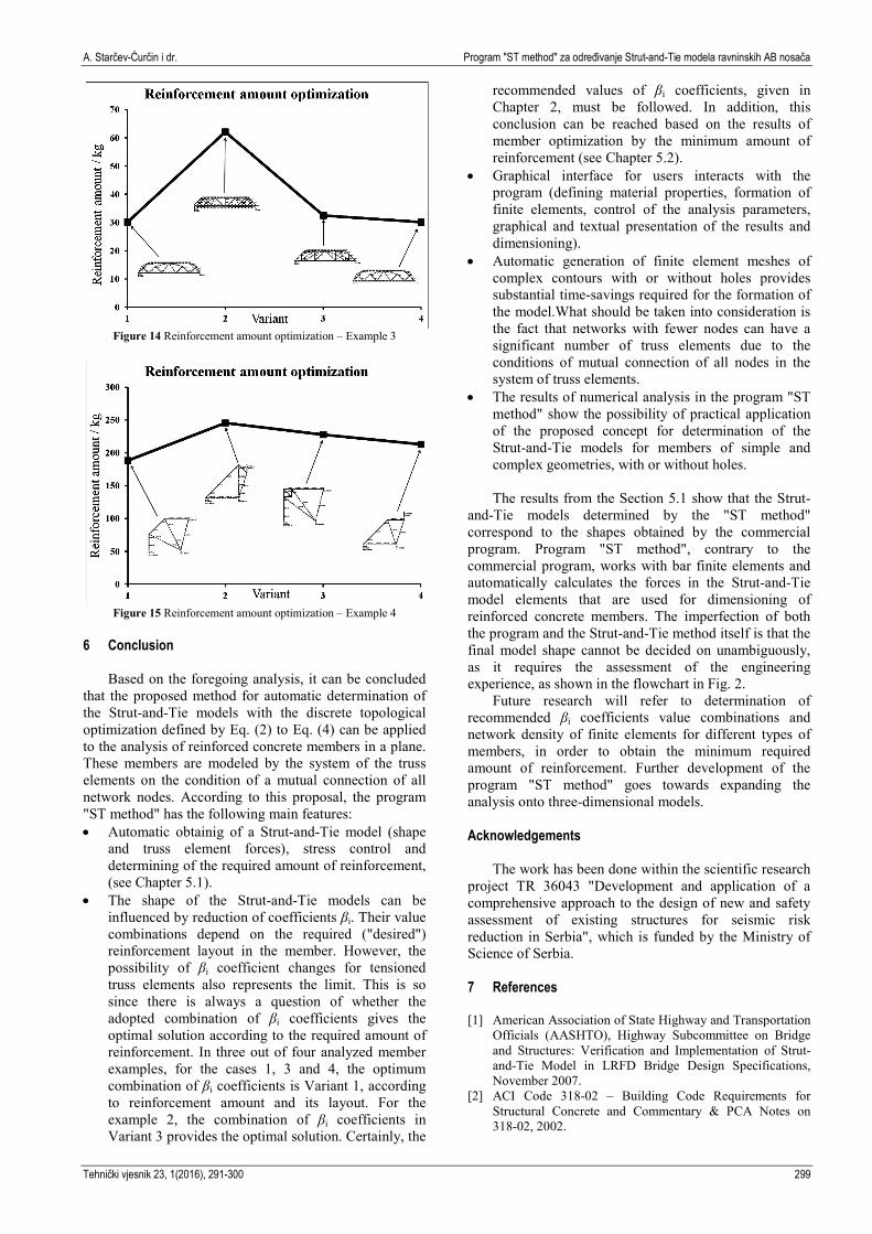
Based on the results presented above, it can be concluded that for the examples 1, 3 and 4, the optimum combination of βi coefficients is Variant 1, according to reinforcement amount and its layout. For the example 2, combination of βi coefficients in Variant 3 provides the optimal solution.
Table 5 Analysed RC members – reinforcement amount optimization – Examples 1, 2, 3 and 4
Member and Parameters for analysis Variant 1 Variant 2 Variant 3 Variant 4
Ec = 30 GPa, Es = 200 GPa Compressed element β = 1
Figure 12 Reinforcement amount optimization – Example 1
Figure 13 Reinforcement amount optimization – Example 2
A. Starčev-Ćurčin i dr. Program "ST method" za određivanje Strut-and-Tie modela ravninskih AB nosača
Tehnički vjesnik 23, 1(2016), 291-300 299
Figure 14 Reinforcement amount optimization – Example 3
Figure 15 Reinforcement amount optimization – Example 4
6 Conclusion
Based on the foregoing analysis, it can be concluded that the proposed method for automatic determination of the Strut-and-Tie models with the discrete topological optimization defined by Eq. (2) to Eq. (4) can be applied to the analysis of reinforced concrete members in a plane. These members are modeled by the system of the truss elements on the condition of a mutual connection of all network nodes. According to this proposal, the program "ST method" has the following main features: • Automatic obtainig of a Strut-and-Tie model (shape
and truss element forces), stress control and determining of the required amount of reinforcement, (see Chapter 5.1).
• The shape of the Strut-and-Tie models can be influenced by reduction of coefficients βi. Their value combinations depend on the required ("desired") reinforcement layout in the member. However, the possibility of βi coefficient changes for tensioned truss elements also represents the limit. This is so since there is always a question of whether the adopted combination of βi coefficients gives the optimal solution according to the required amount of reinforcement. In three out of four analyzed member examples, for the cases 1, 3 and 4, the optimum combination of βi coefficients is Variant 1, according to reinforcement amount and its layout. For the example 2, the combination of βi coefficients in Variant 3 provides the optimal solution. Certainly, the
recommended values of βi coefficients, given in Chapter 2, must be followed. In addition, this conclusion can be reached based on the results of member optimization by the minimum amount of reinforcement (see Chapter 5.2).
• Graphical interface for users interacts with the program (defining material properties, formation of finite elements, control of the analysis parameters, graphical and textual presentation of the results and dimensioning).
• Automatic generation of finite element meshes of complex contours with or without holes provides substantial time-savings required for the formation of the model.What should be taken into consideration is the fact that networks with fewer nodes can have a significant number of truss elements due to the conditions of mutual connection of all nodes in the system of truss elements.
• The results of numerical analysis in the program "ST method" show the possibility of practical application of the proposed concept for determination of the Strut-and-Tie models for members of simple and complex geometries, with or without holes. The results from the Section 5.1 show that the Strut-
and-Tie models determined by the "ST method" correspond to the shapes obtained by the commercial program. Program "ST method", contrary to the commercial program, works with bar finite elements and automatically calculates the forces in the Strut-and-Tie model elements that are used for dimensioning of reinforced concrete members. The imperfection of both the program and the Strut-and-Tie method itself is that the final model shape cannot be decided on unambiguously, as it requires the assessment of the engineering experience, as shown in the flowchart in Fig. 2.
Future research will refer to determination of recommended βi coefficients value combinations and network density of finite elements for different types of members, in order to obtain the minimum required amount of reinforcement. Further development of the program "ST method" goes towards expanding the analysis onto three-dimensional models. Acknowledgements
The work has been done within the scientific research project TR 36043 "Development and application of a comprehensive approach to the design of new and safety assessment of existing structures for seismic risk reduction in Serbia", which is funded by the Ministry of Science of Serbia. 7 References [1] American Association of State Highway and Transportation
Officials (AASHTO), Highway Subcommittee on Bridge and Structures: Verification and Implementation of Strut-and-Tie Model in LRFD Bridge Design Specifications, November 2007.
[2] ACI Code 318-02 – Building Code Requirements for Structural Concrete and Commentary & PCA Notes on 318-02, 2002.
The program "ST method" for determining the Strut-and-Tie models of RC plane members A. Starčev-Ćurčin et al.
300 Technical Gazette 23, 1(2016), 291-300
[3] fib Model Code for Concrete Structures 2010: Published by the Ernst & Sohn, October 2013.
[4] CEB-FIP – (fib): Design examples for strut-and-tie models, Technical Report prepared by Working Party 1.1-3 in fib Task Group 1.1, Design Applications, September 2011.
[5] EN1992-1-1, Design of Concrete Structures, Part 1-1: General rules and rules for buildings, European Committee for Standardization, Brussels, 2004.
[6] Reineck, K. H. Examples for the Design of Structural Concrete with Strut-and-Tie Models, American Concrete Institute, 2002.
[7] Schlaich, J.; Schäfer, K. Design and detailing of structural concrete using strut-and-tie models. // The Structural Engineer. 69, 6(1991), pp. 113-125.
[8] Burns S. A. Recent Advances in Optimal Structural Design, By the Technical Committee on Optimal Structural Design of the Technical Administrative Committee on Analysis and Computation of the Technical Activities Division of the Structural Engineering Institute of the American Society of Civil Engineers, May 3, 2002.
[9] Huang, X.; Xie, Y. M. Evolutionary Topology Optimization of Continuum Structures, Methods and Applications, John Wiley & Sons, United Kingdom, 2010. DOI: 10.1002/9780470689486
[10] Bendsoe, M. P.; Sigmund, O. Topology Optimization, Theory, Methods, and Applications, Springer EUA, New York, 2003.
[11] Bruggi, M. Generating strut-and-tie patterns for reinforced concrete structures using topology optimization. // Computers and Structures. 87, (2009), pp 1483-1495. DOI: 10.1016/j.compstruc.2009.06.003
[12] Hyo-Gyoung, Kwak; Sang-Hoon, Noh. Determination of strut-and-tie models using evolutionary structural optimization. // Engineering Structures - ENG STRUCT 08/2006. 28, 10(2006), pp. 1440-1449. DOI: 10.1016/j.engstruct.2006.01.013
[13] Kostić, N. Computer-based development of stress fields. // 6th International PhD Symposium in Civil Engineering, Zurich, August 23-26, 2006.
[14] Kostić, N. Topologie des champs de contraintes pour le dimensionnement des structures en beton arme. // These No 4414 (2009), Ecole Polytechnique federale de Lausanne, Suisse, 11 Juin 2009.
[15] Fernandez Ruiz, M.; Muttoni, A. On Development of Suitable Stress Fields for Structural Concrete. // ACI Structural Journal. 104, 4(2007), pp. 495-502.
[16] Starčev Ćurčin, A.; Rašeta, A.; Brujić, Z. Automatic Generation of Planar Strut-And-Tie Models. // Facta Universitatis, Series: Architecture and Civil Engineering. 11, 1(2013), pp. 1-12, DOI: 10.2298/FUACE1301001S
Authors’ addresses Anka Starčev-Ćurčin, MSc, BSc, Civ. Eng., Teaching Assistant University of Novi Sad, Faculty of Technical Sciences, Trg Dositeja Obradovića 6, 21000 Novi Sad, Republic of Serbia Tel. +381 63 77 21 699, E-mail: [email protected] Andrija Rašeta, PhD, MSc, BSc, Civ. Eng., Teaching Assistant University of Novi Sad, Faculty of Technical Sciences, Trg Dositeja Obradovića 6, 21000 Novi Sad, Republic of Serbia Tel. +381 65 21 21 255, E-mail: [email protected] Zoran Brujić, PhD, MSc, BSc, Civ. Eng., Professor University of Novi Sad, Faculty of Technical Sciences, Trg Dositeja Obradovića 6, 21000 Novi Sad, Republic of Serbia Tel. +381 21 485 2613, E-mail: [email protected]


![ISSN 1330-3651 (Print), ISSN 1848-6339 (Online) DOI: … · are specified in ISO 5817 [4] and ISO 10042 [5]. According to the American Society of Mechanical Engineers, welding defect](https://static.documents.pub/doc/80x56/612e81e21ecc51586942db76/issn-1330-3651-print-issn-1848-6339-online-doi-are-specified-in-iso-5817-4.jpg)


![L. Barna i dr. ISSN 1330 -3651 (Print), ISSN 1848-6339 ... · added hydrogen can reducethe total fuel experimentallyconsumption even under heavy load. Song [6] concluded that, if](https://static.documents.pub/doc/80x56/5e32545e28d1aa5cdf5a8514/l-barna-i-dr-issn-1330-3651-print-issn-1848-6339-added-hydrogen-can-reducethe.jpg)


